EP3949900B1 - Winkeleinstellplattformvorrichtung für dentaltechnik - Google Patents
Winkeleinstellplattformvorrichtung für dentaltechnik Download PDFInfo
- Publication number
- EP3949900B1 EP3949900B1 EP19922202.7A EP19922202A EP3949900B1 EP 3949900 B1 EP3949900 B1 EP 3949900B1 EP 19922202 A EP19922202 A EP 19922202A EP 3949900 B1 EP3949900 B1 EP 3949900B1
- Authority
- EP
- European Patent Office
- Prior art keywords
- sphere
- fan
- substrate
- diameter
- shaped plate
- Prior art date
- Legal status (The legal status is an assumption and is not a legal conclusion. Google has not performed a legal analysis and makes no representation as to the accuracy of the status listed.)
- Active
Links
Images




Classifications
-
- A—HUMAN NECESSITIES
- A61—MEDICAL OR VETERINARY SCIENCE; HYGIENE
- A61C—DENTISTRY; APPARATUS OR METHODS FOR ORAL OR DENTAL HYGIENE
- A61C13/00—Dental prostheses; Making same
- A61C13/10—Fastening of artificial teeth to denture palates or the like
- A61C13/1003—Fastening of artificial teeth to denture palates or the like by embedding in base material
- A61C13/1013—Arch forms
- A61C13/1016—Methods or apparatus for mounting, holding or positioning a set of teeth
-
- A—HUMAN NECESSITIES
- A61—MEDICAL OR VETERINARY SCIENCE; HYGIENE
- A61C—DENTISTRY; APPARATUS OR METHODS FOR ORAL OR DENTAL HYGIENE
- A61C19/00—Dental auxiliary appliances
- A61C19/04—Measuring instruments specially adapted for dentistry
-
- A—HUMAN NECESSITIES
- A61—MEDICAL OR VETERINARY SCIENCE; HYGIENE
- A61C—DENTISTRY; APPARATUS OR METHODS FOR ORAL OR DENTAL HYGIENE
- A61C13/00—Dental prostheses; Making same
- A61C13/01—Palates or other bases or supports for the artificial teeth; Making same
-
- A—HUMAN NECESSITIES
- A61—MEDICAL OR VETERINARY SCIENCE; HYGIENE
- A61C—DENTISTRY; APPARATUS OR METHODS FOR ORAL OR DENTAL HYGIENE
- A61C13/00—Dental prostheses; Making same
- A61C13/12—Tools for fastening artificial teeth; Holders, clamps, or stands for artificial teeth
-
- A—HUMAN NECESSITIES
- A61—MEDICAL OR VETERINARY SCIENCE; HYGIENE
- A61C—DENTISTRY; APPARATUS OR METHODS FOR ORAL OR DENTAL HYGIENE
- A61C19/00—Dental auxiliary appliances
- A61C19/04—Measuring instruments specially adapted for dentistry
- A61C19/055—Paralleling devices
Definitions
- the present invention relates to an angle adjustment stage device for dental technique, particular to, an angle adjustment stage device used in design of a hook and a base of a removable partial denture for replacement of missing teeth.
- Fig. 8 is a perspective view of an example of a removable partial denture mounted on a plaster model.
- the removable partial dentures 33 comprise artificial teeth 34 and clasps 36 engaged with clasped teeth 35 adjacent to the removable partial dentures 33.
- a plaster model 37 is made by modeling target teeth and mucous membranes from a patient's mouth cavity, and the clasped teeth 35 for the removable partial dentures 33 are chosen from residual teeth of the plaster model 37, and then the clasps 36 are designed and produced in such a way that they fit the curved surfaces of the clasped teeth 35.
- clasps 36 There are two types of clasps 36, that is, a wire clasp which is made by bending a metal wire and a cast clasp which is made by casting alloys.
- the clasp 36 is composed of a clasp tang 38 embedded into the removable partial denture 33 so as to be integrated with the removable partial denture 33, a clasp body 39 connected to the clasp tang 38 and engaging with an adjacent surface of the clasped tooth 35, and a clasp arm 40 connected to the clasp body 39 and surrounding the clasped tooth 35 at an undercut area of the clasped teeth 35 (an area underside of a circumferential line (surveyor line) of the tooth).
- the clasp arm 40 is composed of an upper arm portion 40a, a middle arm portion 40b and clasp tip 40c in order closest to the clasp body 39.
- the clasp arm 40 which extends from the removable partial denture 33 in such a manner that it surrounds the clasped tooth 35, engages with the undercut area of the clasped tooth 35 so as to prevent the removable partial denture 33 from disengaging and wobbling.
- the setting of the degree of bending of the clasp arm 40 is very important for design and production of the clasp 36, and therefore, one of the important design items of the removable partial denture 33 because the amount of the clasp arm's bending into the undercut area has a huge effect on comfort and load on the clasped tooth 35 when wearing the removable partial denture 33, and aesthetics of the removable partial denture 33.
- the inventor of the present invention has proposed "IBA Denture Design Method” as a wire clasp design method.
- a plaster model M is set on an initial setting position (see Fig. 9(A) .
- a straight line D1 indicates a vertical direction
- a baseline (circumferential line) L1 is drawn on the plaster model M, and each time the plaster model M is rotated to buccal and lingual sides by a predetermined angle (usually 15 degrees), an inclined line (outline of clasp) L2 is drawn on a side of the clasped tooth 35 (see Fig. 9(B) .
- a straight line D2 indicates a vertical direction).
- the wire clasp is designed in a manner such that a whole of the clasp arm (the clasp tip, the middle arm portion and the upper arm portion) is located in the undercut area.
- an angle adjustment stage device comprising a first rotary member attached to a support post on a base so as to be rotatable around a horizontal axis, and a second rotary member arranged in an interior space of the first rotary member so as to be rotatable around an axis perpendicular to the horizontal axis, the first rotary member being fixed to the support post at a desired rotational position, the second rotary member being fixed to the first rotary member at a desired rotational position.
- the angle adjustment stage device further comprises a universal joint mechanism attached to the second rotary member in a manner such that a rotational center of the universal joint mechanism is located on a vertical axis, a support rod connected to the second rotary member through the universal joint mechanism at lower end thereof, a stage connected to an upper end of the support rod, a means (third fixing means) for fixing the support rod at a desired tilt position, and a means (fourth fixing means) for fixing the support rod after rotating the support rod from the desired tilt position around an axis which is chosen from the horizontal axis and axes parallel to the horizontal axis and passes through the rotational center of the universal joint by a desired angle (see Patent Document 1).
- this angle adjustment stage device the number of both a rotary part and a part for fixing the rotational position is reduced so that the simplification of device, the reduction of manufacturing costs and the improved operability of the device can be achieved to some extent.
- this angle adjustment stage device is still expensive and is not easy to maintain. In addition, it takes a long time to get familiar with the operation of the device.
- Patent Document 1 JP 6150093 B
- the present invention provides an angle adjustment stage device for dental technique comprising: a base; a stage arranged above the base, a workpiece for dental technique being fixed on the stage; and a stage support mechanism provided on the base to support the stage in a manner such that a tilt angle of the stage is adjustable.
- the stage support mechanism includes a base shaft arranged in protruding manner on the base and having a magnet therein, and a rocking body magnetically coupled to the tip of the base shaft.
- the rocking body includes a square substrate, a sphere formed from ferromagnet, a sphere holder arranged at the center of the substrate so as to be rotatable around an axis which extends through the center of the substrate and perpendicular to the substrate, and a first stopper for fixing the sphere holder to the substrate at a desired rotational position, the sphere holder holding the sphere in a manner such that the sphere can be rotated around the center thereof and fixed at a desired rotational position while the center of the sphere is on the axis extending perpendicular to the substrate.
- the rocking body further includes a support rod extending radially outward form the sphere and connected to a lower surface of the stage at an upper end thereof, a lower portion of the sphere protruding from the underside of each of the sphere holder and the substrate, the rocking body being magnetically coupled to a receiving portion of the tip of the base shaft at a lower end of the sphere.
- the stage support mechanism further includes an elevating body fitted on the base shaft so as to vertically slide along the base shaft, and a second stopper attached to the elevating body and/or the base shaft for fixing the elevating body to the base shaft at a desired height.
- An upper surface of the elevating body forms a horizontal plane and has a recess for receiving the lower portion of the sphere, and a through hole is formed on a bottom surface of the recess to reach a lower surface of the elevating body, and the through hole has a diameter corresponding to a diameter of the base shaft so that the base shaft is inserted through the through hole.
- the rocking body takes a horizontal position when the elevating body is located at the highest point to contact a lower surface of the substrate of the rocking body at an upper surface thereof, while the rocking body takes a tilt position when one of four sides of the substrate is brought into contact with the upper surface of the elevating body after the elevating body is lowered from the highest point while separating the upper surface thereof from the lower surface of the substrate.
- the angle adjustment stage device for dental technique further comprises an angle display mechanism displaying a tilt angle at the tilt position of the rocking body depending on the height of the elevating body.
- a first circular recess is formed at the center of the lower surface of the substrate of the rocking body, and a first circular opening whose diameter is larger than a diameter of the sphere is formed at the center of a bottom surface of the first circular recess to reach an upper surface of the substrate.
- the sphere holder of the rocking body comprises a holder body having a large diameter portion whose diameter is larger than the diameter of the first circular opening, and a small diameter portion connecting coaxially to a lower end surface of large diameter portion and having a thickness which corresponds to a depth of the first circular opening and a diameter which corresponds to the diameter of the first circular opening.
- a second circular recess whose diameter is larger than the diameter of the sphere is formed at the center of an upper end surface of the large diameter portion, and a second circular opening is formed at the center of a bottom surface of t he second circular recess to reach a lower end surface of the small diameter portion and having a diameter which is smaller than the diameter of the sphere.
- the sphere holder further comprises an annular member having a thickness which is smaller than a depth of the first circular recess, an outer diameter which is larger than the diameter of the first circular opening, but smaller than the diameter of the first circular recess and an inner diameter which corresponds to the diameter of the second circular opening.
- the annular member is combined coaxially with the lower end surface of the small diameter portion while the small diameter portion is fitted into the first circular opening of the substrate, and the holder body is attached to the substrate so as to be rotatable around the axis extending perpendicular to the substrate.
- the sphere holder further comprises an annular sphere holding member having an outer diameter which equals to the diameter of the first circular opening and an inner diameter which is smaller than the diameter of the sphere.
- First screw holes are formed at more than three positions which are spaced from each other in a circumferential direction of the sphere holding member so as to penetrate both end surfaces of the sphere holding member, while second screw holes are formed at positions corresponding to the first screw holes on a bottom surface of the second circular recess of the holder body.
- the sphere holding member further comprises fixing screws being screwed into the first and second screw holes, the fixing screws being screwed into the first and second screw holes from the outside of the sphere holding member with the sphere nipped between the bottom surface of the second circular recess of the holder body and the sphere holding member.
- a plurality of recesses are formed on an outer peripheral surface of the small diameter portion of the holder body at equal distances, and at least one radial hole is formed at positions which correspond to the plurality of recesses on an inner wall of the first circular opening of the substrate and extends radially outward from the axis extending perpendicular to the substrate, and the first stopper consists of at least one ball plunger arranged in the at least one radial hole and elastically urged toward the outer peripheral surface of the small diameter portion to engage with the plurality of recesses of the small diameter portion.
- the base shaft is rotatable around an axis thereof and has a flange at a lower portion thereof.
- the angle display mechanism includes a pair of fan-shaped plates are connected to each other so as to be rotatable around the center of each other.
- the tip of a radial side edge of a first fan-shaped plate of the pair of fan-shaped plates or an extension extending outward from the first fan-shaped plate along the radial side edge is attached to the flange of the base shaft so as to be rotatable around a horizontal axis.
- the tip of a radial side edge of a second fan-shaped plate of the pair of fan-shaped plates closer to the radial side edge of the first fun-shaped plate or an extension extending outward from the second fan-shaped plate along the radial side edge of the second fan-shaped plate is attached to a side wall of the elevating body so as to be rotatable around an axis parallel to the horizontal axis, so that the pair of fan-shaped plates rotate around the center of each other in a vertical plane as the elevating body moves up and down.
- An angle scale which corresponds to the tilt angle of the rocking body is attached on a peripheral wall of the first fan-shaped plate, and a zero point scale is attached on a peripheral wall of the second fan-shaped plate.
- the base shaft is fixed to the base
- the angle display mechanism includes a pair of fan-shaped plates connected to each other so as to be rotatable around the center of each other.
- the tip of a radial side edge of a first fan-shaped plate of the pair of fan-shaped plates or an extension extending outward from the first fan-shaped plate along the radial side edge is attached to the base so as to be rotatable around a horizontal axis.
- the tip of a radial side edge of a second fan-shaped plate of the pair of fan-shaped plates closer to the radial side edge of the first fun-shaped plate or an extension extending outward from the second fan-shaped plate along the radial side edge of the second fan-shaped plate is attached to a side wall of the elevating body so as to be rotatable around an axis parallel to the horizontal axis, so that the pair of fan-shaped plates rotate around the center of each other in a vertical plane as the elevating body moves up and down.
- An angle scale which corresponds to the tilt angle of the rocking body is attached on a peripheral wall of the first fan-shaped plate, and a zero point scale is attached on a peripheral wall of the second fan-shaped plate.
- the angle adjustment stage device for dental technique further comprises a marking unit attached to the base so as to draw a line for design on the workpiece for dental technique fixed on the stage.
- the marking unit includes a pole projected vertically on the base, an arm attached to the pole and extending radially from the pole and arranged on a plane perpendicular to the pole so as to be rotatable around an axis of the pole, a pen holder attached to the tip of the arm, and a pen held by the pen holder and extending downward from the pen holder and parallel to the pole.
- the present invention compared with the conventional angle adjustment stage device, the number of parts which make up the angle adjustment stage device is reduced, and the device configuration becomes easier, thereby device manufacturing costs are significantly reduced and the device can be miniaturized and the maintenance of the device also becomes easier.
- the number of parts to be operated for adjusting the angle of the stage is reduced and it is easy to operate those parts, and therefore, even beginners can master the operation of the device in a short period of time.
- Fig. 1 is a perspective view of an angle adjustment stage device for dental technique according to an embodiment of the present invention
- Fig. 2 is a longitudinal section a stage support mechanism of the angle adjustment stage device for dental technique shown in Fig. 1
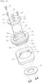
- Fig. 3 is a disassembled perspective view of a rocking body of the angle adjustment stage device for dental technique shown in Fig. 1
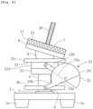
- Fig. 4 is a side view of the angle adjustment stage device for dental technique shown in Fig. 1 .
- an angle adjustment stage device of the present invention comprises a base 1, a stage 2 arranged above the base 1, a workpiece W for dental technique being fixed on the stage 2, and a stage support mechanism 3 provided on the base 1 to support the stage 2 in a manner such that a tilt angle of the stage 2 is adjustable,
- the base 1 has a rectangular plate shape, and rubber legs 1a are attached to four corners of the underside of the base 1.
- the stage support mechanism 3 includes a base shaft 4 arranged in protruding manner on the base through a thrust bearing 5 to be rotatable around an axis of the base shaft 4.
- the base shaft 4 has a magnet 6 therein, and an upper end surface of the magnet 6 is exposed on a bottom surface of a receiving portion 4a which is formed at the tip of the base shaft 4 so as to receive a sphere 9 (described later).
- the base shaft also has a flange 4b at a lower portion thereof.
- the stage support mechanism 3 further includes a rocking body 7 magnetically coupled to the tip of the base shaft 4 (receiving portion 4a).
- the rocking body 7 includes a square substrate 8, a sphere 9 formed from ferromagnet, and a sphere holder 10 arranged at the center of the substrate 8 so as to be rotatable around an axis Z which extends through the center of the substrate 8 and perpendicular to the substrate 8.
- a first circular recess 8b is formed at the center of a lower surface of the substrate 8 and a first circular opening 8a whose diameter is larger than a diameter of the sphere 9 is formed at the center of a bottom surface of the first circular recess to reach an upper surface of the substrate 8.
- the sphere holder 10 comprises an holder body 13 having a large diameter portion 11 whose diameter is larger than the diameter of the first circular opening 8a, and a small diameter portion 12 connecting coaxially to a lower end surface of large diameter portion 11 and having a thickness which corresponds to a depth of the first circular opening 8a and a diameter which corresponds to the diameter of the first circular opening 8a.
- a second circular recess 11a whose diameter is larger than the diameter of the sphere 9 is formed at the center of an upper end surface of the large diameter portion 11, and a second circular opening 12a is formed at the center of a bottom surface of the second circular recess 11a to reach a lower end surface of the small diameter portion 12 and having a diameter which is smaller than the diameter of the sphere 9.
- the sphere holder 10 further comprises an annular member 14 having a thickness which is smaller than a depth of the first circular recess 8b, an outer diameter which is larger than the diameter of the first circular opening 8a, but smaller than the diameter of the first circular recess 8b and an inner diameter which corresponds to the diameter of the second circular opening 12a.
- the annular member 14 is concentrically attached to the lower end surface of the small diameter portion 12 through screws, while the small diameter portion 12 of the holder body 13 is fitted into the first circular opening 8a of the substrate 12, and thereby the holder body 13 is attached to the substrate 8 so as to be rotatable around the axis Z.
- a plurality of recesses (in this embodiment, four recesses) 12b are formed on an outer peripheral surface of the small diameter portion 12 at equal distances, and radial holes (not shown) are formed at positions corresponding to the plurality of recesses on an inner wall of the first circular opening 8a of the substrate 8 and extend radially outward from the axis Z of the substrate 8.
- a ball plunger 15 is arranged in each of the radial holes and always elastically urged toward the outer peripheral surface of the small diameter portion 12.
- the ball plungers 15 constitute a first stopper for fixing the sphere holder 10 to the substrate 8 of the rocking body 7 at a desired rotational position.
- a configuration of the first stopper is not limited to this embodiment.
- the reference position of the workpiece W fixed on the stage 2 is defined by one rotational position at which the ball plungers 15 engage with the recesses 12b (this will be described later).
- the sphere holder 10 also comprises an annular sphere holding member 16 having an outer diameter which equals to the diameter of the first circular opening 8a and an inner diameter which is smaller than the diameter of the sphere 9.
- First screw holes 17 are formed at more than three positions which are spaced from each other in a circumferential direction of the sphere holding member 16 so as to penetrate both end surfaces of the sphere holding member 16, while second screw holes 18 are formed at positions corresponding to the first screw holes 17 on a bottom surface of the second circular recess 11a of the holder body 13.
- the sphere holder 10 further comprises fixing screws 19 being screwed into the first and second screw holes 17, 18.
- the fixing screws 19 are screwed into the first and second screw holes 17, 18 from the outside of the sphere holding member 16 while the sphere 9 whose center is on the axis Z extending perpendicular to the substrate 8 is nipped between the bottom surface of the second circular recess 11a of the holder body 13 and the sphere holding member 16 with a lower portion of the sphere 9 protruding from the underside of each of the sphere holder 10 and the substrate 8.
- the sphere 9 becomes rotatable while being magnetically coupled to the receiving portion 4b by loosening the fixing screws 19, and the sphere 9 is fixed between the bottom surface of the second circular recess 11a of the holder body 13 and the sphere holding member 16 by tightening the fixing screws 19.
- the rocking body 7 further includes a support rod 20 extending radially outward form the sphere 9.
- a lower surface of the stage 2 is connected to an upper end of the support rod 20.
- the rocking body 7 is magnetically coupled to the receiving portion 4a (magnet 6) of the tip of the base shaft 4 at a lower end of the sphere 9.
- the magnet 6 has a magnetic force which causes a magnetic coupling force large enough to maintain positional relationship of the sphere 9 with respect to the receiving portion 4a.
- the stage support mechanism 3 also includes an elevating body 21 fitted on the base shaft 4 so as to vertically slide along the base shaft 4.
- the elevating body 21 is composed of a rectangular (or square) flat upper portion 21c and a columnar lower portion 21d concentrically connecting to the center of the underside of the upper portion 21c.
- An upper surface of the upper portion 21c forms a horizontal plane, and an recess 21a for receiving the lower portion (portion protruding from the underside of each of the substrate 8 and the sphere holder 10) of the sphere 9 opens on the upper surface of the upper portion 21c, and a through hole 21b is formed on a bottom surface of the recess 21a to reach the underside of elevating body 21.
- the through hole 21b has a diameter corresponding to a diameter of the base shaft 4.
- a set collar 22 whose inner diameter corresponds to the through hole 21b is attached to the underside of the elevating body 21, and the base shaft 4 is inserted through the through hole 21b and the set collar 22.
- the elevating body 21 becomes slidably along the base shaft 4 by loosening a clamp screw 22a, and the elevating body 21 is fixed to the base shaft 4 at a desired height by tightening the clamp screw 22a.
- the set collar 22 constitutes a second stopper for fixing the elevating body 21 to the base shaft 4 at a desired height.
- a configuration of the second stopper is not limited to this embodiment.
- the rocking body 7 takes a horizontal position when the elevating body 21 is located at the highest point to contact the lower surface of the substrate 8 of the rocking body 7 at an upper surface thereof (see Fig. 2 ), while the rocking body 7 takes a tilt position when one of four sides of the substrate 8 is brought into contact with the upper surface of the elevating body 21 after the elevating body 21 is lowered from the highest point while separating the upper surface thereof from the lower surface of the substrate 8 (see Fig. 4 ).
- the axis Z coincides with a vertical axis (axis perpendicular to the upper surface of the elevating body 21) (see Fig. 2 ), wherein the stage 2 (support rod 20)can be tilted through the sphere 9 by loosening fixing screws 19, while the stage 2 (support rod 20) can be fixed at a desired tilt position by tightening the fixing screws 19.
- the stage 2 (support rod 20) can be rotated by the tilt angle of the rocking body 7 clockwise or counterclockwise around one of horizontal two axes (X-Y axes) which extend through the center of the sphere 9 and are orthogonal to each other on a vertical axis.
- X-Y axes horizontal two axes
- the angle adjustment stage device for dental technique of the present invention further comprises an angle display mechanism 23 displaying the tilt angle at the tilt position of the rocking body 7 depending on the height of the elevating body 21.
- the angle display mechanism 23 includes a pair of fan-shaped plates 24, 25 connected to each other so as to be rotatable around the center of each other.
- a first fan-shaped plate 24 of the pair of fan-shaped plates 24, 25 has an extension 24b extending outward from the first fan-shaped plate 24 along a radial side edge 24a of the first fan-shaped plate 24, while a second fan-shaped plate 25 of the pair of fan-shaped plates 24, 25 has an extension 25b extending outward from the second fan-shaped plate 25 along a radial side edge 25a closer to the radial side edge 24a of the first fan-shaped plate 24.
- the tip of the extension 24b of the first fan-shaped plate 24 is attached to a mounting shaft 26 extending horizontally in a radial direction from a peripheral wall of the flange 4b of the base shaft 4 so as to be rotatable around an axis of the mounting shaft 26, while the tip of the extension 25b of the second fan-shaped plate 25 is attached to a mounting shaft 27 extending radially from a side wall of the lower portion 21d of the elevating body 21 and parallel with the mounting shaft 26 so as to be rotatable around an axis of the mounting shaft 27.
- an angle scale S1 which corresponds to the tilt angle of the rocking body 7 is attached on a peripheral wall of the first fan-shaped plate 24, and a zero point scale S2 is attached on a peripheral wall of the second fan-shaped plate 25.
- the angle scale S1 is pre-created as follows.
- the elevating body 21 is fixed at the highest point thereof (the rocking body 7 takes the horizontal position), and a zero scale is assigned to a point of the angle scale S1 which corresponds to the zero point scale S2.
- the tilt angle of the tilt position of the rocking body is measured and the measured value is assigned to a point of the angle scale S1 which corresponds to the zero point scale S2 each time the height of the elevating body 21 is changed.
- the elevating body 21 is fixed at a height at which the angle indicated by the zero point scale S2 becomes a desired angle, and then one of four sides of the substrate 8 of the rocking body 7 is brought into contact with the upper surface of the elevating body 21.
- the stage 2 (support rod 20) is rotated by the desired angle clockwise or counterclockwise around one of the horizontal two axes (X-Y axes) which extend through the center of the sphere 9 and are orthogonal to each other on the vertical axis.
- the pair of fan-shaped plates 24, 25 is the extension 24b, 25b in this embodiment
- the pair of fan-shaped plates 24, 2After5 may be attached directly to the associated mounting shafts 26, 27 at the tips of radial side edges 24a, 25a thereof so as to be rotatable around the axes of the mounting shafts 26, 27 without the extensions 24b, 25b.
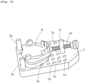
- Fig. 5 is a perspective view of the stage 2 with the workpiece for dental technique W fixed thereon.
- the stage 2 is formed in a flat plate shape and has holes 2a evenly spaced in longitudinal and width directions of the stage 2.
- a pair of receiving pins 2b, 2b and a tightening pin 2c provided with a clamping screw 2d are selectively fitted into any of these holes 2a.
- the workpiece W is fixed on the stage 2 by clamping the workpiece W between the pair of receiving pins 2b, 2b and the clamping screw 2d.
- a marking unit 28 is provided to draw a line for design on the workpiece for dental technique W fixed on the stage 2.
- the marking unit 28 includes a pole 29 projected vertically on the base 1, an arm 30 attached to the pole 29 and extending radially from the pole 29 and arranged on a plane perpendicular to the pole 29 so as to be rotatable around an axis of the pole 29, a pen holder 31 attached to the tip of the arm 30, and a pen 32 held by the pen holder 31 and extending downward from the pen holder 31 and parallel to the pole 29.
- the marking unit 28 is provided to draw the surveyor line on the plaster model because the angle adjustment stage device is intended to use for design of the clasp and removable partial denture and therefore the plaster model is assumed as a workpiece for dental technique W, but the workpiece for dental technique W is not limited to the plaster model.
- a suitable cutting or polishing unit is provided instead of the marking unit 28.
- the angle adjustment stage device of the present invention may be used to locate an attachment and produce an implant stent and so on.
- the plaster model as the workpiece for dental technique W is fixed on the stage 2.
- the ball plungers 15 of the substrate 8 of the rocking body 7 engage with the recesses 12b of the sphere holder 10 so that the plaster model W is located at a reference position (shown in Fig. 9(C) ).
- the elevating body 21 is fixed at a height (highest point) where the zero point scale S2 of the angle display mechanism 23 coincides with the zero point of the angle scale S1.
- a baseline (circumferential line) is drawn on the plaster model W by the marking unit 28 (pen 32) while rotating the stage 2, the rocking body 7, the elevating body 21 and the base shaft 4 together around the vertical axis (L1 in Fig. 9(A) ).
- the clamp screw 22a of the set collar 22 is loosen, and the elevating body 21 is lowered until the zero point scale S2 of the angle display mechanism 23 coincides with 15 degrees on the angle scale S1, and then the elevating body 21 is fixed at the height by tightening the clamp screw 22a again.
- the stage 2 is located at the tilt position so as to be tilted to the left and right of the plaster model W (the stage 2 is rotated clockwise and counterclockwise around the X axis shown in Fig. 9(C) ), and in each case, an inclined line (outline of clasp) is drawn on buccal ang lingual sides of the clasped tooth 35 of the plaster model W by the pen 32, while rotating the stage 2, the rocking body 7, the elevating body and the base shaft together around the vertical axis (L2 in Fig. 9(A) ).
- the buccal and lingual sides balance between the baseline L1 and the outline of clasp L2 is checked by contrasting those lines. The work is completed when the balance is good, but, when the balance is not good, it is necessary to change (adjust) the initial setting position of the stage 2 and draw a new outline of clasp again.
- a method of change (adjustment) of the initial setting position is as follows.
- the elevating body 21 is lowered to a desired angle while looking at the angle display mechanism 23, and the elevating body 21 is fixed at the desired angle by tightening the clamp screw 22a.
- the free rocking body 7 is adjusted to the desired tilt angle with respect to the X axis or the Y axis by bringing the associated one side of the substrate 8 of the rocking body 7 into contact with the upper surface of the elevating body 21, and the sphere 9 is fixed to the rocking body 7 by the fixing screws 19.
- the clamp screw 22a of the set collar 22 is loosen and the elevating body 21 is raised until the zero point scale S2 of the angle display mechanism 23 coincides with the zero point of the angle scale S1, so that the change (adjustment) of the initial setting position of the stage 2 is completed.
- the sphere holder 10 is rotated until the alpha ( ⁇ ) axis coincides with the X axis or the Y axis while setting the stage 2 in the initial setting position. After that, the change (adjustment) is completed by operating in the same way as the case (1).
- the present invention compared with the conventional angle adjustment stage device, the number of parts which make up the angle adjustment stage device is reduced, and the device configuration becomes easier, thereby device manufacturing costs are significantly reduced and the device can be miniaturized and the maintenance of the device also becomes easier.
- the number of parts to be operated for adjusting the angle of the stage 2 is reduced and it is easy to operate those parts and therefore, even beginners can master the operation of the device in a short period of time.
- Fig. 6 is a longitudinal section of a stage support mechanism of an angle adjustment stage device for dental technique of another embodiment of the present invention
- Fig. 7 is a side view of the angle adjustment stage device for dental technique shown in Fig. 6 .
- FIGs. 6 and 7 differs from the embodiment shown in Figs. 1 through 5 only in a mounting structure of the base shaft to the base and a mounting position of the angle display mechanism. Therefore, in Figs. 6 and 7 , the same elements as shown in Figs. 1 through 5 are identified with the same reference numerals as used in Figs. 1 through 5 , and the detailed explanation thereof will be omitted in what follows.
- a base shaft 4' is fixed to the base 1 so as not to be rotatable around an axis thereof and has no flange.
- the base shaft 4' has the magnet 6 therein, and an upper end surface of the magnet 6 is exposed on a bottom surface of a receiving portion 4a' which is formed at the tip of the base shaft 4' so as to receive the sphere 9.
- the tip of the extension 25b of the second fan-shaped plate 25 of the angle display mechanism 23 is attached to the mounting shaft 27 of the elevating body 21 so as to be rotatable around the axis of the mounting shaft 27, while the tip of the extension 24b of the first fan-shaped plate 24 is attached to a mounting shaft 26', which is attached to the side of the base 1 and extends parallel to the mounting shaft 27, so as to be rotatable around an axis of the mounting shaft 26'.
- the pair of fan-shaped plates 24, 25 rotate around the center (connection point) of each other in a vertical plane as the elevating body 21 moves up and down.
- the rotation of the stage 2 around the vertical axis in the initial setting position is performed by rotating the stage 2 and the rocking body 7 together around an axis Z while bringing the lower surface of the substrate 8 of the rocking body 7 into contact with the upper surface of the elevating body 21.
- the rotation of the stage 2 around the vertical axis in the tilt position is performed by rotating the stage 2 and the rocking body 7 together around the receiving portion 4a' of the base shaft 4' as a pivot point while bringing the associated side of the substrate 8 into contact with the upper surface of the elevating body 21.
- the sphere holder 10 may have any configuration as far as the sphere holder 10 is arranged at the center of the substrate 8 so as to be rotatable around the axis Z which extends through the center of the substrate 8 and perpendicular to the substrate 8.
- the angle display mechanism 23 may have any configuration as far as the angle display mechanism 23 displays a tilt angle at the tilt position of the rocking body depending on the height of the elevating body.
Landscapes
- Health & Medical Sciences (AREA)
- Oral & Maxillofacial Surgery (AREA)
- Life Sciences & Earth Sciences (AREA)
- General Health & Medical Sciences (AREA)
- Epidemiology (AREA)
- Animal Behavior & Ethology (AREA)
- Dentistry (AREA)
- Public Health (AREA)
- Veterinary Medicine (AREA)
- Engineering & Computer Science (AREA)
- Biomedical Technology (AREA)
- Biophysics (AREA)
- Dental Tools And Instruments Or Auxiliary Dental Instruments (AREA)
Claims (6)
- Winkeleinstellplattformvorrichtung für die Zahntechnik, umfassend:eine Basis (1);eine Plattform (2), die oberhalb der Basis angeordnet ist, ein Zahntechnik-Werkstück (W), das angepasst ist, um auf der Plattform befestigt zu werden; undeinen Plattformträgermechanismus (3), der auf der Basis bereitgestellt wird, um die Plattform so zu tragen, dass ein Neigungswinkel der Plattform einstellbar ist,wobei der Plattformträgermechanismus umfasst:einen Basisschaft (4), der hervorstehend auf der Basis angeordnet ist und einen Magneten (6) darin enthält, undeinen Kippkörper (7), der magnetisch mit der Spitze des Basisschafts verbunden ist,wobei der Kippkörper umfasst:eine quadratische Trägerplatte (8),eine aus einem Ferromagneten gebildete Kugel (9),einen Kugelhalter (10), der in der Mitte der Trägerplatte angeordnet ist, um sich um eine Achse, die durch die Mitte der Trägerplatte und senkrecht zur Trägerplatte verläuft, drehen zu können, undeinen ersten Stopper (15) zum Fixieren des Kugelhalters an der Trägerplatte in einer erwünschten Drehposition,wobei der Kugelhalter die Kugel so hält, dass die Kugel um ihren Mittelpunkt gedreht und in einer erwünschten Drehposition fixiert werden kann, während der Mittelpunkt der Kugel sich auf der Achse befindet, die senkrecht zur Trägerplatte verläuft,wobei der Kippkörper ferner umfasst:einen Stützstab (20), der sich von der Kugel radial nach außen erstreckt und an einem oberen Ende davon mit einer Unterseite der Plattform verbunden ist,wobei ein unterer Teil der Kugel von der Unterseite sowohl des Kugelhalters als auch der Trägerplatte hervorsteht, wobei der Kippkörper magnetisch mit einem Aufnahmeteil der Spitze des Basisschafts an einem unteren Ende der Kugel verbunden ist,wobei der Plattformträgermechanismus ferner umfasst:einen Hebekörper (21), der so am Basisschaft montiert ist, dass er vertikal entlang des Basisschafts gleitet, undeinen zweiten Stopper (22), der am Hebekörper und/oder dem Basisschaft angebracht ist, um den Hebekörper in einer erwünschten Höhe am Basisschaft zu fixieren,wobei eine Oberseite des Hebekörpers eine horizontale Ebene bildet und eine Vertiefung (21a) zur Aufnahme des unteren Teils der Kugel besitzt, und wobei an einer Bodenfläche der Vertiefung eine Durchgangsbohrung (21b) ausgebildet ist, um zu einer Unterseite des Hebekörpers zu gelangen, und wobei die Durchgangsbohrung einen Durchmesser besitzt, der einem Durchmesser des Basisschafts entspricht, so dass der Basisschaft durch die Durchgangsbohrung gesteckt ist,wobei der Kippkörper eine horizontale Position einnimmt, wenn der Hebekörper sich am höchsten Punkt befindet, um eine Unterseite der Trägerplatte des Kippkörpers an einer Oberseite davon zu berühren, während der Kippkörper eine Kippstellung einnimmt, wenn eine der vier Seiten der Trägerplatte mit der Oberseite des Hebekörpers in Berührung gebracht wird, nachdem der Hebekörper vom höchsten Punkt abgesenkt wird, wobei sich dessen Oberseite von der Unterseite der Trägerplatte trennt, undwobei die Winkeleinstellplattformvorrichtung für die Zahntechnik ferner einen Winkelanzeigemechanismus (23) umfasst, der einen Neigungswinkel in der Kippstellung des Kippkörpers anzeigt, je nach Höhe des Hebekörpers.
- Winkeleinstellplattformvorrichtung für die Zahntechnik gemäß Anspruch 1, wobei eine erste kreisförmige Vertiefung in der Mitte der Unterseite der Trägerplatte des Kippkörpers ausgebildet ist und eine erste kreisförmige Öffnung, deren Durchmesser größer als ein Durchmesser der Kugel ist, in der Mitte einer Bodenfläche der ersten kreisförmigen Vertiefung ausgebildet ist, um zu einer Oberseite der Trägerplatte zu gelangen,wobei der Kugelhalter des Kippkörpers einen Halterkörper umfasst mit einem Teil mit großem Durchmesser, dessen Durchmesser größer als der Durchmesser der ersten kreisförmigen Öffnung ist, und einem Teil mit kleinem Durchmesser, der koaxial mit einer Fläche am unteren Ende des Teils mit großem Durchmesser verbunden ist und eine Dicke, die einer Tiefe der ersten kreisförmigen Öffnung entspricht, und einem Durchmesser, der dem Durchmesser der ersten kreisförmigen Öffnung entspricht, besitzt,wobei eine zweite kreisförmige Vertiefung, deren Durchmesser größer als der Durchmesser der Kugel ist, in der Mitte einer Fläche am oberen Ende des Teils mit großem Durchmesser ausgebildet ist und eine zweite kreisförmige Öffnung in der Mitte einer Bodenfläche der zweiten kreisförmigen Vertiefung ausgebildet ist, um zu einer Fläche am unteren Ende des Teils mit kleinem Durchmesser zu gelangen, und mit einem Durchmesser, der kleiner als der Durchmesser der Kugel ist,wobei der Kugelhalter ferner ein ringförmiges Element mit einer Dicke, die kleiner als eine Tiefe der ersten kreisförmigen Vertiefung ist, einem Außendurchmesser, der größer als der Durchmesser der ersten kreisförmigen Öffnung, jedoch kleiner als der Durchmesser der ersten kreisförmigen Vertiefung ist, und einem Innendurchmesser, der dem Durchmesser der zweiten kreisförmigen Öffnung entspricht, besitzt,wobei das kreisförmige Element koaxial mit der Fläche am unteren Ende des Teils mit kleinem Durchmesser verbunden ist, während der Teil mit kleinem Durchmesser in die erste kreisförmige Öffnung der Trägerplatte eingesetzt ist, und der Halterkörper an der Trägerplatte befestigt ist, damit er um die Achse, die senkrecht zur Trägerplatte verläuft, drehbar ist,wobei der Kugelhalter ferner ein kreisförmiges Kugelhalteelement mit einem Außendurchmesser, der dem Durchmesser der ersten kreisförmigen Öffnung entspricht, und einem Innendurchmesser, der kleiner als der Durchmesser der Kugel ist, umfasst,wobei in mehr als drei Positionen, die voneinander in Umfangsrichtung beabstandet sind, des Kugelhalteelements erste Schraubenlöcher ausgebildet sind, so dass sie beide Endflächen des Kugelhalteelements durchdringen, während zweite Schraubenlöcher in Positionen, die den ersten Schraubenlöchern entsprechen, an einer Bodenfläche der zweiten kreisförmigen Vertiefung des Halterkörpers ausgebildet sind, undwobei das Kugelhalteelement ferner Befestigungsschrauben umfasst, die in die ersten und zweiten Schraubenlöcher geschraubt sind, wobei die Befestigungsschrauben von der Außenseite des Kugelhaltelements in die ersten und zweiten Schraubenlöcher geschraubt sind, so dass die Kugel zwischen der Bodenfläche der zweiten kreisförmigen Vertiefung des Halterkörpers und dem Kugelhalteelement eingeklemmt ist.
- Winkeleinstellplattformvorrichtung für die Zahntechnik gemäß Anspruch 2, wobei mehrere Vertiefungen an einer äußeren peripheren Fläche des Teils mit kleinem Durchmesser des Halterkörpers in gleichen Abständen ausgebildet sind und wenigstens eine radiale Bohrung in Positionen, die den mehreren Vertiefungen entsprechen, an einer Innenwand der ersten kreisförmigen Öffnung der Trägerplatte ausgebildet ist und sich von der Achse, die senkrecht zur Trägerplatte verläuft, radial nach außen erstreckt, und der erste Stopper aus wenigstens einem Kugelstößel besteht, der in der wenigstens einen radialen Bohrung angeordnet ist und elastisch zur äußeren peripheren Fläche des Teils mit kleinem Durchmesser gedrückt wird, um in die mehreren Vertiefungen des Teils mit kleinem Durchmesser zu greifen.
- Winkeleinstellplattformvorrichtung für die Zahntechnik gemäß Anspruch 1, wobei der Basisschaft um eine Achse davon drehbar ist und an einem Unterteil davon einen Flansch besitzt,wobei der Winkelanzeigemechanismus ein Paar fächerförmige Platten umfasst, die so miteinander verbunden sind, dass sie um deren Mittelpunkt herum drehbar sind,wobei die Spitze einer radialen Seitenkante einer ersten fächerförmigen Platte des Paars fächerförmiger Platten oder eine Verlängerung, die sich von der ersten fächerförmigen Platte nach außen entlang der radialen Seitenkante erstreckt, am Flansch des Basisschafts befestigt ist, so dass sie um eine horizontale Achse drehbar ist,wobei die Spitze einer radialen Seitenkante einer zweiten fächerförmigen Platte des Paars fächerförmiger Platten, die näher an der radialen Seitenkante der ersten fächerförmigen Platte ist, oder eine Verlängerung, die sich von der zweiten fächerförmigen Platte nach außen entlang der radialen Seitenkante der zweiten fächerförmigen Platte erstreckt, an einer Seitenwand des Hebekörpers befestigt ist, so dass sie um eine Achse parallel zur horizontalen Achse drehbar ist, so dass das Paar fächerförmiger Platten um deren Mittelpunkt herum in einer vertikalen Ebene dreht, wenn der Hebekörper sich nach oben und unten bewegt, undwobei eine Winkelskala, die dem Neigungswinkel des Kippkörpers entspricht, an einer peripheren Wand der ersten fächerförmigen Platte angebracht ist und eine Nullpunktskala an einer peripheren Wand der zweiten fächerförmigen Platte angebracht ist.
- Winkeleinstellplattformvorrichtung für die Zahntechnik gemäß Anspruch 1, wobei der Basisschaft an der Basis befestigt ist und der Winkelanzeigemechanismus ein Paar fächerförmige Platten umfasst, die so miteinander verbunden sind, dass sie um deren Mittelpunkt herum drehbar sind,wobei die Spitze einer radialen Seitenkante einer ersten fächerförmigen Platte des Paars fächerförmiger Platten oder eine Verlängerung, die sich von der ersten fächerförmigen Platte nach außen entlang der radialen Seitenkante erstreckt, an der Basis befestigt ist, so dass sie um eine horizontale Achse drehbar ist,wobei die Spitze einer radialen Seitenkante einer zweiten fächerförmigen Platte des Paars fächerförmiger Platten, die näher an der radialen Seitenkante der ersten fächerförmigen Platte ist, oder eine Verlängerung, die sich von der zweiten fächerförmigen Platte nach außen entlang der radialen Seitenkante der zweiten fächerförmigen Platte erstreckt, an einer Seitenwand des Hebekörpers befestigt ist, so dass sie um eine Achse parallel zur horizontalen Achse drehbar ist, so dass das Paar fächerförmiger Platten um deren Mittelpunkt herum in einer vertikalen Ebene dreht, wenn der Hebekörper sich nach oben und unten bewegt, undwobei eine Winkelskala, die dem Neigungswinkel des Kippkörpers entspricht, an einer peripheren Wand der ersten fächerförmigen Platte angebracht ist und eine Nullpunktskala an einer peripheren Wand der zweiten fächerförmigen Platte angebracht ist.
- Winkeleinstellplattformvorrichtung für die Zahntechnik gemäß Anspruch 1, ferner umfassend eine Markierungseinheit, die an der Basis befestigt ist, um eine Linie zur Gestaltung auf dem auf der Plattform befestigten Zahntechnik-Werkstück zu ziehen,
wobei die Markierungseinheit umfasst:eine Stange, die vertikal aus der Basis ragt,einen an der Stange befestigten Arm, der sich radial von der Stange erstreckt und in einer Ebene senkrecht zur Stange angeordnet ist, damit er um eine Achse der Stange drehbar ist,einen Stifthalter, der an der Spitze des Arms befestigt ist, undeinen Stift, der vom Stifthalter gehalten wird und sich vom Stifthalter nach unten und parallel zur Stange erstreckt.
Applications Claiming Priority (1)
| Application Number | Priority Date | Filing Date | Title |
|---|---|---|---|
| PCT/JP2019/013820 WO2020194721A1 (ja) | 2019-03-28 | 2019-03-28 | 歯科技工用角度調整ステージ装置 |
Publications (4)
| Publication Number | Publication Date |
|---|---|
| EP3949900A1 EP3949900A1 (de) | 2022-02-09 |
| EP3949900A4 EP3949900A4 (de) | 2022-11-16 |
| EP3949900C0 EP3949900C0 (de) | 2023-06-28 |
| EP3949900B1 true EP3949900B1 (de) | 2023-06-28 |
Family
ID=69100936
Family Applications (1)
| Application Number | Title | Priority Date | Filing Date |
|---|---|---|---|
| EP19922202.7A Active EP3949900B1 (de) | 2019-03-28 | 2019-03-28 | Winkeleinstellplattformvorrichtung für dentaltechnik |
Country Status (6)
| Country | Link |
|---|---|
| US (1) | US12102496B2 (de) |
| EP (1) | EP3949900B1 (de) |
| JP (1) | JP6624540B1 (de) |
| KR (1) | KR102724086B1 (de) |
| CN (1) | CN113645923B (de) |
| WO (1) | WO2020194721A1 (de) |
Families Citing this family (4)
| Publication number | Priority date | Publication date | Assignee | Title |
|---|---|---|---|---|
| CN115090451B (zh) * | 2022-07-01 | 2023-07-14 | 深圳新致美精密齿研有限公司 | 一种义齿瓷粉涂抹装置 |
| CN116473704B (zh) * | 2023-06-28 | 2023-08-25 | 泰州市奥美齿科制品有限公司 | 一种具有防护功能的义牙切割装置 |
| CN117898745B (zh) * | 2024-01-17 | 2024-10-25 | 浙江大学 | 一种角度可调型多道夹持微电极推进操作器 |
| CN118490150B (zh) * | 2024-07-19 | 2024-10-08 | 杭州皓芽科技有限公司 | 基于图像采集和ai处理的口腔牙菌斑检测方法及其装置 |
Family Cites Families (22)
| Publication number | Priority date | Publication date | Assignee | Title |
|---|---|---|---|---|
| JPS5540704A (en) | 1978-09-14 | 1980-03-22 | Toray Ind Inc | Preparation of polyester having improved transparency |
| JPS60163654A (ja) * | 1984-02-04 | 1985-08-26 | 水野 誠 | 歯科用可動性平行測定器 |
| JPS6150093U (de) | 1984-09-07 | 1986-04-04 | ||
| US6186781B1 (en) * | 1997-09-08 | 2001-02-13 | Nobuyuki Iba | Surveyor for false tooth design |
| CN1121846C (zh) * | 1997-09-08 | 2003-09-24 | 射场信行 | 假牙设计用划线装置 |
| GB0201362D0 (en) * | 2002-01-22 | 2002-03-13 | Renishaw Plc | Reversible sample holder |
| JP2006051046A (ja) * | 2002-08-09 | 2006-02-23 | Nobuyuki Iba | 2軸調節設定可能なサベイヤー用模型台装置及びこれを搭載した義歯設計用サベイヤー装置 |
| US20040126731A1 (en) * | 2002-10-08 | 2004-07-01 | Tbl Partnership | Clutch transfer device |
| KR100625086B1 (ko) * | 2003-06-12 | 2006-09-20 | 박수강 | 치기공용 서베이어 |
| JP2005074047A (ja) * | 2003-09-02 | 2005-03-24 | Komatsu:Kk | 顎模型用ベース装置 |
| CN101262832B (zh) * | 2005-09-16 | 2010-04-21 | 射场信行 | 假牙设计用测量装置 |
| JP2008228842A (ja) * | 2007-03-19 | 2008-10-02 | Ichiro Niuchi | 義歯サーベイヤー |
| US8021149B2 (en) * | 2007-04-17 | 2011-09-20 | Gnath Tech Dental Systems, Llc | Apparatus and method for replicating mandibular movement |
| JP4970194B2 (ja) * | 2007-08-23 | 2012-07-04 | 株式会社松風 | 咬合平面分析器および咬合器並びに咬合平面分析方法 |
| WO2009035142A1 (ja) * | 2007-09-13 | 2009-03-19 | Kabushiki Kaisya Advance | 歯科補綴物計測加工システム |
| JP2011160940A (ja) * | 2010-02-09 | 2011-08-25 | High Dental Japan Kk | 歯科技工用平行測定器 |
| KR101219150B1 (ko) * | 2011-02-10 | 2013-01-08 | 주식회사 메가젠임플란트 | 치과 임플란트용 수술 가이드 제작 방법 |
| JP5838602B2 (ja) * | 2011-06-10 | 2016-01-06 | 直樹 西浜 | 3次元咬合コンタクト測定器 |
| TW201302166A (zh) * | 2011-07-06 | 2013-01-16 | Univ Nat Cheng Kung | 齒模置位方法 |
| CN104771238B (zh) * | 2015-02-02 | 2016-08-24 | 西安交通大学口腔医院 | 一种用于牙尖斜度测量的装置 |
| JP6150093B1 (ja) | 2015-10-16 | 2017-06-21 | 信行 射場 | 歯科技工用角度調整ステージ装置 |
| CN108938130B (zh) * | 2018-09-27 | 2023-12-08 | 安徽医学高等专科学校 | 一种可万向调节的曲线排牙导板 |
-
2019
- 2019-03-28 US US17/442,735 patent/US12102496B2/en active Active
- 2019-03-28 JP JP2019554428A patent/JP6624540B1/ja active Active
- 2019-03-28 EP EP19922202.7A patent/EP3949900B1/de active Active
- 2019-03-28 CN CN201980094800.5A patent/CN113645923B/zh active Active
- 2019-03-28 WO PCT/JP2019/013820 patent/WO2020194721A1/ja not_active Ceased
- 2019-03-28 KR KR1020217032300A patent/KR102724086B1/ko active Active
Also Published As
| Publication number | Publication date |
|---|---|
| KR20210143795A (ko) | 2021-11-29 |
| US20220218451A1 (en) | 2022-07-14 |
| KR102724086B1 (ko) | 2024-10-29 |
| EP3949900A4 (de) | 2022-11-16 |
| JP6624540B1 (ja) | 2019-12-25 |
| CN113645923B (zh) | 2022-08-09 |
| EP3949900C0 (de) | 2023-06-28 |
| CN113645923A (zh) | 2021-11-12 |
| EP3949900A1 (de) | 2022-02-09 |
| US12102496B2 (en) | 2024-10-01 |
| WO2020194721A1 (ja) | 2020-10-01 |
| JPWO2020194721A1 (ja) | 2021-04-08 |
Similar Documents
| Publication | Publication Date | Title |
|---|---|---|
| EP3949900B1 (de) | Winkeleinstellplattformvorrichtung für dentaltechnik | |
| US8820726B2 (en) | Abutment fixing apparatus | |
| EP3348226B1 (de) | Vorrichtungen für die positionierung von zahnimplantatsanaloga | |
| WO1999012493A1 (fr) | Gabarit de mesure pour modele de fausse dent | |
| WO2010031188A1 (en) | Dental implant bar system | |
| JP2006126033A (ja) | 歯科用補綴物の三次元形状データの作製方法 | |
| US8152517B2 (en) | Orthodontics assisting system and index member and arranging device for use therein | |
| CN101262832B (zh) | 假牙设计用测量装置 | |
| CN113693751B (zh) | 一种种植手机夹持定位系统及机器人 | |
| JP6150093B1 (ja) | 歯科技工用角度調整ステージ装置 | |
| JP2011160940A (ja) | 歯科技工用平行測定器 | |
| JPH0747089A (ja) | クラスプ設計用サーベイヤー装置 | |
| WO2004014252A1 (ja) | 2軸調節設定可能なサベイヤー用模型台装置及びこれを搭載した義歯設計用サベイヤー装置 | |
| CN1121846C (zh) | 假牙设计用划线装置 | |
| KR20100042042A (ko) | 폴리싱기의 다이아몬드 바이트 가공용 각도기 고정장치 | |
| CN217908064U (zh) | 一种具有磁性连杆的转换组件 | |
| CN218979233U (zh) | 参考架 | |
| CN222150169U (zh) | 一种脑部微创定位数据传送装置 | |
| JP2535463B2 (ja) | 携帯型サベヤ― | |
| CN210447244U (zh) | 一种可实现自动牙种植的种植装置及系统 | |
| JP2024132665A (ja) | 顎模型用自在ユニット | |
| JPH09206315A (ja) | 咬合器 | |
| JP2005074047A (ja) | 顎模型用ベース装置 | |
| JPWO1999012493A1 (ja) | 義歯設計用サーベイヤー装置 | |
| CN121003503A (zh) | 口内扫描系统和无牙颌口内扫描方法 |
Legal Events
| Date | Code | Title | Description |
|---|---|---|---|
| STAA | Information on the status of an ep patent application or granted ep patent |
Free format text: STATUS: THE INTERNATIONAL PUBLICATION HAS BEEN MADE |
|
| PUAI | Public reference made under article 153(3) epc to a published international application that has entered the european phase |
Free format text: ORIGINAL CODE: 0009012 |
|
| STAA | Information on the status of an ep patent application or granted ep patent |
Free format text: STATUS: REQUEST FOR EXAMINATION WAS MADE |
|
| 17P | Request for examination filed |
Effective date: 20211005 |
|
| AK | Designated contracting states |
Kind code of ref document: A1 Designated state(s): AL AT BE BG CH CY CZ DE DK EE ES FI FR GB GR HR HU IE IS IT LI LT LU LV MC MK MT NL NO PL PT RO RS SE SI SK SM TR |
|
| DAV | Request for validation of the european patent (deleted) | ||
| DAX | Request for extension of the european patent (deleted) | ||
| A4 | Supplementary search report drawn up and despatched |
Effective date: 20221017 |
|
| RIC1 | Information provided on ipc code assigned before grant |
Ipc: A61C 19/055 20060101AFI20221011BHEP |
|
| GRAP | Despatch of communication of intention to grant a patent |
Free format text: ORIGINAL CODE: EPIDOSNIGR1 |
|
| STAA | Information on the status of an ep patent application or granted ep patent |
Free format text: STATUS: GRANT OF PATENT IS INTENDED |
|
| INTG | Intention to grant announced |
Effective date: 20230120 |
|
| GRAS | Grant fee paid |
Free format text: ORIGINAL CODE: EPIDOSNIGR3 |
|
| GRAA | (expected) grant |
Free format text: ORIGINAL CODE: 0009210 |
|
| STAA | Information on the status of an ep patent application or granted ep patent |
Free format text: STATUS: THE PATENT HAS BEEN GRANTED |
|
| AK | Designated contracting states |
Kind code of ref document: B1 Designated state(s): AL AT BE BG CH CY CZ DE DK EE ES FI FR GB GR HR HU IE IS IT LI LT LU LV MC MK MT NL NO PL PT RO RS SE SI SK SM TR |
|
| REG | Reference to a national code |
Ref country code: CH Ref legal event code: EP |
|
| REG | Reference to a national code |
Ref country code: AT Ref legal event code: REF Ref document number: 1582045 Country of ref document: AT Kind code of ref document: T Effective date: 20230715 |
|
| REG | Reference to a national code |
Ref country code: IE Ref legal event code: FG4D |
|
| REG | Reference to a national code |
Ref country code: DE Ref legal event code: R096 Ref document number: 602019031928 Country of ref document: DE |
|
| U01 | Request for unitary effect filed |
Effective date: 20230717 |
|
| U07 | Unitary effect registered |
Designated state(s): AT BE BG DE DK EE FI FR IT LT LU LV MT NL PT SE SI Effective date: 20230725 |
|
| REG | Reference to a national code |
Ref country code: LT Ref legal event code: MG9D |
|
| PG25 | Lapsed in a contracting state [announced via postgrant information from national office to epo] |
Ref country code: NO Free format text: LAPSE BECAUSE OF FAILURE TO SUBMIT A TRANSLATION OF THE DESCRIPTION OR TO PAY THE FEE WITHIN THE PRESCRIBED TIME-LIMIT Effective date: 20230928 |
|
| U1N | Appointed representative for the unitary patent procedure changed after the registration of the unitary effect |
Representative=s name: ABITZ & PARTNER; DE |
|
| PG25 | Lapsed in a contracting state [announced via postgrant information from national office to epo] |
Ref country code: RS Free format text: LAPSE BECAUSE OF FAILURE TO SUBMIT A TRANSLATION OF THE DESCRIPTION OR TO PAY THE FEE WITHIN THE PRESCRIBED TIME-LIMIT Effective date: 20230628 Ref country code: HR Free format text: LAPSE BECAUSE OF FAILURE TO SUBMIT A TRANSLATION OF THE DESCRIPTION OR TO PAY THE FEE WITHIN THE PRESCRIBED TIME-LIMIT Effective date: 20230628 Ref country code: GR Free format text: LAPSE BECAUSE OF FAILURE TO SUBMIT A TRANSLATION OF THE DESCRIPTION OR TO PAY THE FEE WITHIN THE PRESCRIBED TIME-LIMIT Effective date: 20230929 |
|
| PG25 | Lapsed in a contracting state [announced via postgrant information from national office to epo] |
Ref country code: SK Free format text: LAPSE BECAUSE OF FAILURE TO SUBMIT A TRANSLATION OF THE DESCRIPTION OR TO PAY THE FEE WITHIN THE PRESCRIBED TIME-LIMIT Effective date: 20230628 |
|
| PG25 | Lapsed in a contracting state [announced via postgrant information from national office to epo] |
Ref country code: ES Free format text: LAPSE BECAUSE OF FAILURE TO SUBMIT A TRANSLATION OF THE DESCRIPTION OR TO PAY THE FEE WITHIN THE PRESCRIBED TIME-LIMIT Effective date: 20230628 |
|
| PG25 | Lapsed in a contracting state [announced via postgrant information from national office to epo] |
Ref country code: IS Free format text: LAPSE BECAUSE OF FAILURE TO SUBMIT A TRANSLATION OF THE DESCRIPTION OR TO PAY THE FEE WITHIN THE PRESCRIBED TIME-LIMIT Effective date: 20231028 |
|
| PG25 | Lapsed in a contracting state [announced via postgrant information from national office to epo] |
Ref country code: SM Free format text: LAPSE BECAUSE OF FAILURE TO SUBMIT A TRANSLATION OF THE DESCRIPTION OR TO PAY THE FEE WITHIN THE PRESCRIBED TIME-LIMIT Effective date: 20230628 Ref country code: SK Free format text: LAPSE BECAUSE OF FAILURE TO SUBMIT A TRANSLATION OF THE DESCRIPTION OR TO PAY THE FEE WITHIN THE PRESCRIBED TIME-LIMIT Effective date: 20230628 Ref country code: RO Free format text: LAPSE BECAUSE OF FAILURE TO SUBMIT A TRANSLATION OF THE DESCRIPTION OR TO PAY THE FEE WITHIN THE PRESCRIBED TIME-LIMIT Effective date: 20230628 Ref country code: IS Free format text: LAPSE BECAUSE OF FAILURE TO SUBMIT A TRANSLATION OF THE DESCRIPTION OR TO PAY THE FEE WITHIN THE PRESCRIBED TIME-LIMIT Effective date: 20231028 Ref country code: ES Free format text: LAPSE BECAUSE OF FAILURE TO SUBMIT A TRANSLATION OF THE DESCRIPTION OR TO PAY THE FEE WITHIN THE PRESCRIBED TIME-LIMIT Effective date: 20230628 Ref country code: CZ Free format text: LAPSE BECAUSE OF FAILURE TO SUBMIT A TRANSLATION OF THE DESCRIPTION OR TO PAY THE FEE WITHIN THE PRESCRIBED TIME-LIMIT Effective date: 20230628 |
|
| PG25 | Lapsed in a contracting state [announced via postgrant information from national office to epo] |
Ref country code: PL Free format text: LAPSE BECAUSE OF FAILURE TO SUBMIT A TRANSLATION OF THE DESCRIPTION OR TO PAY THE FEE WITHIN THE PRESCRIBED TIME-LIMIT Effective date: 20230628 |
|
| REG | Reference to a national code |
Ref country code: DE Ref legal event code: R097 Ref document number: 602019031928 Country of ref document: DE |
|
| U20 | Renewal fee for the european patent with unitary effect paid |
Year of fee payment: 6 Effective date: 20240325 |
|
| PLBE | No opposition filed within time limit |
Free format text: ORIGINAL CODE: 0009261 |
|
| STAA | Information on the status of an ep patent application or granted ep patent |
Free format text: STATUS: NO OPPOSITION FILED WITHIN TIME LIMIT |
|
| 26N | No opposition filed |
Effective date: 20240402 |
|
| REG | Reference to a national code |
Ref country code: CH Ref legal event code: PL |
|
| PG25 | Lapsed in a contracting state [announced via postgrant information from national office to epo] |
Ref country code: MC Free format text: LAPSE BECAUSE OF FAILURE TO SUBMIT A TRANSLATION OF THE DESCRIPTION OR TO PAY THE FEE WITHIN THE PRESCRIBED TIME-LIMIT Effective date: 20230628 |
|
| PG25 | Lapsed in a contracting state [announced via postgrant information from national office to epo] |
Ref country code: MC Free format text: LAPSE BECAUSE OF FAILURE TO SUBMIT A TRANSLATION OF THE DESCRIPTION OR TO PAY THE FEE WITHIN THE PRESCRIBED TIME-LIMIT Effective date: 20230628 |
|
| PG25 | Lapsed in a contracting state [announced via postgrant information from national office to epo] |
Ref country code: IE Free format text: LAPSE BECAUSE OF NON-PAYMENT OF DUE FEES Effective date: 20240328 |
|
| PG25 | Lapsed in a contracting state [announced via postgrant information from national office to epo] |
Ref country code: IE Free format text: LAPSE BECAUSE OF NON-PAYMENT OF DUE FEES Effective date: 20240328 Ref country code: CH Free format text: LAPSE BECAUSE OF NON-PAYMENT OF DUE FEES Effective date: 20240331 |
|
| U20 | Renewal fee for the european patent with unitary effect paid |
Year of fee payment: 7 Effective date: 20250325 |
|
| PG25 | Lapsed in a contracting state [announced via postgrant information from national office to epo] |
Ref country code: CY Free format text: LAPSE BECAUSE OF FAILURE TO SUBMIT A TRANSLATION OF THE DESCRIPTION OR TO PAY THE FEE WITHIN THE PRESCRIBED TIME-LIMIT; INVALID AB INITIO Effective date: 20190328 |
|
| PG25 | Lapsed in a contracting state [announced via postgrant information from national office to epo] |
Ref country code: HU Free format text: LAPSE BECAUSE OF FAILURE TO SUBMIT A TRANSLATION OF THE DESCRIPTION OR TO PAY THE FEE WITHIN THE PRESCRIBED TIME-LIMIT; INVALID AB INITIO Effective date: 20190328 |
|
| PG25 | Lapsed in a contracting state [announced via postgrant information from national office to epo] |
Ref country code: TR Free format text: LAPSE BECAUSE OF FAILURE TO SUBMIT A TRANSLATION OF THE DESCRIPTION OR TO PAY THE FEE WITHIN THE PRESCRIBED TIME-LIMIT Effective date: 20230628 |
|
| PGFP | Annual fee paid to national office [announced via postgrant information from national office to epo] |
Ref country code: GB Payment date: 20260324 Year of fee payment: 8 |
|
| U20 | Renewal fee for the european patent with unitary effect paid |
Year of fee payment: 8 Effective date: 20260326 |