EP3949688B1 - System zur fernbedienung von notbeleuchtungsgeräten - Google Patents
System zur fernbedienung von notbeleuchtungsgeräten Download PDFInfo
- Publication number
- EP3949688B1 EP3949688B1 EP20714708.3A EP20714708A EP3949688B1 EP 3949688 B1 EP3949688 B1 EP 3949688B1 EP 20714708 A EP20714708 A EP 20714708A EP 3949688 B1 EP3949688 B1 EP 3949688B1
- Authority
- EP
- European Patent Office
- Prior art keywords
- emergency
- lamps
- central unit
- series
- lamp
- Prior art date
- Legal status (The legal status is an assumption and is not a legal conclusion. Google has not performed a legal analysis and makes no representation as to the accuracy of the status listed.)
- Active
Links
Images
Classifications
-
- H—ELECTRICITY
- H05—ELECTRIC TECHNIQUES NOT OTHERWISE PROVIDED FOR
- H05B—ELECTRIC HEATING; ELECTRIC LIGHT SOURCES NOT OTHERWISE PROVIDED FOR; CIRCUIT ARRANGEMENTS FOR ELECTRIC LIGHT SOURCES, IN GENERAL
- H05B47/00—Circuit arrangements for operating light sources in general, i.e. where the type of light source is not relevant
- H05B47/10—Controlling the light source
- H05B47/175—Controlling the light source by remote control
- H05B47/18—Controlling the light source by remote control via data-bus transmission
-
- H—ELECTRICITY
- H05—ELECTRIC TECHNIQUES NOT OTHERWISE PROVIDED FOR
- H05B—ELECTRIC HEATING; ELECTRIC LIGHT SOURCES NOT OTHERWISE PROVIDED FOR; CIRCUIT ARRANGEMENTS FOR ELECTRIC LIGHT SOURCES, IN GENERAL
- H05B47/00—Circuit arrangements for operating light sources in general, i.e. where the type of light source is not relevant
- H05B47/10—Controlling the light source
- H05B47/175—Controlling the light source by remote control
- H05B47/19—Controlling the light source by remote control via wireless transmission
- H05B47/195—Controlling the light source by remote control via wireless transmission the transmission using visible or infrared light
-
- H—ELECTRICITY
- H05—ELECTRIC TECHNIQUES NOT OTHERWISE PROVIDED FOR
- H05B—ELECTRIC HEATING; ELECTRIC LIGHT SOURCES NOT OTHERWISE PROVIDED FOR; CIRCUIT ARRANGEMENTS FOR ELECTRIC LIGHT SOURCES, IN GENERAL
- H05B47/00—Circuit arrangements for operating light sources in general, i.e. where the type of light source is not relevant
- H05B47/10—Controlling the light source
- H05B47/175—Controlling the light source by remote control
- H05B47/196—Controlling the light source by remote control characterised by user interface arrangements
- H05B47/1965—Controlling the light source by remote control characterised by user interface arrangements using handheld communication devices
-
- H—ELECTRICITY
- H05—ELECTRIC TECHNIQUES NOT OTHERWISE PROVIDED FOR
- H05B—ELECTRIC HEATING; ELECTRIC LIGHT SOURCES NOT OTHERWISE PROVIDED FOR; CIRCUIT ARRANGEMENTS FOR ELECTRIC LIGHT SOURCES, IN GENERAL
- H05B47/00—Circuit arrangements for operating light sources in general, i.e. where the type of light source is not relevant
- H05B47/20—Responsive to malfunctions or to light source life; for protection
- H05B47/21—Responsive to malfunctions or to light source life; for protection of two or more light sources connected in parallel
- H05B47/22—Responsive to malfunctions or to light source life; for protection of two or more light sources connected in parallel with communication between the lamps and a central unit
Definitions
- This invention relates generically to a system for remote control of emergency lighting equipment.
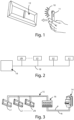
- the invention relates to an apparatus which uses the flash integrated in smartphones for sending commands and configuration parameters to the emergency lighting equipment; according to further embodiments of the apparatus, it is also possible to manage maintenance register of the systems on cloud, perform an immediate and thorough diagnosis of any fault and immediately and automatically send the request for spare parts.
- Emergency lighting equipment are devices designed for the safety of persons, which are indispensable to control the exit from premises in the case of emergency and hazardous situations in which the ordinary lighting fails.
- the installer and the maintenance technician can, thanks to an application program installed on the smartphone, communicate with new generation emergency lighting equipment, so as to transmit information to each single lamp and/or to each centralised system.
- Each lighting appliance or emergency lamp 12 can be used in the following configurations or operating mode:
- the optical communication, of the one-way type, is characterised by actuation type commands or simple configuration commands.
- the commands which can always be actuated on the lamp 12 are "operational test start”, “stop test” and “rest mode”; this basically a remote control of the test button of the lamp 12.
- optical commands relative to the "Cablecom ® optical mode" implemented in the APP are as follows:
- Each emergency lamp 12 is identified by a unique number present inside the firmware of the apparatus and inside a QR-Code 13 shown on the lamp 12; this identification code is fundamental if the emergency lamp 12 is used in the operating mode with "basic control unit” or with “advanced control unit”, as described below.
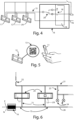
- the emergency lamps 12 are mounted on a dedicated emergency line 18, upstream of which is installed a control unit 16; the requirement to wire the lamps on the dedicated emergency line 18 is good and normal practice.
- the dedicated power supply line 18 can be fitted with a maximum of 32 lamps L1, L2,..., LN, but preferably the systems have approximately ten lamps.
- the power supply line P, N enters into the control unit 16 with the neutral N through and the phase P, alternatively, either through or switched on the low voltage bus 18, in order to manage a power of approximately 3kW for powering the lamps in ordinary operation and providing 250 mA at 12V during data transmission.
- the system is able to communicate with the lamps by means of the bus 15 which uses the emergency electrical system for data transmission (basically, a "Power over Bus” (PoB) system is adopted applied to the emergency lighting sector, with high energy available on the bus and limited costs); in particular, the control unit 16 is able to connect with the lamps switching the two power supply cables in the communication bus 15, so as to avoid any possibility of interference between the data transmission and the passage of current.
- PoB Power over Bus
- control unit 16 can consist of two embodiments: “basic control unit” and “advanced control unit”.
- the control unit 16 in the "basic control unit” version, is a module consisting of a 12 Volt power supply unit 19, a relay 20 which is able to switch the mains power supply bus (230Vac) on the communication bus (12V) and the communication and interfacing electronics consisting of buttons for actuating the various functions, configuration rotary switch and signalling LEDs ( Fig. 4 ).
- control unit 16 expands the functionalities of the "basic control unit” described above with a WI-FI communication module; in that case, by using a smartphone or tablet and using a dedicated APP, it is possible to connect to the local WI-FI network generated by the control unit 16 and thereby the control unit 16 is able to show status information for the system with details of each individual lamp, as well as receive actuation and configuration commands both broadcast and oriented to the individual lamp.
- All the lamps are fitted with a micro-switch which is able to carry out an operational diagnosis either autonomously or by receiving commands from the communication bus 15 and to communicate the test results in local mode through a code of flashes and/or colours of special status LEDs; when the control unit 16 switches the line P on the bus 15 it is able to communicate with the lamps, requesting the results of the tests or communicating set-up instructions, whilst when the lamps are connected to the communication bus 15 they can communicate to the control unit 16 the result of the tests or the status of the parameters of each lamp.
- the "basic control unit" 16 allows operational tests to be performed (tests for switching ON the emergency lamp for 30 seconds), autonomy test (tests for switching ON the emergency lamp for a predetermined duration in autonomous mode), a stop of the tests being performed and a function for inhibition of the emergency in the case of switching OFF of the system (rest mode).
- the function selected (with relative green LED switched ON) is executed by pressing "OK" on the control unit 16, whilst the outcome of the function started is shown on the status LED which switches ON red (with flashes of various durations) in the case of errors and green if there is no error.
- control unit 16 In order to carry out the configuration procedure of the system, the control unit 16 must know the number of lamps L1, L2,..., LN connected on the dedicated line before actuating any command; a preliminary configuration phase is therefore necessary in which to actuate the recognition of all the lamps.
- the installer After wiring all the emergency lamps L1, L2,..., LN, selects the configuration function and, by means of the multi-turn rotary switch of the control unit 16, defines the number of lamps present in the system, then selects the desired autonomy and selects the configuration phase by pressing "OK".
- the LED of the control unit 16 switches ON with the colour green if the number of lamps configured with the rotary selector coincides with the number of lamps which the control unit 16 has detected. If this number does not coincide, the control unit 16 sends an orange switching ON command of the signalling LED to all the lamps detected, in such a way that the lamps which remain with the steady green LED (or, possibly, steady red) can be considered as those not detected by the control unit 16 and the installer can therefore resolve any fault.
- the signalling LED can be used as a guide for searching the number of lamps connected to the control unit 16.
- control unit 16 of the "basic” type also in the case of use of the control unit 16 of the "advanced” type, the control unit must know the number of lamps L1, L2,..., LN connected on the dedicated line 18 before actuating any command.
- the installer can, anonymously (without registering), access the optical commands and can send the commands directly, in a one-way direction, as described above with regard to the "Cablecom ® optical mode".
- the advanced control unit 16 In the "Cablecom ® connect control unit management" mode, the advanced control unit 16 automatically generates a WI-FI network (in Access Point mode), to which it is possible to connect by smartphone and specific APP. Once the connection has been executed, the user will have complete control of the control unit 16 and will be able to send/receive commands and collect system data. The configurations and the commands can be performed both in broadcast mode and in individual mode (oriented to the individual lamp).
- the dedicated APP includes all the basic functions present on the user interface of the "basic" control unit, as well as the advanced functions for data collection and configuration of system and/or lamps.
- Further commands/advanced configurations available by means of the dedicated APP regard the programming of automatic tests (with definition of the periodicity and the start date of the first test and with programming which can be actuated both for the operational tests and for the autonomy tests), status of the system (summary of the data of the emergency lamps configured in the control unit, association of a test to each lamp present in the list to have a position reference of the lamp or a description which can be easily interpreted, configuration for each individual lamp present with specific parameters oriented to the individual lamp), a regular logbook of the results of the automatic tests (the user is able to download a pdf document generated following a certain periodic autonomy test or periodic operational test; the report can be saved and if necessary shared or sent via mail and contains the date and time of the data of the automatic test, type of automatic test performed, identification number and/or descriptive text of the individual lamp, fault found and/or test result).
- automatic tests with definition of the periodicity and the start date of the first test and with programming which can be actuated both for the operational tests and for the
- the Wi-Fi technology of the control unit 16 it is possible to configure the entire system, start operational tests and autonomy tests, modify the parameters of each lamp and enable advanced functionalities.
- the above-mentioned advanced functionalities include the one illustrated in detail in the appended Figure 6 ; the system layout shown highlights the simplicity of the function.
- the power supply cable 21 of the ordinary lighting the system of which comprises a protection device 22 and a control device 23 of lamps 24 for the ordinary lighting
- the control unit 16 transmits the data for the control of the emergency lamps L1, L2,... LN
- respective input connectors 25 wired between the cable 21 and the lamps L1, L2... LN it is possible, by using respective input connectors 25 wired between the cable 21 and the lamps L1, L2... LN, to activate the normal emergency operation of the lamps L1, L2...
- the bus 15 supplies the energy necessary to keep the lamp L1, L2... LN switched ON with practically infinite autonomy (possibly with a reduced luminous flow) providing there is power supply on the emergency supply line 26.
- the PoB Power over Bus
- the emergency lamps L1, L2... LN recovery function
- the battery of the lamp L1, L2... LN is flat (or broken), in order to anyway guarantee a useful service (for example, in the case of exits from premises due to night-time faults and/or on construction sites, etc.).
Landscapes
- Engineering & Computer Science (AREA)
- Computer Networks & Wireless Communication (AREA)
- Circuit Arrangement For Electric Light Sources In General (AREA)
Claims (8)
- System zur Fernsteuerung von Notbeleuchtungsausrüstung (12, L1, L2, ..., LN), wobei das System konfiguriert ist, um an ein Stromnetz (14) gekoppelt zu sein, wobei das System die Notbeleuchtungsausrüstung (12, L1, L2, ..., LN) und ein Smartphone oder Tablet (11), das mindestens einen Blitz umfasst, der konfiguriert ist, um optische Befehle in Form von kodierten Leuchtnachrichten zu senden, und ein Steuersystem, das konfiguriert ist, um von einer Softwareanwendung oder APP verwaltet zu werden, die in dem Smartphone oder Tablet (11) ausgeführt wird, und konfiguriert ist, um das Ein- und Ausschalten des mindestens einen Blitzes des Smartphones oder Tablets (11) zu modulieren, die Notbeleuchtungsausrüstung (12, L1, L2, ..., LN) umfassend eine Reihe von Notleuchten (12, L1, L2, ..., LN) und eine Zentraleinheit (16), wobei jede Notleuchte der Reihe von Notleuchten (12, L1, L2, ..., LN) konfiguriert ist, um die optischen Befehle von dem Smartphone oder Tablet (11) zu empfangen, um Funktionstests oder Fernkonfigurationen auszuführen, beides während der Installation jeder Notleuchte (12, L1, L2, ..., LN) und über eine festgelegte Zeitspanne, die mit der Wiederherstellung der Netzstromversorgung (14) jeder Notleuchte (12, L1, L2, ..., LN) beginnt, nachdem diese für eine vorher festgelegte Zeitspanne entfernt wurde, dadurch gekennzeichnet, dass: die Zentraleinheit (16) konfiguriert ist, um über eine polarisierte Versorgungsleitung (P, N) mit der Netzstromversorgung (14) gekoppelt zu sein, wobei (P, N) die Reihe von Notleuchten (12, L1, L2, ..., LN) konfiguriert ist, um an der polarisierten Versorgungsleitung (P, N) montiert zu werden, wobei die polarisierte Versorgungsleitung (P, N) konfiguriert ist, um stromaufwärts von der Zentraleinheit (16) verwaltet zu werden, wobei die Zentraleinheit (16) ferner konfiguriert ist, um Daten zu verwalten, die von der Reihe von Notlampen (12, L1, L2, ..., LN) empfangen werden, wobei die Zentraleinheit (16) ferner konfiguriert ist, um die polarisierte Versorgungsleitung (P, N) in einen Kommunikationsbus (15) zu schalten, wobei der Kommunikationsbus (15) konfiguriert ist, um die Reihe von Notleuchten (12, L1, L2, ..., LN) zu versorgen, und Daten an diese Reihe von Notleuchten (12, L1, L2, ... LN) zu übertragen, wobei die Zentraleinheit (16) eine Niederspannungsstromversorgung (19) und eine elektronische Kommunikationsschaltung umfasst, die eine Reihe von LEDs enthält, die konfiguriert sind, um einen korrekten Betrieb und/oder Fehler zu signalisieren, wobei jede Notleuchte (12, L1, L2, ... LN) einen Mikroschalter umfasst, der konfiguriert ist, um Befehle von dem Kommunikationsbus (15) zu empfangen und Signale über den korrekten Betrieb und/oder Fehler über die Signalisierungs-LEDs zu senden.
- System nach Anspruch 1, wobei die Niederspannungsstromversorgung (19) konfiguriert ist, um einen Niederspannungsbus (18) bereitzustellen, wobei die Zentraleinheit (16) ferner ein Relais (20) umfasst, das konfiguriert ist, um die polarisierte Versorgungsleitung (P, N) in den Niederspannungsbus (18) zu schalten, um dadurch den Kommunikationsbus (15) bereitzustellen.
- System nach mindestens einem der vorherigen Ansprüche, wobei das Smartphone oder Tablet (11) konfiguriert ist, um über die Softwareanwendung APP die optischen Befehle über die Zentraleinheit (16) an die Reihe von Notleuchten (12, L1, L2, ..., LN) zu senden, um Funktionstests, Autonomietests, Synchronisationstests und Tests in Bezug auf die Stunden der Notfallautonomie der Reihe von Notleuchten (12, L1, L2, ..., LN) durchzuführen.
- System nach mindestens einem der vorherigen Ansprüche, wobei jede Notleuchte (12, L1, L2, ..., LN) und/oder die Zentraleinheit (16) konfiguriert ist, dass sie durch eine eindeutige Nummer eines QR-Codes (13) identifiziert werden.
- System nach mindestens einem der vorherigen Ansprüche, wobei jede Notleuchte (12, L1, L2, ... LN) konfiguriert ist, um die optischen Befehle über die Softwareanwendung oder die APP zu empfangen, die auf dem Smartphone oder Tablet (11) läuft.
- System nach mindestens einem der vorherigen Ansprüche, wobei die Zentraleinheit (16) ferner ein WI-FI-Kommunikationsmodul umfasst, wobei die Zentraleinheit (16) konfiguriert ist, um ein lokales WI-FI-Netzwerk zu erzeugen, und wobei das Smartphone oder Tablet (11) konfiguriert ist, um mit dem lokalen WI-FI-Netzwerk unter Verwendung der Softwareanwendung oder APP, die in dem Smartphone oder Tablet (11) läuft, verbunden zu werden, sodass die Zentraleinheit (16) konfiguriert ist, um Statusinformationen der Notbeleuchtungsausrüstung (12, L1, L2, ...., LN) und jeder Notleuchte (12, L1, L2... LN) anzuzeigen, sowie Betätigungs- und Konfigurationsbefehle zu empfangen, die an die Notbeleuchtungseinrichtung (12, L1, L2, ..., LN) und/oder an jede Notleuchte (12, L1, L2, ..., LN) gerichtet sind.
- System nach Anspruch 6, wobei die Zentraleinheit (16) konfiguriert ist, um Betätigungs- und/oder Konfigurationsbefehle zu senden und zu empfangen und die Daten in Bezug auf jede Notleuchte (12, L1, L2, ..., LN) und/oder Daten in Bezug auf die Notbeleuchtungsausrüstung (12, L1, L2, ..., LN) zu erfassen, wobei die Befehle periodische automatische Testprogramme, Anlagenstatusprüfungen und periodische Sammlungen von Testergebnissen umfassen.
- System nach mindestens einem der vorherigen Ansprüche, wobei das System konfiguriert ist, um ferner mit einem normalen Beleuchtungssystem gekoppelt zu werden, umfassend Lampen (24) für die normale Beleuchtung, wobei das System ferner Eingangsverbinder (25) und ein Kabel (21) zur Stromversorgung der Lampen (24) für die normale Beleuchtung umfasst, wobei die Eingangsverbinder (25) zwischen dem Kabel (21) zur Stromversorgung der Lampen (24) für die normale Beleuchtung und jeder Notleuchte (12, L1, L2, ...LN) bereitgestellt sind, um eine Notfunktion der Reihe von Notleuchten (12, L1, L2..., LN) im Falle eines Stromausfalls eines Abschnitts des normalen Beleuchtungssystems zu aktivieren, wobei der Kommunikationsbus (15) konfiguriert ist, um Energie bereitzustellen, um mindestens eine der Reihe von Notleuchten (12, L1, L2..., LN) mit einem Nennlichtstrom während einer ersten Zeitspanne und mit einem reduzierten Lichtstrom zu versorgen, der konfiguriert ist, um am Ende der ersten Zeitspanne aktiviert zu werden.
Applications Claiming Priority (2)
| Application Number | Priority Date | Filing Date | Title |
|---|---|---|---|
| IT201900004351 | 2019-03-26 | ||
| PCT/IT2020/050060 WO2020194355A1 (en) | 2019-03-26 | 2020-03-12 | Apparatus and method for a remote control of emergency lighting equipment |
Publications (3)
| Publication Number | Publication Date |
|---|---|
| EP3949688A1 EP3949688A1 (de) | 2022-02-09 |
| EP3949688B1 true EP3949688B1 (de) | 2023-12-13 |
| EP3949688C0 EP3949688C0 (de) | 2023-12-13 |
Family
ID=67002243
Family Applications (1)
| Application Number | Title | Priority Date | Filing Date |
|---|---|---|---|
| EP20714708.3A Active EP3949688B1 (de) | 2019-03-26 | 2020-03-12 | System zur fernbedienung von notbeleuchtungsgeräten |
Country Status (4)
| Country | Link |
|---|---|
| US (1) | US20220159816A1 (de) |
| EP (1) | EP3949688B1 (de) |
| CN (1) | CN113678573A (de) |
| WO (1) | WO2020194355A1 (de) |
Families Citing this family (3)
| Publication number | Priority date | Publication date | Assignee | Title |
|---|---|---|---|---|
| CN116982408A (zh) | 2021-03-09 | 2023-10-31 | 昕诺飞控股有限公司 | 用于led管灯的辅助装置 |
| EP4064797B1 (de) * | 2021-03-26 | 2023-12-27 | Tridonic GmbH & Co KG | Kommunikations-gateway-modul |
| EP4604421A1 (de) * | 2024-02-19 | 2025-08-20 | Tridonic GmbH & Co. KG | Datenübertragungsvorrichtung, notbeleuchtungsvorrichtung und system sowie verfahren zur datenübertragung zwischen der datenübertragungsvorrichtung und der notbeleuchtungsvorrichtung |
Family Cites Families (7)
| Publication number | Priority date | Publication date | Assignee | Title |
|---|---|---|---|---|
| US7321302B2 (en) * | 2004-12-10 | 2008-01-22 | Beghelli S.P.A | Central test radio frequency system for emergency lighting |
| ITVI20040286A1 (it) * | 2004-12-10 | 2005-03-10 | Beghelli Spa | Sistema di illuminazione di emergenza a diagnosi centralizzata |
| CN103974498A (zh) * | 2013-02-05 | 2014-08-06 | 暐诗康科技有限公司 | 蜂窝式应急照明管理系统 |
| US20170006694A1 (en) * | 2014-03-13 | 2017-01-05 | Kortek Industries Pty Ltd | Wireless and Power Line Light Pairing, Dimming and Control |
| WO2016088006A1 (en) * | 2014-12-01 | 2016-06-09 | Philips Lighting Holding B.V. | Identifying and controlling signal influence on one or more properties of emitted light |
| EP3342258B1 (de) * | 2015-12-01 | 2019-06-05 | Signify Holding B.V. | Codierte lichtmodulationsanordnung |
| EP3414977B1 (de) * | 2016-02-08 | 2023-01-11 | Beghelli S.p.A. | Vorrichtung und verfahren zur fernsteuerung von beleuchtungsausrichtung |
-
2020
- 2020-03-12 EP EP20714708.3A patent/EP3949688B1/de active Active
- 2020-03-12 CN CN202080024579.9A patent/CN113678573A/zh active Pending
- 2020-03-12 WO PCT/IT2020/050060 patent/WO2020194355A1/en not_active Ceased
- 2020-03-12 US US17/593,818 patent/US20220159816A1/en not_active Abandoned
Also Published As
| Publication number | Publication date |
|---|---|
| US20220159816A1 (en) | 2022-05-19 |
| WO2020194355A1 (en) | 2020-10-01 |
| EP3949688C0 (de) | 2023-12-13 |
| EP3949688A1 (de) | 2022-02-09 |
| CN113678573A (zh) | 2021-11-19 |
Similar Documents
| Publication | Publication Date | Title |
|---|---|---|
| EP3949688B1 (de) | System zur fernbedienung von notbeleuchtungsgeräten | |
| US4945280A (en) | Independent emergency lighting system with self-diagnosis | |
| US20130138757A1 (en) | Component addition/substitution method in a home automation wireless system | |
| JPS62268646A (ja) | 印刷機に対する制御装置 | |
| GB2319373A (en) | Allocating addresses to addressable devices | |
| JPH02181599A (ja) | ビル管理コントローラ | |
| US8373569B2 (en) | Power line carrier (PLC) communication of standby generator status | |
| US20070228223A1 (en) | Device for activation and monitoring of a light-signal system for railway traffic | |
| US5982125A (en) | Automatic door test apparatus | |
| CN103207592B (zh) | 医用x光机的程控手闸装置、程控方法及专用部件 | |
| US5459450A (en) | Presence-detecting system | |
| CN112558459B (zh) | 一种电力监控系统的冗余监控装置 | |
| CN105786065B (zh) | 一种缝纫设备主控制系统 | |
| JP2002044752A (ja) | ホームコントロールシステム | |
| EP1943708B1 (de) | Notlichtsystem und beleuchtungsvorrichtungsmodul | |
| CN215340817U (zh) | 一种数控机床控制系统 | |
| KR20150134499A (ko) | 트라이플렉스 모드 기능을 제공하는 스마트 콘센트를 이용한 전원관리시스템 및 스마트 콘센트, 트라이플렉스 모드 기능을 제공하는 스마트 멀티탭을 이용한 전원관리시스템 및 스마트 멀티탭 | |
| EP3334253B1 (de) | Fernbedienungsverfahren für beleuchtungsanlagen | |
| KR101733776B1 (ko) | 3상 교류 전기기기의 유/무선 제어시스템 | |
| CN101187681B (zh) | 用于自动机构的发信号装置和控制方法 | |
| KR102296372B1 (ko) | 피난 유도 장치 및 그 동작방법 | |
| CN113472081B (zh) | 一种保护装置压板在线监测及告警装置 | |
| KR20200050073A (ko) | Plc 통신을 이용한 가로등 원격 제어시스템의 차단기 오동작 감지장치 | |
| CN111817445A (zh) | 一种停送电控制方法及系统 | |
| EP3133568B1 (de) | Automatisches feueralarmsystem und basisvorrichtung für automatisches feueralarmsystem |
Legal Events
| Date | Code | Title | Description |
|---|---|---|---|
| STAA | Information on the status of an ep patent application or granted ep patent |
Free format text: STATUS: UNKNOWN |
|
| STAA | Information on the status of an ep patent application or granted ep patent |
Free format text: STATUS: THE INTERNATIONAL PUBLICATION HAS BEEN MADE |
|
| PUAI | Public reference made under article 153(3) epc to a published international application that has entered the european phase |
Free format text: ORIGINAL CODE: 0009012 |
|
| STAA | Information on the status of an ep patent application or granted ep patent |
Free format text: STATUS: REQUEST FOR EXAMINATION WAS MADE |
|
| 17P | Request for examination filed |
Effective date: 20210708 |
|
| AK | Designated contracting states |
Kind code of ref document: A1 Designated state(s): AL AT BE BG CH CY CZ DE DK EE ES FI FR GB GR HR HU IE IS IT LI LT LU LV MC MK MT NL NO PL PT RO RS SE SI SK SM TR |
|
| DAV | Request for validation of the european patent (deleted) | ||
| DAX | Request for extension of the european patent (deleted) | ||
| P01 | Opt-out of the competence of the unified patent court (upc) registered |
Effective date: 20230512 |
|
| GRAP | Despatch of communication of intention to grant a patent |
Free format text: ORIGINAL CODE: EPIDOSNIGR1 |
|
| STAA | Information on the status of an ep patent application or granted ep patent |
Free format text: STATUS: GRANT OF PATENT IS INTENDED |
|
| INTG | Intention to grant announced |
Effective date: 20230814 |
|
| GRAS | Grant fee paid |
Free format text: ORIGINAL CODE: EPIDOSNIGR3 |
|
| GRAA | (expected) grant |
Free format text: ORIGINAL CODE: 0009210 |
|
| STAA | Information on the status of an ep patent application or granted ep patent |
Free format text: STATUS: THE PATENT HAS BEEN GRANTED |
|
| AK | Designated contracting states |
Kind code of ref document: B1 Designated state(s): AL AT BE BG CH CY CZ DE DK EE ES FI FR GB GR HR HU IE IS IT LI LT LU LV MC MK MT NL NO PL PT RO RS SE SI SK SM TR |
|
| REG | Reference to a national code |
Ref country code: GB Ref legal event code: FG4D |
|
| REG | Reference to a national code |
Ref country code: CH Ref legal event code: EP |
|
| REG | Reference to a national code |
Ref country code: DE Ref legal event code: R096 Ref document number: 602020022668 Country of ref document: DE |
|
| REG | Reference to a national code |
Ref country code: IE Ref legal event code: FG4D |
|
| U01 | Request for unitary effect filed |
Effective date: 20231220 |
|
| U07 | Unitary effect registered |
Designated state(s): AT BE BG DE DK EE FI FR IT LT LU LV MT NL PT SE SI Effective date: 20240103 |
|
| P04 | Withdrawal of opt-out of the competence of the unified patent court (upc) registered |
Effective date: 20231222 |
|
| PG25 | Lapsed in a contracting state [announced via postgrant information from national office to epo] |
Ref country code: GR Free format text: LAPSE BECAUSE OF FAILURE TO SUBMIT A TRANSLATION OF THE DESCRIPTION OR TO PAY THE FEE WITHIN THE PRESCRIBED TIME-LIMIT Effective date: 20240314 |
|
| U20 | Renewal fee for the european patent with unitary effect paid |
Year of fee payment: 5 Effective date: 20240318 |
|
| PG25 | Lapsed in a contracting state [announced via postgrant information from national office to epo] |
Ref country code: ES Free format text: LAPSE BECAUSE OF FAILURE TO SUBMIT A TRANSLATION OF THE DESCRIPTION OR TO PAY THE FEE WITHIN THE PRESCRIBED TIME-LIMIT Effective date: 20231213 |
|
| PG25 | Lapsed in a contracting state [announced via postgrant information from national office to epo] |
Ref country code: GR Free format text: LAPSE BECAUSE OF FAILURE TO SUBMIT A TRANSLATION OF THE DESCRIPTION OR TO PAY THE FEE WITHIN THE PRESCRIBED TIME-LIMIT Effective date: 20240314 Ref country code: ES Free format text: LAPSE BECAUSE OF FAILURE TO SUBMIT A TRANSLATION OF THE DESCRIPTION OR TO PAY THE FEE WITHIN THE PRESCRIBED TIME-LIMIT Effective date: 20231213 |
|
| PG25 | Lapsed in a contracting state [announced via postgrant information from national office to epo] |
Ref country code: RS Free format text: LAPSE BECAUSE OF FAILURE TO SUBMIT A TRANSLATION OF THE DESCRIPTION OR TO PAY THE FEE WITHIN THE PRESCRIBED TIME-LIMIT Effective date: 20231213 Ref country code: NO Free format text: LAPSE BECAUSE OF FAILURE TO SUBMIT A TRANSLATION OF THE DESCRIPTION OR TO PAY THE FEE WITHIN THE PRESCRIBED TIME-LIMIT Effective date: 20240313 Ref country code: HR Free format text: LAPSE BECAUSE OF FAILURE TO SUBMIT A TRANSLATION OF THE DESCRIPTION OR TO PAY THE FEE WITHIN THE PRESCRIBED TIME-LIMIT Effective date: 20231213 |
|
| PG25 | Lapsed in a contracting state [announced via postgrant information from national office to epo] |
Ref country code: IS Free format text: LAPSE BECAUSE OF FAILURE TO SUBMIT A TRANSLATION OF THE DESCRIPTION OR TO PAY THE FEE WITHIN THE PRESCRIBED TIME-LIMIT Effective date: 20240413 |
|
| PG25 | Lapsed in a contracting state [announced via postgrant information from national office to epo] |
Ref country code: CZ Free format text: LAPSE BECAUSE OF FAILURE TO SUBMIT A TRANSLATION OF THE DESCRIPTION OR TO PAY THE FEE WITHIN THE PRESCRIBED TIME-LIMIT Effective date: 20231213 |
|
| PG25 | Lapsed in a contracting state [announced via postgrant information from national office to epo] |
Ref country code: SK Free format text: LAPSE BECAUSE OF FAILURE TO SUBMIT A TRANSLATION OF THE DESCRIPTION OR TO PAY THE FEE WITHIN THE PRESCRIBED TIME-LIMIT Effective date: 20231213 |
|
| PG25 | Lapsed in a contracting state [announced via postgrant information from national office to epo] |
Ref country code: SM Free format text: LAPSE BECAUSE OF FAILURE TO SUBMIT A TRANSLATION OF THE DESCRIPTION OR TO PAY THE FEE WITHIN THE PRESCRIBED TIME-LIMIT Effective date: 20231213 Ref country code: SK Free format text: LAPSE BECAUSE OF FAILURE TO SUBMIT A TRANSLATION OF THE DESCRIPTION OR TO PAY THE FEE WITHIN THE PRESCRIBED TIME-LIMIT Effective date: 20231213 Ref country code: RO Free format text: LAPSE BECAUSE OF FAILURE TO SUBMIT A TRANSLATION OF THE DESCRIPTION OR TO PAY THE FEE WITHIN THE PRESCRIBED TIME-LIMIT Effective date: 20231213 Ref country code: IS Free format text: LAPSE BECAUSE OF FAILURE TO SUBMIT A TRANSLATION OF THE DESCRIPTION OR TO PAY THE FEE WITHIN THE PRESCRIBED TIME-LIMIT Effective date: 20240413 Ref country code: CZ Free format text: LAPSE BECAUSE OF FAILURE TO SUBMIT A TRANSLATION OF THE DESCRIPTION OR TO PAY THE FEE WITHIN THE PRESCRIBED TIME-LIMIT Effective date: 20231213 |
|
| PG25 | Lapsed in a contracting state [announced via postgrant information from national office to epo] |
Ref country code: PL Free format text: LAPSE BECAUSE OF FAILURE TO SUBMIT A TRANSLATION OF THE DESCRIPTION OR TO PAY THE FEE WITHIN THE PRESCRIBED TIME-LIMIT Effective date: 20231213 |
|
| PG25 | Lapsed in a contracting state [announced via postgrant information from national office to epo] |
Ref country code: PL Free format text: LAPSE BECAUSE OF FAILURE TO SUBMIT A TRANSLATION OF THE DESCRIPTION OR TO PAY THE FEE WITHIN THE PRESCRIBED TIME-LIMIT Effective date: 20231213 |
|
| REG | Reference to a national code |
Ref country code: DE Ref legal event code: R097 Ref document number: 602020022668 Country of ref document: DE |
|
| PLBE | No opposition filed within time limit |
Free format text: ORIGINAL CODE: 0009261 |
|
| STAA | Information on the status of an ep patent application or granted ep patent |
Free format text: STATUS: NO OPPOSITION FILED WITHIN TIME LIMIT |
|
| REG | Reference to a national code |
Ref country code: CH Ref legal event code: PL |
|
| 26N | No opposition filed |
Effective date: 20240916 |
|
| PG25 | Lapsed in a contracting state [announced via postgrant information from national office to epo] |
Ref country code: MC Free format text: LAPSE BECAUSE OF FAILURE TO SUBMIT A TRANSLATION OF THE DESCRIPTION OR TO PAY THE FEE WITHIN THE PRESCRIBED TIME-LIMIT Effective date: 20231213 |
|
| PG25 | Lapsed in a contracting state [announced via postgrant information from national office to epo] |
Ref country code: MC Free format text: LAPSE BECAUSE OF FAILURE TO SUBMIT A TRANSLATION OF THE DESCRIPTION OR TO PAY THE FEE WITHIN THE PRESCRIBED TIME-LIMIT Effective date: 20231213 |
|
| P05 | Withdrawal of opt-out of the competence of the unified patent court (upc) changed |
Free format text: CASE NUMBER: APP_597261/2023 Effective date: 20240103 |
|
| PG25 | Lapsed in a contracting state [announced via postgrant information from national office to epo] |
Ref country code: IE Free format text: LAPSE BECAUSE OF NON-PAYMENT OF DUE FEES Effective date: 20240312 |
|
| PG25 | Lapsed in a contracting state [announced via postgrant information from national office to epo] |
Ref country code: IE Free format text: LAPSE BECAUSE OF NON-PAYMENT OF DUE FEES Effective date: 20240312 Ref country code: CH Free format text: LAPSE BECAUSE OF NON-PAYMENT OF DUE FEES Effective date: 20240331 |
|
| U20 | Renewal fee for the european patent with unitary effect paid |
Year of fee payment: 6 Effective date: 20250304 |
|
| PGFP | Annual fee paid to national office [announced via postgrant information from national office to epo] |
Ref country code: GB Payment date: 20250324 Year of fee payment: 6 |
|
| PG25 | Lapsed in a contracting state [announced via postgrant information from national office to epo] |
Ref country code: CY Free format text: LAPSE BECAUSE OF FAILURE TO SUBMIT A TRANSLATION OF THE DESCRIPTION OR TO PAY THE FEE WITHIN THE PRESCRIBED TIME-LIMIT; INVALID AB INITIO Effective date: 20200312 |
|
| PG25 | Lapsed in a contracting state [announced via postgrant information from national office to epo] |
Ref country code: HU Free format text: LAPSE BECAUSE OF FAILURE TO SUBMIT A TRANSLATION OF THE DESCRIPTION OR TO PAY THE FEE WITHIN THE PRESCRIBED TIME-LIMIT; INVALID AB INITIO Effective date: 20200312 |
|
| PG25 | Lapsed in a contracting state [announced via postgrant information from national office to epo] |
Ref country code: TR Free format text: LAPSE BECAUSE OF FAILURE TO SUBMIT A TRANSLATION OF THE DESCRIPTION OR TO PAY THE FEE WITHIN THE PRESCRIBED TIME-LIMIT Effective date: 20231213 |