EP4064797B1 - Kommunikations-gateway-modul - Google Patents
Kommunikations-gateway-modul Download PDFInfo
- Publication number
- EP4064797B1 EP4064797B1 EP21165124.5A EP21165124A EP4064797B1 EP 4064797 B1 EP4064797 B1 EP 4064797B1 EP 21165124 A EP21165124 A EP 21165124A EP 4064797 B1 EP4064797 B1 EP 4064797B1
- Authority
- EP
- European Patent Office
- Prior art keywords
- gateway module
- communication gateway
- bus
- terminals
- dali
- Prior art date
- Legal status (The legal status is an assumption and is not a legal conclusion. Google has not performed a legal analysis and makes no representation as to the accuracy of the status listed.)
- Active
Links
Images


Classifications
-
- H—ELECTRICITY
- H05—ELECTRIC TECHNIQUES NOT OTHERWISE PROVIDED FOR
- H05B—ELECTRIC HEATING; ELECTRIC LIGHT SOURCES NOT OTHERWISE PROVIDED FOR; CIRCUIT ARRANGEMENTS FOR ELECTRIC LIGHT SOURCES, IN GENERAL
- H05B47/00—Circuit arrangements for operating light sources in general, i.e. where the type of light source is not relevant
- H05B47/10—Controlling the light source
- H05B47/175—Controlling the light source by remote control
- H05B47/18—Controlling the light source by remote control via data-bus transmission
-
- H—ELECTRICITY
- H05—ELECTRIC TECHNIQUES NOT OTHERWISE PROVIDED FOR
- H05B—ELECTRIC HEATING; ELECTRIC LIGHT SOURCES NOT OTHERWISE PROVIDED FOR; CIRCUIT ARRANGEMENTS FOR ELECTRIC LIGHT SOURCES, IN GENERAL
- H05B47/00—Circuit arrangements for operating light sources in general, i.e. where the type of light source is not relevant
- H05B47/10—Controlling the light source
- H05B47/175—Controlling the light source by remote control
- H05B47/19—Controlling the light source by remote control via wireless transmission
-
- H—ELECTRICITY
- H05—ELECTRIC TECHNIQUES NOT OTHERWISE PROVIDED FOR
- H05B—ELECTRIC HEATING; ELECTRIC LIGHT SOURCES NOT OTHERWISE PROVIDED FOR; CIRCUIT ARRANGEMENTS FOR ELECTRIC LIGHT SOURCES, IN GENERAL
- H05B47/00—Circuit arrangements for operating light sources in general, i.e. where the type of light source is not relevant
- H05B47/10—Controlling the light source
- H05B47/175—Controlling the light source by remote control
- H05B47/18—Controlling the light source by remote control via data-bus transmission
- H05B47/183—Controlling the light source by remote control via data-bus transmission using digital addressable lighting interface [DALI] communication protocols
Definitions
- the invention relates, in general, to LED lighting wireless control modules.
- the invention relates to a communication gateway module for translating between a wired (e.g.) DALI bus communication and a (non-DALI) wireless communication.
- LED drivers which comprise a control interface, allow their light output to be dynamically controlled.
- the DALI control interface is one of the most common control interfaces used in LED lighting.
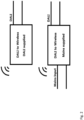
- a DALI interface allows a digital signal to be sent over two wires from a controller to a LED driver (see Fig. 1(a) ).
- the DALI control interface can be extended to include wireless devices as well.
- the two wires interface can be replaced by a wireless intermediate gateway, as shown in Fig. 1(b) .
- Fig. 1(a) only the DALI wires are represented. However, most of the devices in the market are powered either via the DALI wires themselves or they possess their own power supply, for example from a mains converter (see Fig. 2 ).
- Devices with internal power supply may or may not have integrated DALI power supply.
- Devices with integrated DALI power supply provide energy to the DALI bus exclusively or in conjunction with another DALI power supply.
- the only restriction imposed by DALI in terms of paralleling DALI power supplies is that the total current circulating on the DALI bus cannot exceed the bus limit or 250 mA and the peak transient current of 450 mA. So, multiple power supplies can provide energy to the same bus.
- WO 2020/194355 A1 and GB 2554987 A respectively disclose a communication gateway module being capable of powering light fixtures from two different sources of electrical power.
- the invention relates to a communication gateway module having: a wireless interface, a wired bus interface comprising wired bus terminals, e.g. a DALI bus interface, a mains supply interface comprising mains voltage terminals; and a control circuit.
- the control circuit is configured to determine whether a mains voltage is supplied to the mains supply terminals and to power the gateway module in the positive case, and to determine whether a bus with non-zero quiescent state, such as e.g. a DALI bus, is connected to the wired bus terminals, and to power the gateway module off the wired bus terminals in case no mains voltage is supplied at mains voltage terminals.
- gateway module can be powered both by the mains supply or the wired bus interface, e.g. a DALI power supply.
- the communication gateway module further comprises a bus voltage supply unit for supplying the bus at the wired bus terminals with electrical power off the mains voltage terminals.
- the communication gateway module comprises a first current limiting circuit configured to limit any current drawn from the wired bus terminals.
- the communication gateway module comprises a second current limiting circuitry configured to limit any current supplied to the wired bus terminals.
- the communication gateway module comprises a circuitry for commutating the polarity of the voltage of the electrical power supplied to the bus at the wired bus terminals.
- the communication gateway module comprises an inverting stage configured to operate as a rectifier when supply is drawn from the bus terminals.
- the invention relates to an LED lighting system.
- the LED lighting system comprises a communication gateway module of the first aspect or any of its embodiments, and an LED driver.
- the invention relates to an LED luminaire.
- the luminaire comprises a communication gateway module of the first aspect or any of its embodiments; an LED driver; and a light source comprising one or more LEDs or OLEDs, the light source being operable by the LED driver.
- LED luminaire shall mean a luminaire with a light source comprising one or more LEDs or OLEDs. LEDs are well-known in the art, and therefore, will only briefly be discussed to provide a complete description of the invention.
- the aspect of the present invention might contain integrated circuits that are readily manufacturable using conventional semiconductor technologies, such as complementary metal-oxide semiconductor technology, short "CMOS".
- CMOS complementary metal-oxide semiconductor technology
- the aspects of the present invention may be implemented with other manufacturing processes for making optical as well as electrical devices.
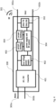
- a communication gateway module 300 is shown according to an embodiment.
- the communication gateway module 300 comprises a wireless interface 301 (antenna not shown), a wired bus interface 302 comprising wired bus terminals 302a, 302b, e.g. a DALI bus interface, a mains supply interface 303 comprising mains voltage terminals 303a, 303b; and a control circuit 304.
- the control circuit 304 controls the power supply of the communication gateway module 300 and the communication over the interfaces 301 and 302.
- the control circuit is connected to the interfaces 301, 302 and the mains supply interface 303.
- the communication gateway module 300 is configured to determine whether a mains voltage is supplied to the mains supply terminals 303a, 303b and to power the gateway module 300 in the positive case.
- the communication gateway module 300 is configured to determine whether a bus with non-zero quiescent state is connected to the wired bus terminals 302a, 302b, and to power the gateway module 300 off the wired bus terminals 302a, 302b in case no mains voltage is supplied at mains voltage terminals 303a, 303b.
- the communication gateway module 300 is configured to select its power source regardless of the sources available, DALI, internal power supply or both.
- the communication gateway module 300 can draw limited power from the DALI bus (limited meaning within the limitations of the DALI specification).
- the communication gateway module 300 is provided with mains supply terminals 303a and 303b.
- the control circuit 304 in the communication gateway module 300 can determine whether mains and/or DALI power supply is available at the respective terminals. In case mains power supply is available, the priority is on the mains power supply.
- the communication gateway module 300 is configured to select the supply source according to any one of the combinations shown in the table below and can possess an integrated DALI Power Supply (IDPS), see circuit 403 on Figure 4 , as well.
- IDPS integrated DALI Power Supply
- the communication gateway module 300 is provided with a circuitry to power the DALI bus, provided that it is itself provided with mains supply voltage.
- Fig. 4 shows a communication gateway module 300 according to an embodiment.
- an AC/DC converter 401 is arranged for being supplied with AC mains voltage from the terminals 303a and 303b and for outputting a DC voltage.
- the DV voltage is supplied e.g. to a low voltage power supply unit 402. Moreover, it provides energy to the control circuit 304 and its IDPS designated.
- the low voltage power supply (LVPS) 402 is configured to power the control circuit 304, off the DC voltage supplied by the AC/DC converter (401).
- the control circuit 304 may comprise a microcontroller and RF transceiver, both of which can be integrated as system-on-chip (SoC).
- a first current limiting circuit 403 is connected directly to the output of the AC/DC converter 401 and represents the IDPS according to this embodiment. It can be configured to limit the amount of current provided to the DALI bus according to the DALI specification.
- a second current limiting circuitry 404 limits the current in opposite direction to the first one, limiting the amount of current drawn from the DALI bus, when the DALI bus is used as main power source. Both circuits can be controllable by the control circuit 304 such that the control circuit can e.g. also disable them.
- Both current limiting circuitries can be bypassed by a semiconductor (e.g. diode) in anti-parallel position, to allow the current to flow in both directions.
- a semiconductor e.g. diode
- the control circuit 304 has a power supply and a RF control responsible for the DALI communications, RF communications and the control of the current limiting circuits 403, 404.
- a DALI TX and DALI RX interface 302 is is configured to receive and transmit according to DALI specifications. It is controlled by the control unit 304.
- Fig. 5 shows a flow chart 500 of an operation of the communication gateway module 300 according to an embodiment.
- step 504 it is checked if the mains voltage is present at the mains terminals. If yes, then in step 505 it is checked for an external power supply supplying the DALI bus with power. In particular, it is checked in step 508 if the DALI bus is high. If yes, then a configuration of the system or the communication gateway module 300 is checked in step 509. In particular, a user input can be used to determine whether the internal power supply IDPS of the communication gateway module 300 should or should not operate when the DALI bus is already powered. This ability provides flexibility to scale up the power of the communication gateway module 300 or to avoid exceeding the DALI system requirements. This input can be in many forms, such as configuration file, settings, button in interface, etc. Afterwards, it is checked if there is a multi-power supplied system in step 510. If yes, then the IDPS is enabled in step 507 and the DALI wireless gateway functions are resumed in step 506.
- step 504 If the mains is not present in step 504, then the communication gateway module 300 is powered by DALI supply in step 503 and the DALI wireless gateway functions are resumed in step 506.
- step 508 if the DALI bus is not high in step 508, then the IDPS is enabled in step 507 and, afterwards, the DALI wireless gateway functions are resumed in step 506.
- step510 the system or communication gateway module 300 is not a multi-power supplied system, then the DALI wireless gateway functions are resumed in step506.
- Fig. 6 shows the first current limiting circuit 403 and the second current limiting circuit 404 of a communication gateway module 300 according to an embodiment.
- the AC/DC converter 401 comprises a flyback converter for supplying a regulated DC voltage at a capacitor C1.
- the elements D7, R2, Q1, Q2, R1, D1, Q5 and VCTRL1 are part of DALI power supply and are used when the communication gateway module 300 is mains supplied and supplies DALI bus.
- the elements D6, R3, Q3, Q4, R5, D2, Q6, R4 and Q11 are part of the circuit used when the communication gateway module 300 is supplied by a DALI bus.
- the commands VCTRL1 and VCTRL2 are controller signals that are configured to enable and disable the current limiting circuits 403 and 404 depending on the mode of operation.
- the command VCTRL1 enables the DALI power supply when the communication gateway module 300 is mains supplied, while the command VCTRL2 disables the current limiting circuit 403 and 404 when the communication gateway module 300 is mains supplied.
- the command VCTRL1 disables the DALI power supply, while, when DALI bus power is supplied, the current limiting circuit 404 is automatically enabled via R4 and Q6 and can only be disabled via the command VCTRL2.
- Fig. 7 shows a first current limiting circuit 403, a second current limiting circuit 404 and an inverter/rectifying circuit 601 of a communication gateway module 300 according to an embodiment.
- the inverting stage 601 is added to the previous embodiment shown in Fig. 6 .
- the inverting/rectifying section 601 of the circuit allows any DALI polarity on the DALI bus by enabling Q7 and Q10 or Q8 and Q9 pairs.
- the DALI voltage polarity can be adjusted to match other power supplies on the bus, if existing.
- the diodes D4, D5, D8 and D9 rectify the DALI input voltage to allow any wire polarity connection.
- the inverter/rectifier circuitry 601 allows to switch the polarity of the voltage supplied to the DALI bus terminals 302a and 302b.
- LED lighting system and an LED luminaire according to an embodiments.
- the LED lighting system comprises a communication gateway module 300 according to an embodiment; and an LED driver.
- the LED luminaire comprises a communication gateway module 300 according to an embodiment; an LED driver; and a light source comprising one or more LEDs or OLEDs.
- the light source is operable by the LED driver.
Landscapes
- Engineering & Computer Science (AREA)
- Computer Networks & Wireless Communication (AREA)
- Small-Scale Networks (AREA)
- Remote Monitoring And Control Of Power-Distribution Networks (AREA)
Claims (8)
- Kommunikations-Gateway-Modul (300), das aufweist:- eine drahtlose Schnittstelle (301),- eine drahtgebundene Busschnittstelle (302), umfassend drahtgebundene Busanschlüsse (302a, 302b), z. B. eine DALI-Bus-Schnittstelle,- eine Netzversorgungsschnittstelle (303), umfassend Netzspannungsanschlüsse (303a, 303b); und gekennzeichnet durch- eine Steuerschaltung (304), die konfiguriert ist zum:- Bestimmen, ob die Netzversorgungsanschlüsse (303a, 303b) mit einer Netzspannung versorgt werden und um das Gateway-Modul (300) aus den Netzversorgungsanschlüssen (303a, 303b) in dem positiven Fall anzutreiben, und zum- Bestimmen, ob ein Bus mit einem Ruhezustand ungleich Null mit den drahtgebundenen Busanschlüssen (302a, 302b) verbunden ist und, falls ja, um das Gateway-Modul (300) aus den drahtgebundenen Busanschlüssen (302a, 302b), für den Fall, dass mit keiner Netzspannung an den Netzspannungsanschlüssen (303a, 303b) versorgt wird, anzutreiben.
- Kommunikations-Gateway-Modul (300) nach Anspruch 1, ferner umfassend eine Busspannungsversorgungseinheit zum Versorgen des Busses an den drahtgebundenen Busanschlüssen (302a, 302b) mit einer elektrischen Leistung von den Netzspannungsanschlüssen (303a, 303b).
- Kommunikations-Gateway-Modul (300) nach Anspruch 1 oder 2, umfassend eine erste Strombegrenzungsschaltung (403), die konfiguriert ist, um einen beliebigen Strom, mit dem durch das Kommunikations-Gateway-Modul (300) an die drahtgebundenen Busanschlüsse (302a, 302b) versorgt wird, zu begrenzen.
- Kommunikations-Gateway-Modul (300) nach Anspruch 2, ferner umfassend eine zweite Strombegrenzungsschaltlogik (404), die konfiguriert ist, um den beliebigen Strom, der durch das Kommunikations-Gateway-Modul (300) aus den drahtgebundenen Busanschlüssen (302a, 302b) gezogen wird, zu begrenzen.
- Kommunikations-Gateway-Modul (300) nach einem der Ansprüche 2 oder 4, ferner umfassend eine Schaltlogik zum Kommutieren der Polarität der Spannung der elektrischen Leistung, mit der der Bus an den drahtgebundenen Busanschlüssen (302a, 302b) versorgt wird.
- Kommunikations-Gateway-Modul (300) nach einem der vorstehenden Ansprüche, ferner umfassend eine invertierende Stufe (601), die konfiguriert ist, um als ein Gleichrichter zu arbeiten, wenn die Leistung aus den Busanschlüssen (302a, 302b) durch das Kommunikations-Gateway-Modul (300) gezogen wird.
- LED-Beleuchtungssystem, umfassenddas Kommunikations-Gateway-Modul (300) nach einem der Ansprüche 1 bis 6; undeinen LED-Treiber.
- LED-Leuchte, umfassenddas Kommunikations-Gateway-Modul (300) nach einem der Ansprüche 1 bis 6;einen LED-Treiber; undeine Lichtquelle, umfassend eine oder mehrere LEDs oder OLEDs, wobei die Lichtquelle durch den LED-Treiber betriebsfähig ist.
Priority Applications (2)
| Application Number | Priority Date | Filing Date | Title |
|---|---|---|---|
| EP21165124.5A EP4064797B1 (de) | 2021-03-26 | 2021-03-26 | Kommunikations-gateway-modul |
| PCT/EP2022/057511 WO2022200361A1 (en) | 2021-03-26 | 2022-03-22 | Communication gateway module |
Applications Claiming Priority (1)
| Application Number | Priority Date | Filing Date | Title |
|---|---|---|---|
| EP21165124.5A EP4064797B1 (de) | 2021-03-26 | 2021-03-26 | Kommunikations-gateway-modul |
Publications (2)
| Publication Number | Publication Date |
|---|---|
| EP4064797A1 EP4064797A1 (de) | 2022-09-28 |
| EP4064797B1 true EP4064797B1 (de) | 2023-12-27 |
Family
ID=75252356
Family Applications (1)
| Application Number | Title | Priority Date | Filing Date |
|---|---|---|---|
| EP21165124.5A Active EP4064797B1 (de) | 2021-03-26 | 2021-03-26 | Kommunikations-gateway-modul |
Country Status (2)
| Country | Link |
|---|---|
| EP (1) | EP4064797B1 (de) |
| WO (1) | WO2022200361A1 (de) |
Family Cites Families (3)
| Publication number | Priority date | Publication date | Assignee | Title |
|---|---|---|---|---|
| AT14699U1 (de) * | 2014-10-30 | 2016-04-15 | Tridonic Gmbh & Co Kg | Verfahren zur Ansteuerung für ein Betriebsgerät für Leuchtmittel |
| GB2554987A (en) * | 2016-08-19 | 2018-04-18 | Leviton Manufacturing Co | Supplemental power system for power over ethernet lighting luminaries |
| EP3949688B1 (de) * | 2019-03-26 | 2023-12-13 | Beghelli S.p.A. | System zur fernbedienung von notbeleuchtungsgeräten |
-
2021
- 2021-03-26 EP EP21165124.5A patent/EP4064797B1/de active Active
-
2022
- 2022-03-22 WO PCT/EP2022/057511 patent/WO2022200361A1/en not_active Ceased
Also Published As
| Publication number | Publication date |
|---|---|
| WO2022200361A1 (en) | 2022-09-29 |
| EP4064797A1 (de) | 2022-09-28 |
Similar Documents
| Publication | Publication Date | Title |
|---|---|---|
| CN111052864B (zh) | 向照明设备的部件供电的电路以及包括该电路的照明设备 | |
| EP3504936B1 (de) | Steuerung einer isolierten hilfsstromversorgung und dali-versorgung für sr-led-treiber | |
| TWI578843B (zh) | 發光二極體驅動電路 | |
| US10749340B2 (en) | Power switch with power harvesting for local controller | |
| KR101790046B1 (ko) | 보조배터리를 이용한 마스터장치의 충전장치 및 방법 | |
| EP2815492B1 (de) | Lasttreiber und verfahren zur verringerung des ausgangswelligkeitsstroms eines lasttreibers | |
| CN204707310U (zh) | 多路调光装置及应用其的照明装置 | |
| TWI426826B (zh) | 燈具之驅動控制電路 | |
| EP4064797B1 (de) | Kommunikations-gateway-modul | |
| EP3057213A1 (de) | Vorrichtung zum ausführen einer hybriden leistungsregelung in einer elektronischen vorrichtung mit hilfe eines getrennten ausgangsleistungsknotens zur mehrzweckverwendung von auftrieb | |
| US12526888B2 (en) | Control integrated circuit for controlling an operating device for lighting means; operating device; luminaire and method for operating a control integrated circuit | |
| US9693404B1 (en) | Negative current sensing method for multi-channel LED driver | |
| CN209982778U (zh) | 智能化cob光引擎模组 | |
| EP3755123B1 (de) | Kommunikationsschnittstelle für beleuchtungsmittel | |
| CN114786292A (zh) | 一种用于大功率电源解决电路中的异常测试控制电路 | |
| US11317494B2 (en) | Linear luminance adjusting circuit | |
| US11765802B2 (en) | Isolated primary side switched converter for LED loads | |
| CN110771262B (zh) | 用于提供功率转换器的装置和系统 | |
| KR102142638B1 (ko) | 전류 경로 전환에 기초하여 동작하는 조명 기기 | |
| JP2022509651A (ja) | Led照明ユニットのための電源 | |
| CN222283522U (zh) | 一种应用于led照明装置的驱动电路 | |
| CN212393020U (zh) | 一种智能照明装置 | |
| CN206596272U (zh) | 一种新型led驱动模块 | |
| CN115209590A (zh) | 用于照明装置的操作设备 | |
| TR201712454A2 (tr) | Dali protokolünü destekleyen led sürücü devresi̇ |
Legal Events
| Date | Code | Title | Description |
|---|---|---|---|
| PUAI | Public reference made under article 153(3) epc to a published international application that has entered the european phase |
Free format text: ORIGINAL CODE: 0009012 |
|
| STAA | Information on the status of an ep patent application or granted ep patent |
Free format text: STATUS: THE APPLICATION HAS BEEN PUBLISHED |
|
| AK | Designated contracting states |
Kind code of ref document: A1 Designated state(s): AL AT BE BG CH CY CZ DE DK EE ES FI FR GB GR HR HU IE IS IT LI LT LU LV MC MK MT NL NO PL PT RO RS SE SI SK SM TR |
|
| STAA | Information on the status of an ep patent application or granted ep patent |
Free format text: STATUS: REQUEST FOR EXAMINATION WAS MADE |
|
| 17P | Request for examination filed |
Effective date: 20230125 |
|
| RBV | Designated contracting states (corrected) |
Designated state(s): AL AT BE BG CH CY CZ DE DK EE ES FI FR GB GR HR HU IE IS IT LI LT LU LV MC MK MT NL NO PL PT RO RS SE SI SK SM TR |
|
| GRAP | Despatch of communication of intention to grant a patent |
Free format text: ORIGINAL CODE: EPIDOSNIGR1 |
|
| STAA | Information on the status of an ep patent application or granted ep patent |
Free format text: STATUS: GRANT OF PATENT IS INTENDED |
|
| INTG | Intention to grant announced |
Effective date: 20230831 |
|
| GRAS | Grant fee paid |
Free format text: ORIGINAL CODE: EPIDOSNIGR3 |
|
| GRAA | (expected) grant |
Free format text: ORIGINAL CODE: 0009210 |
|
| STAA | Information on the status of an ep patent application or granted ep patent |
Free format text: STATUS: THE PATENT HAS BEEN GRANTED |
|
| AK | Designated contracting states |
Kind code of ref document: B1 Designated state(s): AL AT BE BG CH CY CZ DE DK EE ES FI FR GB GR HR HU IE IS IT LI LT LU LV MC MK MT NL NO PL PT RO RS SE SI SK SM TR |
|
| REG | Reference to a national code |
Ref country code: GB Ref legal event code: FG4D |
|
| REG | Reference to a national code |
Ref country code: DE Ref legal event code: R084 Ref document number: 602021007990 Country of ref document: DE Ref country code: CH Ref legal event code: EP |
|
| P01 | Opt-out of the competence of the unified patent court (upc) registered |
Effective date: 20231130 |
|
| REG | Reference to a national code |
Ref country code: DE Ref legal event code: R096 Ref document number: 602021007990 Country of ref document: DE |
|
| REG | Reference to a national code |
Ref country code: IE Ref legal event code: FG4D |
|
| PG25 | Lapsed in a contracting state [announced via postgrant information from national office to epo] |
Ref country code: GR Free format text: LAPSE BECAUSE OF FAILURE TO SUBMIT A TRANSLATION OF THE DESCRIPTION OR TO PAY THE FEE WITHIN THE PRESCRIBED TIME-LIMIT Effective date: 20240328 |
|
| REG | Reference to a national code |
Ref country code: LT Ref legal event code: MG9D |
|
| PG25 | Lapsed in a contracting state [announced via postgrant information from national office to epo] |
Ref country code: LT Free format text: LAPSE BECAUSE OF FAILURE TO SUBMIT A TRANSLATION OF THE DESCRIPTION OR TO PAY THE FEE WITHIN THE PRESCRIBED TIME-LIMIT Effective date: 20231227 |
|
| PG25 | Lapsed in a contracting state [announced via postgrant information from national office to epo] |
Ref country code: ES Free format text: LAPSE BECAUSE OF FAILURE TO SUBMIT A TRANSLATION OF THE DESCRIPTION OR TO PAY THE FEE WITHIN THE PRESCRIBED TIME-LIMIT Effective date: 20231227 |
|
| PG25 | Lapsed in a contracting state [announced via postgrant information from national office to epo] |
Ref country code: LT Free format text: LAPSE BECAUSE OF FAILURE TO SUBMIT A TRANSLATION OF THE DESCRIPTION OR TO PAY THE FEE WITHIN THE PRESCRIBED TIME-LIMIT Effective date: 20231227 Ref country code: GR Free format text: LAPSE BECAUSE OF FAILURE TO SUBMIT A TRANSLATION OF THE DESCRIPTION OR TO PAY THE FEE WITHIN THE PRESCRIBED TIME-LIMIT Effective date: 20240328 Ref country code: FI Free format text: LAPSE BECAUSE OF FAILURE TO SUBMIT A TRANSLATION OF THE DESCRIPTION OR TO PAY THE FEE WITHIN THE PRESCRIBED TIME-LIMIT Effective date: 20231227 Ref country code: ES Free format text: LAPSE BECAUSE OF FAILURE TO SUBMIT A TRANSLATION OF THE DESCRIPTION OR TO PAY THE FEE WITHIN THE PRESCRIBED TIME-LIMIT Effective date: 20231227 Ref country code: BG Free format text: LAPSE BECAUSE OF FAILURE TO SUBMIT A TRANSLATION OF THE DESCRIPTION OR TO PAY THE FEE WITHIN THE PRESCRIBED TIME-LIMIT Effective date: 20240327 |
|
| REG | Reference to a national code |
Ref country code: NL Ref legal event code: MP Effective date: 20231227 |
|
| REG | Reference to a national code |
Ref country code: AT Ref legal event code: MK05 Ref document number: 1645767 Country of ref document: AT Kind code of ref document: T Effective date: 20231227 |
|
| PG25 | Lapsed in a contracting state [announced via postgrant information from national office to epo] |
Ref country code: NL Free format text: LAPSE BECAUSE OF FAILURE TO SUBMIT A TRANSLATION OF THE DESCRIPTION OR TO PAY THE FEE WITHIN THE PRESCRIBED TIME-LIMIT Effective date: 20231227 |
|
| PG25 | Lapsed in a contracting state [announced via postgrant information from national office to epo] |
Ref country code: SE Free format text: LAPSE BECAUSE OF FAILURE TO SUBMIT A TRANSLATION OF THE DESCRIPTION OR TO PAY THE FEE WITHIN THE PRESCRIBED TIME-LIMIT Effective date: 20231227 Ref country code: RS Free format text: LAPSE BECAUSE OF FAILURE TO SUBMIT A TRANSLATION OF THE DESCRIPTION OR TO PAY THE FEE WITHIN THE PRESCRIBED TIME-LIMIT Effective date: 20231227 Ref country code: NO Free format text: LAPSE BECAUSE OF FAILURE TO SUBMIT A TRANSLATION OF THE DESCRIPTION OR TO PAY THE FEE WITHIN THE PRESCRIBED TIME-LIMIT Effective date: 20240327 Ref country code: NL Free format text: LAPSE BECAUSE OF FAILURE TO SUBMIT A TRANSLATION OF THE DESCRIPTION OR TO PAY THE FEE WITHIN THE PRESCRIBED TIME-LIMIT Effective date: 20231227 Ref country code: LV Free format text: LAPSE BECAUSE OF FAILURE TO SUBMIT A TRANSLATION OF THE DESCRIPTION OR TO PAY THE FEE WITHIN THE PRESCRIBED TIME-LIMIT Effective date: 20231227 Ref country code: HR Free format text: LAPSE BECAUSE OF FAILURE TO SUBMIT A TRANSLATION OF THE DESCRIPTION OR TO PAY THE FEE WITHIN THE PRESCRIBED TIME-LIMIT Effective date: 20231227 |
|
| PG25 | Lapsed in a contracting state [announced via postgrant information from national office to epo] |
Ref country code: IS Free format text: LAPSE BECAUSE OF FAILURE TO SUBMIT A TRANSLATION OF THE DESCRIPTION OR TO PAY THE FEE WITHIN THE PRESCRIBED TIME-LIMIT Effective date: 20240427 |
|
| PG25 | Lapsed in a contracting state [announced via postgrant information from national office to epo] |
Ref country code: CZ Free format text: LAPSE BECAUSE OF FAILURE TO SUBMIT A TRANSLATION OF THE DESCRIPTION OR TO PAY THE FEE WITHIN THE PRESCRIBED TIME-LIMIT Effective date: 20231227 Ref country code: AT Free format text: LAPSE BECAUSE OF FAILURE TO SUBMIT A TRANSLATION OF THE DESCRIPTION OR TO PAY THE FEE WITHIN THE PRESCRIBED TIME-LIMIT Effective date: 20231227 |
|
| PG25 | Lapsed in a contracting state [announced via postgrant information from national office to epo] |
Ref country code: SK Free format text: LAPSE BECAUSE OF FAILURE TO SUBMIT A TRANSLATION OF THE DESCRIPTION OR TO PAY THE FEE WITHIN THE PRESCRIBED TIME-LIMIT Effective date: 20231227 |
|
| PG25 | Lapsed in a contracting state [announced via postgrant information from national office to epo] |
Ref country code: SM Free format text: LAPSE BECAUSE OF FAILURE TO SUBMIT A TRANSLATION OF THE DESCRIPTION OR TO PAY THE FEE WITHIN THE PRESCRIBED TIME-LIMIT Effective date: 20231227 Ref country code: SK Free format text: LAPSE BECAUSE OF FAILURE TO SUBMIT A TRANSLATION OF THE DESCRIPTION OR TO PAY THE FEE WITHIN THE PRESCRIBED TIME-LIMIT Effective date: 20231227 Ref country code: RO Free format text: LAPSE BECAUSE OF FAILURE TO SUBMIT A TRANSLATION OF THE DESCRIPTION OR TO PAY THE FEE WITHIN THE PRESCRIBED TIME-LIMIT Effective date: 20231227 Ref country code: IT Free format text: LAPSE BECAUSE OF FAILURE TO SUBMIT A TRANSLATION OF THE DESCRIPTION OR TO PAY THE FEE WITHIN THE PRESCRIBED TIME-LIMIT Effective date: 20231227 Ref country code: IS Free format text: LAPSE BECAUSE OF FAILURE TO SUBMIT A TRANSLATION OF THE DESCRIPTION OR TO PAY THE FEE WITHIN THE PRESCRIBED TIME-LIMIT Effective date: 20240427 Ref country code: EE Free format text: LAPSE BECAUSE OF FAILURE TO SUBMIT A TRANSLATION OF THE DESCRIPTION OR TO PAY THE FEE WITHIN THE PRESCRIBED TIME-LIMIT Effective date: 20231227 Ref country code: CZ Free format text: LAPSE BECAUSE OF FAILURE TO SUBMIT A TRANSLATION OF THE DESCRIPTION OR TO PAY THE FEE WITHIN THE PRESCRIBED TIME-LIMIT Effective date: 20231227 Ref country code: AT Free format text: LAPSE BECAUSE OF FAILURE TO SUBMIT A TRANSLATION OF THE DESCRIPTION OR TO PAY THE FEE WITHIN THE PRESCRIBED TIME-LIMIT Effective date: 20231227 |
|
| PG25 | Lapsed in a contracting state [announced via postgrant information from national office to epo] |
Ref country code: PL Free format text: LAPSE BECAUSE OF FAILURE TO SUBMIT A TRANSLATION OF THE DESCRIPTION OR TO PAY THE FEE WITHIN THE PRESCRIBED TIME-LIMIT Effective date: 20231227 Ref country code: PT Free format text: LAPSE BECAUSE OF FAILURE TO SUBMIT A TRANSLATION OF THE DESCRIPTION OR TO PAY THE FEE WITHIN THE PRESCRIBED TIME-LIMIT Effective date: 20240429 |
|
| PG25 | Lapsed in a contracting state [announced via postgrant information from national office to epo] |
Ref country code: PT Free format text: LAPSE BECAUSE OF FAILURE TO SUBMIT A TRANSLATION OF THE DESCRIPTION OR TO PAY THE FEE WITHIN THE PRESCRIBED TIME-LIMIT Effective date: 20240429 Ref country code: PL Free format text: LAPSE BECAUSE OF FAILURE TO SUBMIT A TRANSLATION OF THE DESCRIPTION OR TO PAY THE FEE WITHIN THE PRESCRIBED TIME-LIMIT Effective date: 20231227 |
|
| REG | Reference to a national code |
Ref country code: DE Ref legal event code: R097 Ref document number: 602021007990 Country of ref document: DE |
|
| PG25 | Lapsed in a contracting state [announced via postgrant information from national office to epo] |
Ref country code: DK Free format text: LAPSE BECAUSE OF FAILURE TO SUBMIT A TRANSLATION OF THE DESCRIPTION OR TO PAY THE FEE WITHIN THE PRESCRIBED TIME-LIMIT Effective date: 20231227 |
|
| PG25 | Lapsed in a contracting state [announced via postgrant information from national office to epo] |
Ref country code: DK Free format text: LAPSE BECAUSE OF FAILURE TO SUBMIT A TRANSLATION OF THE DESCRIPTION OR TO PAY THE FEE WITHIN THE PRESCRIBED TIME-LIMIT Effective date: 20231227 |
|
| REG | Reference to a national code |
Ref country code: CH Ref legal event code: PL |
|
| PLBE | No opposition filed within time limit |
Free format text: ORIGINAL CODE: 0009261 |
|
| STAA | Information on the status of an ep patent application or granted ep patent |
Free format text: STATUS: NO OPPOSITION FILED WITHIN TIME LIMIT |
|
| PG25 | Lapsed in a contracting state [announced via postgrant information from national office to epo] |
Ref country code: LU Free format text: LAPSE BECAUSE OF NON-PAYMENT OF DUE FEES Effective date: 20240326 |
|
| PG25 | Lapsed in a contracting state [announced via postgrant information from national office to epo] |
Ref country code: MC Free format text: LAPSE BECAUSE OF FAILURE TO SUBMIT A TRANSLATION OF THE DESCRIPTION OR TO PAY THE FEE WITHIN THE PRESCRIBED TIME-LIMIT Effective date: 20231227 |
|
| PG25 | Lapsed in a contracting state [announced via postgrant information from national office to epo] |
Ref country code: MC Free format text: LAPSE BECAUSE OF FAILURE TO SUBMIT A TRANSLATION OF THE DESCRIPTION OR TO PAY THE FEE WITHIN THE PRESCRIBED TIME-LIMIT Effective date: 20231227 Ref country code: LU Free format text: LAPSE BECAUSE OF NON-PAYMENT OF DUE FEES Effective date: 20240326 |
|
| 26N | No opposition filed |
Effective date: 20240930 |
|
| REG | Reference to a national code |
Ref country code: BE Ref legal event code: MM Effective date: 20240331 |
|
| PG25 | Lapsed in a contracting state [announced via postgrant information from national office to epo] |
Ref country code: BE Free format text: LAPSE BECAUSE OF NON-PAYMENT OF DUE FEES Effective date: 20240331 |
|
| PG25 | Lapsed in a contracting state [announced via postgrant information from national office to epo] |
Ref country code: IE Free format text: LAPSE BECAUSE OF NON-PAYMENT OF DUE FEES Effective date: 20240326 |
|
| PG25 | Lapsed in a contracting state [announced via postgrant information from national office to epo] |
Ref country code: IE Free format text: LAPSE BECAUSE OF NON-PAYMENT OF DUE FEES Effective date: 20240326 Ref country code: BE Free format text: LAPSE BECAUSE OF NON-PAYMENT OF DUE FEES Effective date: 20240331 Ref country code: CH Free format text: LAPSE BECAUSE OF NON-PAYMENT OF DUE FEES Effective date: 20240331 |
|
| PGFP | Annual fee paid to national office [announced via postgrant information from national office to epo] |
Ref country code: DE Payment date: 20250327 Year of fee payment: 5 |
|
| PG25 | Lapsed in a contracting state [announced via postgrant information from national office to epo] |
Ref country code: SI Free format text: LAPSE BECAUSE OF FAILURE TO SUBMIT A TRANSLATION OF THE DESCRIPTION OR TO PAY THE FEE WITHIN THE PRESCRIBED TIME-LIMIT Effective date: 20231227 |
|
| PGFP | Annual fee paid to national office [announced via postgrant information from national office to epo] |
Ref country code: FR Payment date: 20250324 Year of fee payment: 5 |
|
| PGFP | Annual fee paid to national office [announced via postgrant information from national office to epo] |
Ref country code: GB Payment date: 20250326 Year of fee payment: 5 |
|
| PG25 | Lapsed in a contracting state [announced via postgrant information from national office to epo] |
Ref country code: CY Free format text: LAPSE BECAUSE OF FAILURE TO SUBMIT A TRANSLATION OF THE DESCRIPTION OR TO PAY THE FEE WITHIN THE PRESCRIBED TIME-LIMIT; INVALID AB INITIO Effective date: 20210326 |
|
| PG25 | Lapsed in a contracting state [announced via postgrant information from national office to epo] |
Ref country code: HU Free format text: LAPSE BECAUSE OF FAILURE TO SUBMIT A TRANSLATION OF THE DESCRIPTION OR TO PAY THE FEE WITHIN THE PRESCRIBED TIME-LIMIT; INVALID AB INITIO Effective date: 20210326 |
|
| PG25 | Lapsed in a contracting state [announced via postgrant information from national office to epo] |
Ref country code: TR Free format text: LAPSE BECAUSE OF FAILURE TO SUBMIT A TRANSLATION OF THE DESCRIPTION OR TO PAY THE FEE WITHIN THE PRESCRIBED TIME-LIMIT Effective date: 20231227 |