EP3949688B1 - System for remote control of emergency lighting equipment - Google Patents
System for remote control of emergency lighting equipment Download PDFInfo
- Publication number
- EP3949688B1 EP3949688B1 EP20714708.3A EP20714708A EP3949688B1 EP 3949688 B1 EP3949688 B1 EP 3949688B1 EP 20714708 A EP20714708 A EP 20714708A EP 3949688 B1 EP3949688 B1 EP 3949688B1
- Authority
- EP
- European Patent Office
- Prior art keywords
- emergency
- lamps
- central unit
- series
- lamp
- Prior art date
- Legal status (The legal status is an assumption and is not a legal conclusion. Google has not performed a legal analysis and makes no representation as to the accuracy of the status listed.)
- Active
Links
- 238000012360 testing method Methods 0.000 claims description 55
- 238000004891 communication Methods 0.000 claims description 21
- 230000003287 optical effect Effects 0.000 claims description 15
- 230000011664 signaling Effects 0.000 claims description 5
- 238000011144 upstream manufacturing Methods 0.000 claims description 5
- 238000009434 installation Methods 0.000 claims description 4
- 230000000737 periodic effect Effects 0.000 claims description 4
- 230000004907 flux Effects 0.000 claims 2
- 238000011990 functional testing Methods 0.000 claims 2
- 238000000034 method Methods 0.000 description 9
- 238000012423 maintenance Methods 0.000 description 8
- 230000005540 biological transmission Effects 0.000 description 5
- 238000003745 diagnosis Methods 0.000 description 3
- 238000010586 diagram Methods 0.000 description 3
- 238000005516 engineering process Methods 0.000 description 2
- 235000014676 Phragmites communis Nutrition 0.000 description 1
- 230000004913 activation Effects 0.000 description 1
- 230000032683 aging Effects 0.000 description 1
- 230000033228 biological regulation Effects 0.000 description 1
- 239000003086 colorant Substances 0.000 description 1
- 238000010276 construction Methods 0.000 description 1
- 238000013480 data collection Methods 0.000 description 1
- 230000001419 dependent effect Effects 0.000 description 1
- 238000002405 diagnostic procedure Methods 0.000 description 1
- 231100001261 hazardous Toxicity 0.000 description 1
- 230000005764 inhibitory process Effects 0.000 description 1
- 238000007689 inspection Methods 0.000 description 1
- 230000007935 neutral effect Effects 0.000 description 1
- 230000001681 protective effect Effects 0.000 description 1
- 238000011084 recovery Methods 0.000 description 1
- 230000001105 regulatory effect Effects 0.000 description 1
- 238000010998 test method Methods 0.000 description 1
- 230000001131 transforming effect Effects 0.000 description 1
- 230000000007 visual effect Effects 0.000 description 1
Images
Classifications
-
- H—ELECTRICITY
- H05—ELECTRIC TECHNIQUES NOT OTHERWISE PROVIDED FOR
- H05B—ELECTRIC HEATING; ELECTRIC LIGHT SOURCES NOT OTHERWISE PROVIDED FOR; CIRCUIT ARRANGEMENTS FOR ELECTRIC LIGHT SOURCES, IN GENERAL
- H05B47/00—Circuit arrangements for operating light sources in general, i.e. where the type of light source is not relevant
- H05B47/10—Controlling the light source
- H05B47/175—Controlling the light source by remote control
- H05B47/19—Controlling the light source by remote control via wireless transmission
- H05B47/195—Controlling the light source by remote control via wireless transmission the transmission using visible or infrared light
-
- H—ELECTRICITY
- H05—ELECTRIC TECHNIQUES NOT OTHERWISE PROVIDED FOR
- H05B—ELECTRIC HEATING; ELECTRIC LIGHT SOURCES NOT OTHERWISE PROVIDED FOR; CIRCUIT ARRANGEMENTS FOR ELECTRIC LIGHT SOURCES, IN GENERAL
- H05B47/00—Circuit arrangements for operating light sources in general, i.e. where the type of light source is not relevant
- H05B47/10—Controlling the light source
- H05B47/175—Controlling the light source by remote control
- H05B47/18—Controlling the light source by remote control via data-bus transmission
-
- H—ELECTRICITY
- H05—ELECTRIC TECHNIQUES NOT OTHERWISE PROVIDED FOR
- H05B—ELECTRIC HEATING; ELECTRIC LIGHT SOURCES NOT OTHERWISE PROVIDED FOR; CIRCUIT ARRANGEMENTS FOR ELECTRIC LIGHT SOURCES, IN GENERAL
- H05B47/00—Circuit arrangements for operating light sources in general, i.e. where the type of light source is not relevant
- H05B47/10—Controlling the light source
- H05B47/175—Controlling the light source by remote control
- H05B47/19—Controlling the light source by remote control via wireless transmission
-
- H—ELECTRICITY
- H05—ELECTRIC TECHNIQUES NOT OTHERWISE PROVIDED FOR
- H05B—ELECTRIC HEATING; ELECTRIC LIGHT SOURCES NOT OTHERWISE PROVIDED FOR; CIRCUIT ARRANGEMENTS FOR ELECTRIC LIGHT SOURCES, IN GENERAL
- H05B47/00—Circuit arrangements for operating light sources in general, i.e. where the type of light source is not relevant
- H05B47/20—Responsive to malfunctions or to light source life; for protection
- H05B47/21—Responsive to malfunctions or to light source life; for protection of two or more light sources connected in parallel
- H05B47/22—Responsive to malfunctions or to light source life; for protection of two or more light sources connected in parallel with communication between the lamps and a central unit
Definitions
- This invention relates generically to a system for remote control of emergency lighting equipment.
- the invention relates to an apparatus which uses the flash integrated in smartphones for sending commands and configuration parameters to the emergency lighting equipment; according to further embodiments of the apparatus, it is also possible to manage maintenance register of the systems on cloud, perform an immediate and thorough diagnosis of any fault and immediately and automatically send the request for spare parts.
- Emergency lighting equipment are devices designed for the safety of persons, which are indispensable to control the exit from premises in the case of emergency and hazardous situations in which the ordinary lighting fails.
- the installer and the maintenance technician can, thanks to an application program installed on the smartphone, communicate with new generation emergency lighting equipment, so as to transmit information to each single lamp and/or to each centralised system.
- Each lighting appliance or emergency lamp 12 can be used in the following configurations or operating mode:
- the optical communication, of the one-way type, is characterised by actuation type commands or simple configuration commands.
- the commands which can always be actuated on the lamp 12 are "operational test start”, “stop test” and “rest mode”; this basically a remote control of the test button of the lamp 12.
- optical commands relative to the "Cablecom ® optical mode" implemented in the APP are as follows:
- Each emergency lamp 12 is identified by a unique number present inside the firmware of the apparatus and inside a QR-Code 13 shown on the lamp 12; this identification code is fundamental if the emergency lamp 12 is used in the operating mode with "basic control unit” or with “advanced control unit”, as described below.
- the emergency lamps 12 are mounted on a dedicated emergency line 18, upstream of which is installed a control unit 16; the requirement to wire the lamps on the dedicated emergency line 18 is good and normal practice.
- the dedicated power supply line 18 can be fitted with a maximum of 32 lamps L1, L2,..., LN, but preferably the systems have approximately ten lamps.
- the power supply line P, N enters into the control unit 16 with the neutral N through and the phase P, alternatively, either through or switched on the low voltage bus 18, in order to manage a power of approximately 3kW for powering the lamps in ordinary operation and providing 250 mA at 12V during data transmission.
- the system is able to communicate with the lamps by means of the bus 15 which uses the emergency electrical system for data transmission (basically, a "Power over Bus” (PoB) system is adopted applied to the emergency lighting sector, with high energy available on the bus and limited costs); in particular, the control unit 16 is able to connect with the lamps switching the two power supply cables in the communication bus 15, so as to avoid any possibility of interference between the data transmission and the passage of current.
- PoB Power over Bus
- control unit 16 can consist of two embodiments: “basic control unit” and “advanced control unit”.
- the control unit 16 in the "basic control unit” version, is a module consisting of a 12 Volt power supply unit 19, a relay 20 which is able to switch the mains power supply bus (230Vac) on the communication bus (12V) and the communication and interfacing electronics consisting of buttons for actuating the various functions, configuration rotary switch and signalling LEDs ( Fig. 4 ).
- control unit 16 expands the functionalities of the "basic control unit” described above with a WI-FI communication module; in that case, by using a smartphone or tablet and using a dedicated APP, it is possible to connect to the local WI-FI network generated by the control unit 16 and thereby the control unit 16 is able to show status information for the system with details of each individual lamp, as well as receive actuation and configuration commands both broadcast and oriented to the individual lamp.
- All the lamps are fitted with a micro-switch which is able to carry out an operational diagnosis either autonomously or by receiving commands from the communication bus 15 and to communicate the test results in local mode through a code of flashes and/or colours of special status LEDs; when the control unit 16 switches the line P on the bus 15 it is able to communicate with the lamps, requesting the results of the tests or communicating set-up instructions, whilst when the lamps are connected to the communication bus 15 they can communicate to the control unit 16 the result of the tests or the status of the parameters of each lamp.
- the "basic control unit" 16 allows operational tests to be performed (tests for switching ON the emergency lamp for 30 seconds), autonomy test (tests for switching ON the emergency lamp for a predetermined duration in autonomous mode), a stop of the tests being performed and a function for inhibition of the emergency in the case of switching OFF of the system (rest mode).
- the function selected (with relative green LED switched ON) is executed by pressing "OK" on the control unit 16, whilst the outcome of the function started is shown on the status LED which switches ON red (with flashes of various durations) in the case of errors and green if there is no error.
- control unit 16 In order to carry out the configuration procedure of the system, the control unit 16 must know the number of lamps L1, L2,..., LN connected on the dedicated line before actuating any command; a preliminary configuration phase is therefore necessary in which to actuate the recognition of all the lamps.
- the installer After wiring all the emergency lamps L1, L2,..., LN, selects the configuration function and, by means of the multi-turn rotary switch of the control unit 16, defines the number of lamps present in the system, then selects the desired autonomy and selects the configuration phase by pressing "OK".
- the LED of the control unit 16 switches ON with the colour green if the number of lamps configured with the rotary selector coincides with the number of lamps which the control unit 16 has detected. If this number does not coincide, the control unit 16 sends an orange switching ON command of the signalling LED to all the lamps detected, in such a way that the lamps which remain with the steady green LED (or, possibly, steady red) can be considered as those not detected by the control unit 16 and the installer can therefore resolve any fault.
- the signalling LED can be used as a guide for searching the number of lamps connected to the control unit 16.
- control unit 16 of the "basic” type also in the case of use of the control unit 16 of the "advanced” type, the control unit must know the number of lamps L1, L2,..., LN connected on the dedicated line 18 before actuating any command.
- the installer can, anonymously (without registering), access the optical commands and can send the commands directly, in a one-way direction, as described above with regard to the "Cablecom ® optical mode".
- the advanced control unit 16 In the "Cablecom ® connect control unit management" mode, the advanced control unit 16 automatically generates a WI-FI network (in Access Point mode), to which it is possible to connect by smartphone and specific APP. Once the connection has been executed, the user will have complete control of the control unit 16 and will be able to send/receive commands and collect system data. The configurations and the commands can be performed both in broadcast mode and in individual mode (oriented to the individual lamp).
- the dedicated APP includes all the basic functions present on the user interface of the "basic" control unit, as well as the advanced functions for data collection and configuration of system and/or lamps.
- Further commands/advanced configurations available by means of the dedicated APP regard the programming of automatic tests (with definition of the periodicity and the start date of the first test and with programming which can be actuated both for the operational tests and for the autonomy tests), status of the system (summary of the data of the emergency lamps configured in the control unit, association of a test to each lamp present in the list to have a position reference of the lamp or a description which can be easily interpreted, configuration for each individual lamp present with specific parameters oriented to the individual lamp), a regular logbook of the results of the automatic tests (the user is able to download a pdf document generated following a certain periodic autonomy test or periodic operational test; the report can be saved and if necessary shared or sent via mail and contains the date and time of the data of the automatic test, type of automatic test performed, identification number and/or descriptive text of the individual lamp, fault found and/or test result).
- automatic tests with definition of the periodicity and the start date of the first test and with programming which can be actuated both for the operational tests and for the
- the Wi-Fi technology of the control unit 16 it is possible to configure the entire system, start operational tests and autonomy tests, modify the parameters of each lamp and enable advanced functionalities.
- the above-mentioned advanced functionalities include the one illustrated in detail in the appended Figure 6 ; the system layout shown highlights the simplicity of the function.
- the power supply cable 21 of the ordinary lighting the system of which comprises a protection device 22 and a control device 23 of lamps 24 for the ordinary lighting
- the control unit 16 transmits the data for the control of the emergency lamps L1, L2,... LN
- respective input connectors 25 wired between the cable 21 and the lamps L1, L2... LN it is possible, by using respective input connectors 25 wired between the cable 21 and the lamps L1, L2... LN, to activate the normal emergency operation of the lamps L1, L2...
- the bus 15 supplies the energy necessary to keep the lamp L1, L2... LN switched ON with practically infinite autonomy (possibly with a reduced luminous flow) providing there is power supply on the emergency supply line 26.
- the PoB Power over Bus
- the emergency lamps L1, L2... LN recovery function
- the battery of the lamp L1, L2... LN is flat (or broken), in order to anyway guarantee a useful service (for example, in the case of exits from premises due to night-time faults and/or on construction sites, etc.).
Description
- This invention relates generically to a system for remote control of emergency lighting equipment.
- More in detail, the invention relates to an apparatus which uses the flash integrated in smartphones for sending commands and configuration parameters to the emergency lighting equipment; according to further embodiments of the apparatus, it is also possible to manage maintenance register of the systems on cloud, perform an immediate and thorough diagnosis of any fault and immediately and automatically send the request for spare parts.
- The technical solution according to the invention comprises emergency lighting equipment equipped with a special luminous sensor, an internal decoding circuit and an optical direction system, so that it can be controlled by the luminous signal, suitably regulated and set up, coming from a smartphone, its operation in turn controlled by a special software application program (APP).
- Emergency lighting equipment are devices designed for the safety of persons, which are indispensable to control the exit from premises in the case of emergency and hazardous situations in which the ordinary lighting fails.
- Their service status is therefore a critical element and the regular maintenance must be ensured following regular checks which allow the overall status to be kept under control.
- For this reason, "intelligent" systems have been developed over time which are able to perform the tests at predetermined intervals or following commands provided by single control points.
- However, the situations are very widespread in which the systems are made, for various reasons, with traditional emergency lighting equipment, that is to say, without diagnostics tools, and wherein the checking of the functionality is carried out by the person responsible for the system or an appointed technician.
- The operational tests for the emergency lighting equipment are still carried out as follows:
- product tests carried out with a button outside the equipment (provided in the technical references standards as the valid test method, this test comprises inserting an NC test button on the equipment power supply line, so as to cause a desired mains supply interruption and the consequent switching ON of the product);
- product tests carried out with a button on the product (the button is positioned on the body of the equipment, sometimes beneath a protective cover, and the operator must actuate it directly or, if feasible, with the use of an actuator);
- product tests carried out with an electromagnetic command REED (the test is performed by actuating an electromagnetic button positioned inside the product, close to the outer surfaces of the casing, and, as in the previous case, it is actuated directly);
- product tests carried out with a radio command (in this case, by using a remote control unit, a radio signal is sent to the product, which, equipped with a special decoding and actuation circuit, resolves the command and carries out the test);
- product test carried out with infrared control device (the operation is similar to the control case with radio command).
- A system for remote control of emergency lighting equipment having the technical features of the preamble of the appended claim 1 is known, for example, from
US2019/045601A1 ,WO2017/138029A1 ,US2017/006694A1 andUS7321302B2 . - However, all the methods described above are still not very practical and are costly, since the tests are carried out manually and with significant execution times; moreover, they require specific system parts for carrying out simple operational tests, as well as the skills of specialised users to carry out the tests and to understand the meaning of the signals sent by the product.
- The aim of the invention is therefore to make an apparatus for the remote control of emergency lighting equipment, which allows the emergency lighting equipment to be interrogated and programmed in a practical and economic manner, reducing the times for performance of the tests and not comprising manual operations (except for the actuation of the "touch-screen" of a smartphone).
- Another aim of the invention is to make an apparatus for the remote control of emergency lighting equipment which allows a maintenance register for the systems to be managed in accordance with the current regulations.
- Another aim of the invention is to make an apparatus for the remote control of emergency lighting equipment which allows an immediate and thorough diagnosis of the equipment to be performed, as well as of any faults detected, automatically sending the requests for any necessary spare parts. Another aim of the invention is to indicate a method for the remote control of the emergency lighting equipment which allows regular inspections and maintenance of the equipment to be performed more quickly, more safely and with greater precision, compared with the prior art.
- A further aim of the invention is to make an apparatus and a relative method for the remote control of emergency lighting equipment which is reliable and safe and which can also be used by an un-skilled user.
- These and other aims, which are described in more detail below, are achieved by a system for remote control of emergency lighting equipment, according to appended claim 1; other detailed technical characteristics of the equipment and of the relative method according to the invention are disclosed in the following dependent claims.
- Advantageously, the apparatus allows the use of the flash integrated in smartphones for communicating with the emergency lighting equipment for maintaining their good operation; in fact, the ageing of the emergency lighting equipment, just like any other device, is normal and inevitable and the maintenance of their good operation implies checks and regular maintenance, in order to keep the system in an efficient and functional condition.
- According to the invention, the installer and the maintenance technician can, thanks to an application program installed on the smartphone, communicate with new generation emergency lighting equipment, so as to transmit information to each single lamp and/or to each centralised system.
- The apparatus according to the invention comprises substantially two devices: a transmitter apparatus consisting of the flash of a smartphone and an emergency lighting apparatus (lamp), which incorporates a receiving device comprising an element sensitive to the light associated with a decoding and control circuit, which allows the emergency lamp to actuate auto-tests and/or perform other functions. In particular, the emergency lamp according to the invention can be used in various scenarios and the scalability is its main feature.
- Further features and advantages of the invention will become more apparent from the following description, relative to various embodiments of the apparatus for the remote control of emergency lighting equipment, which is the object of the invention, provided by way of example, but without limiting the scope of the invention, which is defined by the appended claims, and with reference to the accompanying drawings, in which:
-
Figure 1 shows a schematic view of a first operating mode of the apparatus for the remote control of emergency lighting equipment, according to the invention; -
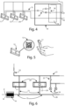
Figures 2 and 3 show two block diagrams of a possible configuration of emergency lighting equipment controlled remotely by the control apparatus according to the invention; -
Figure 4 shows an enlarged block diagram of one of the components ofFigure 3 ; -
Figure 5 shows a schematic view of an operating mode of the control apparatus according to the invention, integrating that shown inFigures 2 and 3 ; -
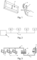
Figure 6 shows a schematic circuit diagram of another operating mode of the control apparatus according to the invention. - With reference to the accompanying drawings, the apparatus for remote control of emergency lighting equipment, according to the invention, is based on the use of the
flash 10 of a smartphone ortablet 11 as data transmission source and of one or more lighting appliances oremergency lamps 12. Theflash 10 of the smartphone ortablet 11 has minimum characteristics and, controlled by a specific software application (APP), allows the sending of coded signals according to the proprietary protocol of theemergency lamp 12, in such a way that the communication from the smartphone ortablet 11 to thelamp 12 occurs with ON/OFF cycles of theflash 10 of the smartphone ortablet 11, with an ON/OFF frequency of a few tens of Hz. The choice of this type of transmitter is dictated by the widespread use of smartphones and tablets, as well as the wish to simplify the work of the personnel responsible for installation and maintenance of theemergency lamps 12, avoiding the use of further devices such as centralised control units and/or remote control devices. - For the transmission phase use is made of a software application (APP) operating inside the smartphone or
tablet 11 which is able to send optical commands by modulating the switching ON and OFF of theflash 10 of the smartphone ortablet 11; the APP is designed to send coded luminous messages by means of theflash 10. - Basically, by using the dedicated APP, it is possible to interact directly with a single emergency lamp through a one-way optical communication; it is therefore possible to modify the configuration parameters of each single lamp, start the diagnostic tests and carry out other advanced functions. Each lighting appliance or
emergency lamp 12 can be used in the following configurations or operating mode: - "autotest", according to which the
emergency lamp 12 can operate in "stand alone" mode, carrying out the functions typical of an "autotest" emergency lamp (minimum configuration of use of the emergency lamp 12); by cutting a bridge it is possible to configure the autonomy of the emergency lamp; - "Cablecom® optical mode" operation, according to which the
lamp 12 is able to receive luminous commands of the actuation type or simply configuration commands, using the smartphone ortablet 11, during installation, that is, a predefined time window from the time in which the power supply is provided; - operation with "basic control unit", according to which a series of
emergency lamps 12, all mounted on a dedicated line, communicate on the power supply bus controlled directly upstream by a special local control unit controlled with just a few buttons, a multi-turn rotary switch, some selection LEDs and a LED for the result of the tests (system status); - operation with "advanced control unit", according to which a series of
emergency lamps 12, all mounted on a dedicated line, communicate on the power supply bus controlled directly upstream by a special WI-FI control unit; a dedicated APP allows the WI-FI connection to the control unit allowing the installer to control the system from a smartphone by means of an advanced interface. - According to the "Cablecom® optical mode", the
emergency lamp 12 can be controlled and configured using the luminous commands of the flash of the smartphone ortablet 11 by means of a special APP installed on the smartphone or tablet 11 (Fig. 1 ). - The optical communication, of the one-way type, is characterised by actuation type commands or simple configuration commands. The commands which can always be actuated on the
lamp 12 are "operational test start", "stop test" and "rest mode"; this basically a remote control of the test button of thelamp 12. - The other commands provided can, on the other hand, only be actuated following a synchronisation procedure of the mains AC power supply; more in detail, once the mains power supply is provided, it must be removed and restored in less than 3 seconds (that is, a mains power supply of less than 3 seconds must be generated) and from the time in which the synchronisation procedure is completed a time window of 2 hours is opened, within which the
lamp 12 can receive all the actuation and/or configuration commands provided by the APP. - This enables maximum safety of the system of emergency lamps to be achieved, since only the installer who has access to the control panel can remove or provide the power supply to the lamps and consequently enable the use of the optical commands.
- The
emergency lamp 12 will respond to the commands received by actuating the command (and, in this case, the user will have a visual check on the operation, since the lamp will switch ON or OFF) or generate an "acknowledge" flashing light (command received correctly) for the configuration commands received. - The optical commands relative to the "Cablecom® optical mode" implemented in the APP are as follows:
- operational test start and operational test stop (basic functions, which can always be actuated);
- hours of autonomy in emergency mode as a function of the luminous flow emitted (configuration command which can be actuated in the time window of 2 hours);
- setting SE, SA, PS functions, odd and even (configuration commands which can be actuated in the time window of 2 hours);
- start autonomy test, stop autonomy test, sync lamps and rest mode off with lamp in emergency mode (actuation commands which can be actuated in the time window of 2 hours);
- set test duration, set test duration equal to autonomy, factory reset (advanced functions which can be actuated in the time window of 2 hours).
- Each
emergency lamp 12 is identified by a unique number present inside the firmware of the apparatus and inside a QR-Code 13 shown on thelamp 12; this identification code is fundamental if theemergency lamp 12 is used in the operating mode with "basic control unit" or with "advanced control unit", as described below. - According to the operating mode with "basic control unit", the emergency lamps 12 (indicated with L1, L2,..., LN in
Figs. 2 and 3 ) are mounted on adedicated emergency line 18, upstream of which is installed acontrol unit 16; the requirement to wire the lamps on thededicated emergency line 18 is good and normal practice. - The emergency lamps L1, L2,..., LN continue to operate completely autonomously, according to the autotest mode described above, until the
control unit 16 is inserted upstream of the dedicatedpower supply line 18; in this configuration the lamps L1, L2,..., LN acquire the capacity to receive and send data (Fig. 2 ). - The dedicated
power supply line 18 can be fitted with a maximum of 32 lamps L1, L2,..., LN, but preferably the systems have approximately ten lamps. - The
control unit 16 is able to switch thepower supply line 18 onto acommunication bus 15 by simulating the lack ofmains power supply 14 and operating the lamps by battery; in this condition it is possible to set up a two-way and immediate communication between the individual lamps and thecontrol unit 16 and, in short, thepower supply bus 18 switched by thecontrol unit 16 becomes a low voltage communication bus 15 (Figs. 3 and4 ). - For this reason it is fundamental that the
power supply bus 18 is polarised; consequently, during wiring and/or installation it is necessary to comply with the correct polarity P, N. - Basically, the power supply line P, N enters into the
control unit 16 with the neutral N through and the phase P, alternatively, either through or switched on thelow voltage bus 18, in order to manage a power of approximately 3kW for powering the lamps in ordinary operation and providing 250 mA at 12V during data transmission. - In this way, the system is able to communicate with the lamps by means of the
bus 15 which uses the emergency electrical system for data transmission (basically, a "Power over Bus" (PoB) system is adopted applied to the emergency lighting sector, with high energy available on the bus and limited costs); in particular, thecontrol unit 16 is able to connect with the lamps switching the two power supply cables in thecommunication bus 15, so as to avoid any possibility of interference between the data transmission and the passage of current. - Once the lamps L1, L2,..., LN and the
control unit 16 are wired it is necessary to activate the system by means of a configuration phase during which thecontrol unit 16 searches for all the lamps present in the system. Thecontrol unit 16 can consist of two embodiments: "basic control unit" and "advanced control unit". - The
control unit 16, in the "basic control unit" version, is a module consisting of a 12 Volt power supply unit 19, arelay 20 which is able to switch the mains power supply bus (230Vac) on the communication bus (12V) and the communication and interfacing electronics consisting of buttons for actuating the various functions, configuration rotary switch and signalling LEDs (Fig. 4 ). - In the operating mode with "advanced control unit", the
control unit 16 expands the functionalities of the "basic control unit" described above with a WI-FI communication module; in that case, by using a smartphone or tablet and using a dedicated APP, it is possible to connect to the local WI-FI network generated by thecontrol unit 16 and thereby thecontrol unit 16 is able to show status information for the system with details of each individual lamp, as well as receive actuation and configuration commands both broadcast and oriented to the individual lamp. - All the lamps are fitted with a micro-switch which is able to carry out an operational diagnosis either autonomously or by receiving commands from the
communication bus 15 and to communicate the test results in local mode through a code of flashes and/or colours of special status LEDs; when thecontrol unit 16 switches the line P on thebus 15 it is able to communicate with the lamps, requesting the results of the tests or communicating set-up instructions, whilst when the lamps are connected to thecommunication bus 15 they can communicate to thecontrol unit 16 the result of the tests or the status of the parameters of each lamp. - In particular, as well as the configuration procedure, which will be described below, the "basic control unit" 16 allows operational tests to be performed (tests for switching ON the emergency lamp for 30 seconds), autonomy test (tests for switching ON the emergency lamp for a predetermined duration in autonomous mode), a stop of the tests being performed and a function for inhibition of the emergency in the case of switching OFF of the system (rest mode).
- The function selected (with relative green LED switched ON) is executed by pressing "OK" on the
control unit 16, whilst the outcome of the function started is shown on the status LED which switches ON red (with flashes of various durations) in the case of errors and green if there is no error. - The commands sent and the information collected by the
control unit 16 are oriented to the entire system; consequently, a red status LED will indicate that at least one of the lamps of the system has an error or fault and it will be the responsibility of the user to inspect the signalling LEDs of the individual lamps to identify the lamp with the fault. - In order to carry out the configuration procedure of the system, the
control unit 16 must know the number of lamps L1, L2,..., LN connected on the dedicated line before actuating any command; a preliminary configuration phase is therefore necessary in which to actuate the recognition of all the lamps. - In the case of a system with a "basic"
control unit 16 the installer, after wiring all the emergency lamps L1, L2,..., LN, selects the configuration function and, by means of the multi-turn rotary switch of thecontrol unit 16, defines the number of lamps present in the system, then selects the desired autonomy and selects the configuration phase by pressing "OK". - The LED of the
control unit 16 switches ON with the colour green if the number of lamps configured with the rotary selector coincides with the number of lamps which thecontrol unit 16 has detected. If this number does not coincide, thecontrol unit 16 sends an orange switching ON command of the signalling LED to all the lamps detected, in such a way that the lamps which remain with the steady green LED (or, possibly, steady red) can be considered as those not detected by thecontrol unit 16 and the installer can therefore resolve any fault. In practice, the signalling LED can be used as a guide for searching the number of lamps connected to thecontrol unit 16. As in the case of use of thecontrol unit 16 of the "basic" type, also in the case of use of thecontrol unit 16 of the "advanced" type, the control unit must know the number of lamps L1, L2,..., LN connected on thededicated line 18 before actuating any command. - In this case, the installer, once the dedicated APP has been downloaded and installed, will find two buttons: "remote control" and "Cablecom® connect control unit management".
- In the "remote control" mode, the installer can, anonymously (without registering), access the optical commands and can send the commands directly, in a one-way direction, as described above with regard to the "Cablecom® optical mode".
- In the "Cablecom® connect control unit management" mode, the
advanced control unit 16 automatically generates a WI-FI network (in Access Point mode), to which it is possible to connect by smartphone and specific APP. Once the connection has been executed, the user will have complete control of thecontrol unit 16 and will be able to send/receive commands and collect system data. The configurations and the commands can be performed both in broadcast mode and in individual mode (oriented to the individual lamp). The dedicated APP includes all the basic functions present on the user interface of the "basic" control unit, as well as the advanced functions for data collection and configuration of system and/or lamps. - The basic commands which are available and which can be actuated by the APP are those for configuration of the system, operational test start, autonomy test start, stop test, rest mode.
- Further commands/advanced configurations available by means of the dedicated APP regard the programming of automatic tests (with definition of the periodicity and the start date of the first test and with programming which can be actuated both for the operational tests and for the autonomy tests), status of the system (summary of the data of the emergency lamps configured in the control unit, association of a test to each lamp present in the list to have a position reference of the lamp or a description which can be easily interpreted, configuration for each individual lamp present with specific parameters oriented to the individual lamp), a regular logbook of the results of the automatic tests (the user is able to download a pdf document generated following a certain periodic autonomy test or periodic operational test; the report can be saved and if necessary shared or sent via mail and contains the date and time of the data of the automatic test, type of automatic test performed, identification number and/or descriptive text of the individual lamp, fault found and/or test result).
- Basically, by using the Wi-Fi technology of the
control unit 16, it is possible to configure the entire system, start operational tests and autonomy tests, modify the parameters of each lamp and enable advanced functionalities. The above-mentioned advanced functionalities include the one illustrated in detail in the appendedFigure 6 ; the system layout shown highlights the simplicity of the function. Basically, considering that thepower supply cable 21 of the ordinary lighting, the system of which comprises aprotection device 22 and acontrol device 23 oflamps 24 for the ordinary lighting, is the same on which thecontrol unit 16 transmits the data for the control of the emergency lamps L1, L2,... LN, it is possible, by usingrespective input connectors 25 wired between thecable 21 and the lamps L1, L2... LN, to activate the normal emergency operation of the lamps L1, L2... LN even in the case of a local power failure of a section of the ordinary lighting system. Upon completion of the nominal autonomy of each lamp L1, L2... LN, thebus 15 supplies the energy necessary to keep the lamp L1, L2... LN switched ON with practically infinite autonomy (possibly with a reduced luminous flow) providing there is power supply on theemergency supply line 26. - Therefore, by enabling this function, the PoB ("Power over Bus") technology allows, in the case of a local emergency, the emergency lamps L1, L2... LN (recovery function) to continue to be powered even if the local lighting line is interrupted; in this way possible to obtain an extension of autonomy with nominal luminous flow and a standby reduced luminous flow, which activated automatically when the battery of the lamp L1, L2... LN is flat (or broken), in order to anyway guarantee a useful service (for example, in the case of exits from premises due to night-time faults and/or on construction sites, etc.).
- The technical features of the apparatus and the relative method for the remote control of emergency lighting equipment, according to the invention, clearly emerge from the description, as do the advantages thereof.
- In particular, as well as the advantages mentioned above, the following should be noted:
- simplified two-wire wiring;
- possibility of use of the system on standard emergency lamps, without having to intervene on the electrical system;
- communication reliability without interference problems even with communication distances greater than 250 metres and also indoors;
- possibility of continuing to power the emergency lamp even in the case of a power failure of the local lighting line, with extension of the autonomy of the lamp with a nominal luminous flow and continuous activation of a reduced luminous flow (with flat of broken battery);
- possibility of transforming the SE lamps into SA, if necessary with a reduced flow, in order to archive a night-time lighting;
- no generation of electrosmog.
Claims (8)
- System for remote control of emergency lighting equipment (12, L1, L2, ..., LN), the system being configured to be coupled to a mains power supply (14), the system comprising said emergency lighting equipment (12, L1, L2, ..., LN) and a smartphone or tablet (11) comprising at least one flash configured to send optical commands in the form of coded luminous messages and a control system configured to be managed by a software application or APP running in the smartphone or tablet (11) and configured to modulate switching on and off of said at least one flash of the smartphone or tablet (11), said emergency lighting equipment (12, L1, L2, ..., LN) comprising a series of emergency lamps (12, L1, L2, ..., LN) and a central unit (16), wherein each emergency lamp of said series of emergency lamps (12, L1, L2, ..., LN) is configured to receive said optical commands from said smartphone or tablet (11) for performing functional tests or remote configurations, both during installation of each emergency lamp (12, L1, L2, ..., LN) and for a fixed period of time starting from the mains power supply (14) being restored to each emergency lamp (12, L1, L2, ...,LN) after being removed for a prefixed period of time,characterized in that:the central unit (16) is configured to be coupled to the mains power supply (14) through a polarized supply line (P, N), wherein said series of emergency lamps (12, L1, L2, ..., LN) are configured to be mounted on the polarized supply line (P, N), the polarized supply line (P, N) configured to be managed upstream by said central unit (16), said central unit (16) being further configured to manage data received from said series of emergency lamps (12, L1, L2, ..., LN), said central unit (16) being further configured to switch said polarized supply line (P, N) into a communication bus (15), said communication bus (15) being configured to supply said series of emergency lamps (12, L1, L2, ... LN) and to transmit data to said series of emergency lamps (12, L1, L2, ... LN), said central unit (16) comprising a low voltage power supply (19) and an electronic communication circuit which includes a series of LEDs which are configured to signal a correct operation and/or errors, wherein each emergency lamp (12, L1, L2, ... LN) comprises a micro-switch configured to receive commands from said communication bus (15) and to transmit signals of the correct operation and/or errors through said signaling LEDs.
- System as claimed in claim 1, wherein said low voltage power supply (19) is configured to provide a low voltage bus (18), wherein said central unit (16) further comprises a relay (20) configured to switch said polarized supply line (P, N) into the low voltage bus (18), to thereby provide the communication bus (15).
- System according to at least one of the previous claims,
wherein said smartphone or tablet (11) is configured to send, through said software application of APP, said optical commands to said series of emergency lamps (12, L1, L2, ..., LN), through said central unit (16), so as to perform functional tests, autonomy tests, synchronization tests, tests related to hours of emergency autonomy of said series of emergency lamps (12, L1, L2, ..., LN). - System as claimed in at least one of the previous claims,
wherein each emergency lamp (12, L1, L2, ..., LN) and/or said central unit (16) is/are configured to be identified by a unique number of a OR-Code (13). - System as claimed in at least one of the previous claims,
wherein each emergency lamp (12, L1, L2, ... LN) is configured to receive said optical commands via said software application or APP running in said smartphone or tablet (11). - System as claimed in at least one of the previous claims,
wherein said central unit (16) further comprises a WI-FI communication module, wherein said central unit (16) is configured to generate a local WI-FI network, and wherein said smartphone or tablet (11) is configured to connect to said local WI-FI network using said software application or APP running in said smartphone or tablet (11), so that said central unit (16) is configured to show a status information of said emergency lighting equipment (12, L1, L2, ..., LN) and of each emergency lamp (12, L1, L2..., LN), as well as to receive actuation and configuration commands addressed to said emergency lighting equipment (12, L1, L2, ..., LN) and/or to each emergency lamp (12, L1, L2, ..., LN). - System as claimed in claim 6, wherein said central unit (16) is configured to send and receive the actuation and/or configuration commands and to collect the data relating to each emergency lamp (12, L1, L2..., LN) and/or data relating to said emergency lighting equipment (12, L1, L2, ..., LN), said commands including periodic automatic test programs, plant status checks and periodic collections of test results.
- System as claimed in at least one of the previous claims, wherein the system is configured to be further coupled to an ordinary lighting system comprising lamps (24) for ordinary lighting, wherein the system further comprises input connectors (25) and a cable (21) for supplying power to the lamps (24) for ordinary lighting, said input connectors (25) being provided between said cable (21) for supplying power to the lamps (24) for ordinary lighting and each emergency lamp (12, L1, L2... LN) in order to activate an emergency function of said series of emergency lamps (12, L1, L2..., LN) in case of a blackout of a section of the ordinary lighting system, said communication bus (15) being configured to supply energy for supplying at least one of said series of emergency lamps (12, L1, L2..., LN) with a nominal luminous flux for a first period of time and with a reduced luminous flux configured to be activated at the end of said first period of time.
Applications Claiming Priority (2)
| Application Number | Priority Date | Filing Date | Title |
|---|---|---|---|
| IT201900004351 | 2019-03-26 | ||
| PCT/IT2020/050060 WO2020194355A1 (en) | 2019-03-26 | 2020-03-12 | Apparatus and method for a remote control of emergency lighting equipment |
Publications (3)
| Publication Number | Publication Date |
|---|---|
| EP3949688A1 EP3949688A1 (en) | 2022-02-09 |
| EP3949688B1 true EP3949688B1 (en) | 2023-12-13 |
| EP3949688C0 EP3949688C0 (en) | 2023-12-13 |
Family
ID=67002243
Family Applications (1)
| Application Number | Title | Priority Date | Filing Date |
|---|---|---|---|
| EP20714708.3A Active EP3949688B1 (en) | 2019-03-26 | 2020-03-12 | System for remote control of emergency lighting equipment |
Country Status (4)
| Country | Link |
|---|---|
| US (1) | US20220159816A1 (en) |
| EP (1) | EP3949688B1 (en) |
| CN (1) | CN113678573A (en) |
| WO (1) | WO2020194355A1 (en) |
Families Citing this family (2)
| Publication number | Priority date | Publication date | Assignee | Title |
|---|---|---|---|---|
| JP2024508982A (en) | 2021-03-09 | 2024-02-28 | シグニファイ ホールディング ビー ヴィ | Auxiliary configuration for LED tube lamps |
| EP4064797B1 (en) * | 2021-03-26 | 2023-12-27 | Tridonic GmbH & Co KG | Communication gateway module |
Family Cites Families (7)
| Publication number | Priority date | Publication date | Assignee | Title |
|---|---|---|---|---|
| ITVI20040286A1 (en) * | 2004-12-10 | 2005-03-10 | Beghelli Spa | EMERGENCY LIGHTING SYSTEM WITH CENTRALIZED DIAGNOSIS |
| US7321302B2 (en) * | 2004-12-10 | 2008-01-22 | Beghelli S.P.A | Central test radio frequency system for emergency lighting |
| CN103974498A (en) * | 2013-02-05 | 2014-08-06 | 暐诗康科技有限公司 | Cellular emergency lighting management system |
| WO2015135033A1 (en) * | 2014-03-13 | 2015-09-17 | Kortek Industries Pty Ltd | Wireless and power line light pairing dimming and control |
| US11582058B2 (en) * | 2014-12-01 | 2023-02-14 | Signify Holding B.V. | Identifying and controlling signal influence on one or more properties of emitted light |
| EP3342258B1 (en) * | 2015-12-01 | 2019-06-05 | Signify Holding B.V. | Coded light modulation arrangement |
| CN108702832B (en) * | 2016-02-08 | 2021-01-01 | 百家丽有限公司 | Apparatus and method for remotely controlling lighting devices |
-
2020
- 2020-03-12 WO PCT/IT2020/050060 patent/WO2020194355A1/en unknown
- 2020-03-12 US US17/593,818 patent/US20220159816A1/en not_active Abandoned
- 2020-03-12 EP EP20714708.3A patent/EP3949688B1/en active Active
- 2020-03-12 CN CN202080024579.9A patent/CN113678573A/en active Pending
Also Published As
| Publication number | Publication date |
|---|---|
| WO2020194355A1 (en) | 2020-10-01 |
| US20220159816A1 (en) | 2022-05-19 |
| CN113678573A (en) | 2021-11-19 |
| EP3949688C0 (en) | 2023-12-13 |
| EP3949688A1 (en) | 2022-02-09 |
Similar Documents
| Publication | Publication Date | Title |
|---|---|---|
| EP3949688B1 (en) | System for remote control of emergency lighting equipment | |
| US4945280A (en) | Independent emergency lighting system with self-diagnosis | |
| CN102365598B (en) | emergency test control panel device, system and method | |
| KR101444242B1 (en) | Monitoring system for control device in a remote place having the self diagnosis function and method therefor | |
| US20130138757A1 (en) | Component addition/substitution method in a home automation wireless system | |
| JPS62268646A (en) | Controller to printer | |
| GB2319373A (en) | Allocating addresses to addressable devices | |
| JPH02181599A (en) | Building controller | |
| CN109302781A (en) | Emergency lighting system and correlation technique | |
| CN104349560A (en) | Fault detection apparatus for street lamp illumination system, and operation method thereof | |
| US20070228223A1 (en) | Device for activation and monitoring of a light-signal system for railway traffic | |
| CN103207592B (en) | The program control rim brake device of medical x-ray machine, programmed control method and special-purpose member | |
| US5459450A (en) | Presence-detecting system | |
| CN105786065B (en) | A kind of sewing device master control system | |
| EP1943708B1 (en) | Emergency light system and luminaire module | |
| CN215340817U (en) | Numerical control machine tool control system | |
| EP3334253B1 (en) | Remote control method for lighting fixtures | |
| CN210297351U (en) | Debugging device for automatic master station and distribution network terminal of distribution network | |
| KR101672368B1 (en) | Power management system using triplex mode function providing smart concent and smart concent, power management system using triplex mode function providing smart multi-tap and multi-tap | |
| KR101531665B1 (en) | Power management system using triplex mode function providing Smart switch and triplex mode function providing Smart switch | |
| EP2575114B1 (en) | An alarm controller | |
| EP0576098A2 (en) | System of transmission of information about the state of loads connected to an electric line | |
| CN113472081B (en) | Protective device clamp plate on-line monitoring and warning device | |
| CN101187681B (en) | Signalling device, and control method, for automatisms | |
| KR102296372B1 (en) | Emergency guide apparatus and operating method thereof |
Legal Events
| Date | Code | Title | Description |
|---|---|---|---|
| STAA | Information on the status of an ep patent application or granted ep patent |
Free format text: STATUS: UNKNOWN |
|
| STAA | Information on the status of an ep patent application or granted ep patent |
Free format text: STATUS: THE INTERNATIONAL PUBLICATION HAS BEEN MADE |
|
| PUAI | Public reference made under article 153(3) epc to a published international application that has entered the european phase |
Free format text: ORIGINAL CODE: 0009012 |
|
| STAA | Information on the status of an ep patent application or granted ep patent |
Free format text: STATUS: REQUEST FOR EXAMINATION WAS MADE |
|
| 17P | Request for examination filed |
Effective date: 20210708 |
|
| AK | Designated contracting states |
Kind code of ref document: A1 Designated state(s): AL AT BE BG CH CY CZ DE DK EE ES FI FR GB GR HR HU IE IS IT LI LT LU LV MC MK MT NL NO PL PT RO RS SE SI SK SM TR |
|
| DAV | Request for validation of the european patent (deleted) | ||
| DAX | Request for extension of the european patent (deleted) | ||
| P01 | Opt-out of the competence of the unified patent court (upc) registered |
Effective date: 20230512 |
|
| GRAP | Despatch of communication of intention to grant a patent |
Free format text: ORIGINAL CODE: EPIDOSNIGR1 |
|
| STAA | Information on the status of an ep patent application or granted ep patent |
Free format text: STATUS: GRANT OF PATENT IS INTENDED |
|
| INTG | Intention to grant announced |
Effective date: 20230814 |
|
| GRAS | Grant fee paid |
Free format text: ORIGINAL CODE: EPIDOSNIGR3 |
|
| GRAA | (expected) grant |
Free format text: ORIGINAL CODE: 0009210 |
|
| STAA | Information on the status of an ep patent application or granted ep patent |
Free format text: STATUS: THE PATENT HAS BEEN GRANTED |
|
| AK | Designated contracting states |
Kind code of ref document: B1 Designated state(s): AL AT BE BG CH CY CZ DE DK EE ES FI FR GB GR HR HU IE IS IT LI LT LU LV MC MK MT NL NO PL PT RO RS SE SI SK SM TR |
|
| REG | Reference to a national code |
Ref country code: GB Ref legal event code: FG4D |
|
| REG | Reference to a national code |
Ref country code: CH Ref legal event code: EP |
|
| REG | Reference to a national code |
Ref country code: DE Ref legal event code: R096 Ref document number: 602020022668 Country of ref document: DE |
|
| REG | Reference to a national code |
Ref country code: IE Ref legal event code: FG4D |
|
| U01 | Request for unitary effect filed |
Effective date: 20231220 |
|
| U07 | Unitary effect registered |
Designated state(s): AT BE BG DE DK EE FI FR IT LT LU LV MT NL PT SE SI Effective date: 20240103 |
|
| P04 | Withdrawal of opt-out of the competence of the unified patent court (upc) registered |
Effective date: 20231222 |
|
| PG25 | Lapsed in a contracting state [announced via postgrant information from national office to epo] |
Ref country code: GR Free format text: LAPSE BECAUSE OF FAILURE TO SUBMIT A TRANSLATION OF THE DESCRIPTION OR TO PAY THE FEE WITHIN THE PRESCRIBED TIME-LIMIT Effective date: 20240314 |