EP3945933B1 - Körperpflegevorrichtung zur hautbehandlung und verfahren zur herstellung - Google Patents
Körperpflegevorrichtung zur hautbehandlung und verfahren zur herstellung Download PDFInfo
- Publication number
- EP3945933B1 EP3945933B1 EP20722754.7A EP20722754A EP3945933B1 EP 3945933 B1 EP3945933 B1 EP 3945933B1 EP 20722754 A EP20722754 A EP 20722754A EP 3945933 B1 EP3945933 B1 EP 3945933B1
- Authority
- EP
- European Patent Office
- Prior art keywords
- personal care
- care device
- skin treatment
- light emitting
- treatment personal
- Prior art date
- Legal status (The legal status is an assumption and is not a legal conclusion. Google has not performed a legal analysis and makes no representation as to the accuracy of the status listed.)
- Active
Links
Images


Classifications
-
- A—HUMAN NECESSITIES
- A45—HAND OR TRAVELLING ARTICLES
- A45D—HAIRDRESSING OR SHAVING EQUIPMENT; EQUIPMENT FOR COSMETICS OR COSMETIC TREATMENTS, e.g. FOR MANICURING OR PEDICURING
- A45D44/00—Other cosmetic or toiletry articles, e.g. for hairdressers' rooms
-
- A—HUMAN NECESSITIES
- A61—MEDICAL OR VETERINARY SCIENCE; HYGIENE
- A61N—ELECTROTHERAPY; MAGNETOTHERAPY; RADIATION THERAPY; ULTRASOUND THERAPY
- A61N5/00—Radiation therapy
- A61N5/06—Radiation therapy using light
- A61N5/0613—Apparatus adapted for a specific treatment
- A61N5/0616—Skin treatment other than tanning
-
- A—HUMAN NECESSITIES
- A61—MEDICAL OR VETERINARY SCIENCE; HYGIENE
- A61N—ELECTROTHERAPY; MAGNETOTHERAPY; RADIATION THERAPY; ULTRASOUND THERAPY
- A61N5/00—Radiation therapy
- A61N5/06—Radiation therapy using light
- A61N5/0613—Apparatus adapted for a specific treatment
- A61N5/0624—Apparatus adapted for a specific treatment for eliminating microbes, germs, bacteria on or in the body
-
- B—PERFORMING OPERATIONS; TRANSPORTING
- B26—HAND CUTTING TOOLS; CUTTING; SEVERING
- B26B—HAND-HELD CUTTING TOOLS NOT OTHERWISE PROVIDED FOR
- B26B19/00—Clippers or shavers operating with a plurality of cutting edges, e.g. hair clippers, dry shavers
- B26B19/38—Details of, or accessories for, hair clippers, or dry shavers, e.g. housings, casings, grips, guards
- B26B19/46—Details of, or accessories for, hair clippers, or dry shavers, e.g. housings, casings, grips, guards providing for illuminating the area to be shaved or clipped
-
- B—PERFORMING OPERATIONS; TRANSPORTING
- B26—HAND CUTTING TOOLS; CUTTING; SEVERING
- B26B—HAND-HELD CUTTING TOOLS NOT OTHERWISE PROVIDED FOR
- B26B21/00—Razors of the open or knife type; Safety razors or other shaving implements of the planing type; Hair-trimming devices involving a razor-blade; Equipment therefor
- B26B21/40—Details or accessories
- B26B21/4012—Housing details, e.g. for cartridges
-
- B—PERFORMING OPERATIONS; TRANSPORTING
- B26—HAND CUTTING TOOLS; CUTTING; SEVERING
- B26B—HAND-HELD CUTTING TOOLS NOT OTHERWISE PROVIDED FOR
- B26B21/00—Razors of the open or knife type; Safety razors or other shaving implements of the planing type; Hair-trimming devices involving a razor-blade; Equipment therefor
- B26B21/40—Details or accessories
- B26B21/405—Electric features; Charging; Computing devices
- B26B21/4056—Sensors or controlling means
-
- B—PERFORMING OPERATIONS; TRANSPORTING
- B26—HAND CUTTING TOOLS; CUTTING; SEVERING
- B26B—HAND-HELD CUTTING TOOLS NOT OTHERWISE PROVIDED FOR
- B26B21/00—Razors of the open or knife type; Safety razors or other shaving implements of the planing type; Hair-trimming devices involving a razor-blade; Equipment therefor
- B26B21/40—Details or accessories
- B26B21/46—Details or accessories for illuminating the skin
-
- B—PERFORMING OPERATIONS; TRANSPORTING
- B26—HAND CUTTING TOOLS; CUTTING; SEVERING
- B26B—HAND-HELD CUTTING TOOLS NOT OTHERWISE PROVIDED FOR
- B26B21/00—Razors of the open or knife type; Safety razors or other shaving implements of the planing type; Hair-trimming devices involving a razor-blade; Equipment therefor
- B26B21/40—Details or accessories
- B26B21/48—Heating means
-
- B—PERFORMING OPERATIONS; TRANSPORTING
- B26—HAND CUTTING TOOLS; CUTTING; SEVERING
- B26B—HAND-HELD CUTTING TOOLS NOT OTHERWISE PROVIDED FOR
- B26B21/00—Razors of the open or knife type; Safety razors or other shaving implements of the planing type; Hair-trimming devices involving a razor-blade; Equipment therefor
- B26B21/40—Details or accessories
- B26B21/52—Handles, e.g. tiltable, flexible
- B26B21/526—Electric features
-
- H—ELECTRICITY
- H05—ELECTRIC TECHNIQUES NOT OTHERWISE PROVIDED FOR
- H05K—PRINTED CIRCUITS; CASINGS OR CONSTRUCTIONAL DETAILS OF ELECTRIC APPARATUS; MANUFACTURE OF ASSEMBLAGES OF ELECTRICAL COMPONENTS
- H05K1/00—Printed circuits
- H05K1/18—Printed circuits structurally associated with non-printed electric components
- H05K1/181—Printed circuits structurally associated with non-printed electric components associated with surface mounted components
-
- H—ELECTRICITY
- H05—ELECTRIC TECHNIQUES NOT OTHERWISE PROVIDED FOR
- H05K—PRINTED CIRCUITS; CASINGS OR CONSTRUCTIONAL DETAILS OF ELECTRIC APPARATUS; MANUFACTURE OF ASSEMBLAGES OF ELECTRICAL COMPONENTS
- H05K3/00—Apparatus or processes for manufacturing printed circuits
- H05K3/30—Assembling printed circuits with electric components, e.g. with resistor
- H05K3/303—Surface mounted components, e.g. affixing before soldering, aligning means, spacing means
-
- H—ELECTRICITY
- H05—ELECTRIC TECHNIQUES NOT OTHERWISE PROVIDED FOR
- H05K—PRINTED CIRCUITS; CASINGS OR CONSTRUCTIONAL DETAILS OF ELECTRIC APPARATUS; MANUFACTURE OF ASSEMBLAGES OF ELECTRICAL COMPONENTS
- H05K7/00—Constructional details common to different types of electric apparatus
- H05K7/20—Modifications to facilitate cooling, ventilating, or heating
- H05K7/2039—Modifications to facilitate cooling, ventilating, or heating characterised by the heat transfer by conduction from the heat generating element to a dissipating body
-
- A—HUMAN NECESSITIES
- A45—HAND OR TRAVELLING ARTICLES
- A45D—HAIRDRESSING OR SHAVING EQUIPMENT; EQUIPMENT FOR COSMETICS OR COSMETIC TREATMENTS, e.g. FOR MANICURING OR PEDICURING
- A45D2200/00—Details not otherwise provided for in A45D
- A45D2200/20—Additional enhancing means
- A45D2200/205—Radiation, e.g. UV, infrared
-
- A—HUMAN NECESSITIES
- A61—MEDICAL OR VETERINARY SCIENCE; HYGIENE
- A61N—ELECTROTHERAPY; MAGNETOTHERAPY; RADIATION THERAPY; ULTRASOUND THERAPY
- A61N5/00—Radiation therapy
- A61N5/06—Radiation therapy using light
- A61N2005/0626—Monitoring, verifying, controlling systems and methods
-
- A—HUMAN NECESSITIES
- A61—MEDICAL OR VETERINARY SCIENCE; HYGIENE
- A61N—ELECTROTHERAPY; MAGNETOTHERAPY; RADIATION THERAPY; ULTRASOUND THERAPY
- A61N5/00—Radiation therapy
- A61N5/06—Radiation therapy using light
- A61N2005/0635—Radiation therapy using light characterised by the body area to be irradiated
- A61N2005/0643—Applicators, probes irradiating specific body areas in close proximity
- A61N2005/0644—Handheld applicators
-
- A—HUMAN NECESSITIES
- A61—MEDICAL OR VETERINARY SCIENCE; HYGIENE
- A61N—ELECTROTHERAPY; MAGNETOTHERAPY; RADIATION THERAPY; ULTRASOUND THERAPY
- A61N5/00—Radiation therapy
- A61N5/06—Radiation therapy using light
- A61N2005/065—Light sources therefor
- A61N2005/0651—Diodes
-
- A—HUMAN NECESSITIES
- A61—MEDICAL OR VETERINARY SCIENCE; HYGIENE
- A61N—ELECTROTHERAPY; MAGNETOTHERAPY; RADIATION THERAPY; ULTRASOUND THERAPY
- A61N5/00—Radiation therapy
- A61N5/06—Radiation therapy using light
- A61N2005/065—Light sources therefor
- A61N2005/0651—Diodes
- A61N2005/0652—Arrays of diodes
-
- A—HUMAN NECESSITIES
- A61—MEDICAL OR VETERINARY SCIENCE; HYGIENE
- A61N—ELECTROTHERAPY; MAGNETOTHERAPY; RADIATION THERAPY; ULTRASOUND THERAPY
- A61N5/00—Radiation therapy
- A61N5/06—Radiation therapy using light
- A61N2005/0658—Radiation therapy using light characterised by the wavelength of light used
- A61N2005/0662—Visible light
-
- A—HUMAN NECESSITIES
- A61—MEDICAL OR VETERINARY SCIENCE; HYGIENE
- A61N—ELECTROTHERAPY; MAGNETOTHERAPY; RADIATION THERAPY; ULTRASOUND THERAPY
- A61N5/00—Radiation therapy
- A61N5/06—Radiation therapy using light
- A61N2005/0664—Details
- A61N2005/0668—Apparatus adapted for operation in a moist environment, e.g. bath or shower
-
- H—ELECTRICITY
- H05—ELECTRIC TECHNIQUES NOT OTHERWISE PROVIDED FOR
- H05K—PRINTED CIRCUITS; CASINGS OR CONSTRUCTIONAL DETAILS OF ELECTRIC APPARATUS; MANUFACTURE OF ASSEMBLAGES OF ELECTRICAL COMPONENTS
- H05K2201/00—Indexing scheme relating to printed circuits covered by H05K1/00
- H05K2201/10—Details of components or other objects attached to or integrated in a printed circuit board
- H05K2201/10007—Types of components
- H05K2201/10106—Light emitting diode [LED]
-
- H—ELECTRICITY
- H05—ELECTRIC TECHNIQUES NOT OTHERWISE PROVIDED FOR
- H05K—PRINTED CIRCUITS; CASINGS OR CONSTRUCTIONAL DETAILS OF ELECTRIC APPARATUS; MANUFACTURE OF ASSEMBLAGES OF ELECTRICAL COMPONENTS
- H05K2201/00—Indexing scheme relating to printed circuits covered by H05K1/00
- H05K2201/10—Details of components or other objects attached to or integrated in a printed circuit board
- H05K2201/10007—Types of components
- H05K2201/10151—Sensor
-
- H—ELECTRICITY
- H05—ELECTRIC TECHNIQUES NOT OTHERWISE PROVIDED FOR
- H05K—PRINTED CIRCUITS; CASINGS OR CONSTRUCTIONAL DETAILS OF ELECTRIC APPARATUS; MANUFACTURE OF ASSEMBLAGES OF ELECTRICAL COMPONENTS
- H05K2201/00—Indexing scheme relating to printed circuits covered by H05K1/00
- H05K2201/10—Details of components or other objects attached to or integrated in a printed circuit board
- H05K2201/10431—Details of mounted components
- H05K2201/10507—Involving several components
- H05K2201/10522—Adjacent components
Definitions
- the present invention relates to a skin treatment personal care device.
- Blue light in the approximate range of 400-500 nanometer (nm) wavelength spectrum has been effective in treating acne and can be microbicidal.
- Positively Clear Acne Clearing Blue Light by TRIA BEAUTY ® Visible and near infra-red red light in the approximate range of 600-900 nm wavelength spectrum has proved helpful in wound care and the reduction of wrinkles and age spots.
- An important aspect of these light energy devices is that the power output is less than that of devices used for hair removal, for example, U.S. Patent number 5,735,844 to Anderson et al being representative of disclosing light energy devices for hair removal and hair growth inhibition.
- Shaving razors have been proposed that incorporate a light energy source that provides a beneficial effect to the skin of the user in a shaving razor.
- the size of the shaving razor cartridge is relatively small. Accordingly, the light energy source may generate heat that the shaving razor cartridge is unable to dissipate and/or control in a safe and efficient manner.
- the light energy source may be harmful if it is inadvertently exposed to the eyes.
- the application of light energy during a shaving stroke creates other issues, such as higher power LED may be used to compensate for the relatively small footprint of the razor as well as short contact time (e.g., time during a single shaving stroke). Accordingly, there is a need to provide a shaving razor capable of delivering safe and reliable light energy without burning the skin.
- JP 2001 029124 discusses a laser depilation probe that may have a safety razor attached to a tip of the probe.
- the invention provides a skin treatment personal care device according to the claims.
- the invention features, according to claim 1, a skin treatment personal care with a handle having a gripping portion at one end and a head portion at an opposing end.
- the head portion includes a heat dissipating housing having a top surface and defines a pocket.
- the heat dissipating housing is made of a material having a thermal diffusivity greater than 10 W / m K.
- a light emitting diode adapted to provide one or more skin benefits is positioned within in the pocket.
- a window forms a water tight seal covering the LED.
- the skin treatment personal care device further comprises a shaving razor cartridge mounted to the heat dissipating housing.
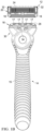
- FIGS. 1A and 1B one possible embodiment of the present disclosure is shown illustrating a skin treatment personal care device 10, such as a shaving razor.
- the skin treatment personal care device 10 includes a shaving razor cartridge 12 mounted to a handle 14, as shown in FIG. 1A .
- other treatment heads may alternatively be mounted to the handle 14, such as, a toothbrush or an applicator.
- the shaving razor cartridge 12 may be fixedly or pivotably mounted to the handle 14.
- the handle 14 includes a gripping portion 15 that holds a power source, such as one or more batteries (not shown) that supply power to a light bar assembly 16.
- the light bar assembly 16 may comprise one or more light emitting diodes (LEDS) 17.
- LEDS light emitting diodes
- the LED (or LEDs) are positioned to face the skin of the user when the light bar assembly 16 is mounted to the shaving razor cartridge 12 and the user takes a shaving stroke.
- the light bar assembly 16 may extend into one or more openings 18 ( FIG 1B ) defined by a housing 20 of the shaving razor cartridge 12.
- the light energy emitted by the LED has at least one wavelength in the range 400-1000 nm. At least one wavelength in the range 400-700 nm has also been found to be beneficial.
- Each LED may have a power consumption more than 100 mW, more preferably more than 200 mW, and a radiant power more than 100 mW, more preferably more than 200 mW.
- the light energy emitted by the LED provides at least one of acne treatment; bactericidal effects; repair of photodamage; anti-aging effects; reduction of scarring and wound healing, including healing wounds or other skin damage caused by shaving.
- the shaving razor cartridge 12 may be permanently attached or removably mounted from the handle 14, thus allowing the shaving razor cartridge 12 to be replaced.
- FIG. 1B illustrates the shaving razor cartridge 12 removed from the handle 14.
- the housing 20 of the shaving razor cartridge 12 may have include a guard 22, a cap 24 and one or more blades 26 mounted to the housing 20 between the cap 24 and the guard 22.
- the guard 22 may be toward a front portion of the housing 20 and the cap 24 may be toward a rear portion of the housing 20 (i.e., the guard 22 is in front of the blades 26 and the cap 24 is behind the blades 26).
- the guard 22 and the cap 24 may define a shaving plane that is tangent to the guard 22 and the cap 24.
- the guard 22 may be a solid or segmented bar that extends generally parallel to the blades 26.
- the light bar assembly 16 may be positioned in front of the guard 22. However, it is understood the light bar assembly may be positioned anywhere on the housing 20 (e.g., at the rear of the housing 20, near the cap 20).
- the light bar assembly 16 may comprise an outer surface 28 that contacts a consumer's skin during a shaving stroke.
- the light bar assembly 16 may be mounted to a head portion 30 of the handle 14.
- the light emitting diodes 17 may be recessed within the light bar assembly 16 (e.g., spaced apart from the outer surface 28).
- the blades 26 may be mounted to the housing 20 and secured by one or more clips 32.
- Other assembly methods known to those skilled in the art may also be used to secure and/or mount the blades 26 to the housing 20 including, but not limited to, wire wrapping, cold forming, hot staking, insert molding, ultrasonic welding, and adhesives.
- the clips 32 may comprise a metal, such as aluminum for conducting heat and acting as a sacrificial anode to help prevent corrosion of the blades 26. Although five blades 26 are shown, the housing 20 may have more or fewer blades 26 depending on the desired performance and cost of the shaving razor cartridge 12.
- the light bar assembly 16 may be positioned in front of the guard 22 and/or the skin engaging member 26.
- the light bar assembly 16 may be mounted to the housing 20 and in communication with the power source (not shown) via a printed circuit board (PCB) 34.
- the printed circuit board (PCB) 34 may be flexible to facilitate movement of the shaving razor cartridge 12.
- the light emitting diodes 17 may be mounted to the printed circuit board 34 and operatively coupled to the power source.
- the cap 24 may be a separate molded (e.g., a shaving aid filled reservoir) or extruded component (e.g., an extruded lubrication strip) that is mounted to the housing 20.
- the cap 24 may be a plastic or metal bar to support the skin and define the shaving plane.
- the cap 24 may be molded or extruded from the same material as the housing 20 or may be molded or extruded from a more lubricious shaving aid composite that has one or more water-leachable shaving aid materials to provide increased comfort during shaving.
- the shaving aid composite may comprise a water-insoluble polymer and a skin-lubricating water-soluble polymer.
- Suitable water-insoluble polymers which may be used include, but are not limited to, polyethylene, polypropylene, polystyrene, butadiene-styrene copolymer (e.g., medium and high impact polystyrene), polyacetal, acrylonitrile-butadiene-styrene copolymer, ethylene vinyl acetate copolymer and blends such as polypropylene/polystyrene blend, may have a high impact polystyrene (i.e., Polystyrene-butadiene), such as Mobil 4324 (Mobil Corporation).
- polystyrene i.e., Polystyrene-butadiene
- Mobil 4324 Mobil Corporation
- Suitable skin lubricating water-soluble polymers may include polyethylene oxide, polyvinyl pyrrolidone, polyacrylamide, hydroxypropyl cellulose, polyvinyl imidazoline, and polyhydroxyethylmethacrylate.
- Other water-soluble polymers may include the polyethylene oxides generally known as POLYOX (available from Union Carbide Corporation) or ALKOX (available from Meisei Chemical Works, Kyota, Japan). These polyethylene oxides may have molecular weights of about 100,000 to 6 million, for example, about 300,000 to 5 million.
- the polyethylene oxide may comprise a blend of about 40 to 80% of polyethylene oxide having an average molecular weight of about 5 million (e.g., POLYOX COAGULANT) and about 60 to 20% of polyethylene oxide having an average molecular weight of about 300,000 (e.g., POLYOX WSR-N-750).
- the polyethylene oxide blend may also contain up to about 10% by weight of a low molecular weight (i.e., MW ⁇ 10,000) polyethylene glycol such as PEG-100.
- the shaving aid composite may also optionally include an inclusion complex of a skin-soothing agent with a cylcodextrin, low molecular weight water-soluble release enhancing agents such as polyethylene glycol (e.g., 1-10% by weight), water-swellable release enhancing agents such as cross-linked polyacrylics (e.g., 2-7% by weight), colorants, antioxidants, preservatives, microbicidal agents, beard softeners, astringents, depilatories, medicinal agents, conditioning agents, moisturizers, cooling agents, etc.
- a skin-soothing agent with a cylcodextrin low molecular weight water-soluble release enhancing agents such as polyethylene glycol (e.g., 1-10% by weight), water-swellable release enhancing agents such as cross-linked polyacrylics (e.g., 2-7% by weight), colorants, antioxidants, preservatives, microbicidal agents, beard softeners, astringents, de
- FIG. 2 a cross section view of the skin treatment personal care device is shown, taken generally along the line 2-2- of FIG. 1A .
- the handle 14 may hold a battery 36 to supply power to the light bar assembly 16.
- a power switch 38 e.g., a button
- the power switch 38 may be illuminated to indicate the status of the light bar 16.
- the battery 36 may be operatively coupled to a control circuit 40 to regulate power to the light bar assembly 16. As will be explained in greater detail below, the control circuit may turn off power to the light bar assembly 16 if the temperature of the light bar assembly 16 exceeds a first predetermined temperature.
- the first temperature may be approximately 50 degrees Celsius, for example, about 42 degrees Celsius to 52 degrees Celsius.
- the control circuit 40 may also switch power back to the light bar assembly 16 once the temperature of the light bar assembly falls back below a second predetermined temperature, which may be less than the first predetermined temperature.
- the second temperate may be about 43 degrees Celsius to about 45 degrees Celsius.
- the control circuit 40 may only switch the power on if the temperature sensed is less than the first predetermined temperature.
- Thermal sensors provide a good safety mechanism for light emitting diode(s) 17, but turning power off or reducing power to the light emitting diode(s) 17 may cause the skin treatment personal care device to be inefficient. For example, if the power to the light emitting diode(s) is constantly switched off and on during use, the light emitting diode(s) may not transmit a sufficient amount of energy to result in the desired skin benefit. To keep the light emitting diodes 17 switched on as much as possible during use, i.e. without the light bar assembly 16 heating up beyond the first predetermined temperature, it may be desirable to dissipate as much of the heat generated by the LEDs 17 to the surrounding area.
- the heat dissipating housing 42 of the light bar assembly 16 comprises a material having a thermal conductivity greater than 10 W/ m K. This may facilitate a high rate of transfer of heat from the hot end (the LED contacting side) to the cold end (the skin contacting side).
- materials that have sufficient thermal conductivity may include, but are not limited to aluminum, copper, steel, or thermally conducting polymers such as Coolpoly E8101 . Below are listed examples of various materials with respective thermal conductivity. Material Thermal conductivity k (W/m K) Copper 413 Aluminium 237 Sapphire glass 24 Coolpoly E8101 15 Steel 304 15 Glass 1 Nylon-6 0.25 polyethylene 0.1
- the light emitting diode(s) 17 may be mounted to and in electrical communication with the printed circuit board 34.
- the thermal sensor(s) 46 may be mounted to and in electrical communication with the printed circuit board 34.
- the printed circuit board 34 may transfer power and/or electrical signals to and from the power source 36 ( FIG. 2 ) and the control circuit 40 ( FIG. 2 ) as well as to the light emitting diode(s) 17 and the thermal sensor(s) 46.
- the thermal sensor(s) 46 may be positioned between a pair of light emitting diodes 17 for improved accuracy.
- a plurality of thermal sensors 46 may be positioned between and adjacent to a pair of the thermal sensors 46 to facilitate more accurate temperature readings of the heat dissipating housing 42. For an additional level of safety, multiple thermal sensors 46 positioned between the light emitting diodes 17 may provide a level redundancy in case one or more of the thermal sensors 46 fail. If the sensor(s) 46 identify that the first predetermined temperature is reached, the control circuit 40 may turn power to the LED(s) 17 off, turn power to the LED(s) 17 from continuous to intermittent (e.g., so the LED(s) 17 blink), or reduce power to the LED(s).
- the printed circuit board 34 may be mounted to a chassis 48.
- the chassis 48 may be manufactured from steel, aluminum, copper or polymeric material.
- the chassis 48 may have a top surface 50 and front surface 52.
- a top portion 54 of the printed circuit board 34 may be positioned on the top surface 50 of the chassis 48 and a front portion 56 of the printed circuit board 34 may be positioned against the front surface 52 of the chassis 48.
- adhesive may be used to secure the printed circuit board to the chassis 48.
- the positioning of the front portion 56 and the top portion 54 on the chassis 48 may facilitate the securing process (e.g., movement of the circuit board 34 is limited during securing).
- the thermal sensor(s) 46 and/or the light emitting diode(s) may be mounted to the top portion 54 of the printed circuit board 34 either before or after the printed circuit board 34 is secured to the chassis 48.
- the printed circuit board 34 may be captured between the chassis 48 and the heat dissipating housing 42.
- the heat dissipating housing 42 may be mounted over the printed circuit board 34 and the chassis 48. In certain embodiments, the heat dissipating housing 42 may be mounted over both the top portion 54 and the front portion 56 of the printed circuit board 34. Similarly, the heat dissipating housing 42 may be mounted over both the top surface 50 and the front surface 52 of the chassis 48.
- One or more retaining member(s) 58 may extend through a respective opening(s) 60 in the chassis 48 and into the heat dissipating housing 42 to secure the chassis 48 to the heat dissipating housing 42.
- the pockets 44 of the heat dissipating housing 42 may be positioned around respective light emitting diodes 17.
- the heat dissipating housing 42 may have one or more sensor pads 62.
- the sensor pad(s) 62 may be positioned between a pair of pockets 44. In certain embodiments, the sensor pad(s) 62 may rest on top (e.g., in contact) of the thermal sensor(s) 46 to give an accurate temperature reading of the temperature of the heat dissipating housing 42.
- one or more window(s) 64 may be mounted to the heat dissipating housing 42 to cover the pockets 44 and thus the light emitting diodes 17. The window(s) 64 may provide a water tight seal to prevent water ingress into the pockets 44.
- the window(s) 64 may be translucent or transparent for the light emitted by the light emitting diodes 17 to reach the skin.
- the window(s) 64 may comprise glass, polycarbonate and other translucent or transparent polymers. In the case of certain transparent polymers, e.g. acrylate, silicone or epoxy, the polymer may be filled into the pockets while in a liquid state and then cured to form solid transparent or translucent window(s) 64.
- the window(s) 64 may comprises a transparent or translucent material that also aids the dissipation of heat to the skin, such as sapphire glass. Sapphire glass may be preferred over glass (e.g., silicon dioxide) because of its improved thermal properties to facilitate the dissipation of heat.
- the window(s) 64 may be have a thermal conductivity greater than about 10 W / m K.
- FIG. 5 a cross sectional view of the light bar assembly 16 is illustrated, taken generally along the line 5-5 of FIG. 3 .
- one or more of the light emitting diode(s) 17 are positioned within one of the respective pocket(s) 44 of the heat dissipating housing 42.
- a top surface 66 of the light emitting diode(s) 17 may be recessed a distance of "d1" relative to a top surface 68 of the heat dissipating housing 42 to facilitate light beam formation.
- the distance d1 may be about 0.1 mm to about 1 mm.
- the distance "d1" may also represent a thickness of the window 64.
- One or more sides 70 of the light emitting diode(s) 17 may be positioned a distance d2 from an inner side wall 72 of the heat dissipating housing 42 to facilitate water sealing of the light emitting diode(s) 17.
- d2 may be about 0.1mm to about 1.0mm.
- the window 64 may be positioned to face more than one side of the light emitting diode(s) 17.
- the window 64 may be secured to the heat dissipating housing 42 with a filler or an adhesive.
- the window 64 may comprise a transparent filler (e.g., an adhesive such as Epo-Tek 301, which is also safe to use in contact with skin, or silicone rubber). Accordingly, the transparent filler may allow for light to be transmitted through the window 64 to provide one or more skin benefits in addition to providing a water tight seal and facilitate the dissipation of heat from the light emitting diode(s) 17.
Landscapes
- Engineering & Computer Science (AREA)
- Life Sciences & Earth Sciences (AREA)
- Health & Medical Sciences (AREA)
- Forests & Forestry (AREA)
- Mechanical Engineering (AREA)
- Biomedical Technology (AREA)
- General Health & Medical Sciences (AREA)
- Microelectronics & Electronic Packaging (AREA)
- Pathology (AREA)
- Nuclear Medicine, Radiotherapy & Molecular Imaging (AREA)
- Radiology & Medical Imaging (AREA)
- Animal Behavior & Ethology (AREA)
- Public Health (AREA)
- Veterinary Medicine (AREA)
- Biophysics (AREA)
- Dermatology (AREA)
- Manufacturing & Machinery (AREA)
- Physics & Mathematics (AREA)
- Thermal Sciences (AREA)
- Radiation-Therapy Devices (AREA)
Claims (14)
- Hautbehandlungskörperpflegevorrichtung (10), umfassend:einen Griff (14), der einen Greifabschnitt (15) an einem Ende und einen Kopfabschnitt (30) an einem gegenüberliegenden Ende aufweist, wobei der Kopfabschnitt ein Wärmedissipierungsgehäuse (42), das eine Tasche (44) definiert und eine obere Oberfläche (68) aufweist, einschließt, das Wärmedissipierungsgehäuse umfassend ein Material, das eine Temperaturleitfähigkeit von über 10 W / m K aufweist;eine Leuchtdiode (17), die innerhalb der Tasche positioniert ist, die geeignet ist, um einen oder mehrere Nutzwirkungen für die Haut bereitzustellen; undein Fenster (64), das eine wasserdichte Dichtung, die die Leuchtdiode abdeckt, bildet,dadurch gekennzeichnet, dass die Hautbehandlungskörperpflegevorrichtung (10) ferner eine Rasierklingeneinheit (12), die an dem Wärmedissipierungsgehäuse (42) montiert ist, umfasst.
- Hautbehandlungskörperpflegevorrichtung (10) nach Anspruch 1, wobei das Fenster (64) ein transparentes Füllmittel, das die Tasche (44) wenigstens teilweise ausfüllt, umfasst.
- Hautbehandlungskörperpflegevorrichtung (10) nach Anspruch 1, wobei das Fenster (64) Saphirglas umfasst.
- Hautbehandlungskörperpflegevorrichtung (10) nach Anspruch 1, wobei die Leuchtdiode (17) um einen Abstand (d1) von 0,1 mm bis 1 mm von der oberen Oberfläche (68) des Wärmedissipierungsgehäuses (42) versenkt ist.
- Hautbehandlungskörperpflegevorrichtung (10) nach einem der vorstehenden Ansprüche, wobei das Wärmedissipierungsgehäuse (42) Aluminium umfasst.
- Hautbehandlungskörperpflegevorrichtung (10) nach einem der vorstehenden Ansprüche, wobei die Leuchtdiode (17) eine Wellenlänge von 400 nm bis 700 nm aufweist.
- Hautbehandlungskörperpflegevorrichtung (10) nach einem der vorstehenden Ansprüche, wobei die Leuchtdiode (17) auf einer gedruckten Leiterplatte (34), die mit einer Steuerschaltung (40) in Austausch steht, montiert ist.
- Hautbehandlungskörperpflegevorrichtung (10) nach Anspruch 7, ferner umfassend einen Temperatursensor (46), der auf der gedruckten Leiterplatte (40), die mit der Steuerschaltung (40) in Austausch steht, montiert ist.
- Hautbehandlungskörperpflegevorrichtung (10) nach einem der vorstehenden Ansprüche, ferner umfassend eine Lichtleistenanordnung (16), die eine Grundeinheit (48) mit einer oberen Oberfläche (50) und eine gedruckte Leiterplatte (34), die an der Grundeinheit montiert ist, aufweist, wobei die Leuchtdiode (17) an der gedruckten Leiterplatte montiert ist.
- Hautbehandlungskörperpflegevorrichtung (10) nach Anspruch 9, ferner umfassend eine Vielzahl von Temperatursensoren (46), die an der gedruckten Leiterplatte (34) montiert sind.
- Hautbehandlungskörperpflegevorrichtung (10) nach Anspruch 10, wobei einer der Temperatursensoren (46) zwischen einem Paar Leuchtdioden (17) montiert ist.
- Hautbehandlungskörperpflegevorrichtung (10) nach einem der Ansprüche 9 bis 11, wobei die gedruckte Leiterplatte (34) einen oberen Abschnitt (54), der an der oberen Oberfläche (50) der Grundeinheit (48) montiert ist, und einen vorderen Abschnitt (56), der gegen eine vordere Oberfläche (52) der Grundeinheit positioniert ist, aufweist.
- Hautbehandlungskörperpflegevorrichtung (10) nach Anspruch 11, ferner umfassend eine Vielzahl von Sensoren (46), die zwischen dem Paar Leuchtdioden (17) positioniert sind.
- Hautbehandlungskörperpflegevorrichtung (10) nach einem der Ansprüche 9 bis 13, wobei die Leuchtdiode (17) um eine horizontale Distanz d1 von etwa 0,1 mm bis etwa 1 mm unter der oberen Oberfläche (68) des Wärmedissipierungsgehäuses (42) versenkt ist.
Applications Claiming Priority (2)
| Application Number | Priority Date | Filing Date | Title |
|---|---|---|---|
| US201962829795P | 2019-04-05 | 2019-04-05 | |
| PCT/US2020/026492 WO2020206192A1 (en) | 2019-04-05 | 2020-04-03 | Skin treatment personal care device and method of manufacture |
Publications (2)
| Publication Number | Publication Date |
|---|---|
| EP3945933A1 EP3945933A1 (de) | 2022-02-09 |
| EP3945933B1 true EP3945933B1 (de) | 2025-06-25 |
Family
ID=70476368
Family Applications (1)
| Application Number | Title | Priority Date | Filing Date |
|---|---|---|---|
| EP20722754.7A Active EP3945933B1 (de) | 2019-04-05 | 2020-04-03 | Körperpflegevorrichtung zur hautbehandlung und verfahren zur herstellung |
Country Status (5)
| Country | Link |
|---|---|
| US (1) | US11389982B2 (de) |
| EP (1) | EP3945933B1 (de) |
| JP (1) | JP7372341B2 (de) |
| CN (1) | CN113645879B (de) |
| WO (1) | WO2020206192A1 (de) |
Families Citing this family (18)
| Publication number | Priority date | Publication date | Assignee | Title |
|---|---|---|---|---|
| USD882873S1 (en) * | 2018-03-30 | 2020-04-28 | The Gillette Company Llc | Shaving razor |
| USD912326S1 (en) | 2018-03-30 | 2021-03-02 | The Gillette Company Llc | Handle for a shaving razor |
| US11745370B2 (en) * | 2019-09-11 | 2023-09-05 | Dorco Co., Ltd. | Razor assembly for razor with induction heating system |
| EP3838521A1 (de) * | 2019-12-18 | 2021-06-23 | Société BIC | Rasiererkomponente mit einer druckempfindlichen phasenwechselkomponente |
| EP3978212A1 (de) * | 2020-09-30 | 2022-04-06 | Koninklijke Philips N.V. | Rasiereinheit und elektrischer rasierer mit einem hauptkörper und einer rasiereinheit |
| EP4304709A4 (de) * | 2021-03-12 | 2025-02-26 | Solawave Inc. | Elektronische hautverjüngungsvorrichtung und verfahren zur verwendung |
| US12233566B2 (en) * | 2021-04-07 | 2025-02-25 | The Gillette Company Llc | Personal care appliance |
| US11389980B1 (en) * | 2021-04-07 | 2022-07-19 | The Gillette Company Llc | Personal care appliance |
| US12005596B2 (en) * | 2021-04-07 | 2024-06-11 | The Gillette Company Llc | Personal care appliance and a method of assembling |
| JP2024529462A (ja) | 2021-07-27 | 2024-08-06 | コーニンクレッカ フィリップス エヌ ヴェ | シェービングユニット及びこれを備える電気シェーバ |
| CN114043536A (zh) * | 2021-12-14 | 2022-02-15 | 广州威的科技有限公司 | 一种冷热剃须刀 |
| USD1092856S1 (en) * | 2023-05-18 | 2025-09-09 | Dorco Co., Ltd. | Razor handle |
| USD1092855S1 (en) * | 2023-05-18 | 2025-09-09 | Dorco Co., Ltd. | Razor handle |
| JP1777475S (ja) * | 2023-05-18 | 2024-08-09 | かみそりの柄 | |
| USD1094884S1 (en) * | 2023-05-18 | 2025-09-23 | Dorco Co., Ltd. | Razor handle |
| KR20250055976A (ko) * | 2023-10-18 | 2025-04-25 | 주식회사 도루코 | 면도기 카트리지 및 이를 포함하는 면도기 조립체 |
| CN117598851B (zh) * | 2024-01-09 | 2025-04-22 | 浙江大学 | 可穿戴式皮肤控温散热装置及方法 |
| JP7780053B1 (ja) * | 2025-07-07 | 2025-12-03 | 東京医研株式会社 | 光線治療器 |
Family Cites Families (24)
| Publication number | Priority date | Publication date | Assignee | Title |
|---|---|---|---|---|
| US5735844A (en) | 1995-02-01 | 1998-04-07 | The General Hospital Corporation | Hair removal using optical pulses |
| JP3036232U (ja) * | 1996-09-26 | 1997-04-15 | ヤーマン株式会社 | 光脱毛装置 |
| JP3340090B2 (ja) | 1999-07-19 | 2002-10-28 | ヤーマン株式会社 | レーザ脱毛プローブ |
| JP2005537861A (ja) * | 2002-09-04 | 2005-12-15 | クオンタム ディヴァイスィズ,インコーポレイテッド | 筋肉又は関節の痛みの処置のための電気光学装置及び方法 |
| JP4361081B2 (ja) | 2003-02-25 | 2009-11-11 | トリア ビューティ インコーポレイテッド | 目に安全な皮膚病学的処置装置 |
| US20100069898A1 (en) * | 2003-02-25 | 2010-03-18 | Tria Beauty, Inc. | Acne Treatment Method, System and Device |
| US7291140B2 (en) | 2003-07-18 | 2007-11-06 | Cutera, Inc. | System and method for low average power dermatologic light treatment device |
| DE602004020906D1 (de) | 2003-09-19 | 2009-06-10 | Panasonic Corp | Beleuchtungseinrichtung |
| CN2848495Y (zh) | 2005-12-08 | 2006-12-20 | 上海交通大学 | 装置发光二极管的多功能电动剃须刀 |
| US20080134511A1 (en) | 2006-12-05 | 2008-06-12 | Eveready Battery Company, Inc. | Razor with led |
| US20090255123A1 (en) * | 2008-04-15 | 2009-10-15 | Tomassetti Louis D | Razor with blade heating system |
| US8516706B2 (en) | 2010-01-08 | 2013-08-27 | Syneron Medical Ltd | Skin-heating shaving apparatus and method |
| WO2012062884A1 (de) | 2010-11-10 | 2012-05-18 | Nath Guenther | Optisches bestrahlungsgerät für dermatologie und kosmetik |
| EP2753261B1 (de) | 2011-09-09 | 2018-12-26 | Tria Beauty, Inc. | Vorrichtungen und verfahren für auf strahlung beruhende dermatologische behandlungen |
| WO2013123942A1 (en) | 2012-02-21 | 2013-08-29 | Bjarne Asah | A hand-held device for combined light and electrotherapy of a skin surface |
| BR112015008622B1 (pt) * | 2012-10-22 | 2021-02-09 | Koninklijke Philips N.V | dispositivo eletromagnético portátil para tratamento de pele |
| US20140135798A1 (en) * | 2012-11-13 | 2014-05-15 | Jonathan David | Light therapy skin device |
| US9320580B2 (en) * | 2013-04-21 | 2016-04-26 | Oraceutical Llc | Hand-held tooth whitening instrument with applicator reservoir for whitening composition and methods of using same |
| CN203712742U (zh) | 2014-03-11 | 2014-07-16 | 深圳市瑞吉思科技有限公司 | 蓝光热力除毛仪 |
| CA2980541A1 (en) * | 2015-04-10 | 2016-10-13 | Clarify Medical, Inc. | Phototherapy light engine |
| US11364102B2 (en) * | 2016-02-08 | 2022-06-21 | Oralucent, Inc. | Short wavelength visible light-emitting toothbrush with an electronic signal interlock control |
| US10578674B2 (en) * | 2016-06-22 | 2020-03-03 | The Gillette Company Llc | Personal consumer product with thermal control circuitry diagnostics and methods thereof |
| US10511777B2 (en) * | 2016-11-08 | 2019-12-17 | Thomas Nichols | Personal care device with camera |
| CN111819049B (zh) * | 2018-03-30 | 2022-04-26 | 吉列有限责任公司 | 剃刮剃刀系统 |
-
2020
- 2020-04-03 EP EP20722754.7A patent/EP3945933B1/de active Active
- 2020-04-03 JP JP2021559081A patent/JP7372341B2/ja active Active
- 2020-04-03 CN CN202080025395.4A patent/CN113645879B/zh active Active
- 2020-04-03 WO PCT/US2020/026492 patent/WO2020206192A1/en not_active Ceased
- 2020-04-06 US US16/841,435 patent/US11389982B2/en active Active
Also Published As
| Publication number | Publication date |
|---|---|
| CN113645879A (zh) | 2021-11-12 |
| US20200316800A1 (en) | 2020-10-08 |
| US11389982B2 (en) | 2022-07-19 |
| WO2020206192A1 (en) | 2020-10-08 |
| JP2022527823A (ja) | 2022-06-06 |
| CN113645879B (zh) | 2024-06-04 |
| JP7372341B2 (ja) | 2023-10-31 |
| EP3945933A1 (de) | 2022-02-09 |
Similar Documents
| Publication | Publication Date | Title |
|---|---|---|
| EP3945933B1 (de) | Körperpflegevorrichtung zur hautbehandlung und verfahren zur herstellung | |
| CN111819049B (zh) | 剃刮剃刀系统 | |
| US9908250B2 (en) | Heated shaving razors | |
| US9751228B2 (en) | Shaving cartridges having thermal sensors | |
| JP2020504663A (ja) | 剃毛用かみそりのための加熱部材 |
Legal Events
| Date | Code | Title | Description |
|---|---|---|---|
| STAA | Information on the status of an ep patent application or granted ep patent |
Free format text: STATUS: UNKNOWN |
|
| STAA | Information on the status of an ep patent application or granted ep patent |
Free format text: STATUS: THE INTERNATIONAL PUBLICATION HAS BEEN MADE |
|
| PUAI | Public reference made under article 153(3) epc to a published international application that has entered the european phase |
Free format text: ORIGINAL CODE: 0009012 |
|
| STAA | Information on the status of an ep patent application or granted ep patent |
Free format text: STATUS: REQUEST FOR EXAMINATION WAS MADE |
|
| 17P | Request for examination filed |
Effective date: 20210915 |
|
| AK | Designated contracting states |
Kind code of ref document: A1 Designated state(s): AL AT BE BG CH CY CZ DE DK EE ES FI FR GB GR HR HU IE IS IT LI LT LU LV MC MK MT NL NO PL PT RO RS SE SI SK SM TR |
|
| DAV | Request for validation of the european patent (deleted) | ||
| DAX | Request for extension of the european patent (deleted) | ||
| P01 | Opt-out of the competence of the unified patent court (upc) registered |
Effective date: 20230430 |
|
| STAA | Information on the status of an ep patent application or granted ep patent |
Free format text: STATUS: EXAMINATION IS IN PROGRESS |
|
| 17Q | First examination report despatched |
Effective date: 20231108 |
|
| REG | Reference to a national code |
Ref country code: DE Free format text: PREVIOUS MAIN CLASS: A45D0044000000 Ipc: B26B0021480000 Ref country code: DE Ref legal event code: R079 Ref document number: 602020053289 Country of ref document: DE Free format text: PREVIOUS MAIN CLASS: A45D0044000000 Ipc: B26B0021480000 |
|
| GRAP | Despatch of communication of intention to grant a patent |
Free format text: ORIGINAL CODE: EPIDOSNIGR1 |
|
| STAA | Information on the status of an ep patent application or granted ep patent |
Free format text: STATUS: GRANT OF PATENT IS INTENDED |
|
| RIC1 | Information provided on ipc code assigned before grant |
Ipc: B26B 21/46 20060101ALI20241129BHEP Ipc: A61N 5/06 20060101ALI20241129BHEP Ipc: B26B 19/46 20060101ALI20241129BHEP Ipc: A45D 44/00 20060101ALI20241129BHEP Ipc: B26B 21/48 20060101AFI20241129BHEP |
|
| INTG | Intention to grant announced |
Effective date: 20241216 |
|
| GRAJ | Information related to disapproval of communication of intention to grant by the applicant or resumption of examination proceedings by the epo deleted |
Free format text: ORIGINAL CODE: EPIDOSDIGR1 |
|
| STAA | Information on the status of an ep patent application or granted ep patent |
Free format text: STATUS: EXAMINATION IS IN PROGRESS |
|
| GRAP | Despatch of communication of intention to grant a patent |
Free format text: ORIGINAL CODE: EPIDOSNIGR1 |
|
| STAA | Information on the status of an ep patent application or granted ep patent |
Free format text: STATUS: GRANT OF PATENT IS INTENDED |
|
| INTC | Intention to grant announced (deleted) | ||
| INTG | Intention to grant announced |
Effective date: 20250221 |
|
| GRAS | Grant fee paid |
Free format text: ORIGINAL CODE: EPIDOSNIGR3 |
|
| GRAA | (expected) grant |
Free format text: ORIGINAL CODE: 0009210 |
|
| STAA | Information on the status of an ep patent application or granted ep patent |
Free format text: STATUS: THE PATENT HAS BEEN GRANTED |
|
| AK | Designated contracting states |
Kind code of ref document: B1 Designated state(s): AL AT BE BG CH CY CZ DE DK EE ES FI FR GB GR HR HU IE IS IT LI LT LU LV MC MK MT NL NO PL PT RO RS SE SI SK SM TR |
|
| REG | Reference to a national code |
Ref country code: GB Ref legal event code: FG4D |
|
| REG | Reference to a national code |
Ref country code: CH Ref legal event code: EP |
|
| REG | Reference to a national code |
Ref country code: CH Ref legal event code: EP |
|
| REG | Reference to a national code |
Ref country code: IE Ref legal event code: FG4D |
|
| REG | Reference to a national code |
Ref country code: DE Ref legal event code: R096 Ref document number: 602020053289 Country of ref document: DE |
|
| PG25 | Lapsed in a contracting state [announced via postgrant information from national office to epo] |
Ref country code: FI Free format text: LAPSE BECAUSE OF FAILURE TO SUBMIT A TRANSLATION OF THE DESCRIPTION OR TO PAY THE FEE WITHIN THE PRESCRIBED TIME-LIMIT Effective date: 20250625 |
|
| REG | Reference to a national code |
Ref country code: LT Ref legal event code: MG9D |
|
| PG25 | Lapsed in a contracting state [announced via postgrant information from national office to epo] |
Ref country code: NO Free format text: LAPSE BECAUSE OF FAILURE TO SUBMIT A TRANSLATION OF THE DESCRIPTION OR TO PAY THE FEE WITHIN THE PRESCRIBED TIME-LIMIT Effective date: 20250925 Ref country code: GR Free format text: LAPSE BECAUSE OF FAILURE TO SUBMIT A TRANSLATION OF THE DESCRIPTION OR TO PAY THE FEE WITHIN THE PRESCRIBED TIME-LIMIT Effective date: 20250926 |
|
| PG25 | Lapsed in a contracting state [announced via postgrant information from national office to epo] |
Ref country code: BG Free format text: LAPSE BECAUSE OF FAILURE TO SUBMIT A TRANSLATION OF THE DESCRIPTION OR TO PAY THE FEE WITHIN THE PRESCRIBED TIME-LIMIT Effective date: 20250625 |
|
| PG25 | Lapsed in a contracting state [announced via postgrant information from national office to epo] |
Ref country code: HR Free format text: LAPSE BECAUSE OF FAILURE TO SUBMIT A TRANSLATION OF THE DESCRIPTION OR TO PAY THE FEE WITHIN THE PRESCRIBED TIME-LIMIT Effective date: 20250625 |
|
| PG25 | Lapsed in a contracting state [announced via postgrant information from national office to epo] |
Ref country code: RS Free format text: LAPSE BECAUSE OF FAILURE TO SUBMIT A TRANSLATION OF THE DESCRIPTION OR TO PAY THE FEE WITHIN THE PRESCRIBED TIME-LIMIT Effective date: 20250925 |
|
| PG25 | Lapsed in a contracting state [announced via postgrant information from national office to epo] |
Ref country code: LV Free format text: LAPSE BECAUSE OF FAILURE TO SUBMIT A TRANSLATION OF THE DESCRIPTION OR TO PAY THE FEE WITHIN THE PRESCRIBED TIME-LIMIT Effective date: 20250625 |
|
| REG | Reference to a national code |
Ref country code: NL Ref legal event code: MP Effective date: 20250625 |
|
| PG25 | Lapsed in a contracting state [announced via postgrant information from national office to epo] |
Ref country code: NL Free format text: LAPSE BECAUSE OF FAILURE TO SUBMIT A TRANSLATION OF THE DESCRIPTION OR TO PAY THE FEE WITHIN THE PRESCRIBED TIME-LIMIT Effective date: 20250625 |
|
| PG25 | Lapsed in a contracting state [announced via postgrant information from national office to epo] |
Ref country code: PT Free format text: LAPSE BECAUSE OF FAILURE TO SUBMIT A TRANSLATION OF THE DESCRIPTION OR TO PAY THE FEE WITHIN THE PRESCRIBED TIME-LIMIT Effective date: 20251027 |
|
| REG | Reference to a national code |
Ref country code: AT Ref legal event code: MK05 Ref document number: 1806010 Country of ref document: AT Kind code of ref document: T Effective date: 20250625 |
|
| PG25 | Lapsed in a contracting state [announced via postgrant information from national office to epo] |
Ref country code: IS Free format text: LAPSE BECAUSE OF FAILURE TO SUBMIT A TRANSLATION OF THE DESCRIPTION OR TO PAY THE FEE WITHIN THE PRESCRIBED TIME-LIMIT Effective date: 20251025 |
|
| PG25 | Lapsed in a contracting state [announced via postgrant information from national office to epo] |
Ref country code: AT Free format text: LAPSE BECAUSE OF FAILURE TO SUBMIT A TRANSLATION OF THE DESCRIPTION OR TO PAY THE FEE WITHIN THE PRESCRIBED TIME-LIMIT Effective date: 20250625 Ref country code: SM Free format text: LAPSE BECAUSE OF FAILURE TO SUBMIT A TRANSLATION OF THE DESCRIPTION OR TO PAY THE FEE WITHIN THE PRESCRIBED TIME-LIMIT Effective date: 20250625 |
|
| PG25 | Lapsed in a contracting state [announced via postgrant information from national office to epo] |
Ref country code: CZ Free format text: LAPSE BECAUSE OF FAILURE TO SUBMIT A TRANSLATION OF THE DESCRIPTION OR TO PAY THE FEE WITHIN THE PRESCRIBED TIME-LIMIT Effective date: 20250625 |
|
| PG25 | Lapsed in a contracting state [announced via postgrant information from national office to epo] |
Ref country code: PL Free format text: LAPSE BECAUSE OF FAILURE TO SUBMIT A TRANSLATION OF THE DESCRIPTION OR TO PAY THE FEE WITHIN THE PRESCRIBED TIME-LIMIT Effective date: 20250625 |
|
| PG25 | Lapsed in a contracting state [announced via postgrant information from national office to epo] |
Ref country code: EE Free format text: LAPSE BECAUSE OF FAILURE TO SUBMIT A TRANSLATION OF THE DESCRIPTION OR TO PAY THE FEE WITHIN THE PRESCRIBED TIME-LIMIT Effective date: 20250625 |
|
| PG25 | Lapsed in a contracting state [announced via postgrant information from national office to epo] |
Ref country code: SK Free format text: LAPSE BECAUSE OF FAILURE TO SUBMIT A TRANSLATION OF THE DESCRIPTION OR TO PAY THE FEE WITHIN THE PRESCRIBED TIME-LIMIT Effective date: 20250625 |
|
| PG25 | Lapsed in a contracting state [announced via postgrant information from national office to epo] |
Ref country code: ES Free format text: LAPSE BECAUSE OF FAILURE TO SUBMIT A TRANSLATION OF THE DESCRIPTION OR TO PAY THE FEE WITHIN THE PRESCRIBED TIME-LIMIT Effective date: 20250625 |