EP3945150B1 - Speicherfadenzuführer mit abstandsvorrichtung zur trennung der auf die trommel gewickelten fadenschlaufen - Google Patents
Speicherfadenzuführer mit abstandsvorrichtung zur trennung der auf die trommel gewickelten fadenschlaufen Download PDFInfo
- Publication number
- EP3945150B1 EP3945150B1 EP21176649.8A EP21176649A EP3945150B1 EP 3945150 B1 EP3945150 B1 EP 3945150B1 EP 21176649 A EP21176649 A EP 21176649A EP 3945150 B1 EP3945150 B1 EP 3945150B1
- Authority
- EP
- European Patent Office
- Prior art keywords
- drum
- rotational coupling
- yarn feeder
- feeder according
- accumulation
- Prior art date
- Legal status (The legal status is an assumption and is not a legal conclusion. Google has not performed a legal analysis and makes no representation as to the accuracy of the status listed.)
- Active
Links
Images


Classifications
-
- D—TEXTILES; PAPER
- D03—WEAVING
- D03D—WOVEN FABRICS; METHODS OF WEAVING; LOOMS
- D03D47/00—Looms in which bulk supply of weft does not pass through shed, e.g. shuttleless looms, gripper shuttle looms, dummy shuttle looms
- D03D47/34—Handling the weft between bulk storage and weft-inserting means
- D03D47/36—Measuring and cutting the weft
- D03D47/361—Drum-type weft feeding devices
-
- D—TEXTILES; PAPER
- D04—BRAIDING; LACE-MAKING; KNITTING; TRIMMINGS; NON-WOVEN FABRICS
- D04B—KNITTING
- D04B15/00—Details of, or auxiliary devices incorporated in, weft knitting machines, restricted to machines of this kind
- D04B15/38—Devices for supplying, feeding, or guiding threads to needles
- D04B15/48—Thread-feeding devices
-
- B—PERFORMING OPERATIONS; TRANSPORTING
- B65—CONVEYING; PACKING; STORING; HANDLING THIN OR FILAMENTARY MATERIAL
- B65H—HANDLING THIN OR FILAMENTARY MATERIAL, e.g. SHEETS, WEBS, CABLES
- B65H51/00—Forwarding filamentary material
- B65H51/20—Devices for temporarily storing filamentary material during forwarding, e.g. for buffer storage
- B65H51/22—Reels or cages, e.g. cylindrical, with storing and forwarding surfaces provided by rollers or bars
-
- B—PERFORMING OPERATIONS; TRANSPORTING
- B65—CONVEYING; PACKING; STORING; HANDLING THIN OR FILAMENTARY MATERIAL
- B65H—HANDLING THIN OR FILAMENTARY MATERIAL, e.g. SHEETS, WEBS, CABLES
- B65H2701/00—Handled material; Storage means
- B65H2701/30—Handled filamentary material
- B65H2701/31—Textiles threads or artificial strands of filaments
Definitions
- the present invention relates to an accumulation yarn feeder provided with a spacer device for separating the loops of yarn wound on the drum.
- a yarn feeder of the so-called "accumulation" type can comprise a drum on which multiple loops of yarn forming a reserve are wound. The loops of yarn unwind from the drum by being drawn by a generic downstream textile machine.
- a motorized flywheel which is coaxial to the drum winds new yarn taken from an upstream supply spool on said drum.
- the yarn feeder can be provided with a spacer device that has the purpose of keeping the loops of yarn wound on the drum mutually and evenly spaced, so as to ensure a smooth and regular unwinding of the yarn from the drum, also as a function of the tension control to which the yarn exiting said drum is subjected.
- the spacer device can comprise a hub, which is fitted freely on the driving shaft that turns the flywheel and supports a series of fingers which are extended in a substantially longitudinal direction with respect to the axis of the hub and are inserted in respective longitudinal slits provided on the drum.
- At least one rolling bearing and a bush integral with the driving shaft are interposed between the hub and the driving shaft.
- the bush has an external cylindrical surface that has an axis that is oblique with respect to the axis of the driving shaft and is engaged by the internal ring of the bearing.
- the fingers perform an oscillating motion which has a longitudinal component, which produces the progressive advancement of the loops of yarn as they are wound onto the drum.
- said fingers are connected to the drum by means of a partially yielding joint.
- JP H07 133553 A discloses an accumulation yarn feeder according to the preamble of claim 1.
- the joint has a central tubular portion made of rubber with a corrugated wall, and two annular elements made of rigid plastic material which are integral with the opposite axial ends of the central tubular portion.
- the joint is fixed respectively to the ends of the fingers and to the drum.
- the two annular elements are vulcanized on the central tubular portion.
- the aim of the present invention is to provide an accumulation yarn feeder provided with a spacer device adapted to separate the loops of yarn wound on the drum which, with respect to the known systems cited above, is cheaper to manufacture but equally easy to assemble in the drum of the feeder.
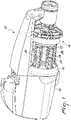
- a generic accumulation yarn feeder 10 comprises a hollow drum 12, which is adapted to carry a variety of yarn loops (not shown) that form a reserve wound thereon.
- the yarn is adapted to unwind from the drum 12 when drawn by a generic downstream textile machine (not shown).
- a weft braking device 14 which controls its mechanical tension.
- the weft braking device 14, which is not part of the aim and objects of the present invention, can be of the conventional type and therefore it will not be described herein in detail.
- winding means which in this embodiment comprise a motorized flywheel 16, wind on the drum 12new yarn taken from an upstream supply spool (not shown).
- the flywheel 16 rotates coaxially to the drum 12 under the actuation of a motor 18.
- the yarn feeder 10 is provided with a spacer device 20 the purpose of which is to keep the loops of yarn wound on the drum 12 mutually regularly spaced, so as to ensure a smooth and regular unwinding of the yarn from the drum 12, also as a function of the tension control to which the yarn is subjected by the weft braking device 14.
- the spacer device 20 can comprise a hub 22 from which a series of spokes 24, for example, five mutually angularly equidistant spokes 24, protrudes radially.
- the spokes 24 support respective fingers 26 at their external ends, which extend in a substantially longitudinal direction with respect to the axis of the hub.
- the hub 22 is fitted freely on the driving shaft 30 that turns the flywheel 16, with the fingers 26 inserted in respective longitudinal slits 28 provided on the drum 12.
- the fingers 26 are rendered integral in rotation with the drum 12 in the manner that will be described in detail hereinafter.
- At least one rolling bearing - two bearings 31 in this embodiment ( Figure 4 ) - and a bush 32 ( Figure 3 ) keyed on the driving shaft 30 are interposed between the hub 22 and the driving shaft 30.
- the bush 32 has an external cylindrical surface, which is engaged by the internal rings of the rolling bearings 31, that has an axis that is oblique with respect to the axis of the driving shaft 30.
- the fingers 26 are connected to the drum 12 by a joint 33 which is configured to prevent the rotation of the fingers 26 around the axis of the drum 12 and at the same time allow said oscillating motion.
- the joint 33 comprises a hollow body 34 which is formed in one piece and has an internal annular portion 36 provided with a series of first internal longitudinal slots 38 which engage, in a per se axially free manner, corresponding longitudinal protrusions 58 which are integral with the drum 12, so as to render the internal annular portion 36 integral in rotation with the drum 12, an external annular portion 40 provided with a series of external longitudinal slots 42 which engage, in a per se axially free manner, corresponding longitudinal ribs 46 provided on the fingers 26, so as to render the external annular portion integral in rotation with the fingers 26, and an intermediate portion 48 which is yielding in a longitudinal direction and is substantially rigid in torsion.
- the internal annular portion 36 is axially blocked with respect to the drum 12 and, for this purpose, it is sandwiched, by clamping means which will be described in greater detail hereinafter, between an abutment 50 that is integral with the drum 12 and a flange 54.
- the abutment 50 has a substantially tubular profile, is accommodated coaxially inside the drum 12, and has a series of second internal longitudinal slots 52 ( Figure 3 ) aligned with the first ones; the longitudinal protrusions 58 being provided on a tubular extension 56 of the flange 54 and engaging both the first internal longitudinal slots 38 and the second internal longitudinal slots 52.
- the hollow body 34 is made of a material that can flex elastically, advantageously neoprene or chloroprene.
- the intermediate portion 48 preferably has a thin-walled profile extending in a radial direction, and at least one corrugation in order to ensure suitable yielding in a longitudinal direction.
- the external longitudinal slots 42 are provided on respective radial protrusions 57 which extend monolithically outward from the external annular portion 40.
- the flange 54 has an outer flat portion 54a and an inner conical portion 54b which engages externally a corresponding bevel 59 provided on the internal tubular portion 36.
- the clamping means comprise a bushing 60 which is threaded internally ( Figure 4 ), is accommodated in the abutment 50 and is integral therewith, and a first screw 62 which is inserted in the flange 54 and is screwed to one end of the bushing 60.
- a screw provided with a conical head is used in order to engage the conical portion 54b of the flange 54 to ensure correct centering.
- the abutment 50 is fixed to a front wall 12a of the drum 12 by means of a second screw 64 which is provided with a knob 66 for manual tightening.
- the second screw 64 is inserted in the front wall 12a and is screwed to the opposite end of the bushing 60 with respect to the first screw 62.
- the external tubular portion 40 of the hollow body 34 is delimited axially between a first flat end surface 40a which faces the hub 22 and a second flat end surface 40b which faces the front wall 12a of the drum 12.
- the first flat end surface 40a has an annular groove 68 which engages, for centering purposes, a corresponding annular lip 22a which extends axially from the end of the hub 22.
- the abutment 50 has an appendage 70 for supporting sensors and any other accessory devices that lie outside the aim and objects of the present invention.
- the hollow body 22 prevents the rotation of the hub 22 and of the fingers 26 with respect to the drum 12 but, by deforming in the region of the intermediate portion 48, allows the above mentioned oscillating motion.
- the assembly of the spacer device 20, and particularly of the joint 33, in the drum 12 is very easy.
- the hollow body 34 can be fixed to the abutment 50 by means of the flange 54 and the first screw 62.
- the drum can be fixed to the body of the feeder 10.
- the manufacture of the joint according to the invention does not require particular treatments and therefore is much cheaper than known solutions, which are based on vulcanization treatments.
- FIG. 5 shows a further embodiment of the invention, in which elements similar or identical to those of the previous embodiment are designated by the same reference numeral increased by 100.
- this embodiment differs from the preceding one in that the longitudinal protrusions 158, which engage the first internal longitudinal slots 138 of the internal annular portion 136 of the hollow body 134, are provided on a tubular extension 156 which is integral with the abutment 150, and the internal annular portion 136 is sandwiched between the abutment 150 and a washer 154, which takes the place of the flange of the previous embodiment, by virtue of a screw 162 screwed on the tubular extension 156.
- the longitudinal slots which acts as rotational coupling surfaces
- the longitudinal protrusions and the longitudinal ribs which act as rotational coupling counter-surfaces
- the rotational coupling may be provided differently, for example, by engagement between polygonal surfaces.
- the mechanism that produces the oscillation of the fingers lies completely outside the aim and objects of the present invention and may be provided differently from what is described here and illustrated by way of example, for example, with systems based on cams or on articulated levers.
- the shape of the hollow body 34 also may be modified within the limits of what is claimed.
- the intermediate portion could be extended in an axial direction instead of radially as in the example described herein, and/or it might have a greater number of corrugations.
Landscapes
- Engineering & Computer Science (AREA)
- Textile Engineering (AREA)
- Forwarding And Storing Of Filamentary Material (AREA)
Claims (15)
- Ein Speicherfadenzuführer, der eine hohle Trommel (12) umfasst, auf welche motorisierte Wicklungsmittel (16) Fadenschlaufen aufwickeln, und eine Abstandsvorrichtung (20), versehen mit einer Reihe von Fingern (26), welche in entsprechende Längsschlitze (28) der Trommel (12) eingeführt und mit einer oszillierenden Bewegung angetrieben werden, die eine Längskomponente hat, um die progressive Vorwärtsbewegung der Fadenschlaufen beim gleichzeitigen Aufwickeln auf die Trommel (12) sicherzustellen; wobei die Finger (26) mit der Trommel (12) über ein teilweise elastisches Verbindungselement (33) verbunden sind, welches ausgebildet ist, um die Drehung der Finger (26) um die Achse der Trommel (12) zu verhindern und um die oszillierende Bewegung zu ermöglichen; wobei das Verbindungselement (33) einen Hohlkörper (34) umfasst, der einteilig geformt ist; dadurch gekennzeichnet, dass das Verbindungselement Folgendes hat:- einen ringförmigen inneren Abschnitt (36), ausgestattet mit ersten Drehkopplungs-Oberflächen (38), welche auf eine an sich axial freie Art mit entsprechenden ersten Drehkopplungs-Gegenflächen (58) in Eingriff stehen, die mit der Trommel (12) integral sind, um so den ringförmigen inneren Abschnitt (36) in der Drehung integral mit der Trommel (12) zu machen,- einen ringförmigen äußeren Abschnitt (40), ausgestattet mit zweiten Drehkopplungs-Oberflächen (42), welche auf eine an sich axial freie Art mit entsprechenden zweiten Drehkopplungs-Gegenflächen (46) in Eingriff stehen, die mit den Fingern (26) integral sind, um so den ringförmigen äußeren Abschnitt (40) in der Drehung integral mit den Fingern (26) zu machen, und- einen intermediären Abschnitt (48), der in einer Längsrichtung elastisch und in der Torsion im Wesentlichen starr ist.
- Der Speicherfadenzuführer gemäß Anspruch 1, dadurch gekennzeichnet, dass der ringförmige innere Abschnitt (36) durch Klemmmittel (60, 62) zwischen einem Widerlager (50), das integral mit der Trommel (12) ist, und einem Flansch (54) eingeschlossen ist.
- Der Speicherfadenzuführer gemäß Anspruch 2, dadurch gekennzeichnet, dass das Widerlager (50) ein im Wesentlichen rohrförmiges Profil hat und mit dritten Drehkopplungs-Oberflächen (52) ausgestattet ist, die mit den ersten Drehkopplungs-Oberflächen (38) ausgerichtet sind; wobei die ersten Drehkopplungs-Gegenflächen (58) an einer rohrförmigen Verlängerung (56) des Flanschs (54) angebracht sind und sowohl mit den ersten Drehkopplungs-Oberflächen (38) als auch mit den dritten Drehkopplungs-Oberflächen (52) in Eingriff stehen.
- Der Speicherfadenzuführer gemäß Anspruch 3, dadurch gekennzeichnet, dass die ersten Drehkopplungs-Oberflächen eine Reihe innerer Längsschlitze (38) umfassen, die an dem ringförmigen inneren Abschnitt (36) angebracht sind, wobei die dritten Drehkopplungs-Oberflächen eine Reihe innerer Längsschlitze (52) umfassen, die an dem Widerlager (50) angebracht sind, und die ersten Drehkopplungs-Gegenflächen eine Reihe länglicher Vorsprünge (58) umfassen, welche in die ersten inneren Längsschlitze (38) und die zweiten inneren Längsschlitze (52) eingeführt sind.
- Der Speicherfadenzuführer gemäß einem der Ansprüche 1-4, dadurch gekennzeichnet, dass die zweiten Drehkopplungs-Oberflächen eine Reihe äußerer Längsschlitze (42) umfassen und die zweiten Drehkopplungs-Gegenflächen eine Reihe entsprechender Längsrippen (46) umfassen, die an den Fingern (26) angebracht sind.
- Der Speicherfadenzuführer gemäß Anspruch 5, dadurch gekennzeichnet, dass die äußeren Längsschlitze (42) an den Enden entsprechender radialer Vorsprünge (57) angebracht sind, die sich monolithisch von dem ringförmigen äußeren Abschnitt (40) nach außen erstrecken.
- Der Speicherfadenzuführer gemäß einem der Ansprüche 3-6, dadurch gekennzeichnet, dass die Klemmmittel eine Buchse (60) umfassen, die ein Innengewinde hat und in das Widerlager (50) eingeführt ist, und eine erste Schraube (62), die in den Flansch (54) eingesetzt und mit einem Ende der Buchse (60) verschraubt ist.
- Der Speicherfadenzuführer gemäß Anspruch 7, dadurch gekennzeichnet, dass das Widerlager (50) an einer vorderen Wand (12a) der Trommel (12) mit Hilfe einer zweiten Schraube (64) befestigt ist, die in die vordere Wand (12a) eingeführt und mit dem gegenüberliegenden Ende der Buchse (60) verschraubt ist.
- Der Speicherfadenzuführer gemäß Anspruch 8, dadurch gekennzeichnet, dass die zweite Schraube (64) mit einem Knopf (66) zum manuellen Festziehen ausgestattet ist.
- Der Speicherfadenzuführer gemäß einem der Ansprüche 1-9, wobei die Finger integral mit einer Nabe (22) sind, die koaxial mit der Trommel (12) ist, dadurch gekennzeichnet, dass der äußere rohrförmige Abschnitt (40) axial von einer flachen Oberfläche (40a) begrenzt ist, die der Nabe (22) zugewandt und mit einer Ringnut (68) versehen ist, welche zum Zwecke der Zentrierung mit einer entsprechenden ringförmigen Lippe (22a) in Eingriff steht, die sich axial von der Nabe (22) erstreckt.
- Der Speicherfadenzuführer gemäß einem der Ansprüche 1-10, dadurch gekennzeichnet, dass der Hohlkörper (34) aus einem elastisch nachgebenden Material besteht.
- Der Speicherfadenzuführer gemäß einem der Ansprüche 1-11, dadurch gekennzeichnet, dass der intermediäre Abschnitt (48) ein dünnwandiges Profil hat, das sich in eine radiale Richtung erstreckt.
- Der Speicherfadenzuführer gemäß einem der Ansprüche 1-12, dadurch gekennzeichnet, dass der intermediäre Abschnitt (48) mindestens eine Riffelung hat.
- Der Speicherfadenzuführer gemäß Anspruch 2, dadurch gekennzeichnet, dass das Widerlager (50) ein im Wesentlichen rohrförmiges Profil hat und die ersten Drehkopplungs-Gegenflächen (158) an dem Widerlager (150) angebracht sind.
- Der Speicherfadenzuführer gemäß Anspruch 14, dadurch gekennzeichnet, dass die ersten Drehkopplungs-Oberflächen eine Reihe innerer Längsschlitze (138) umfassen, die an den ringförmigen inneren Abschnitt (136) angebracht sind, und die ersten Drehkopplungs-Gegenflächen eine Reihe länglicher Vorsprünge (158) umfassen, die an einer rohrförmigen Verlängerung (156) des Widerlagers (150) angebracht und in die ersten inneren Längsschlitze (138) eingeführt sind.
Applications Claiming Priority (1)
| Application Number | Priority Date | Filing Date | Title |
|---|---|---|---|
| IT102020000018535A IT202000018535A1 (it) | 2020-07-30 | 2020-07-30 | Alimentatore di filato ad accumulo provvisto di dispositivo distanziatore per la separazione delle spire di filato avvolte sul tamburo. |
Publications (2)
| Publication Number | Publication Date |
|---|---|
| EP3945150A1 EP3945150A1 (de) | 2022-02-02 |
| EP3945150B1 true EP3945150B1 (de) | 2023-01-25 |
Family
ID=72801974
Family Applications (1)
| Application Number | Title | Priority Date | Filing Date |
|---|---|---|---|
| EP21176649.8A Active EP3945150B1 (de) | 2020-07-30 | 2021-05-28 | Speicherfadenzuführer mit abstandsvorrichtung zur trennung der auf die trommel gewickelten fadenschlaufen |
Country Status (3)
| Country | Link |
|---|---|
| EP (1) | EP3945150B1 (de) |
| CN (2) | CN216712386U (de) |
| IT (1) | IT202000018535A1 (de) |
Families Citing this family (2)
| Publication number | Priority date | Publication date | Assignee | Title |
|---|---|---|---|---|
| IT202000018535A1 (it) * | 2020-07-30 | 2022-01-30 | Lgl Electronics Spa | Alimentatore di filato ad accumulo provvisto di dispositivo distanziatore per la separazione delle spire di filato avvolte sul tamburo. |
| CN121849728A (zh) * | 2024-10-11 | 2026-04-14 | 爱吉尔电子股份公司 | 设置有线圈间隔装置的累积式纱线进给器 |
Family Cites Families (8)
| Publication number | Priority date | Publication date | Assignee | Title |
|---|---|---|---|---|
| IT1204330B (it) * | 1986-04-30 | 1989-03-01 | Sarfati & Vischiani Spa | Dispositivo accumulatore per alimentatori di filo di trama a macchine tessili |
| JP3381337B2 (ja) * | 1993-11-09 | 2003-02-24 | 株式会社豊田自動織機 | ジェットルームにおける緯糸測長貯留装置 |
| IT239807Y1 (it) * | 1996-09-11 | 2001-03-13 | Lgl Electronics Spa | Dispositivo perfezionato di separazione delle spire di filato perapparecchi alimentatori di trama |
| JP2000073255A (ja) * | 1998-08-24 | 2000-03-07 | Tsudakoma Corp | 緯糸測長貯留装置における測長量の調節設定装置 |
| DE10054103A1 (de) * | 2000-10-31 | 2002-05-08 | Iro Patent Ag Baar | Fadenliefergerät |
| IT201800005191A1 (it) * | 2018-05-09 | 2019-11-09 | Porgitrama per macchine tessili con tamburo a diametro regolabile | |
| DE102018115631A1 (de) * | 2018-06-28 | 2020-01-02 | Memminger-Iro Gmbh | Fadenliefergerät und System mit einem Fadenliefergerät |
| IT202000018535A1 (it) * | 2020-07-30 | 2022-01-30 | Lgl Electronics Spa | Alimentatore di filato ad accumulo provvisto di dispositivo distanziatore per la separazione delle spire di filato avvolte sul tamburo. |
-
2020
- 2020-07-30 IT IT102020000018535A patent/IT202000018535A1/it unknown
-
2021
- 2021-04-27 CN CN202120891658.1U patent/CN216712386U/zh not_active Withdrawn - After Issue
- 2021-04-27 CN CN202110458497.1A patent/CN114059222B/zh active Active
- 2021-05-28 EP EP21176649.8A patent/EP3945150B1/de active Active
Also Published As
| Publication number | Publication date |
|---|---|
| CN114059222B (zh) | 2026-03-10 |
| CN114059222A (zh) | 2022-02-18 |
| CN216712386U (zh) | 2022-06-10 |
| EP3945150A1 (de) | 2022-02-02 |
| IT202000018535A1 (it) | 2022-01-30 |
Similar Documents
| Publication | Publication Date | Title |
|---|---|---|
| EP3945150B1 (de) | Speicherfadenzuführer mit abstandsvorrichtung zur trennung der auf die trommel gewickelten fadenschlaufen | |
| US6350204B1 (en) | Fiber-reinforced plastic pipe | |
| CA2187377A1 (en) | Tubular core assemblies for rolls of paper or other sheet material | |
| JP2018507832A (ja) | 巻き取り機 | |
| EP0821130B1 (de) | Eine Rollvorrichtung zum Aufrollen und Spannen eines flexiblen Elementes wie z.B. eine Materialbahn, ein Rolladen oder dergleichen, insbesondere zum Schutze von Maschinen | |
| EP0663365A4 (de) | Spulenhalter und aufwickelvorrichtung mit einem solchen spulenhalter. | |
| US11634945B2 (en) | Roller blind, process for manufacturing same and roller blind system with such a roller blind | |
| EP2218670B1 (de) | Fadenliefervorrichtung mit einer leichten Fadenaufwickeltrommel | |
| JPH0362818B2 (de) | ||
| CA2121277A1 (en) | Tubular Core Assembly for Winding Paper and Other Sheet Material Having Mechanically Interlocked End Members | |
| CA2509174A1 (en) | Paint roller | |
| JP4149920B2 (ja) | 可撓性プレスカバーおよびこのような可撓性プレスカバーを有するシュープレスロール | |
| US3783481A (en) | Curved roll | |
| EP3608460B1 (de) | Schussfadenbremsvorrichtung für speicherfadenzuführvorrichtungen | |
| EP3057898B1 (de) | Wickelstange für bahnmaterialrollen und wickelmaschine mit dieser stange | |
| CN208249566U (zh) | 一种机械式气胀轴 | |
| CN212402978U (zh) | 一种络筒机卷筒固定装置 | |
| BR112020020028A2 (pt) | Um tubo composto rígido para enrolamento de fios | |
| KR20070086368A (ko) | 고강성 권취 코어 | |
| EP1164103B1 (de) | Bremse für eine selbstregulierende Fadenbremse einer Schussfadenliefervorrichtung | |
| JP5393247B2 (ja) | テープ巻き付け装置、及びテープ巻き付け方法 | |
| US881149A (en) | Reel for winding-machines. | |
| EP0968949B1 (de) | Schussfadenliefervorrichtung für Webmaschinen mit verbesserte Mittel zum Vorschub und Trennen von Schussfadenreservewindungen | |
| CN107406214B (zh) | 卷绕机 | |
| JP6856538B2 (ja) | 巻取りスピンドル |
Legal Events
| Date | Code | Title | Description |
|---|---|---|---|
| PUAI | Public reference made under article 153(3) epc to a published international application that has entered the european phase |
Free format text: ORIGINAL CODE: 0009012 |
|
| STAA | Information on the status of an ep patent application or granted ep patent |
Free format text: STATUS: THE APPLICATION HAS BEEN PUBLISHED |
|
| AK | Designated contracting states |
Kind code of ref document: A1 Designated state(s): AL AT BE BG CH CY CZ DE DK EE ES FI FR GB GR HR HU IE IS IT LI LT LU LV MC MK MT NL NO PL PT RO RS SE SI SK SM TR |
|
| STAA | Information on the status of an ep patent application or granted ep patent |
Free format text: STATUS: REQUEST FOR EXAMINATION WAS MADE |
|
| 17P | Request for examination filed |
Effective date: 20220303 |
|
| RBV | Designated contracting states (corrected) |
Designated state(s): AL AT BE BG CH CY CZ DE DK EE ES FI FR GB GR HR HU IE IS IT LI LT LU LV MC MK MT NL NO PL PT RO RS SE SI SK SM TR |
|
| RIC1 | Information provided on ipc code assigned before grant |
Ipc: D03D 47/36 20060101AFI20220704BHEP |
|
| GRAP | Despatch of communication of intention to grant a patent |
Free format text: ORIGINAL CODE: EPIDOSNIGR1 |
|
| STAA | Information on the status of an ep patent application or granted ep patent |
Free format text: STATUS: GRANT OF PATENT IS INTENDED |
|
| INTG | Intention to grant announced |
Effective date: 20220907 |
|
| GRAS | Grant fee paid |
Free format text: ORIGINAL CODE: EPIDOSNIGR3 |
|
| GRAA | (expected) grant |
Free format text: ORIGINAL CODE: 0009210 |
|
| STAA | Information on the status of an ep patent application or granted ep patent |
Free format text: STATUS: THE PATENT HAS BEEN GRANTED |
|
| AK | Designated contracting states |
Kind code of ref document: B1 Designated state(s): AL AT BE BG CH CY CZ DE DK EE ES FI FR GB GR HR HU IE IS IT LI LT LU LV MC MK MT NL NO PL PT RO RS SE SI SK SM TR |
|
| REG | Reference to a national code |
Ref country code: GB Ref legal event code: FG4D |
|
| REG | Reference to a national code |
Ref country code: CH Ref legal event code: EP |
|
| REG | Reference to a national code |
Ref country code: AT Ref legal event code: REF Ref document number: 1545970 Country of ref document: AT Kind code of ref document: T Effective date: 20230215 Ref country code: IE Ref legal event code: FG4D |
|
| REG | Reference to a national code |
Ref country code: DE Ref legal event code: R096 Ref document number: 602021001310 Country of ref document: DE |
|
| REG | Reference to a national code |
Ref country code: LT Ref legal event code: MG9D |
|
| REG | Reference to a national code |
Ref country code: NL Ref legal event code: MP Effective date: 20230125 |
|
| REG | Reference to a national code |
Ref country code: AT Ref legal event code: MK05 Ref document number: 1545970 Country of ref document: AT Kind code of ref document: T Effective date: 20230125 |
|
| PG25 | Lapsed in a contracting state [announced via postgrant information from national office to epo] |
Ref country code: NL Free format text: LAPSE BECAUSE OF FAILURE TO SUBMIT A TRANSLATION OF THE DESCRIPTION OR TO PAY THE FEE WITHIN THE PRESCRIBED TIME-LIMIT Effective date: 20230125 |
|
| P01 | Opt-out of the competence of the unified patent court (upc) registered |
Effective date: 20230527 |
|
| PG25 | Lapsed in a contracting state [announced via postgrant information from national office to epo] |
Ref country code: RS Free format text: LAPSE BECAUSE OF FAILURE TO SUBMIT A TRANSLATION OF THE DESCRIPTION OR TO PAY THE FEE WITHIN THE PRESCRIBED TIME-LIMIT Effective date: 20230125 Ref country code: PT Free format text: LAPSE BECAUSE OF FAILURE TO SUBMIT A TRANSLATION OF THE DESCRIPTION OR TO PAY THE FEE WITHIN THE PRESCRIBED TIME-LIMIT Effective date: 20230525 Ref country code: NO Free format text: LAPSE BECAUSE OF FAILURE TO SUBMIT A TRANSLATION OF THE DESCRIPTION OR TO PAY THE FEE WITHIN THE PRESCRIBED TIME-LIMIT Effective date: 20230425 Ref country code: LV Free format text: LAPSE BECAUSE OF FAILURE TO SUBMIT A TRANSLATION OF THE DESCRIPTION OR TO PAY THE FEE WITHIN THE PRESCRIBED TIME-LIMIT Effective date: 20230125 Ref country code: LT Free format text: LAPSE BECAUSE OF FAILURE TO SUBMIT A TRANSLATION OF THE DESCRIPTION OR TO PAY THE FEE WITHIN THE PRESCRIBED TIME-LIMIT Effective date: 20230125 Ref country code: HR Free format text: LAPSE BECAUSE OF FAILURE TO SUBMIT A TRANSLATION OF THE DESCRIPTION OR TO PAY THE FEE WITHIN THE PRESCRIBED TIME-LIMIT Effective date: 20230125 Ref country code: ES Free format text: LAPSE BECAUSE OF FAILURE TO SUBMIT A TRANSLATION OF THE DESCRIPTION OR TO PAY THE FEE WITHIN THE PRESCRIBED TIME-LIMIT Effective date: 20230125 Ref country code: AT Free format text: LAPSE BECAUSE OF FAILURE TO SUBMIT A TRANSLATION OF THE DESCRIPTION OR TO PAY THE FEE WITHIN THE PRESCRIBED TIME-LIMIT Effective date: 20230125 |
|
| PG25 | Lapsed in a contracting state [announced via postgrant information from national office to epo] |
Ref country code: SE Free format text: LAPSE BECAUSE OF FAILURE TO SUBMIT A TRANSLATION OF THE DESCRIPTION OR TO PAY THE FEE WITHIN THE PRESCRIBED TIME-LIMIT Effective date: 20230125 Ref country code: PL Free format text: LAPSE BECAUSE OF FAILURE TO SUBMIT A TRANSLATION OF THE DESCRIPTION OR TO PAY THE FEE WITHIN THE PRESCRIBED TIME-LIMIT Effective date: 20230125 Ref country code: IS Free format text: LAPSE BECAUSE OF FAILURE TO SUBMIT A TRANSLATION OF THE DESCRIPTION OR TO PAY THE FEE WITHIN THE PRESCRIBED TIME-LIMIT Effective date: 20230525 Ref country code: GR Free format text: LAPSE BECAUSE OF FAILURE TO SUBMIT A TRANSLATION OF THE DESCRIPTION OR TO PAY THE FEE WITHIN THE PRESCRIBED TIME-LIMIT Effective date: 20230426 Ref country code: FI Free format text: LAPSE BECAUSE OF FAILURE TO SUBMIT A TRANSLATION OF THE DESCRIPTION OR TO PAY THE FEE WITHIN THE PRESCRIBED TIME-LIMIT Effective date: 20230125 |
|
| REG | Reference to a national code |
Ref country code: DE Ref legal event code: R097 Ref document number: 602021001310 Country of ref document: DE |
|
| PG25 | Lapsed in a contracting state [announced via postgrant information from national office to epo] |
Ref country code: SM Free format text: LAPSE BECAUSE OF FAILURE TO SUBMIT A TRANSLATION OF THE DESCRIPTION OR TO PAY THE FEE WITHIN THE PRESCRIBED TIME-LIMIT Effective date: 20230125 Ref country code: RO Free format text: LAPSE BECAUSE OF FAILURE TO SUBMIT A TRANSLATION OF THE DESCRIPTION OR TO PAY THE FEE WITHIN THE PRESCRIBED TIME-LIMIT Effective date: 20230125 Ref country code: EE Free format text: LAPSE BECAUSE OF FAILURE TO SUBMIT A TRANSLATION OF THE DESCRIPTION OR TO PAY THE FEE WITHIN THE PRESCRIBED TIME-LIMIT Effective date: 20230125 Ref country code: DK Free format text: LAPSE BECAUSE OF FAILURE TO SUBMIT A TRANSLATION OF THE DESCRIPTION OR TO PAY THE FEE WITHIN THE PRESCRIBED TIME-LIMIT Effective date: 20230125 Ref country code: CZ Free format text: LAPSE BECAUSE OF FAILURE TO SUBMIT A TRANSLATION OF THE DESCRIPTION OR TO PAY THE FEE WITHIN THE PRESCRIBED TIME-LIMIT Effective date: 20230125 |
|
| PG25 | Lapsed in a contracting state [announced via postgrant information from national office to epo] |
Ref country code: SK Free format text: LAPSE BECAUSE OF FAILURE TO SUBMIT A TRANSLATION OF THE DESCRIPTION OR TO PAY THE FEE WITHIN THE PRESCRIBED TIME-LIMIT Effective date: 20230125 |
|
| PLBE | No opposition filed within time limit |
Free format text: ORIGINAL CODE: 0009261 |
|
| STAA | Information on the status of an ep patent application or granted ep patent |
Free format text: STATUS: NO OPPOSITION FILED WITHIN TIME LIMIT |
|
| 26N | No opposition filed |
Effective date: 20231026 |
|
| PG25 | Lapsed in a contracting state [announced via postgrant information from national office to epo] |
Ref country code: MC Free format text: LAPSE BECAUSE OF FAILURE TO SUBMIT A TRANSLATION OF THE DESCRIPTION OR TO PAY THE FEE WITHIN THE PRESCRIBED TIME-LIMIT Effective date: 20230125 |
|
| PG25 | Lapsed in a contracting state [announced via postgrant information from national office to epo] |
Ref country code: SI Free format text: LAPSE BECAUSE OF FAILURE TO SUBMIT A TRANSLATION OF THE DESCRIPTION OR TO PAY THE FEE WITHIN THE PRESCRIBED TIME-LIMIT Effective date: 20230125 Ref country code: MC Free format text: LAPSE BECAUSE OF FAILURE TO SUBMIT A TRANSLATION OF THE DESCRIPTION OR TO PAY THE FEE WITHIN THE PRESCRIBED TIME-LIMIT Effective date: 20230125 Ref country code: LU Free format text: LAPSE BECAUSE OF NON-PAYMENT OF DUE FEES Effective date: 20230528 |
|
| REG | Reference to a national code |
Ref country code: IE Ref legal event code: MM4A |
|
| PG25 | Lapsed in a contracting state [announced via postgrant information from national office to epo] |
Ref country code: IE Free format text: LAPSE BECAUSE OF NON-PAYMENT OF DUE FEES Effective date: 20230528 |
|
| PG25 | Lapsed in a contracting state [announced via postgrant information from national office to epo] |
Ref country code: IE Free format text: LAPSE BECAUSE OF NON-PAYMENT OF DUE FEES Effective date: 20230528 |
|
| PG25 | Lapsed in a contracting state [announced via postgrant information from national office to epo] |
Ref country code: FR Free format text: LAPSE BECAUSE OF NON-PAYMENT OF DUE FEES Effective date: 20230531 |
|
| PG25 | Lapsed in a contracting state [announced via postgrant information from national office to epo] |
Ref country code: BG Free format text: LAPSE BECAUSE OF FAILURE TO SUBMIT A TRANSLATION OF THE DESCRIPTION OR TO PAY THE FEE WITHIN THE PRESCRIBED TIME-LIMIT Effective date: 20230125 |
|
| PG25 | Lapsed in a contracting state [announced via postgrant information from national office to epo] |
Ref country code: BG Free format text: LAPSE BECAUSE OF FAILURE TO SUBMIT A TRANSLATION OF THE DESCRIPTION OR TO PAY THE FEE WITHIN THE PRESCRIBED TIME-LIMIT Effective date: 20230125 |
|
| REG | Reference to a national code |
Ref country code: CH Ref legal event code: PL |
|
| PG25 | Lapsed in a contracting state [announced via postgrant information from national office to epo] |
Ref country code: CH Free format text: LAPSE BECAUSE OF NON-PAYMENT OF DUE FEES Effective date: 20240531 |
|
| PGFP | Annual fee paid to national office [announced via postgrant information from national office to epo] |
Ref country code: DE Payment date: 20250516 Year of fee payment: 5 |
|
| PGFP | Annual fee paid to national office [announced via postgrant information from national office to epo] |
Ref country code: GB Payment date: 20250520 Year of fee payment: 5 |
|
| PGFP | Annual fee paid to national office [announced via postgrant information from national office to epo] |
Ref country code: BE Payment date: 20250516 Year of fee payment: 5 Ref country code: IT Payment date: 20250422 Year of fee payment: 5 |
|
| PG25 | Lapsed in a contracting state [announced via postgrant information from national office to epo] |
Ref country code: CY Free format text: LAPSE BECAUSE OF FAILURE TO SUBMIT A TRANSLATION OF THE DESCRIPTION OR TO PAY THE FEE WITHIN THE PRESCRIBED TIME-LIMIT; INVALID AB INITIO Effective date: 20210528 |
|
| PGFP | Annual fee paid to national office [announced via postgrant information from national office to epo] |
Ref country code: TR Payment date: 20250522 Year of fee payment: 5 |
|
| PG25 | Lapsed in a contracting state [announced via postgrant information from national office to epo] |
Ref country code: HU Free format text: LAPSE BECAUSE OF FAILURE TO SUBMIT A TRANSLATION OF THE DESCRIPTION OR TO PAY THE FEE WITHIN THE PRESCRIBED TIME-LIMIT; INVALID AB INITIO Effective date: 20210528 |