EP3945007A1 - Kettensteganordnung für eine laufwerkskette eines kettenfahrzeugs - Google Patents
Kettensteganordnung für eine laufwerkskette eines kettenfahrzeugs Download PDFInfo
- Publication number
- EP3945007A1 EP3945007A1 EP21186565.4A EP21186565A EP3945007A1 EP 3945007 A1 EP3945007 A1 EP 3945007A1 EP 21186565 A EP21186565 A EP 21186565A EP 3945007 A1 EP3945007 A1 EP 3945007A1
- Authority
- EP
- European Patent Office
- Prior art keywords
- chain
- track bracket
- stud
- arrangement
- track
- Prior art date
- Legal status (The legal status is an assumption and is not a legal conclusion. Google has not performed a legal analysis and makes no representation as to the accuracy of the status listed.)
- Granted
Links
Images



Classifications
-
- B—PERFORMING OPERATIONS; TRANSPORTING
- B62—LAND VEHICLES FOR TRAVELLING OTHERWISE THAN ON RAILS
- B62D—MOTOR VEHICLES; TRAILERS
- B62D55/00—Endless track vehicles
- B62D55/08—Endless track units; Parts thereof
- B62D55/18—Tracks
- B62D55/24—Tracks of continuously flexible type, e.g. rubber belts
- B62D55/253—Tracks of continuously flexible type, e.g. rubber belts having elements interconnected by one or more cables or like elements
-
- B—PERFORMING OPERATIONS; TRANSPORTING
- B62—LAND VEHICLES FOR TRAVELLING OTHERWISE THAN ON RAILS
- B62D—MOTOR VEHICLES; TRAILERS
- B62D55/00—Endless track vehicles
- B62D55/08—Endless track units; Parts thereof
- B62D55/18—Tracks
- B62D55/26—Ground engaging parts or elements
Definitions
- the invention relates to a chain stay arrangement for a running gear chain of a tracked vehicle, in particular a snow groomer, with a chain stay and with a track bracket fastened to the chain stay.
- a drive chain for a tracked vehicle in the form of a snow groomer is known.
- the carriage chain has a multiplicity of chain stay arrangements, which are fastened transversely to a direction of travel of the chain at regular intervals on a plurality of chain bands that extend parallel to one another in the direction of travel of the chain.
- Each grouser assembly has an outwardly facing grouser and an inwardly facing track bracket.
- the track brackets of the chain stay arrangements are used to guide the carriage chain in the direction of travel of the chain over an end drive wheel and over an opposite end tensioning wheel and over a plurality of running wheels, which form parts of the chain carriage.
- Each track bracket is attached to the corresponding chain stay using screw connections.
- the object of the invention is to create a chain stay arrangement of the type mentioned at the outset which has increased durability compared to the prior art.
- the track bow is attached to the chain stud exclusively by gluing, and that the tracking bow is glued to the chain stud via a contact surface which, with an outer contour of the chain stud, defines an adhesive gap with a U-shaped cross section that extends over an entire Length of the track bracket - seen in the longitudinal direction of the chain bar - is extended.
- the yoke is preferably made of steel and the chain stay is made of an aluminum alloy.
- a suitable adhesive for gluing such a track bracket to the chain stud ensures that the track bracket is not rigidly connected to the chain stud, but rather is slightly elastically connected to the chain stud over an entire adhesive area. This certain elasticity enables a constant connection between the track bracket and the chain stud even when a tracked vehicle provided with such a chain stud arrangement is being driven. Because the bonding avoids stress peaks due to bending that occurs when driving. With known screw connections of the track bracket to the chain stay, however, the slight deflection of the chain stay leads to shearing stresses in the screw connections when driving.
- the track bracket is connected to the chain stud exclusively via a suitable adhesive and that there is no additional screw connection.
- the bonding ensures that no overloading occurs in the connection area between the track bracket and the chain bar when a tracked vehicle is being driven.
- the solution according to the invention is also suitable for chain stay arrangements whose parts, such as in particular the chain stay and track bracket, are made of other metallic materials or of non-metallic materials. In particular, it is possible to produce the track bracket from plastic and the chain stay from metal.
- both the chain stud and the track bracket from a non-metallic material also falls within the scope of the solution according to the invention.
- the solution according to the invention has particularly great advantages for a chain stay arrangement in which both the chain stay and the track bracket are made of a metallic material.
- the solution according to the invention can be used in a particularly advantageous manner for a snow groomer which is provided for the maintenance and shaping of snowy terrain and for this purpose has attachments on the front and rear.
- a one-component, moisture-reactive polyurethane adhesive which has good adhesion, high staying power and high elasticity, is advantageously suitable for a chain stay arrangement of a snow groomer, in which both the chain stay and the track bracket are made of a metallic material.
- Such an adhesive is known in particular under the product name EFBOND DA 183A from EFTEC AG, Switzerland, and is used in vehicle construction together with appropriate primers for bonding windows.
- a two-component adhesive can be used as a suitable adhesive, which has sufficient elasticity in the cured state.
- the track bracket is glued to the chain stud via a contact surface which extends in a U-shape in cross section around a chain stud bottom of the chain stud.
- the three-dimensional contact surface defines, together with corresponding outer contour surfaces of the chain stud base, an at least largely constant adhesive gap over an entire adhesive surface between the track bracket and the chain stud. Due to the fact that the contact surface is raised not only along an underside of the bottom of the chain bar, but also in a U-shape to opposite side surfaces of the bottom of the chain bar, there is a particularly advantageous transmission of force between the track bracket and the chain bar. Because regardless of the corresponding load direction, only shear loads are transmitted through the inevitably also U-shaped adhesive gap surrounding the bottom of the chain bar the adhesive can absorb particularly well due to the even and extensive distribution in the adhesive gap.
- the track bracket is provided with at least one longitudinal profile in the area of its contact surface.
- the at least one longitudinal profiling has surfaces that extend parallel to correspondingly complementary outer contour surfaces of the chain stud base on its underside and on its opposite outer sides.
- the at least one longitudinal profile promotes good adhesive distribution.
- the longitudinal profiling forms a flat and planar contact with an outer contour of the chain stud.
- the longitudinal profiling consequently forms a secure alignment relative to the bottom of the chain stay and the possibility of a secure and stable pre-assembly of the track bracket on the chain stay.
- the longitudinal profiling forms a mechanical support on the bottom of the chain bar due to the level and flat contact and consequently a stable alignment in a pre-assembly position before the adhesive is applied.
- the contact surface has at least one bulge, which is provided in the area of the at least one longitudinal profile.
- the bulge interrupts the level and flat longitudinal profiling and forms an alternative space when the adhesive is introduced, which further improves the distribution of the liquid or free-flowing adhesive.
- At least one spacer web is provided on opposite side surface areas of the contact surface, which extends continuously over the entire length of the contact surface.
- the spacer bars are positioned on opposite longitudinal sides of the chain bar and lie against these outer contour surfaces of the chain bar in order to enable a stable alignment of the track bracket relative to the chain bar and a secure pre-assembly position of the track bracket relative to the chain bar before the adhesive is applied.
- Corresponding groove-shaped or channel-shaped recesses remain on the track bow adjacent to these spacer webs, which define the respective adhesive gap region.
- the at least one spacer bar is adjacent to the adhesive gap and is at least largely flat and flush against the outer contour of the chain bar.
- the spacer webs thus form edges for the adhesive gap, which prevent adhesive from escaping in the area of the spacer webs when it is introduced to the outside exit.
- the installation of the spacer web on the outer contour enables stable support in a pre-assembly position.
- At least one injection channel is provided in the track bracket, which passes through the track bracket from an outside to the contact surface and is designed to inject liquid or free-flowing adhesive into the adhesive gap. It is thus possible in a simple manner in a pre-assembly position, in which the track bracket is mechanically attached to the chain grouser base and provisionally secured, to introduce appropriate liquid or free-flowing adhesive through the injection channel from the outside into the adhesive gap.
- an injection opening on the inlet side of the injection channel is arranged at least largely in the middle between two lateral guide horns of the track bracket.
- the at least largely central orientation is to be understood relative to a longitudinal extension of the track bracket parallel to a longitudinal orientation of the chain stud.
- the at least one injection channel extends at an angle of between 0° and 45° to a vertical axis of the toe bracket.
- the angle range mentioned also includes the angles 0° and 45°.
- the orientation of the at least one injection channel enables an adhesive injection tool to be applied from above or at an angle from the side.
- a tracked vehicle in the form of a snow groomer has, in a way that is not shown in detail, a chain drive which acts as a drive for the snow groomer.
- the chain drive has a drive chain on opposite sides of a vehicle frame of the snow groomer, which during operation is guided around a sprocket wheel, several running wheels and a tensioning wheel.
- Each carriage chain has a plurality of chain belts which extend in the direction of travel of the chain and are arranged parallel to one another and are connected to one another via a large number of chain stay arrangements 1 transversely to the direction of travel of the chain.
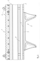
- Each of these grouser assemblies 1 or at least part of the grouser assemblies 1 for the drive chain is according to Figures 1 to 3 designed.
- Each chain stay arrangement 1 has a chain stay 2 made of an aluminum alloy, which, when the carriage chain is assembled and ready for use, extends transversely to the running direction of the chain over a number of chain bands and is connected to these chain bands.
- Each chain band is a rubber band, which is preferably reinforced by fabric inserts.
- the chain bar 2 has a wedge-like cross section. Additional parts 4 are fastened to the chain stud 2 in the area of a tip of the chain stud 2 .
- the additional parts 4 are replaced by a wear rail and several placement bodies for the Wear rail and the chain bar formed.
- the placement bodies have ice gripper and side guide functions.
- the chain stud 2 has a chain stud base 3 , which has an essentially flat bottom side 6 and two essentially flat lateral outer surfaces 10 oriented orthogonally to the bottom side 6 .
- the track bracket 5 has two lateral guide horns, not designated in any more detail, which, when the track bracket 5 is mounted on the chain bar 2 , protrude from the chain bar base 3 in the opposite direction to the tip of the chain bar 2 .
- the track bracket 5 is provided with a fastening area which encompasses a section of the chain stud 2 facing the chain stud bottom 3 in a U-shape on the underside and on the outside.
- This fastening area is recessed over the entire length of the track bracket 5 in the manner of a channel open towards the chain bar 2 .
- the fastening area is formed in that this area is milled out when the track bracket 5 is manufactured.
- the attachment area is also referred to as the contact surface.
- a total of two spacer bars 8 and a longitudinal profile 9 are provided in the channel-like fastening area, whose bottom and side surfaces form the contact surface within the meaning of the invention, which are supported on the bottom side 6 and on the outer surfaces 10 of the chain stud 2.
- Recessed adhesive channels 7 and 11 are provided between the spacer webs 8 and the longitudinal profile 9, the bottom surfaces of which extend continuously as flat surfaces over the entire length of the track bracket 5 and which are essentially parallel to the outer contours (the bottom side 6 and the outer surfaces 10) of the the chain bar base 3 comprehensive section of the chain bar 2 are aligned.
- the chain bar base 3 in the sense of the invention consequently forms the section of the chain bar 2 which is guided on the outside from the base side 6 to a lower edge region of the intermediate bar Z.
- the intermediate bar Z extends parallel to the chain bar base 3 .
- a suitable adhesive K encloses the adhesive space between the contact surface of the fastening area of the track bracket 5 and the outer surfaces of the chain grouser base 3 over a large area and with a material bond.
- the adhesive K is continuously cohesively connected over the entire length of the attachment area of the track bracket 5 to the contact surface of the track bracket 5 on the one hand and the base side 6 and the outer surfaces 10 of the chain grouser base 3 on the other.
- the adhesive K has run in two corner areas of the chain bar base 3 in two V-shaped grooves, which are delimited towards the center by the middle spacer bar 9 and laterally upwards by the respective side spacer bar 8 .
- the adhesive K can also run into the contact areas between the spacer bars 8 and the longitudinal profile 9 and the corresponding outer surfaces of the chain bar base 3 when it is not yet hardened.
- the V-shaped groove areas in which the adhesive K is present are filled with the adhesive K without any air bubbles, specifically over the entire length of the track bracket 5.
- a track bracket 5a after Figures 4 to 9 as well as a track bracket 5b 10 are alternative to the track bracket 5 according to the Figures 1 to 3 for gluing with the chain stay 2 according to 1 and 2 can be used to achieve a further embodiment of a grouser arrangement according to the invention.
- identical or functionally identical sections are provided with the same reference symbols with the addition of the letter a or b.
- the track bar 5a has analogous to the track bar 5 on two lateral guide horns F, according to the Figures 5 to 7 and 9 are arranged in the area of an upper side of the track bracket 5a.
- the underside of the track bracket 5a is also provided with two mutually opposite, lateral spacer webs 8a as well as with a longitudinal profile 9a on a base of the contact surface, which forms the adhesive gap together with the bottom of the chain bar.
- the longitudinal profile 9a is in the middle in the area of the contact surface of the track bracket 5a and extends in the longitudinal direction over almost the entire length of the track bracket 5a.
- the longitudinal profile 9a is flat and flat in order to allow a flush contact with the bottom of the chain bar.
- the longitudinal profile 9a is interrupted by a central bulge 12a and two lateral bulges 12a offset longitudinally from the center, the lateral bulges, which are spaced apart from the central bulge 12a, being smaller than the central bulge.
- the shape and positioning of the bulges 12a is based on the 4 and 6 and 9 clearly recognizable.
- the track bracket 5a is provided with two injection channels 13a which, starting from an upper side of the track bracket 5a, extend centrally between the two guide horns F downward parallel to a central vertical axis and open in the area of the elongated adhesive channels 11a of the adhesive space.
- the two injection channels 13a are each cylindrical and open at the top and bottom. Both injection channels 13a are mirror-symmetrical to a vertical center longitudinal plane of the track bracket 5a, each offset outwards in the track bracket 5a.
- the central bulge 12a is positioned adjacent between the two injection channels 13a.
- liquid or free-flowing adhesive is introduced after the track bracket 5a has been appropriately pre-positioned relative to the chain stud 2 and mechanical, provisional fixing in the area of the chain stud, the adhesive is introduced from the top into the injection channels 13a using a corresponding adhesive injection tool and at least partially runs in the Adhesive gap and into the bulges 12a.
- the track bracket 5b is designed largely identical to that previously based on the Figures 4 to 9 described track bracket 5a. In order to avoid repetition, reference is therefore also made to the comments on the track bracket 5a. Sections of the track bracket 5b that are functionally the same or identical are provided with the same reference numbers, but with the addition of the letter b.
- the track bracket 5b is in the same way alternative to the track bracket 5 with the chain stud 2 of the chain stud arrangement 1 according to 1 connectable, so that what has been said about the chain stud arrangement 1 also applies to the variant of a chain stud arrangement provided with the track bracket 5b.
Landscapes
- Engineering & Computer Science (AREA)
- Chemical & Material Sciences (AREA)
- Combustion & Propulsion (AREA)
- Transportation (AREA)
- Mechanical Engineering (AREA)
- Devices For Conveying Motion By Means Of Endless Flexible Members (AREA)
Abstract
Description
- Die Erfindung betrifft eine Kettensteganordnung für eine Laufwerkskette eines Kettenfahrzeugs, insbesondere einer Pistenraupe, mit einem Kettensteg, sowie mit einem an dem Kettensteg befestigten Spurbügel.
- Aus der
DE 103 20 523 A1 ist eine Laufwerkskette für ein Kettenfahrzeug in Form einer Pistenraupe bekannt. Die Laufwerkskette weist eine Vielzahl von Kettensteganordnungen auf, die quer zu einer Kettenlaufrichtung in gleichmäßigen Abständen auf mehreren parallel zueinander in Kettenlaufrichtung erstreckten Kettenbändern befestigt sind. Jede Kettensteganordnung weist einen nach außen weisenden Kettensteg sowie einen nach innen weisenden Spurbügel auf. Die Spurbügel der Kettensteganordnungen dienen dazu, die Laufwerkskette in Kettenlaufrichtung über ein endseitiges Triebrad sowie über ein gegenüberliegend endseitiges Spannrad und über mehrere Laufräder zu führen, die Teile des Kettenlaufwerks bilden. Jeder Spurbügel ist an dem zugehörigen Kettensteg mithilfe von Schraubverbindungen befestigt. - Aufgabe der Erfindung ist es, eine Kettensteganordnung der eingangs genannten Art zu schaffen, die gegenüber dem Stand der Technik eine erhöhte Haltbarkeit aufweist.
- Diese Aufgabe wird dadurch gelöst, dass der Spurbügel ausschließlich durch Verklebung an dem Kettensteg befestigt ist, und dass der Spurbügel über eine Kontaktfläche mit dem Kettensteg verklebt ist, die mit einer Außenkontur des Kettenstegs einen im Querschnitt U-artigen Klebespalt definiert, der über eine gesamte Länge des Spurbügels - in Längsrichtung des Kettenstegs gesehen - erstreckt ist.
- Der Spurbügel besteht vorzugsweise aus Stahl und der Kettensteg aus einer Aluminiumlegierung. Ein geeigneter Klebstoff zur Verklebung eines solchen Spurbügels mit dem Kettensteg gewährleistet, dass der Spurbügel nicht steif mit dem Kettensteg verbunden ist, sondern vielmehr über eine gesamte Verklebungsfläche geringfügig elastisch mit dem Kettensteg verbunden ist. Diese gewisse Elastizität ermöglicht eine gleichbleibende Verbindung zwischen Spurbügel und Kettensteg auch in einem Fahrbetrieb eines mit einer solchen Kettensteganordnung versehenen Kettenfahrzeugs. Denn durch die Verklebung werden Spannungsspitzen aufgrund auftretender Biegungen im Fahrbetrieb vermieden. Bei bekannten Verschraubungen des Spurbügels am Kettensteg hingegen führt im Fahrbetrieb die geringe Durchbiegung des Kettenstegs zu Scherbeanspruchungen in den Schraubverbindungen, wodurch die jeweils verschraubten Partner der jeweiligen Schraubverbindung gegeneinander bewegt werden, was ein Lösen der jeweiligen Schraubverbindung zur Folge hat. Maßgeblich für die erfindungsgemäße Lösung ist es, dass der Spurbügel ausschließlich über einen geeigneten Klebstoff mit dem Kettensteg verbunden ist und keine zusätzliche Schraubverbindung vorhanden ist. Die Verklebung gewährleistet, dass im Fahrbetrieb eines Kettenfahrzeugs keine Überlastungen im Verbindungsbereich zwischen Spurbügel und Kettensteg auftreten. Die erfindungsgemäße Lösung eignet sich auch für Kettensteganordnungen, deren Teile wie insbesondere Kettensteg und Spurbügel aus anderen metallischen Materialien oder aus nichtmetallischen Materialien hergestellt sind. So ist es insbesondere möglich, den Spurbügel aus Kunststoff herzustellen und den Kettensteg aus Metall. Auch die Herstellung sowohl des Kettenstegs als auch des Spurbügels aus einem nichtmetallischen Werkstoff fällt unter die erfindungsgemäße Lösung. Besonders große Vorteile hat die erfindungsgemäße Lösung allerdings für eine Kettensteganordnung, bei der sowohl der Kettensteg als auch der Spurbügel aus einem metallischen Werkstoff hergestellt sind. Die erfindungsgemäße Lösung ist in besonders vorteilhafter Weise einsetzbar für eine Pistenraupe, die zur Pflege und zur Gestaltung von Schneegelände vorgesehen ist und hierzu front- und heckseitige Anbaugeräte aufweist. Für eine Kettensteganordnung einer Pistenraupe, bei der sowohl der Kettensteg als auch der Spurbügel aus einem metallischen Werkstoff hergestellt sind, eignet sich in vorteilhafter Weise ein einkomponentiger, feuchtigkeitsreaktiver Polyurethan-Klebstoff, der eine gute Haftung, ein hohes Stehvermögen und eine hohe Elastizität aufweist. Ein solcher Klebstoff ist insbesondere unter der Produktbezeichnung EFBOND DA 183A der Firma EFTEC AG, Schweiz, bekannt, der im Fahrzeugbau zusammen mit entsprechenden Primern zur Scheibenverklebung verwendet wird. Alternativ kann als geeigneter Klebstoff ein Zweikomponentenklebstoff eingesetzt werden, der in ausgehärtetem Zustand eine ausreichende Elastizität aufweist.
- Erfindungsgemäß ist der Spurbügel über eine Kontaktfläche mit dem Kettensteg verklebt, die sich im Querschnitt U-förmig um einen Kettenstegboden des Kettenstegs herum erstreckt. Die dreidimensionale Kontaktfläche definiert gemeinsam mit entsprechenden Außenkonturflächen des Kettenstegbodens einen zumindest weitgehend gleichbleibenden Klebespalt über eine gesamte Verklebungsfläche zwischen dem Spurbügel und dem Kettensteg. Dadurch, dass die Kontaktfläche nicht nur entlang einer Unterseite des Kettenstegbodens, sondern auch U-förmig zu gegenüberliegenden Seitenflächen des Kettenstegbodens hochgezogen ist, ergibt sich eine besonders vorteilhafte Kraftübertragung zwischen Spurbügel und Kettensteg. Denn unabhängig von der entsprechenden Belastungsrichtung werden durch den zwangsläufig ebenfalls U-förmig den Kettenstegboden umgebenden Klebespalt ausschließlich Scherbelastungen übertragen, die der Klebstoff aufgrund der gleichmäßigen und flächigen Verteilung im Klebespalt besonders gut aufnehmen kann.
- In Ausgestaltung der Erfindung ist der Spurbügel im Bereich seiner Kontaktfläche mit wenigstens einer Längsprofilierung versehen. Die wenigstens eine Längsprofilierung weist Oberflächen auf, die sich parallel zu entsprechend komplementären Außenkonturflächen des Kettenstegbodens an dessen Unterseite sowie an dessen gegenüberliegenden Außenseiten erstrecken. Die wenigstens eine Längsprofilierung begünstigt eine gute Klebstoffverteilung.
- In weiterer Ausgestaltung der Erfindung bildet die Längsprofilierung eine ebene und flächige Anlage zu einer Außenkontur des Kettenstegs. Die Längsprofilierung bildet demzufolge eine sichere Ausrichtung relativ zu dem Kettenstegboden des Kettenstegs sowie die Möglichkeit einer sicheren und stabilen Vormontage des Spurbügels am Kettensteg. Die Längsprofilierung bildet durch die ebene und flächige Anlage eine mechanische Abstützung am Kettenstegboden und demzufolge eine stabile Ausrichtung in einer Vormontagestellung vor Einbringung des Klebstoffs.
- In weiterer Ausgestaltung der Erfindung weist die Kontaktfläche wenigstens eine Auswölbung auf, die im Bereich der wenigstens einen Längsprofilierung vorgesehen ist. Die Auswölbung unterbricht die ebene und flächige Längsprofilierung und bildet bei der Klebstoffeinbringung einen Ausweichraum, der die Verteilung des flüssigen oder fließfähigen Klebstoffs weiter verbessert.
- In weiterer Ausgestaltung der Erfindung ist wenigstens ein Abstandssteg jeweils an gegenüberliegenden Seitenflächenbereichen der Kontaktfläche vorgesehen, der über eine gesamte Länge der Kontaktfläche durchgängig erstreckt ist. Die Abstandsstege sind in vormontiertem Zustand an gegenüberliegenden Längsseiten des Kettenstegs positioniert und liegen an diesen Außenkonturflächen des Kettenstegs an, um eine stabile Ausrichtung des Spurbügels relativ zum Kettensteg und eine sichere Vormontagestellung des Spurbügels relativ zum Kettensteg vor Einbringung des Klebstoffs zu ermöglichen. Benachbart zu diesen Abstandsstegen verbleiben an dem Spurbügel entsprechende rinnen- oder kanalförmige Aussparungen, die den jeweiligen Klebespaltbereich definieren.
- In weiterer Ausgestaltung der Erfindung grenzt der wenigstens eine Abstandssteg an den Klebespalt an und liegt zumindest weitgehend flächig und bündig an der Außenkontur des Kettenstegs an. Damit bilden die Abstandsstege Randabschlüsse für den Klebespalt, die verhindern, dass im Bereich der Abstandsstege Klebstoff bei der Einbringung nach außen austritt. Zudem ermöglicht die Anlage des Abstandsstegs an der Außenkontur eine stabile Abstützung in einer Vormontagestellung.
- In weiterer Ausgestaltung der Erfindung ist in dem Spurbügel wenigstens ein Injektionskanal vorgesehen, der den Spurbügel von einer Außenseite her bis zu der Kontaktfläche durchsetzt, und der dazu ausgelegt ist, flüssigen oder fließfähigen Klebstoff in den Klebespalt zu injizieren. Damit ist es möglich, in einfacher Weise in einer Vormontagestellung, in der der Spurbügel mechanisch auf den Kettenstegboden aufgesteckt und provisorisch gesichert ist, entsprechenden flüssigen oder fließfähigen Klebstoff durch den Injektionskanal hindurch von außen her in den Klebespalt einzubringen.
- In weiterer Ausgestaltung der Erfindung ist eine eingangsseitige Injektionsöffnung des Injektionskanals zumindest weitgehend mittig zwischen zwei seitlichen Führungshörnern des Spurbügels angeordnet. Die zumindest weitgehend mittige Ausrichtung ist relativ zu einer Längserstreckung des Spurbügels parallel zu einer Längsausrichtung des Kettenstegs zu verstehen.
- In weiterer Ausgestaltung der Erfindung ist der wenigstens eine Injektionskanal in einem Winkel zwischen 0 ° und 45 ° zu einer Hochachse des Spurbügels erstreckt. Der genannte Winkelbereich schließt auch die Winkel 0 ° und 45 ° mit ein. Die Ausrichtung des wenigstens einen Injektionskanals ermöglicht ein Ansetzen eines Klebstoffinjektionswerkzeugs von oben her oder schräg von der Seite her.
- In weiterer Ausgestaltung der Erfindung sind der Kettensteg und der Spurbügel aus unterschiedlichen Materialien hergestellt, insbesondere aus Stahl und einer Leichtmetalllegierung oder aus Kunststoff und einer Leichtmetalllegierung. Der Kunststoff kann faserverstärkt ausgeführt sein. Weitere Vorteile und Merkmale der Erfindung ergeben sich aus den Ansprüchen sowie aus der nachfolgenden Beschreibung eines bevorzugten Ausführungsbeispiels der Erfindung, das anhand der Zeichnungen dargestellt ist.
- Fig. 1
- zeigt eine Seitenansicht einer Ausführungsform einer erfindungsgemäßen Kettensteganordnung,
- Fig. 2
- einen Längsschnitt durch die Kettensteganordnung nach
Fig. 1 , - Fig. 3
- in perspektivischer Darstellung einen Spurbügel für die Kettensteganordnung nach den
Fig. 1 und2 , - Fig. 4
- eine Unterseite eines Spurbügels für eine Ausführungsform einer erfindungsgemäßen Kettensteganordnung ähnlich den
Fig. 1 bis 3 , - Fig. 5
- eine Draufsicht auf den Spurbügel nach
Fig. 4 , - Fig. 6
- einen Längsschnitt durch den Spurbügel gemäß
Fig. 5 entlang der Schnittlinie VI-VI inFig. 5 , - Fig. 7
- eine stirnseitige Ansicht des Spurbügels nach den
Fig. 4 bis 6 , - Fig. 8
- einen Ausschnitt VIII in
Fig. 7 in vergrößerter Darstellung, - Fig. 9
- eine Querschnittsdarstellung des Spurbügels nach
Fig. 5 entlang der Schnittlinie IX-IX inFig. 5 und - Fig. 10
- in einer Querschnittsdarstellung gemäß
Fig. 9 eine weitere Ausführungsform eines Spurbügels mit unterschiedlich ausgerichteten Injektionskanälen, die analog des Spurbügels nach denFig. 4 bis 9 bei einer entsprechenden Ausführungsform einer erfindungsgemäßen Kettensteganordnung einsetzbar ist. - Ein Kettenfahrzeug in Form einer Pistenraupe weist in nicht näher dargestellter Weise ein Kettenlaufwerk auf, das als Fahrantrieb für die Pistenraupe fungiert. Das Kettenlaufwerk weist auf gegenüberliegenden Seiten eines Fahrzeugrahmens der Pistenraupe jeweils eine Laufwerkskette auf, die im Betrieb umlaufend um ein Turasrad, mehrere Laufräder sowie ein Spannrad herumgeführt ist. Jede Laufwerkskette weist mehrere in Kettenlaufrichtung erstreckte und parallel zueinander angeordnete Kettenbänder auf, die über eine Vielzahl von Kettensteganordnungen 1 quer zur Kettenlaufrichtung miteinander verbunden sind. Jede dieser Kettensteganordnungen 1 oder zumindest ein Teil der Kettensteganordnungen 1 für die Laufwerkskette ist entsprechend der
Fig. 1 bis 3 gestaltet. Jede Kettensteganordnung 1 weist einen aus einer Aluminiumlegierung hergestellten Kettensteg 2 auf, der sich im betriebsfertig montierten Zustand der Laufwerkskette quer zur Kettenlaufrichtung über mehrere Kettenbänder hinweg erstreckt und mit diesen Kettenbändern verbunden ist. Jedes Kettenband ist ein Kautschukband, das vorzugsweise durch Gewebeeinlagen verstärkt ist. - Der Kettensteg 2 weist einen keilartigen Querschnitt auf. Im Bereich einer Spitze des Kettenstegs 2 sind Zusatzteile 4 an dem Kettensteg 2 befestigt. Vorliegend werden die Zusatzteile 4 durch eine Verschleißschiene und mehrere Bestückungskörper für die Verschleißschiene und den Kettensteg gebildet. Die Bestückungskörper haben Eisgreifer- und Seitenführungsfunktionen.
- Gegenüberliegend zu der Spitze des Kettenstegs 2 weist der Kettensteg 2 einen Kettenstegboden 3 auf, der eine im Wesentlichen ebene Bodenseite 6 sowie zwei im Wesentlichen ebene und orthogonal zu der Bodenseite 6 ausgerichtete seitliche Außenflächen 10 aufweist.
- An dem Kettensteg 2 ist ein Spurbügel 5 in nachfolgend näher beschriebener Weise befestigt, der aus Stahl hergestellt ist. Der Spurbügel 5 ist - in Längsrichtung des Kettenstegs 2 gesehen - mittig an dem Kettensteg 2 angeordnet. Der Spurbügel 5 weist zwei nicht näher bezeichnete, seitliche Führungshörner auf, die in montiertem Zustand des Spurbügels 5 am Kettensteg 2 entgegengerichtet zu der Spitze des Kettenstegs 2 von dem Kettenstegboden 3 wegragen. Zudem ist der Spurbügel 5 mit einem Befestigungsbereich versehen, der einen dem Kettenstegboden 3 zugewandten Abschnitt des Kettenstegs 2 unterseitig und außenseitig U-förmig umgreift. Dieser Befestigungsbereich ist über eine gesamte Länge des Spurbügels 5 nach Art eines zum Kettensteg 2 hin offenen Kanals ausgespart. Beim dargestellten Ausführungsbeispiel wird der Befestigungsbereich dadurch gebildet, dass dieser Bereich bei der Herstellung des Spurbügels 5 ausgefräst wird. Der Befestigungsbereich wird auch als Kontaktfläche bezeichnet.
- Wie anhand der
Fig. 1 bis 3 erkennbar ist, sind in dem kanalartigen Befestigungsbereich, dessen bodenseitige sowie dessen seitliche Oberflächen die Kontaktfläche im Sinne der Erfindung ergeben, insgesamt zwei Abstandsstege 8 sowie eine Längsprofilierung 9 vorgesehen, die an der Bodenseite 6 sowie an den Außenflächen 10 des Kettenstegs 2 abgestützt sind. Zwischen den Abstandsstegen 8 und der Längsprofilierung 9 sind vertiefte Klebstoffkanäle 7 und 11 vorgesehen, deren Bodenflächen sich jeweils als ebene Flächen über eine gesamte Länge des Spurbügels 5 durchgängig erstrecken und die im Wesentlichen parallel zu den Außenkonturen (der Bodenseite 6 und den Außenflächen 10) des den Kettenstegboden 3 umfassenden Abschnitts des Kettenstegs 2 ausgerichtet sind. Hierdurch ergibt sich zwischen jeweils einem seitlichen Abstandssteg 8 und der zentralen Längsprofilierung 9 des Befestigungsbereichs des Spurbügels 5 ein Klebstoffraum, der mit einem geeigneten Klebstoff ausgefüllt wird. Dieser Klebstoffraum definiert demzufolge einen Klebespalt zwischen der Kontaktfläche des Spurbügels 5 und der Außenkontur des Kettenstegs 2 im Bereich des Kettenstegbodens 3. - Anhand der
Fig. 1 ist erkennbar, dass der Spurbügel 5 mit seinen Seitenbereichen bis nahezu auf Höhe eines Zwischenstegs Z des Kettenstegs 2 seitlich an den Außenflächen 10 des Kettenstegs 2 hochgezogen ist. Der Kettenstegboden 3 im Sinne der Erfindung bildet demzufolge den Abschnitt des Kettenstegs 2, der außenseitig von der Bodenseite 6 aus bis zu einem unteren Randbereich des Zwischenstegs Z geführt ist. Der Zwischensteg Z ist parallel zum Kettenstegboden 3 erstreckt. - Anhand der
Fig. 1 ist erkennbar, wie ein geeigneter Klebstoff K den Klebstoffraum zwischen der Kontaktfläche des Befestigungsbereichs des Spurbügels 5 und den Außenflächen des Kettenstegbodens 3 flächig und stoffschlüssig umschließt. Der Klebstoff K ist über eine gesamte Länge des Befestigungsbereichs des Spurbügels 5 durchgängig stoffschlüssig mit der Kontaktfläche des Spurbügels 5 einerseits und der Bodenseite 6 sowie den Außenflächen 10 des Kettenstegbodens 3 andererseits verbunden. Anhand derFig. 1 ist erkennbar, dass der Klebstoff K an beiden Eckbereichen des Kettenstegbodens 3 in zwei V-artigen Rinnen verlaufen ist, die zur Mitte hin durch den mittleren Abstandssteg 9 und seitlich nach oben durch den jeweiligen seitlichen Abstandssteg 8 begrenzt sind. Der Klebstoff K kann - je nach Viskosität - in noch nicht ausgehärtetem Zustand zusätzlich auch in die Kontaktbereiche zwischen den Abstandsstegen 8 und der Längsprofilierung 9 und den entsprechenden Außenflächen des Kettenstegbodens 3 verlaufen. Die V-artigen Rinnenbereiche, in denen der Klebstoff K vorhanden ist, sind luftblasenfrei durch den Klebstoff K ausgefüllt, und zwar über die gesamte Länge des Spurbügels 5. - Ein Spurbügel 5a nach den
Fig. 4 bis 9 wie auch ein Spurbügel 5b nachFig. 10 sind alternativ zu dem Spurbügel 5 gemäß denFig. 1 bis 3 zur Verklebung mit dem Kettensteg 2 gemäßFig. 1 und2 einsetzbar, um eine weitere Ausführungsform einer erfindungsgemäßen Kettensteganordnung zu erzielen. Zur Vermeidung von Wiederholungen wird demzufolge auf die Ausführungen zu der Kettensteganordnung 1 gemäß denFig. 1 bis 3 ergänzend verwiesen. Zudem werden bei dem Spurbügel 5a wie auch bei dem Spurbügel 5b identische oder funktionsgleiche Abschnitte mit gleichen Bezugszeichen unter Hinzufügung des Buchstabens a beziehungsweise b versehen. - Der Spurbügel 5a weist analog dem Spurbügel 5 zwei seitliche Führungshörner F auf, die gemäß den
Fig. 5 bis 7 und9 im Bereich einer Oberseite des Spurbügels 5a angeordnet sind. Unterseitig ist der Spurbügel 5a analog der zuvor beschriebenen Ausführungsform ebenfalls mit zwei einander gegenüberliegenden, seitlichen Abstandsstegen 8a sowie an einem Grund der Kontaktfläche, die gemeinsam mit dem Kettenstegboden den Klebespalt bildet, mit einer Längsprofilierung 9a versehen. Die Längsprofilierung 9a ist mittig im Bereich der Kontaktfläche des Spurbügels 5a vorgesehen und erstreckt sich in Längsrichtung über nahezu eine gesamte Länge des Spurbügels 5a. Die Längsprofilierung 9a ist eben und flächig gestaltet, um eine bündige Anlage am Kettenstegboden zu ermöglichen. Die Längsprofilierung 9a ist unterbrochen durch eine mittige Auswölbung 12a sowie zwei von der Mitte aus in Längsrichtung versetzte, seitliche Auswölbungen 12a, wobei die seitlichen Auswölbungen, die zur mittigen Auswölbung 12a beabstandet sind, kleiner gestaltet sind als die mittige Auswölbung. Die Form und Positionierung der Auswölbungen 12a ist anhand derFig. 4 und6 sowie 9 gut erkennbar. - Der Spurbügel 5a ist mit zwei Injektionskanälen 13a versehen, die sich ausgehend von einer Oberseite des Spurbügels 5a mittig zwischen den beiden Führungshörnern F parallel zu einer Mittelhochachse nach unten erstrecken und im Bereich der längserstreckten Klebstoffkanäle 11a des Kleberaums münden. Die beiden Injektionskanäle 13a sind jeweils zylindrisch ausgeführt und nach oben sowie nach unten offen. Beide Injektionskanäle 13a sind spiegelsymmetrisch zu einer vertikalen Mittellängsebene des Spurbügels 5a jeweils nach außen versetzt in dem Spurbügel 5a vorgesehen. Die mittige Auswölbung 12a ist benachbart zwischen den beiden Injektionskanälen 13a positioniert.
- Bei der Einbringung von flüssigem oder fließfähigem Klebstoff nach entsprechender Vorpositionierung des Spurbügels 5a relativ zu dem Kettensteg 2 und mechanischer, provisorischer Fixierung im Bereich des Kettenstegs wird der Klebstoff über ein entsprechendes Klebstoffinjektionswerkzeug von der Oberseite her in die Injektionskanäle 13a eingebracht und zumindest teilweise verläuft in dem Klebespalt und in die Auswölbungen 12a hinein.
- Bei der Ausführungsform gemäß
Fig. 10 ist der Spurbügel 5b weitgehend identisch gestaltet wie der zuvor anhand derFig. 4 bis 9 beschriebene Spurbügel 5a. Zur Vermeidung von Wiederholungen wird daher ergänzend auf die Ausführungen zu dem Spurbügel 5a verwiesen. Funktionsgleiche oder identische Abschnitte des Spurbügels 5b sind mit gleichen Bezugszeichen, jedoch unter Hinzufügung des Buchstabens b versehen. Der Spurbügel 5b ist in gleicher Weise alternativ zu dem Spurbügel 5 mit dem Kettensteg 2 der Kettensteganordnung 1 gemäßFig. 1 verbindbar, so dass auch das insoweit zu der Kettensteganordnung 1 Gesagte für die mit dem Spurbügel 5b versehene Variante einer Kettensteganordnung gilt. - Wesentlicher Unterschied bei dem Spurbügel 5b gemäß
Fig. 10 relativ zu dem Spurbügel 5a gemäß denFig. 4 bis 9 ist es, dass die beiden Injektionskanäle 13b nicht parallel zu einer vertikalen Mittelhochachse, sondern vielmehr in einem Winkel von jeweils 45 ° relativ zu der vertikalen Mittelhochachse in dem Spurbügel 5b ausgerichtet sind. Im Übrigen sind Anordnung und Aufbau der Injektionskanäle 13b identisch gestaltet wie Anordnung und Aufbau der Injektionskanäle 13a des Spurbügels 5a. Eine entsprechende Injektion von flüssigem oder fließfähigem Klebstoff erfolgt demzufolge schräg von oben und von außen in einem Winkel von 45° zu einer vertikalen Mittellängsebene und damit zu der vertikalen Mittelhochachse des Spurbügels 5b.
Claims (10)
- Kettensteganordnung (1) für eine Laufwerkskette eines Kettenfahrzeugs, insbesondere einer Pistenraupe, mit einem Kettensteg (2), sowie mit einem an dem Kettensteg (2) befestigten Spurbügel (5, 5a, 5b), dadurch gekennzeichnet, dass der Spurbügel (5, 5a, 5b) ausschließlich durch Verklebung an dem Kettensteg (2) befestigt ist, unddass der Spurbügel (5, 5a, 5b) über eine Kontaktfläche mit dem Kettensteg (2) verklebt ist, die mit einer Außenkontur des Kettenstegs (2) einen im Querschnitt U-artigen Klebespalt definiert, der über eine gesamte Länge des Spurbügels (5, 5a, 5b) - in Längsrichtung des Kettenstegs (2) gesehen - erstreckt ist.
- Kettensteganordnung (1) nach Anspruch 1, dadurch gekennzeichnet, dass der Spurbügel (5, 5a, 5b) im Bereich seiner Kontaktfläche mit wenigstens einer Längsprofilierung (9, 9a, 9b) versehen ist.
- Kettensteganordnung (1) nach Anspruch 2, dadurch gekennzeichnet, dass die Längsprofilierung (9, 9a, 9b) eine ebene und flächige Anlage zu einer Außenkontur des Kettenstegs bildet.
- Kettensteganordnung (1) nach Anspruch 3, dadurch gekennzeichnet, dass die Kontaktfläche wenigstens eine Auswölbung (12a, 12b) aufweist, die im Bereich der wenigstens einen Längsprofilierung (9a, 9b) vorgesehen ist.
- Kettensteganordnung (1) nach einem der vorhergehenden Ansprüche, dadurch gekennzeichnet, dass wenigstens ein Abstandssteg (8, 8a, 8b) jeweils an gegenüberliegenden Seitenflächenbereichen der Kontaktfläche vorgesehen ist, der über eine gesamte Länge der Kontaktfläche durchgängig erstreckt ist.
- Kettensteganordnung (1) nach Anspruch 5, dadurch gekennzeichnet, dass der wenigstens eine Abstandssteg (8, 8a, 8b) an den Klebespalt angrenzt und zumindest weitgehend flächig und bündig an der Außenkontur des Kettenstegs (2) anliegt.
- Kettensteganordnung (1) nach einem der vorhergehenden Ansprüche, dadurch gekennzeichnet, dass in dem Spurbügel (5a, 5b) wenigstens ein Injektionskanal (13a, 13b) vorgesehen ist, der den Spurbügel (5a, 5b) von einer Außenseite her bis zu der Kontaktfläche durchsetzt, und der dazu ausgelegt ist, flüssigen oder fließfähigen Klebstoff in den Klebespalt zu injizieren.
- Kettensteganordnung (1) nach Anspruch 7, dadurch gekennzeichnet, dass eine eingangsseitige Injektionsöffnung des Injektionskanals (13a, 13b) zumindest weitgehend mittig zwischen zwei seitlichen Führungshörnern (F) des Spurbügels (5a, 5b) angeordnet ist.
- Kettensteganordnung (1) nach Anspruch 7 oder 8, dadurch gekennzeichnet, dass der wenigstens eine Injektionskanal (13a, 13b) in einem Winkel zwischen 0 ° und 45 ° zu einer Hochachse des Spurbügels (5a, 5b) erstreckt ist.
- Kettensteganordnung (1) nach einem der vorhergehenden Ansprüche, dadurch gekennzeichnet, dass der Kettensteg (2) und der Spurbügel (5, 5a, 5b) aus unterschiedlichen Materialien hergestellt sind, insbesondere aus Stahl und einer Leichtmetalllegierung oder aus Kunststoff und einer Leichtmetalllegierung.
Applications Claiming Priority (1)
| Application Number | Priority Date | Filing Date | Title |
|---|---|---|---|
| DE102020209419.5A DE102020209419A1 (de) | 2020-07-27 | 2020-07-27 | Kettensteganordnung für eine Laufwerkskette eines Kettenfahrzeugs |
Publications (2)
| Publication Number | Publication Date |
|---|---|
| EP3945007A1 true EP3945007A1 (de) | 2022-02-02 |
| EP3945007B1 EP3945007B1 (de) | 2025-06-04 |
Family
ID=76999654
Family Applications (1)
| Application Number | Title | Priority Date | Filing Date |
|---|---|---|---|
| EP21186565.4A Active EP3945007B1 (de) | 2020-07-27 | 2021-07-20 | Kettensteganordnung für eine laufwerkskette eines kettenfahrzeugs |
Country Status (2)
| Country | Link |
|---|---|
| EP (1) | EP3945007B1 (de) |
| DE (1) | DE102020209419A1 (de) |
Citations (6)
| Publication number | Priority date | Publication date | Assignee | Title |
|---|---|---|---|---|
| DE9303466U1 (de) * | 1993-03-09 | 1994-07-14 | Hoogovens Aluminium Profiltechnik GmbH, 56070 Koblenz | Kettenelement |
| DE10320523A1 (de) | 2003-05-02 | 2004-11-18 | Kässbohrer Geländefahrzeug AG | Kettenlaufwerk und Laufkette für ein Kettenfahrzeug |
| EP2778026A1 (de) * | 2013-03-15 | 2014-09-17 | Kässbohrer Geländefahrzeug AG | Laufwerkskette für eine Pistenraupe |
| DE102013204627A1 (de) * | 2013-03-15 | 2014-09-18 | Kässbohrer Geländefahrzeug AG | Kettensteganordnung, Laufwerkskette und Kettenlaufwerk für eine Pistenraupe |
| EP3081462A1 (de) * | 2015-04-15 | 2016-10-19 | Kässbohrer Geländefahrzeug AG | Kettensteganordnung einer laufwerkskette einer pistenraupe, verfahren zur herstellung eines kettenstegprofils für eine derartige kettensteganordnung und laufwerkskette für eine pistenraupe |
| EP3798108A1 (de) * | 2019-09-27 | 2021-03-31 | Kässbohrer Geländefahrzeug AG | Kettenanordnung für eine pistenraupe |
Family Cites Families (1)
| Publication number | Priority date | Publication date | Assignee | Title |
|---|---|---|---|---|
| DE102013204624A1 (de) | 2013-03-15 | 2014-09-18 | Kässbohrer Geländefahrzeug AG | Kettensteganordnung für eine Laufwerkskette eines Kettenfahrzeugs |
-
2020
- 2020-07-27 DE DE102020209419.5A patent/DE102020209419A1/de active Pending
-
2021
- 2021-07-20 EP EP21186565.4A patent/EP3945007B1/de active Active
Patent Citations (6)
| Publication number | Priority date | Publication date | Assignee | Title |
|---|---|---|---|---|
| DE9303466U1 (de) * | 1993-03-09 | 1994-07-14 | Hoogovens Aluminium Profiltechnik GmbH, 56070 Koblenz | Kettenelement |
| DE10320523A1 (de) | 2003-05-02 | 2004-11-18 | Kässbohrer Geländefahrzeug AG | Kettenlaufwerk und Laufkette für ein Kettenfahrzeug |
| EP2778026A1 (de) * | 2013-03-15 | 2014-09-17 | Kässbohrer Geländefahrzeug AG | Laufwerkskette für eine Pistenraupe |
| DE102013204627A1 (de) * | 2013-03-15 | 2014-09-18 | Kässbohrer Geländefahrzeug AG | Kettensteganordnung, Laufwerkskette und Kettenlaufwerk für eine Pistenraupe |
| EP3081462A1 (de) * | 2015-04-15 | 2016-10-19 | Kässbohrer Geländefahrzeug AG | Kettensteganordnung einer laufwerkskette einer pistenraupe, verfahren zur herstellung eines kettenstegprofils für eine derartige kettensteganordnung und laufwerkskette für eine pistenraupe |
| EP3798108A1 (de) * | 2019-09-27 | 2021-03-31 | Kässbohrer Geländefahrzeug AG | Kettenanordnung für eine pistenraupe |
Also Published As
| Publication number | Publication date |
|---|---|
| EP3945007B1 (de) | 2025-06-04 |
| DE102020209419A1 (de) | 2022-01-27 |
Similar Documents
| Publication | Publication Date | Title |
|---|---|---|
| EP0922629B1 (de) | Raupensteg für Laufketten von Raupenfahrzeugen insbesondere für Pisten- oder Loipenspurgeräte | |
| EP2778028B1 (de) | Kettensteganordnung für eine Laufwerkskette eines Kettenfahrzeugs | |
| DE102011054123A1 (de) | Wischblatt zum Reinigen von Fahrzeugscheiben | |
| DE3734490C1 (de) | Mitnehmerstollen fuer Foerdergurte | |
| EP1997717A2 (de) | Aus Kröpfungssegment und Achssegment bestehender Langträger für das Chassis eines Sattelaufliegers | |
| EP3081462B1 (de) | Kettensteganordnung einer laufwerkskette einer pistenraupe, verfahren zur herstellung eines kettenstegprofils für eine derartige kettensteganordnung und laufwerkskette für eine pistenraupe | |
| DE102008030626A1 (de) | Anhängekupplung | |
| EP2778026B1 (de) | Laufwerkskette für eine Pistenraupe | |
| EP1346879B1 (de) | Einstiegleiste für einen Kraftfahrzeugschweller | |
| DE4429348A1 (de) | Führungsschiene für eine Motorkettensäge | |
| EP2778027B1 (de) | Laufwerkskette für eine pistenraupe | |
| EP3945007B1 (de) | Kettensteganordnung für eine laufwerkskette eines kettenfahrzeugs | |
| DE102016111542B4 (de) | Schubkette mit standardisiertem Endstück | |
| EP1710149B1 (de) | Schlussquerträger für ein Nutzfahrzeug | |
| EP3939867B1 (de) | Laufwerkskette für ein kettenfahrzeug | |
| EP3798108A1 (de) | Kettenanordnung für eine pistenraupe | |
| DE102023201356B3 (de) | Kettensteganordnung für ein Laufwerkskette einer Pistenraupe und Spurbügel hierfür | |
| DE102008021726B4 (de) | Ladebordwand | |
| DE2804378B2 (de) | Flanschverbindung zwischen einer Fahrzeugachse und den Längsholmen eines Fahrgestelles | |
| EP3842324B1 (de) | Kettensteganordnung für eine laufwerkskette eines kettenfahrzeugs und verfahren zur herstellung einer derartigen kettensteganordnung | |
| EP1245510A1 (de) | Zahnriemen mit Mitnehmern | |
| DE10340357A1 (de) | Knotenstruktur für eine Fahrzeugkarosserie | |
| EP0180698A2 (de) | Gleiskette für Baufahrzeuge oder dergleichen | |
| DE10303483A1 (de) | Kettensteg für eine Laufkette eines Kettenfahrzeugs | |
| DE10335300A1 (de) | Stahlgelenkkette |
Legal Events
| Date | Code | Title | Description |
|---|---|---|---|
| PUAI | Public reference made under article 153(3) epc to a published international application that has entered the european phase |
Free format text: ORIGINAL CODE: 0009012 |
|
| STAA | Information on the status of an ep patent application or granted ep patent |
Free format text: STATUS: THE APPLICATION HAS BEEN PUBLISHED |
|
| AK | Designated contracting states |
Kind code of ref document: A1 Designated state(s): AL AT BE BG CH CY CZ DE DK EE ES FI FR GB GR HR HU IE IS IT LI LT LU LV MC MK MT NL NO PL PT RO RS SE SI SK SM TR |
|
| STAA | Information on the status of an ep patent application or granted ep patent |
Free format text: STATUS: REQUEST FOR EXAMINATION WAS MADE |
|
| 17P | Request for examination filed |
Effective date: 20220721 |
|
| RBV | Designated contracting states (corrected) |
Designated state(s): AL AT BE BG CH CY CZ DE DK EE ES FI FR GB GR HR HU IE IS IT LI LT LU LV MC MK MT NL NO PL PT RO RS SE SI SK SM TR |
|
| STAA | Information on the status of an ep patent application or granted ep patent |
Free format text: STATUS: EXAMINATION IS IN PROGRESS |
|
| 17Q | First examination report despatched |
Effective date: 20221122 |
|
| GRAP | Despatch of communication of intention to grant a patent |
Free format text: ORIGINAL CODE: EPIDOSNIGR1 |
|
| STAA | Information on the status of an ep patent application or granted ep patent |
Free format text: STATUS: GRANT OF PATENT IS INTENDED |
|
| INTG | Intention to grant announced |
Effective date: 20250227 |
|
| GRAS | Grant fee paid |
Free format text: ORIGINAL CODE: EPIDOSNIGR3 |
|
| GRAA | (expected) grant |
Free format text: ORIGINAL CODE: 0009210 |
|
| STAA | Information on the status of an ep patent application or granted ep patent |
Free format text: STATUS: THE PATENT HAS BEEN GRANTED |
|
| AK | Designated contracting states |
Kind code of ref document: B1 Designated state(s): AL AT BE BG CH CY CZ DE DK EE ES FI FR GB GR HR HU IE IS IT LI LT LU LV MC MK MT NL NO PL PT RO RS SE SI SK SM TR |
|
| REG | Reference to a national code |
Ref country code: GB Ref legal event code: FG4D Free format text: NOT ENGLISH |
|
| REG | Reference to a national code |
Ref country code: CH Ref legal event code: EP |
|
| P01 | Opt-out of the competence of the unified patent court (upc) registered |
Free format text: CASE NUMBER: APP_23739/2025 Effective date: 20250519 |
|
| REG | Reference to a national code |
Ref country code: DE Ref legal event code: R096 Ref document number: 502021007631 Country of ref document: DE |
|
| REG | Reference to a national code |
Ref country code: IE Ref legal event code: FG4D Free format text: LANGUAGE OF EP DOCUMENT: GERMAN |
|
| REG | Reference to a national code |
Ref country code: NL Ref legal event code: MP Effective date: 20250604 |
|
| PG25 | Lapsed in a contracting state [announced via postgrant information from national office to epo] |
Ref country code: ES Free format text: LAPSE BECAUSE OF FAILURE TO SUBMIT A TRANSLATION OF THE DESCRIPTION OR TO PAY THE FEE WITHIN THE PRESCRIBED TIME-LIMIT Effective date: 20250604 Ref country code: FI Free format text: LAPSE BECAUSE OF FAILURE TO SUBMIT A TRANSLATION OF THE DESCRIPTION OR TO PAY THE FEE WITHIN THE PRESCRIBED TIME-LIMIT Effective date: 20250604 |
|
| PGFP | Annual fee paid to national office [announced via postgrant information from national office to epo] |
Ref country code: DE Payment date: 20250723 Year of fee payment: 5 |
|
| REG | Reference to a national code |
Ref country code: LT Ref legal event code: MG9D |
|
| PG25 | Lapsed in a contracting state [announced via postgrant information from national office to epo] |
Ref country code: NO Free format text: LAPSE BECAUSE OF FAILURE TO SUBMIT A TRANSLATION OF THE DESCRIPTION OR TO PAY THE FEE WITHIN THE PRESCRIBED TIME-LIMIT Effective date: 20250904 Ref country code: GR Free format text: LAPSE BECAUSE OF FAILURE TO SUBMIT A TRANSLATION OF THE DESCRIPTION OR TO PAY THE FEE WITHIN THE PRESCRIBED TIME-LIMIT Effective date: 20250905 |
|
| PG25 | Lapsed in a contracting state [announced via postgrant information from national office to epo] |
Ref country code: PL Free format text: LAPSE BECAUSE OF FAILURE TO SUBMIT A TRANSLATION OF THE DESCRIPTION OR TO PAY THE FEE WITHIN THE PRESCRIBED TIME-LIMIT Effective date: 20250604 |
|
| PGFP | Annual fee paid to national office [announced via postgrant information from national office to epo] |
Ref country code: IT Payment date: 20250926 Year of fee payment: 5 |
|
| PG25 | Lapsed in a contracting state [announced via postgrant information from national office to epo] |
Ref country code: BG Free format text: LAPSE BECAUSE OF FAILURE TO SUBMIT A TRANSLATION OF THE DESCRIPTION OR TO PAY THE FEE WITHIN THE PRESCRIBED TIME-LIMIT Effective date: 20250604 |
|
| PG25 | Lapsed in a contracting state [announced via postgrant information from national office to epo] |
Ref country code: HR Free format text: LAPSE BECAUSE OF FAILURE TO SUBMIT A TRANSLATION OF THE DESCRIPTION OR TO PAY THE FEE WITHIN THE PRESCRIBED TIME-LIMIT Effective date: 20250604 |
|
| PGFP | Annual fee paid to national office [announced via postgrant information from national office to epo] |
Ref country code: AT Payment date: 20251020 Year of fee payment: 5 Ref country code: FR Payment date: 20250730 Year of fee payment: 5 |
|
| PGFP | Annual fee paid to national office [announced via postgrant information from national office to epo] |
Ref country code: CH Payment date: 20250828 Year of fee payment: 5 |
|
| PG25 | Lapsed in a contracting state [announced via postgrant information from national office to epo] |
Ref country code: RS Free format text: LAPSE BECAUSE OF FAILURE TO SUBMIT A TRANSLATION OF THE DESCRIPTION OR TO PAY THE FEE WITHIN THE PRESCRIBED TIME-LIMIT Effective date: 20250904 |
|
| PG25 | Lapsed in a contracting state [announced via postgrant information from national office to epo] |
Ref country code: LV Free format text: LAPSE BECAUSE OF FAILURE TO SUBMIT A TRANSLATION OF THE DESCRIPTION OR TO PAY THE FEE WITHIN THE PRESCRIBED TIME-LIMIT Effective date: 20250604 |
|
| PG25 | Lapsed in a contracting state [announced via postgrant information from national office to epo] |
Ref country code: NL Free format text: LAPSE BECAUSE OF FAILURE TO SUBMIT A TRANSLATION OF THE DESCRIPTION OR TO PAY THE FEE WITHIN THE PRESCRIBED TIME-LIMIT Effective date: 20250604 |
|
| PG25 | Lapsed in a contracting state [announced via postgrant information from national office to epo] |
Ref country code: PT Free format text: LAPSE BECAUSE OF FAILURE TO SUBMIT A TRANSLATION OF THE DESCRIPTION OR TO PAY THE FEE WITHIN THE PRESCRIBED TIME-LIMIT Effective date: 20251006 |
|
| PG25 | Lapsed in a contracting state [announced via postgrant information from national office to epo] |
Ref country code: IS Free format text: LAPSE BECAUSE OF FAILURE TO SUBMIT A TRANSLATION OF THE DESCRIPTION OR TO PAY THE FEE WITHIN THE PRESCRIBED TIME-LIMIT Effective date: 20251004 |
|
| PG25 | Lapsed in a contracting state [announced via postgrant information from national office to epo] |
Ref country code: SM Free format text: LAPSE BECAUSE OF FAILURE TO SUBMIT A TRANSLATION OF THE DESCRIPTION OR TO PAY THE FEE WITHIN THE PRESCRIBED TIME-LIMIT Effective date: 20250604 |
|
| PG25 | Lapsed in a contracting state [announced via postgrant information from national office to epo] |
Ref country code: CZ Free format text: LAPSE BECAUSE OF FAILURE TO SUBMIT A TRANSLATION OF THE DESCRIPTION OR TO PAY THE FEE WITHIN THE PRESCRIBED TIME-LIMIT Effective date: 20250604 |
|
| PG25 | Lapsed in a contracting state [announced via postgrant information from national office to epo] |
Ref country code: EE Free format text: LAPSE BECAUSE OF FAILURE TO SUBMIT A TRANSLATION OF THE DESCRIPTION OR TO PAY THE FEE WITHIN THE PRESCRIBED TIME-LIMIT Effective date: 20250604 |
|
| PG25 | Lapsed in a contracting state [announced via postgrant information from national office to epo] |
Ref country code: RO Free format text: LAPSE BECAUSE OF FAILURE TO SUBMIT A TRANSLATION OF THE DESCRIPTION OR TO PAY THE FEE WITHIN THE PRESCRIBED TIME-LIMIT Effective date: 20250604 Ref country code: SK Free format text: LAPSE BECAUSE OF FAILURE TO SUBMIT A TRANSLATION OF THE DESCRIPTION OR TO PAY THE FEE WITHIN THE PRESCRIBED TIME-LIMIT Effective date: 20250604 |
|
| REG | Reference to a national code |
Ref country code: DE Ref legal event code: R097 Ref document number: 502021007631 Country of ref document: DE |
|
| PG25 | Lapsed in a contracting state [announced via postgrant information from national office to epo] |
Ref country code: LU Free format text: LAPSE BECAUSE OF NON-PAYMENT OF DUE FEES Effective date: 20250720 |
|
| REG | Reference to a national code |
Ref country code: BE Ref legal event code: MM Effective date: 20250731 |
|
| PG25 | Lapsed in a contracting state [announced via postgrant information from national office to epo] |
Ref country code: MC Free format text: LAPSE BECAUSE OF FAILURE TO SUBMIT A TRANSLATION OF THE DESCRIPTION OR TO PAY THE FEE WITHIN THE PRESCRIBED TIME-LIMIT Effective date: 20250604 |
|
| PLBE | No opposition filed within time limit |
Free format text: ORIGINAL CODE: 0009261 |
|
| STAA | Information on the status of an ep patent application or granted ep patent |
Free format text: STATUS: NO OPPOSITION FILED WITHIN TIME LIMIT |
|
| PG25 | Lapsed in a contracting state [announced via postgrant information from national office to epo] |
Ref country code: DK Free format text: LAPSE BECAUSE OF FAILURE TO SUBMIT A TRANSLATION OF THE DESCRIPTION OR TO PAY THE FEE WITHIN THE PRESCRIBED TIME-LIMIT Effective date: 20250604 |
|
| PG25 | Lapsed in a contracting state [announced via postgrant information from national office to epo] |
Ref country code: BE Free format text: LAPSE BECAUSE OF NON-PAYMENT OF DUE FEES Effective date: 20250731 |
|
| REG | Reference to a national code |
Ref country code: CH Ref legal event code: L10 Free format text: ST27 STATUS EVENT CODE: U-0-0-L10-L00 (AS PROVIDED BY THE NATIONAL OFFICE) Effective date: 20260416 |
|
| 26N | No opposition filed |
Effective date: 20260305 |