EP3943783B1 - Verfahren zur überwachung eines flüssigkeitssystems zur schmierung eines mechanischen systems - Google Patents
Verfahren zur überwachung eines flüssigkeitssystems zur schmierung eines mechanischen systems Download PDFInfo
- Publication number
- EP3943783B1 EP3943783B1 EP21174432.1A EP21174432A EP3943783B1 EP 3943783 B1 EP3943783 B1 EP 3943783B1 EP 21174432 A EP21174432 A EP 21174432A EP 3943783 B1 EP3943783 B1 EP 3943783B1
- Authority
- EP
- European Patent Office
- Prior art keywords
- emergency
- circuit
- fluid
- main
- return valve
- Prior art date
- Legal status (The legal status is an assumption and is not a legal conclusion. Google has not performed a legal analysis and makes no representation as to the accuracy of the status listed.)
- Active
Links
Images

Classifications
-
- F—MECHANICAL ENGINEERING; LIGHTING; HEATING; WEAPONS; BLASTING
- F16—ENGINEERING ELEMENTS AND UNITS; GENERAL MEASURES FOR PRODUCING AND MAINTAINING EFFECTIVE FUNCTIONING OF MACHINES OR INSTALLATIONS; THERMAL INSULATION IN GENERAL
- F16N—LUBRICATING
- F16N29/00—Special means in lubricating arrangements or systems providing for the indication or detection of undesired conditions; Use of devices responsive to conditions in lubricating arrangements or systems
- F16N29/04—Special means in lubricating arrangements or systems providing for the indication or detection of undesired conditions; Use of devices responsive to conditions in lubricating arrangements or systems enabling a warning to be given; enabling moving parts to be stopped
-
- F—MECHANICAL ENGINEERING; LIGHTING; HEATING; WEAPONS; BLASTING
- F16—ENGINEERING ELEMENTS AND UNITS; GENERAL MEASURES FOR PRODUCING AND MAINTAINING EFFECTIVE FUNCTIONING OF MACHINES OR INSTALLATIONS; THERMAL INSULATION IN GENERAL
- F16H—GEARING
- F16H57/00—General details of gearing
- F16H57/04—Features relating to lubrication or cooling or heating
- F16H57/0434—Features relating to lubrication or cooling or heating relating to lubrication supply, e.g. pumps; Pressure control
- F16H57/0442—Features relating to lubrication or cooling or heating relating to lubrication supply, e.g. pumps; Pressure control for supply in case of failure, i.e. auxiliary supply
-
- F—MECHANICAL ENGINEERING; LIGHTING; HEATING; WEAPONS; BLASTING
- F16—ENGINEERING ELEMENTS AND UNITS; GENERAL MEASURES FOR PRODUCING AND MAINTAINING EFFECTIVE FUNCTIONING OF MACHINES OR INSTALLATIONS; THERMAL INSULATION IN GENERAL
- F16H—GEARING
- F16H57/00—General details of gearing
- F16H57/04—Features relating to lubrication or cooling or heating
- F16H57/0434—Features relating to lubrication or cooling or heating relating to lubrication supply, e.g. pumps; Pressure control
-
- F—MECHANICAL ENGINEERING; LIGHTING; HEATING; WEAPONS; BLASTING
- F16—ENGINEERING ELEMENTS AND UNITS; GENERAL MEASURES FOR PRODUCING AND MAINTAINING EFFECTIVE FUNCTIONING OF MACHINES OR INSTALLATIONS; THERMAL INSULATION IN GENERAL
- F16N—LUBRICATING
- F16N29/00—Special means in lubricating arrangements or systems providing for the indication or detection of undesired conditions; Use of devices responsive to conditions in lubricating arrangements or systems
- F16N29/02—Special means in lubricating arrangements or systems providing for the indication or detection of undesired conditions; Use of devices responsive to conditions in lubricating arrangements or systems for influencing the supply of lubricant
-
- F—MECHANICAL ENGINEERING; LIGHTING; HEATING; WEAPONS; BLASTING
- F16—ENGINEERING ELEMENTS AND UNITS; GENERAL MEASURES FOR PRODUCING AND MAINTAINING EFFECTIVE FUNCTIONING OF MACHINES OR INSTALLATIONS; THERMAL INSULATION IN GENERAL
- F16N—LUBRICATING
- F16N7/00—Arrangements for supplying oil or unspecified lubricant from a stationary reservoir or the equivalent in or on the machine or member to be lubricated
- F16N7/30—Arrangements for supplying oil or unspecified lubricant from a stationary reservoir or the equivalent in or on the machine or member to be lubricated the oil being fed or carried along by another fluid
- F16N7/32—Mist lubrication
-
- B—PERFORMING OPERATIONS; TRANSPORTING
- B64—AIRCRAFT; AVIATION; COSMONAUTICS
- B64C—AEROPLANES; HELICOPTERS
- B64C27/00—Rotorcraft; Rotors peculiar thereto
- B64C27/04—Helicopters
- B64C27/12—Rotor drives
-
- B—PERFORMING OPERATIONS; TRANSPORTING
- B64—AIRCRAFT; AVIATION; COSMONAUTICS
- B64D—EQUIPMENT FOR FITTING IN OR TO AIRCRAFT; FLIGHT SUITS; PARACHUTES; ARRANGEMENT OR MOUNTING OF POWER PLANTS OR PROPULSION TRANSMISSIONS IN AIRCRAFT
- B64D35/00—Transmitting power from power plants to propellers or rotors; Arrangements of transmissions
-
- F—MECHANICAL ENGINEERING; LIGHTING; HEATING; WEAPONS; BLASTING
- F16—ENGINEERING ELEMENTS AND UNITS; GENERAL MEASURES FOR PRODUCING AND MAINTAINING EFFECTIVE FUNCTIONING OF MACHINES OR INSTALLATIONS; THERMAL INSULATION IN GENERAL
- F16H—GEARING
- F16H57/00—General details of gearing
- F16H57/04—Features relating to lubrication or cooling or heating
- F16H57/0434—Features relating to lubrication or cooling or heating relating to lubrication supply, e.g. pumps; Pressure control
- F16H57/0435—Pressure control for supplying lubricant; Circuits or valves therefor
-
- F—MECHANICAL ENGINEERING; LIGHTING; HEATING; WEAPONS; BLASTING
- F16—ENGINEERING ELEMENTS AND UNITS; GENERAL MEASURES FOR PRODUCING AND MAINTAINING EFFECTIVE FUNCTIONING OF MACHINES OR INSTALLATIONS; THERMAL INSULATION IN GENERAL
- F16N—LUBRICATING
- F16N2210/00—Applications
- F16N2210/08—Aircraft
-
- F—MECHANICAL ENGINEERING; LIGHTING; HEATING; WEAPONS; BLASTING
- F16—ENGINEERING ELEMENTS AND UNITS; GENERAL MEASURES FOR PRODUCING AND MAINTAINING EFFECTIVE FUNCTIONING OF MACHINES OR INSTALLATIONS; THERMAL INSULATION IN GENERAL
- F16N—LUBRICATING
- F16N2210/00—Applications
- F16N2210/12—Gearings
-
- F—MECHANICAL ENGINEERING; LIGHTING; HEATING; WEAPONS; BLASTING
- F16—ENGINEERING ELEMENTS AND UNITS; GENERAL MEASURES FOR PRODUCING AND MAINTAINING EFFECTIVE FUNCTIONING OF MACHINES OR INSTALLATIONS; THERMAL INSULATION IN GENERAL
- F16N—LUBRICATING
- F16N2260/00—Fail safe
- F16N2260/02—Indicating
-
- F—MECHANICAL ENGINEERING; LIGHTING; HEATING; WEAPONS; BLASTING
- F16—ENGINEERING ELEMENTS AND UNITS; GENERAL MEASURES FOR PRODUCING AND MAINTAINING EFFECTIVE FUNCTIONING OF MACHINES OR INSTALLATIONS; THERMAL INSULATION IN GENERAL
- F16N—LUBRICATING
- F16N2260/00—Fail safe
- F16N2260/20—Emergency
Definitions
- the present invention relates to a method for monitoring a fluidic system lubricating a mechanical system, and in particular a power transmission box of an aircraft.
- the invention also relates to such a fluidic system, an assembly comprising a mechanical system and the fluidic system, and a vehicle comprising this assembly.
- the present invention relates to the field of the lubrication and cooling of mechanical systems and in particular power transmission boxes, indeed even in particular power transmission boxes intended for a rotary-wing aircraft.
- a rotary-wing aircraft of the rotorcraft type comprises a rotor contributing at least partially to the lift of this aircraft.
- a rotorcraft is equipped with a power plant comprising at least one engine.
- a power transmission box can be interposed between at least one motor and at least one rotor.
- a power transmission box has moving parts.
- a fluidic system makes it possible, on the one hand, to lubricate the contact zones of the moving elements and, on the other hand, to cool them.
- a fluidic system comprises a single fluidic circuit supplying a spray circuit sometimes referred to as a “lubrication ramp” or even a “fluid spray ramp”.
- the sprinkler circuit includes a pressure switch and one or more pipes leading to sprinklers of the sprinkler or other type.
- a fluidic system can therefore comprise a main fluidic circuit and a backup fluidic circuit.
- the main fluidic circuit and the emergency fluidic circuit are configured to draw oil from the same reservoir and to convey this oil to the same spraying circuit.
- the spray circuit has sprinklers that spray the oil into the mechanical system at the various places to be lubricated.
- the reservoir can be arranged in the bottom of this power transmission box so that the oil sprayed by the spray circuit returns to the reservoir by gravity.
- the main fluidic circuit comprises a main pump comprising a suction inlet immersed in the tank.
- the pump is connected to at least one heat exchanger via a first main hydraulic line.
- the heat exchanger is located outside the mechanical system to be lubricated.
- this heat exchanger is connected to the spray circuit via a second main hydraulic line.
- the second main hydraulic line includes a main check valve upstream of the spray circuit and a main pressure switch.
- a main relief line provided with a pressure relief valve can be in fluid communication with the first main hydraulic line and the reservoir.
- the secondary fluid circuit has no heat exchanger.
- the secondary fluidic circuit includes a secondary pump provided with a secondary suction inlet drawing oil from deeper in the reservoir than the main pump of the main fluidic circuit.
- the secondary pump is connected to a secondary hydraulic line leading to the spray circuit downstream of the second main hydraulic line and outside the mechanical system to be lubricated.
- the secondary hydraulic line includes an emergency non-return valve upstream of the spray circuit and a secondary pressure switch.
- a secondary relief line provided with a pressure relief valve can be in fluid communication with the secondary hydraulic line and the reservoir.
- the main pump and the secondary pump are sized so that the emergency check valve is closed in a nominal mode of operation.
- the main pump draws oil from the reservoir via its suction inlet, then propels it into the first main hydraulic line.
- This oil is cooled in the heat exchanger(s) and then sent to the sprinklers.
- the sprinklers then project the oil by directing it on the moving parts to cool and lubricate them.
- the oil then falls by gravity back into the tank.
- the secondary pump also draws oil from the reservoir.
- the emergency non-return valve is closed under the effect of the pressure of the oil coming from the main fluidic circuit. The oil drawn by the secondary pump then returns to the tank via the secondary discharge line.
- the operation of the fluidic system is monitored using the various pressure switches.
- Such a fluidic system is advantageous in allowing pooling of the tank and the spray circuit.
- using only pressure switches to monitor the fluidic system is tricky.
- the document EN 2685758 describes a power transmission box having a fluidic system which is provided with a backup fluidic circuit independent of a main fluidic circuit.
- This emergency fluidic circuit comprises its own reservoir to supply an emergency jet via an actuator.
- This actuator can comprise a valve or a pump cooperating with an oil pressure sensor arranged in the main fluidic circuit or with a temperature sensor arranged on a casing of the power transmission box.
- the document EN 2826094 also describes an alternating system provided with a pressure sensor measuring a pressure within the main fluidic circuit.
- the document EN 2658577 describes a fluidic system provided with a main fluidic circuit having a main reservoir and an emergency fluidic circuit provided with a bypass conduit.
- the branch line is connected to the main fluidic circuit and leads to an emergency reservoir.
- the emergency tank includes an overflow connected to the main tank of the main fluidic circuit and includes a low-flow oil distribution circuit.
- the document EN 3045764 describes a fluidic system provided with a main fluidic circuit having a main reservoir and an emergency fluidic circuit having a secondary reservoir.
- EP 3 109 414 A1 US 4,976,335A , US 2016/305284 A1 , and EP 3 418 192 A1 are also known.
- the object of the present invention is therefore to propose an innovative process and fluidic system for lubricating a mechanical system, the fluidic system being provided with a main fluidic circuit and an emergency fluidic circuit cooperating with the same spraying circuit and aimed at identifying and estimating the current mode of operation of the fluidic system.
- the invention thus relates to a method for monitoring a fluidic lubrication system of a mechanical system.
- Said fluidic system comprises a reservoir containing a lubricating fluid inside a casing of the mechanical system, said fluidic system comprising a spray circuit provided with at least one sprinkler, said fluidic system comprising a main fluidic circuit extending from the reservoir to the spray circuit, said fluidic system comprising an emergency fluid circuit extending from the reservoir and joining said spray circuit, for example downstream of the main fluid circuit according to the direction of circulation of the fluid lubrication, said emergency fluidic circuit comprising an emergency non-return valve configured to be either in a closed state preventing circulation of said lubricating fluid or in an open state allowing passage of said lubricating fluid from the reservoir to the circuit spraying, said emergency fluidic circuit being sized so that the emergency non-return valve is in the state closed in a nominal operating mode.
- Such a malfunction can result from a lubricating fluid leak, a breakdown of a main fluidic circuit pump, a clogged main fluidic circuit pipe, a blocked valve, etc.
- the spray circuit can for example comprise a distribution section provided with at least one sprinkler, for example located in the mechanical system to be lubricated, or even with a filter, for example accompanied by a bypass line.
- the spray circuit can for example comprise a first section hydraulically linking the distribution section to the emergency non-return valve.
- the spray circuit can for example comprise a second section hydraulically linking, for example upstream of the first section, the distribution section to the main fluidic circuit and optionally to a main non-return valve of the main fluidic circuit.
- a lubricating fluid can be called “lubricating and/or cooling fluid” and can comprise a liquid and in particular oil.
- the method of the invention comprises a step of detecting a malfunction rendering the main fluidic circuit inoperative.
- a malfunction rendering the main fluidic circuit inoperative.
- the fluidic system is in fact inoperative or in a mode of degraded operation during which an alert is generated.
- the nature of the alert depends on the state of the emergency non-return valve.
- a first alert is issued. This first alert signifies that the emergency fluidic circuit is operational since the emergency non-return valve is open. The mechanical system is therefore lubricated via the emergency fluid circuit.
- the first alert can take the form of a visual and/or sound and/or haptic alert.
- the second alert can take the form of a visual and/or sound and/or haptic alert.
- the first alert and the second alert can take different forms to be distinguished. For example, the first alert is generated by lighting a light-emitting diode or by displaying a sequence of characters and the second alert is generated by lighting another light-emitting diode or by displaying another sequence of characters.
- the method can thus identify the current operation of the fluidic system.
- This method in fact makes it possible to identify that the main fluidic circuit no longer supplies the spraying circuit with lubricating fluid and to identify whether the emergency fluidic circuit has taken over, even slightly.
- the invention makes it possible in particular to distinguish a case where the emergency fluidic circuit brings a very low level of oil to the sprinklers, the emergency non-return valve being then open, a case where the emergency fluidic circuit sucks only air.
- a pilot can for example deduce therefrom an authorized flight time depending on the situation.
- a pilot may have to quickly perform a forced landing if the mechanical system is no longer lubricated or may have more time to land the aircraft in good conditions if the emergency fluid circuit is in operation.
- the method of the invention makes it possible to reliably identify the situation in order to improve flight safety.
- the step of determining whether the standby fluid circuit is active or inactive is performed by determining the current state of the standby check valve. For example, the position of a movable member of the emergency non-return valve is evaluated with a conventional sensor, this position conditioning the open or closed state of the emergency non-return valve. This step can be performed with a very reliable sensor.
- the emergency non-return valve may comprise a piston or an equivalent movable in translation within an enclosure to block or release a hydraulic passage of this emergency non-return valve.
- a limit switch for example, can be activated by the piston when this piston closes said passage and places the emergency non-return valve in its closed state.
- a position sensor can be used. Consequently, the method can do without, at least for this step, a pressure sensor measuring a pressure of the lubricating fluid and can make it possible to obtain a reliable monitoring system.
- the method may include one or more of the following features.
- said at least one monitoring parameter can be a pressure prevailing in said spray circuit, said detection of a malfunction by monitoring at least one monitoring parameter comprising a step detecting that said pressure is below a predetermined pressure threshold with a pressure sensor.
- the main fluid circuit can be sized so that the pressure of the lubricating fluid in the spray circuit is greater than the pressure reached when the emergency fluid circuit is active, namely when the valve emergency check valve is in the open state.
- the emergency non-return valve is sized to be closed under the effect of the pressure of the lubricating fluid injected into the spray circuit by the main fluid circuit during the nominal operating mode.
- the monitoring parameter has a first value substantially equivalent to the pressure of the lubricating fluid at the outlet of the main fluidic circuit.
- the fluidic system switches to the degraded or inoperative operating mode depending on the nature of the malfunction. If the emergency non-return valve opens then the monitoring parameter has a second value lower than the first value and substantially equivalent to the pressure of the lubricating fluid at the outlet of the emergency fluidic circuit. If the emergency non-return valve closes, for example when the level of the lubricating fluid in the reservoir drops below the suction inlet of a pump in the emergency fluid circuit, the parameter of monitoring has a third value less than the second value.
- the predetermined pressure threshold can be less than or equal to the first value, and greater than or equal to the second value.
- said main fluidic circuit may include a main non-return valve configured to be either in a closed state or in an open state allowing passage of said lubricating fluid from the reservoir to the spray circuit.
- the first embodiment can be applied in the presence of such a main non-return valve.
- said at least one monitoring parameter can then carry the open or closed state of the main non-return valve, said detection of a malfunction by monitoring at at least one monitoring parameter comprising a step of detecting that said main non-return valve is in the closed state.
- the main non-return valve In the nominal mode of operation, the main non-return valve must be open. If the main non-return valve is in its closed state then the main fluidic circuit is no longer operational.
- the state of the main non-return valve can be evaluated in the usual way, for example according to one of the methods described above.
- the first embodiment and the second embodiment can be combined.
- a malfunction of the main fluidic circuit is then pronounced if said main non-return valve is in the closed state and if a pressure prevailing in the spray circuit is lower than a predetermined pressure threshold.
- said method may comprise a step of detecting that the mechanical system is in operation, said monitoring phase being implemented when the mechanical system is in operation.
- the monitoring phase is undertaken only when the mechanical system is in operation to avoid the emission of an alert when the mechanical system is started.
- the step of detecting that the mechanical system is in operation can comprise a measurement of a speed of movement of a mobile member of the mechanical system, the monitoring phase being initiated when this mobile member moves with a higher speed at a speed threshold.
- the monitoring phase is undertaken at the end of a predetermined period following start-up or according to another criterion and for example on the order of another system.
- the monitoring phase is undertaken from start-up.
- said mechanical system being able to be arranged within an aircraft
- said first alert can carry a flight authorization for a first duration
- the second alert can carry a flight authorization. flight for a second duration less than the first duration
- the first alert may carry a flight authorization for several tens of minutes, and as illustration of thirty minutes minimum.
- the second alert can carry a flight authorization of several minutes and for example of fifteen minutes maximum.
- the invention relates to a fluidic system applying this method.
- Such a fluidic system comprises a reservoir containing a lubricating fluid inside a casing of the mechanical system, said fluidic system comprising a spray circuit, said fluidic system comprising a main fluidic circuit extending from the reservoir to the sprinkler circuit provided with at least one sprinkler, said fluidic system comprising an emergency fluidic circuit extending from the reservoir and joining said sprinkler circuit, for example downstream of the main fluidic circuit, said emergency fluidic circuit comprising an emergency non-return valve configured to be either in a closed state preventing circulation of said lubricating fluid or in an open state allowing passage of said lubricating fluid from the reservoir to the spray circuit, said emergency fluidic circuit being dimensioned so that the emergency check valve is in the closed state in a nominal mode of operation.
- said fluidic system is configured to apply the method of the invention, said fluidic system comprising at least one malfunction sensor to perform said detection of a malfunction, said fluidic system having a standby state sensor configured to perform detecting that the emergency check valve is in said open state or said closed state, the fluidic system having an alerter in communication with the emergency condition sensor and the malfunction sensor, the alerter being configured to perform said generation of the first alert and said generation of the second alert.
- said at least one malfunction sensor may comprise a pressure sensor emitting a pressure signal varying according to a pressure prevailing in said spray circuit, said pressure signal being transmitted to the alerter.
- said main fluid circuit may comprise a main non-return valve configured to be either in a closed state or in an open state allowing passage of said lubricating fluid from the reservoir to the spray circuit
- said at least one malfunction sensor may include a main state sensor configured to perform the detection that the main check valve is in said open state or said closed state.
- the fluidic system can comprise a malfunction sensor of the pressure sensor type and a main state sensor configured to perform the detection that the main check valve is in said open state or said closed state
- said fluidic system may comprise an operating sensor to detect whether the mechanical system is in operation.
- the invention in addition to a fluidic system, relates to an assembly provided with a mechanical system having at least one element to be lubricated and such a fluidic system for lubricating said at least one element to be lubricated.
- said mechanical system can be a power transmission box.
- said spray circuit may extend partially into the mechanical system and partially outside the mechanical system.
- said emergency non-return valve can lead to the sprinkler circuit.
- the invention further relates to a vehicle comprising such an assembly.
- the vehicle can be a rotorcraft fitted with a rotor set in rotation by the mechanical system.
- the figure 1 presents an assembly 4 having a mechanical system 5.
- This mechanical system 5 can be arranged within various structures and for example within a vehicle and possibly within an aircraft 2 according to the example illustrated.
- the mechanical system 5 can be a power transmission box 7.
- the mechanical system 5 is arranged within a rotorcraft to set a rotor 3 in particular in rotation, for example via an output rotor mast 9.
- a rotor 3 can be a main rotor of a helicopter, a rotor participating in the control of the yaw movement, a propeller...
- this mechanical system 5 comprises at least one element 6 to be lubricated and/or cooled arranged in a casing 8.
- an element 6 can comprise a gear comprising at least one toothed wheel and a pinion in engagement with the toothed wheel.
- the casing 8 may comprise a plurality of sub-assemblies which jointly delimit an enclosure in which the element(s) 6 are arranged.
- the assembly 4 comprises a fluidic system 20.
- the fluidic system 20 comprises a reservoir 25 containing a lubricating fluid 26 within the casing 8.
- a sub-assembly forming a bottom of the casing 8 forms at least part of the reservoir 25.
- the lubricating fluid 26 can be a lubricating liquid, such as a liquid comprising oil, or any other liquid capable of lubricating and/or cooling a mechanical element 6 .
- the fluidic system 20 comprises a spray circuit 30.
- the spray circuit 30 can comprise one or more pipes 31 leading to at least one means of spraying the lubricating fluid 26 called "sprinkler 33".
- Such a sprinkler 33 can for example be a nozzle or equivalent, a simple orifice of a pipe, a system mixing the lubricating fluid 26 with a gas, etc.
- piping used previously and subsequently may represent a single pipe or a plurality of pipes attached to each other.
- the spray circuit 30 may include a filtration unit 32, arranged in or outside the housing 8.
- a filtration unit 32 may include a filter or even a bypass conduit.
- a filter can lead to a pipe 31 of the spray circuit 30.
- a bypass duct optionally provided with a non-return valve, can bypass the filter.
- the fluidic system 20 comprises two different circuits for drawing the lubricating fluid 26 from the reservoir 25 and conveying it to the spray circuit 30.
- the direction of movement of the lubricating fluid 26 is shown by arrows in the figures.
- the fluidic system 20 comprises a main fluidic circuit 40 and an emergency fluidic circuit 60 which are each in fluidic communication with the reservoir 25 and the spray circuit 30.
- the expressions “main” and “emergency” are used to distinguish organs respectively from the main fluidic circuit 40 and from the emergency fluidic circuit 60.
- the sprinkler circuit 30 comprises a distribution section 36 provided with the sprinkler(s) 33.
- This distribution section 36 extends inside INT of the mechanical system 5 and outside EXT of the mechanical system 5, or even also inside INT of the mechanical system 5.
- the spray circuit 30 can for example comprise a first section 34 hydraulically linking the distribution section 36 to the emergency fluidic circuit 60 and a second section 35 hydraulically linking the distribution section 36 to the main fluidic circuit 40.
- the first section 34 and/or the second section 35 can also extend, for example but not exclusively, outside EXT of the mechanical system 5.
- the main fluidic circuit 40 can be provided with a main pump 41 which has a main suction inlet 42 immersed under normal conditions in the lubricating fluid 26 present in the reservoir 25.
- the pump main 41 is provided with a main suction strainer which delimits and/or defines this main suction inlet 42.
- the main suction inlet 42 can be separated from the bottom 6 of the tank by a first height.
- the main pump 41 then sucks the lubricating fluid 26 through its main suction inlet 42 to set the lubricating fluid 26 in motion in a main fluidic connection 46.
- the main fluidic circuit 40 comprises a main fluidic connection 46 provided with at least one pipe.
- the main fluidic connection 46 can lead directly to the spray circuit 30 or via at least one heat exchanger 45 and/or at least one main non-return valve 50, or even at least one filter.
- the main fluid circuit 40 may comprise at least one heat exchanger 45, preferably arranged outside EXT of the mechanical system 5.
- a heat exchanger 45 may be a radiator or equivalent swept by air set in motion by a fan.
- the main fluidic circuit 40 may comprise a main non-return valve 50.
- the main non-return valve 50 is configured to be either in a closed state preventing the lubricating fluid from passing through it or in an open state. allowing the circulation of the lubricating fluid 26 through the main non-return valve 50 only in a direction of circulation going from the tank 25 towards the spray circuit 30.
- the main non-return valve 50 comprises a main passage 53 which can be closed off by a main blocker 51, such as a piston or a ball or the like, this main blocker 51 being pushed towards the main passage 53 by a main elastic return device 52, such as a spring or equivalent.
- the main elastic return device 52 pushes the main blocker 51 to close the main passage 53.
- the main non-return valve 50 is in a closed state.
- the main elastic return device 52 is calibrated to compress under the pressure of the lubricating fluid 26 when the main pump 41 is set in motion, to clear the main passage 53 and allow the circulation of lubricating fluid. If necessary, the main non-return valve 50 can lead to the second section 35 of the spray circuit 30.
- the main non-return valve 50 can for example be arranged outside EXT of the mechanical system 5, for example for maintenance purposes, and/or can be located downstream of said at least one heat exchanger 45.
- the main pump 41 is therefore in fluid communication with at least one heat exchanger 45 via the main fluid connection 46.
- the heat exchanger 45 is in fluid communication with the main non-return valve 50 via a connecting pipe, the main non-return valve 50 opening onto the second section 35 of the spray circuit 30.
- the main fluidic circuit 40 comprises a main fluidic diversion connection 43 to put the main fluidic connection 46 and the reservoir 5 upstream of the said heat exchanger 27 in fluidic communication under particular conditions.
- the main fluidic diversion link 43 comprises a diversion pipe attached to the main fluidic link 46 and to a main pressure relief valve 44.
- This main pressure relief valve 44 opens from a threshold pressure to allow the lubricating fluid 26 to return to the tank 25 in the event of clogging of the main fluidic connection 46, of the heat exchanger 45 or of blockage in the closed state of the main non-return valve 50.
- the main fluidic circuit 40 can at least include a filtration unit, for example of the type described above.
- a filtration unit can be interposed between the heat exchanger(s) 45 and the main pump 41.
- the fluidic system 20 comprises an emergency fluidic circuit 60.
- This emergency fluidic circuit 60 can be provided with an emergency pump 61 having an inlet of emergency suction 62.
- the emergency pump 61 is provided with a secondary suction strainer which delimits and/or defines this emergency suction inlet 62.
- the emergency suction inlet 62 can be separated from the bottom of the tank by a second height possibly lower than the first height of the main pump 41. In other words, the emergency pump 61 can draw the lubricating fluid 26 from the tank 25 deeper than the main pump 41.
- the emergency suction inlet 62 rests on the bottom of the tank 25.
- the emergency pump 61 then sucks the lubricating fluid 26 through this emergency suction inlet 62 to direct it into an emergency fluid connection 65.
- the main pump 41 and the emergency pump 61 are, for example, in operation at the same time under normal conditions, namely without failure.
- the main pump 41 and the standby pump 61 are both set in motion by a wheel or a pinion of the mechanical system 5.
- the main pump 41 and the standby pump 61 are also set in motion.
- the emergency fluid circuit 60 comprises an emergency fluid connection 65 provided with at least one pipe.
- the emergency fluid connection 65 leads to a non-return valve of relief 70 configured to be either in a closed state prohibiting the lubricating fluid from passing through it, or in an open state allowing the circulation of the lubricating fluid 26 through it only according to a direction of circulation going from the tank 25 towards the spray circuit 30. If necessary, the emergency non-return valve 70 can lead to the second section 35 of the spray circuit 30.
- the emergency non-return valve 70 comprises an emergency passage 73 which can be closed off by an emergency blocker 71, such as a piston or a ball or the like, this emergency blocker 71 being pushed towards the emergency passage 73 by an emergency elastic return device 72, such as a spring or the like.
- an emergency blocker 71 such as a piston or a ball or the like
- an emergency elastic return device 72 such as a spring or the like.
- the emergency elastic return device 72 pushes the emergency blocker 71 to close the emergency passage 73.
- the emergency elastic return device 72 is calibrated to compress under the pressure of the lubricating fluid 26 when the emergency pump 61 is in operation while the main fluidic circuit is inoperative.
- any elastic return device, the main fluidic circuit 40 and the emergency fluidic circuit 60 are sized so that the emergency non-return valve 70 is in the closed state in a nominal operating mode.
- the fluidic system is sized so that the emergency non-return valve 70 then remains in the closed state under the effect of the elastic return device and the pressure of the lubricating fluid at the outlet of this emergency non-return valve 70, the outlet being to be considered in a direction going from the tank towards the spray circuit.
- the emergency non-return valve 70 can for example be arranged outside EXT of the mechanical system 5, for example for maintenance purposes.
- the emergency fluid circuit 60 may also include a filtration unit between the emergency pump 61 and the emergency non-return valve 70.
- the emergency fluidic circuit 60 includes an emergency fluidic diversion connection 63 to put the emergency fluidic circuit 60 and the reservoir 25 upstream of the emergency non-return valve 70 in fluid communication in particular conditions.
- the emergency fluidic diversion link 63 includes a diversion pipe attached to the emergency fluidic link 65 and to an emergency pressure relief valve 64.
- This emergency pressure relief valve 64 opens from a pressure threshold to allow the lubricating fluid 26 to return to the reservoir 25 in the event of clogging of the emergency fluidic connection 65 or blockage in the closed state of the emergency non-return valve 70.
- the fluidic system 20 includes a monitoring system to determine its operating state.
- the surveillance system includes an alerter 90 able to generate a first alert and a second different alert.
- Each alert can take the form of a visual alarm, for example through the emission of a light with an electroluminescent diode or an equivalent or the display on a screen of one or more characters, of a sound alarm, by means of a loudspeaker, and/or a haptic alarm, for example using a vibrating unit causing an organ held or worn by an individual to vibrate.
- the alerter 90 can comprise for example a computer having at least one processor and at least one memory, at least one integrated circuit, at least one programmable system, at least one logic circuit, at least an electrical circuit, these examples not limiting the scope given to the expression "alert".
- the term processor can refer to a central processing unit known by the acronym CPU, a graphics processing unit GPU, a digital unit known by the acronym DSP, a microcontroller, etc.
- the monitoring system also includes an emergency status sensor 85 transmitting an emergency status signal to the alerter 90 via a wired or wireless link.
- the emergency status sensor 85 is configured to emit an emergency status signal which varies when the emergency check valve 70 changes from the open state to the closed state and vice versa.
- Emergency status sensor 85 determines whether emergency check valve 70 is open or closed, favorably by a measurement that is not a pressure measurement of lubricating fluid 26.
- the emergency state sensor 85 comprises an end-of-travel sensor pressed if necessary by the emergency blocker 71 when this emergency blocker 71 closes the emergency passage 73.
- Any type of sensor allowing to establish the open or closed state of the emergency non-return valve 70 can be used, and in particular a position sensor measuring the position of the emergency blocker 71 if necessary.
- the monitoring system also includes at least one malfunction sensor 80 to detect any malfunction of the main fluidic circuit 40.
- This malfunction sensor 80 can comprise one or more sensors each emitting an analog or digital malfunction signal to the alerter 90.
- a malfunction sensor 80 comprises a pressure sensor 81 emitting a pressure signal, analog or digital, varying according to a pressure prevailing in said spray circuit 30, and in particular of the lubricating fluid 26 in the circuit sprinkler 30 in the absence of a leak.
- the pressure sensor 81 is placed at the end of the spray circuit 30.
- a malfunction sensor 80 can comprise a main state sensor 82 transmitting a main state signal to the alerter 90 via a wired connection or not. wired.
- the main state sensor 82 is configured to emit a main state signal which varies when the main check valve 50 changes from the open state to the closed state and vice versa.
- the main state sensor 82 determines whether the main check valve 50 is open or closed, favorably by a measurement which is not a pressure measurement of the lubricating fluid 26.
- the main state sensor 82 comprises an end-of-travel sensor pressed if necessary by the main blocker 51 when this main blocker 51 closes the main passage 53.
- Any type of sensor making it possible to establish the state of the main non-return valve 50 can be used, and in particular a position sensor measuring the position of the main blocker 51 if necessary.
- the fluidic system 20 can include an operation sensor 95 to detect whether the mechanical system 5 is in operation.
- the operating sensor 95 comprises a speed sensor emitting an operating signal, analog or digital, varying according to a speed of movement of an element 6 of the system mechanical 5. This operating signal is transmitted to the alerter 90 via a wired or wireless link.
- the alerter 90 is configured to apply the method according to the invention according to the signals received.
- the figure 2 illustrates this process.
- This method includes an STPB monitoring phase implemented by the alerter 90 to signal to an individual if the fluidic system 20 is faulty and if necessary to assess the impact of the fault.
- the method previously comprises a step STPA for detecting that the mechanical system 5 is in operation.
- the alerter 90 implements the STPB monitoring phase only when the mechanical system 5 is in operation.
- the monitoring phase STPB includes a step STPB1 for identifying the current mode of operation of the fluidic system 20.
- This identification step STPB1 includes a step of detecting a malfunction STPB11 during which a malfunction rendering said main fluidic circuit 40 inoperative is detected by the alerter 90, through the monitoring of at least one monitoring parameter with malfunction sensor 80.
- a monitoring parameter takes the form of a pressure prevailing in the spray circuit 30 measured with a pressure sensor 81. Therefore, said detection of a malfunction by monitoring at least one monitoring parameter comprises a step of detecting that said pressure is below a predetermined pressure threshold. Consequently, the alerter 90 detects such a malfunction when the signal of pressure transmitted by the pressure sensor 81 carries a pressure lower than a pressure threshold stored in this alerter 90.
- a monitoring parameter conveys the open or closed state of the main non-return valve 50.
- the detection of a malfunction by monitoring at least one monitoring parameter comprises a step of detecting that said non-return valve - main return 50 is in the closed state. Therefore, the alerter 90 detects such a malfunction when the main state signal transmitted by the main state sensor 82 carries a closed state of the main non-return valve 50.
- the identification step STPB1 also includes a detection step STPB12 that the emergency non-return valve 70 is in said open state or said closed state.
- Alerter 90 determines whether emergency check valve 70 is closed or open based on the emergency status signal transmitted by emergency status sensor 85.
- This step of detecting STPB12 and the step of detecting a malfunction STPB11 can be carried out at the same time or one after the other.
- the STPB12 detection step can be performed only if a malfunction has been detected.
- the monitoring phase STPB includes an alert step STPB2 implemented when the fluidic system 20 is inoperative or operates according to a degraded operating mode.
- the STPB2 alert step includes a step STPB21 for generating a first alert as long as a malfunction is detected and the emergency non-return valve 70 is in said open state, and therefore when the fluidic system 20 works in a degraded operating mode.
- the monitoring phase STPB comprises a generation step STPB22 of a second alert different from the first alert.
- said first alert can carry a flight authorization for a first duration and the second alert can carry a flight authorization for a second duration less than the first duration.
- the first alert and the second alert take the form of the corresponding durations 15', 30', the alerter 90 displaying the appropriate duration.
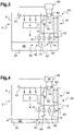
- the picture 3 presents the fluidic system in a nominal operating mode.
- the main fluidic circuit 40 draws the lubricating fluid 26 from the reservoir 25 and routes it into the spray circuit 30.
- the emergency non-return valve 70 is in its closed state.
- the pressure sensor 81 transmits to the alerter 90 a pressure signal carrying a pressure substantially equivalent to the pressure of the lubricating fluid 26 in the main fluidic circuit 40.
- the alerter 90 deduces therefrom that the fluidic system 20 operates normally and no alerts are issued.
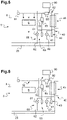
- the fluidic system 20 has a leak qualified as gravity for convenience preventing a return of the lubricating fluid 26 into the reservoir 25.
- the level of the lubricating fluid 26 drops in the reservoir 25. When this level passes below the suction inlet main 42 of the main fluidic circuit 40, the lubricating fluid 26 is no longer in circulation at the within the main fluidic circuit 40.
- the main non-return valve 50 switches to the closed state.
- the emergency non-return valve 70 opens and supplies the spray circuit 30.
- the change of state of the main non-return valve 50 and/or the measurement made by the pressure sensor 81 allow the alerter 90 to detect a malfunction during the aforementioned step STPB.
- the emergency non-return valve 70 being open, following the reception of an emergency state signal emitted by the emergency state sensor 85 carrying this open state of the emergency non-return valve 70, the alerter 90 emits the first alert, for example synonymous with a thirty-minute flight authorization from this moment.
- the lubricating fluid 26 in the reservoir 25 passes below the emergency suction inlet 62 of the emergency fluidic circuit 60, the lubricating fluid 26 is no longer in circulation also within the emergency fluidic circuit 60
- the emergency non-return valve 70 goes into the closed state.
- the alerter 90 emits the second alert, for example synonymous with a fifteen-minute flight authorization from this moment since the elements 6 of the mechanical system are no longer lubricated.
- the fluidic system 20 has a leak at the level of the main fluidic circuit 40 and outside the mechanical system 5.
- the level of the lubricating fluid 26 drops in the reservoir 25. The operation described above also applies in this case.
- the fluidic system 20 has a leak at the level of the spray circuit 30. Consequently, the emergency non-return valve 70 opens.
- the alerter 90 In the presence of a monitoring parameter of the pressure type measured by the pressure sensor 81, the alerter 90 then emits the first alert. In the presence of a carrier-type monitoring parameter of the open or closed state of the main non-return valve 50, the first alert is issued when the level of lubricating fluid 26 in the reservoir 25 falls below the inlet of main suction 42 of the main fluidic circuit 40.
- the lubricating fluid 26 in the reservoir 25 passes below the emergency suction inlet 62 of the emergency fluidic circuit 60, the lubricating fluid 26 is no longer in circulation also within the emergency fluidic circuit 60
- the emergency non-return valve 70 goes into the closed state.
- the alerter 90 emits the second alert, for example synonymous with a fifteen-minute flight authorization from this moment since the elements 6 of the mechanical system are no longer lubricated via the spray circuit 30.
Landscapes
- Engineering & Computer Science (AREA)
- General Engineering & Computer Science (AREA)
- Mechanical Engineering (AREA)
- Chemical & Material Sciences (AREA)
- Oil, Petroleum & Natural Gas (AREA)
- Combustion & Propulsion (AREA)
- Fluid-Pressure Circuits (AREA)
- Testing Of Devices, Machine Parts, Or Other Structures Thereof (AREA)
- Manufacturing & Machinery (AREA)
- Transportation (AREA)
- Aviation & Aerospace Engineering (AREA)
Claims (15)
- Verfahren zur Überwachung eines Fluidsystems (20) zur Schmie rung eines mechanischen Systems (5), wobei das Fluidsystem (20) einen ein Schmierfluid (26) enthaltenden Behälter (25) im Inneren eines Gehäuses (8) des mechanischen Systems (5) umfasst, das Fluidsystem (20) einen Sprühkreislauf (30) mit mindestens einem Sprühkopf (33) umfasst, wobei das Fluidsystem (20) einen Hauptfluidkreislauf (40) umfasst, der sich vom Behälter (25) bis zum Sprühkreislauf (30) erstreckt, das Fluidsystem (20) einen Notfluidkreislauf (60) umfasst, der sich ausgehend vom Tank (25) erstreckt und den Sprühkreis (30) erreicht, wobei der Notfluidkreislauf (60) ein Notrückschlagventil (70) umfasst, das konfiguriert ist, um entweder in einem geschlossenen Zustand, der eine Zirkulation des Schmierfluids (26) unterbindet, oder in einem offenen Zustand zu sein, der einen Durchgang des Schmierfluids (26) vom Tank (25) zum Sprühkreis (30) ermöglicht, wobei der Notfluidkreislauf (60) so dimensioniert ist, dass sich das Notrückschlagventil (70) in einem nominellen Betriebsmodus im geschlossenen Zustand befindet, wobei das Verfahren eine Überwachungsphase (STPB) mit den folgenden Schritten umfasst:- Erfassung einer Störung (STPB 11) durch Überwachen mindestens eines Überwachungsparameters, wobei die Störung den Hauptfluidkreislauf (40) funktionsunfähig macht,- Erfassung (STPB 12), dass sich das Not-Rückschlagventil (70) in dem offenen Zustand oder dem geschlossenen Zustand befindet,dadurch gekennzeichnet, dass die Überwachungsphase (STPB) die folgenden Schritte umfasst:- Erzeugung (STPB21) eines ersten Warnhinweises bei Vorliegen einer Erfassung einer Störung und einer Erfassung, dass sich das Notrückschlagventil (70) in dem offenen Zustand befindet,- Erzeugung (STPB22) eines von dem ersten Warnhinweis verschiedenen zweiten Warnhinweises bei Vorliegen einer Erfassung einer Störung und einer Erfassung, dass sich das Notrückschlagventil (70) in dem geschlossenen Zustand befindet.
- Verfahren nach Anspruch 1,
dadurch gekennzeichnet, dass der mindestens eine Überwachungsparameter ein in dem Sprühkreis (30) herrschender Druck ist, wobei die Erkennung einer Störung durch Überwachung des mindestens einen Überwachungsparameters einen Schritt der Erkennung mit einem Drucksensor (81) umfasst, dass der Druck unter einem vorgegebenen Druckschwellenwert liegt. - Verfahren nach Anspruch 1,
dadurch gekennzeichnet, dass der Hauptfluidkreislauf (40) ein Hauptrückschlagventil (50) umfasst, das konfiguriert ist, um entweder in einem geschlossenen Zustand oder in einem offenen Zustand zu sein, der einen Durchgang des Schmierfluids (26) von dem Reservoir (25) zu dem Sprühkreislauf (30) ermöglicht, wobei der mindestens eine Überwachungsparameter Träger des offenen oder geschlossenen Zustands des Hauptrückschlagventils (50) ist, wobei die Erkennung einer Störung durch Überwachung mindestens eines Überwachungsparameters einen Schritt der Erkennung umfasst, dass sich das Hauptrückschlagventil (50) im geschlossenen Zustand befindet. - Verfahren nach einem der Ansprüche 1 bis 3,
dadurch gekennzeichnet, dass das Verfahren einen Schritt der Erfassung (STPA) umfasst, dass das mechanische System (5) in Betrieb ist, wobei die Überwachungsphase (STPB) durchgeführt wird, wenn das mechanische System (5) in Betrieb ist. - Verfahren nach einem der Ansprüche 1 bis 4,
dadurch gekennzeichnet, dass das mechanische System (5) in einem Luftfahrzeug (2) angeordnet ist, der erste Warnhinweis eine Flugfreigabe für eine erste Zeitdauer beinhaltet und der zweite Warnhinweis eine Flugfreigabe für eine zweite Zeitdauer beinhaltet, die kürzer als die erste Zeitdauer ist. - Fluidsystem (20) mit einem ein Schmierfluid (26) enthaltenden Tank (25) innerhalb eines Gehäuses (8) des mechanischen Systems (5), wobei das Fluidsystem (20) einen Sprühkreis (30) umfasst, wobei das Fluidsystem (20) einen Hauptfluidkreis (40) umfasst, der sich vom Tank zum mit mindestens einem Sprühkopf (33) versehenen Sprühkreis (30) erstreckt, das Fluidsystem (20) einen Notfluidkreislauf (60) umfasst, der sich ausgehend vom Tank (25) erstreckt und den Sprühkreis (30) erreicht, der Notfluidkreislauf (60) ein Notrückschlagventil (70) umfasst, das konfiguriert ist, um entweder in einem geschlossenen Zustand, der eine Zirkulation des Schmierfluids (26) unterbindet, oder in einem offenen Zustand zu sein, der einen Durchgang des Schmierfluids (26) vom Tank (25) zum Sprühkreis (30) ermöglicht, wobei der Notfluidkreislauf (60) so dimensioniert ist, dass sich das Not-rückschlagventil (70) in einem nominellen Betriebsmodus im geschlossenen Zustand befindet, wobei das Fluidsystem (20) mindestens einen Störungssensor (80) umfasst, um die Erfassung einer Störung nach Anspruch 1 durchzuführen, das Fluidsystem (20) einen Notfallsensor (85) aufweist, der konfiguriert ist, um die Erfassung zu bewirken, dass sich das Notrückschlagventil (70) in dem offenen Zustand oder dem geschlossenen Zustand befindet, wobei das Fluidsystem (20) einen Warnmelder (90) aufweist, der mit dem Notfallsensor (85) und dem Störungssensor (80) in Verbindung steht,
dadurch gekennzeichnet, dass das Fluidsystem (20) konfiguriert ist, um das Verfahren nach einem der Ansprüche 1 bis 5 anzuwenden, wobei der Warnmelder (90) konfiguriert ist, um die Erzeugung des ersten Warnhinweises und die Erzeugung des zweiten Warnhinweises durchzuführen. - Fluidsystem (20) nach Anspruch 6,
dadurch gekennzeichnet, dass der Störungssensor (80) einen Drucksensor (81) umfasst, der ein Drucksignal ausgibt, das sich in Abhängigkeit von einem in dem Sprühkreis (30) herrschenden Druck ändert, wobei das Drucksignal an den Warnmelder (90) übermittelt wird. - Fluidsystem (20) nach einem der Ansprüche 6 bis 7,
dadurch gekennzeichnet, dass der Hauptfluidkreislauf (40) ein Hauptrückschlagventil (50) umfasst, das konfiguriert ist, um entweder in einem geschlossenen Zustand oder in einem offenen Zustand zu sein, der einen Durchgang des Schmierfluids (26) von dem Reservoir (25) zu dem Sprühkreislauf (30) ermöglicht, wobei der Störungssensor (80) einen Hauptzustandssensor (82) umfasst, der konfiguriert ist, um eine Erfassung durchzuführen, dass das Hauptrückschlagventil (50) in dem offenen Zustand oder in dem geschlossenen Zustand ist. - Fluidsystem (20) nach einem der Ansprüche 6 bis 8,
dadurch gekennzeichnet, dass das Fluidsystem (20) einen Betriebssensor (95) aufweist, um zu erfassen, ob das mechanische System (5) in Betrieb ist. - Baugruppe (4) mit einem mechanischen System (5), das mindestens ein zu schmierendes Element (6) und ein Fluidsystem (20) zum Schmieren des mindestens einen zu schmierenden Elements (6) aufweist,
dadurch gekennzeichnet, dass das Fluidsystem (20) gemäß einem der Ansprüche 6 bis 9 ist. - Baugruppe nach Anspruch 10,
dadurch gekennzeichnet, dass das mechanische System (5) ein Kraftübertragungsgetriebe (7) ist. - Baugruppe nach einem der Ansprüche 10 bis 11,
dadurch gekennzeichnet, dass sich der Sprühkreislauf (30) teilweise innerhalb des mechanischen Systems (5) und teilweise außerhalb des mechanischen Systems (5) erstreckt. - Baugruppe nach einem der Ansprüche 10 bis 12,
dadurch gekennzeichnet, dass das Notrückschlagventil (70) in den Sprühkreis (30) mündet. - Verkehrsmittel (1) mit einer Baugruppe (4),
dadurch gekennzeichnet, dass die Baugruppe (4) nach einem der Ansprüche 10 bis 13 ist. - Verkehrsmittel nach Anspruch 14,
dadurch gekennzeichnet, dass das Verkehrsmittel (1) ein Drehflügelflugzeug (2) mit einem durch das mechanische System (5) in Drehung versetzten Rotor (3) ist.
Applications Claiming Priority (1)
| Application Number | Priority Date | Filing Date | Title |
|---|---|---|---|
| FR2007657A FR3112835B1 (fr) | 2020-07-21 | 2020-07-21 | Procédé de surveillance d’un système fluidique lubrifiant un système mécanique |
Publications (2)
| Publication Number | Publication Date |
|---|---|
| EP3943783A1 EP3943783A1 (de) | 2022-01-26 |
| EP3943783B1 true EP3943783B1 (de) | 2022-11-16 |
Family
ID=73013621
Family Applications (1)
| Application Number | Title | Priority Date | Filing Date |
|---|---|---|---|
| EP21174432.1A Active EP3943783B1 (de) | 2020-07-21 | 2021-05-18 | Verfahren zur überwachung eines flüssigkeitssystems zur schmierung eines mechanischen systems |
Country Status (3)
| Country | Link |
|---|---|
| US (1) | US12013082B2 (de) |
| EP (1) | EP3943783B1 (de) |
| FR (1) | FR3112835B1 (de) |
Families Citing this family (5)
| Publication number | Priority date | Publication date | Assignee | Title |
|---|---|---|---|---|
| US11668289B2 (en) | 2021-05-12 | 2023-06-06 | Yantai Jereh Petroleum Equipment & Technologies Co., Ltd. | Fracturing apparatus |
| US12442370B2 (en) | 2021-04-07 | 2025-10-14 | Yantai Jereh Petroleum Equipment & Technologies Co., Ltd. | Fracturing equipment having multiple electric-power supplies |
| CN114985472A (zh) * | 2022-05-23 | 2022-09-02 | 首钢京唐钢铁联合有限责任公司 | 轧机润滑系统的控制方法及相关设备 |
| FR3139196B1 (fr) | 2022-08-31 | 2024-07-26 | Airbus Helicopters | Procede de surveillance d’un systeme fluidique lubrifiant un systeme mecanique |
| CN115556964B (zh) * | 2022-11-21 | 2023-03-10 | 中国飞机强度研究所 | 用于飞机测试的喷雾试验供气装置及供气方法 |
Family Cites Families (17)
| Publication number | Priority date | Publication date | Assignee | Title |
|---|---|---|---|---|
| US4520902A (en) * | 1983-04-19 | 1985-06-04 | Lubriquip-Houdaille, Inc. | Lubricant applying system and injector means |
| US4674030A (en) * | 1984-01-24 | 1987-06-16 | Bijur Lubricating Corp. | Lubricating system control circuit |
| US5239861A (en) * | 1988-12-23 | 1993-08-31 | Kabushiki Kaisha Komatsu Seisakusho | Device for indicating contamination degree of hydraulic circuit and method of judging the contamination degree |
| IT1232583B (it) * | 1989-02-14 | 1992-02-26 | Fiat Aviazione | Impianto di lubrificazione di organi meccanici particolarmente di impigo aeronautico provvisto di un dispositivo di emergenza atto a garantire una fornitura minima di olio lubrificante |
| FR2658577A1 (fr) | 1990-02-20 | 1991-08-23 | Aerospatiale | Dispositif de lubrification de secours pour reducteur notamment pour boite de transmission principale de giravion. |
| FR2685758B1 (fr) | 1991-12-26 | 1995-03-31 | Aerospatiale | Systeme de lubrification et de refroidissement de secours d'un multiplicateur/reducteur mecanique du type "boite de transmission" d'helicoptere en cas de defaillance du circuit de lubrification. |
| FR2826094B1 (fr) | 2001-06-15 | 2003-11-28 | Eurocopter France | Systeme de lubrification et de refroidissement d'un ensemble mecanique |
| FR2831938B1 (fr) * | 2001-11-07 | 2004-02-20 | Eurocopter France | Installation de lubrification pour boite de transmission de puissance basculante |
| DE102013224017A1 (de) * | 2013-11-25 | 2015-05-28 | Zf Friedrichshafen Ag | Notschmierung für Windkraftgetriebe |
| US10072521B2 (en) * | 2013-12-05 | 2018-09-11 | United Technologies Corporation | FDGS auxiliary pump monitoring system |
| US10145276B2 (en) * | 2015-06-23 | 2018-12-04 | United Technologies Corporation | Lubricant valve monitoring method and assembly |
| FR3045764B1 (fr) | 2015-12-17 | 2017-12-22 | Airbus Helicopters | Dispositif de lubrification de secours a architecture simplifiee pour une boite de transmission principale de puissance d'un aeronef |
| US10190672B2 (en) * | 2016-04-04 | 2019-01-29 | Bell Helicopter Textron Inc. | Gearbox lubrication system |
| FR3068006B1 (fr) * | 2017-06-23 | 2020-05-22 | Airbus Helicopters | Systeme de recuperation d'energie thermique d'une boite de tranmission principale de puissance d'un aeronef pour le chauffage l'habitacle de l'aeronef |
| US11480027B2 (en) * | 2017-12-14 | 2022-10-25 | Downing Wellhead Equipment, Llc | Intelligently controlled fluid systems |
| US10711877B2 (en) * | 2018-02-23 | 2020-07-14 | General Electric Company | Passive lubrication system for gas turbine engine gearbox during wind milling |
| CN111076072A (zh) * | 2019-12-30 | 2020-04-28 | 中国船舶重工集团公司第七一一研究所 | 柴油机气阀和阀座之间加油润滑装置 |
-
2020
- 2020-07-21 FR FR2007657A patent/FR3112835B1/fr not_active Expired - Fee Related
-
2021
- 2021-05-18 EP EP21174432.1A patent/EP3943783B1/de active Active
- 2021-06-17 US US17/350,638 patent/US12013082B2/en active Active
Also Published As
| Publication number | Publication date |
|---|---|
| EP3943783A1 (de) | 2022-01-26 |
| FR3112835A1 (fr) | 2022-01-28 |
| FR3112835B1 (fr) | 2022-06-24 |
| US12013082B2 (en) | 2024-06-18 |
| US20220026020A1 (en) | 2022-01-27 |
Similar Documents
| Publication | Publication Date | Title |
|---|---|---|
| EP3943783A1 (de) | Verfahren zur überwachung eines flüssigkeitssystems zur schmierung eines mechanischen systems | |
| EP3015743B1 (de) | Schmierverfahren und -vorrichtung mit verbesserter zuverlässigkeit mit dreifachkreislauf eines hauptleistungsübertragungsgetriebes eines luftfahrzeugs | |
| EP3021030B1 (de) | Schmierverfahren und -vorrichtung mit verbesserter zuverlässigkeit mit doppelkreislauf eines hauptleistungsübertragungsgetriebes eines luftfahrzeugs | |
| EP3181951B1 (de) | Not-schmiervorrichtung mit vereinfachtem aufbau für ein hauptleistungsübertragungsgetriebe eines luftfahrzeugs | |
| CN105829681B (zh) | 用于航空器发动机的流体排出设备 | |
| EP3104044B1 (de) | Leistungsübertragungsgetriebe und luftfahrzeug | |
| EP2979980B1 (de) | Verfahren und vorrichtung zum erfassen, ob ein flugzeug in vereisungskonditionen fliegt | |
| EP4284685B1 (de) | Verfahren zur funktionsüberprüfung eines fahrzeugoberflächenreinigungsgerätes | |
| CN112334683B (zh) | 飞行器涡轮发动机的组件及其控制方法,飞行器涡轮发动机 | |
| FR3068757A1 (fr) | Dispositif d'etancheite pour arbre de propulsion d'une unite de propulsion de vehicule marin | |
| EP4257866B1 (de) | Mechanisches system mit einem gehäuse, das über schmier- oder kühlelemente eines tanks eines schmierenden fluidsystems untergebracht ist | |
| FR3088956A1 (fr) | Systeme de lubrification pour turbomachine d’aeronef, comprenant des moyens ameliores de detection de fuite | |
| EP4331980B1 (de) | Verfahren zur überwachung eines schmierenden fluidsystems eines mechanischen systems | |
| FR2500578A1 (fr) | Buse a double fonction pour lubrification de secours par brouillard d'huile | |
| EP3978784A1 (de) | Schmiersystem mit einem ersatzbehälter | |
| FR3020093A1 (fr) | Dispositif de stockage de lubrifiant pour un circuit de lubrification d'un moteur d'aeronef | |
| EP4232325B1 (de) | Reinigungssystem für ein kraftfahrzeug | |
| FR3147604A1 (fr) | Système d’actionnement hydraulique à réchauffeur intégré et aéronef le comprenant. | |
| FR3083283A1 (fr) | Systeme de lubrification pour une boite de transmission principale de puissance d 'un aeronef avec une dispositif ameliore de captation et de detection des particules metalliques | |
| BE1025462B1 (fr) | Détermination d'un colmatage d'un filtre d'un système hydraulique | |
| EP4556325B1 (de) | Aktuator mit zwei drucksensoren und einem virtuellen drucksensor; bremssystem und luftfahrzeug mit einem solchen aktuator und verfahren zur anwendung dieses stellglieds | |
| EP1681470A1 (de) | Feuerlöschkreiselpumpe mit Vorrichtung zur Kavitationsdetektion | |
| FR3100189A1 (fr) | Système hydraulique et procédé associé pour la détection d’une fuite dans la conduite de commande | |
| EP3366890B1 (de) | Integriertes schmiersystem | |
| FR3159215A1 (fr) | Système mécanique muni d’éléments mécaniques mobiles, d’un bouchon magnétique ainsi que d’un système de lubrification muni de filtres mécanique et magnétique. |
Legal Events
| Date | Code | Title | Description |
|---|---|---|---|
| PUAI | Public reference made under article 153(3) epc to a published international application that has entered the european phase |
Free format text: ORIGINAL CODE: 0009012 |
|
| STAA | Information on the status of an ep patent application or granted ep patent |
Free format text: STATUS: THE APPLICATION HAS BEEN PUBLISHED |
|
| AK | Designated contracting states |
Kind code of ref document: A1 Designated state(s): AL AT BE BG CH CY CZ DE DK EE ES FI FR GB GR HR HU IE IS IT LI LT LU LV MC MK MT NL NO PL PT RO RS SE SI SK SM TR |
|
| STAA | Information on the status of an ep patent application or granted ep patent |
Free format text: STATUS: REQUEST FOR EXAMINATION WAS MADE |
|
| 17P | Request for examination filed |
Effective date: 20220223 |
|
| RBV | Designated contracting states (corrected) |
Designated state(s): AL AT BE BG CH CY CZ DE DK EE ES FI FR GB GR HR HU IE IS IT LI LT LU LV MC MK MT NL NO PL PT RO RS SE SI SK SM TR |
|
| GRAP | Despatch of communication of intention to grant a patent |
Free format text: ORIGINAL CODE: EPIDOSNIGR1 |
|
| STAA | Information on the status of an ep patent application or granted ep patent |
Free format text: STATUS: GRANT OF PATENT IS INTENDED |
|
| RIC1 | Information provided on ipc code assigned before grant |
Ipc: B64D 35/00 20060101ALN20220621BHEP Ipc: B64C 27/12 20060101ALN20220621BHEP Ipc: B64C 27/04 20060101ALN20220621BHEP Ipc: F16N 29/04 20060101ALI20220621BHEP Ipc: F16N 7/32 20060101ALI20220621BHEP Ipc: F16N 29/02 20060101ALI20220621BHEP Ipc: F16H 57/04 20100101AFI20220621BHEP |
|
| INTG | Intention to grant announced |
Effective date: 20220714 |
|
| GRAS | Grant fee paid |
Free format text: ORIGINAL CODE: EPIDOSNIGR3 |
|
| GRAA | (expected) grant |
Free format text: ORIGINAL CODE: 0009210 |
|
| STAA | Information on the status of an ep patent application or granted ep patent |
Free format text: STATUS: THE PATENT HAS BEEN GRANTED |
|
| AK | Designated contracting states |
Kind code of ref document: B1 Designated state(s): AL AT BE BG CH CY CZ DE DK EE ES FI FR GB GR HR HU IE IS IT LI LT LU LV MC MK MT NL NO PL PT RO RS SE SI SK SM TR |
|
| REG | Reference to a national code |
Ref country code: GB Ref legal event code: FG4D Free format text: NOT ENGLISH |
|
| REG | Reference to a national code |
Ref country code: CH Ref legal event code: EP |
|
| REG | Reference to a national code |
Ref country code: IE Ref legal event code: FG4D Free format text: LANGUAGE OF EP DOCUMENT: FRENCH |
|
| REG | Reference to a national code |
Ref country code: DE Ref legal event code: R096 Ref document number: 602021000769 Country of ref document: DE |
|
| REG | Reference to a national code |
Ref country code: AT Ref legal event code: REF Ref document number: 1531944 Country of ref document: AT Kind code of ref document: T Effective date: 20221215 |
|
| REG | Reference to a national code |
Ref country code: LT Ref legal event code: MG9D |
|
| REG | Reference to a national code |
Ref country code: NL Ref legal event code: MP Effective date: 20221116 |
|
| REG | Reference to a national code |
Ref country code: AT Ref legal event code: MK05 Ref document number: 1531944 Country of ref document: AT Kind code of ref document: T Effective date: 20221116 |
|
| PG25 | Lapsed in a contracting state [announced via postgrant information from national office to epo] |
Ref country code: SE Free format text: LAPSE BECAUSE OF FAILURE TO SUBMIT A TRANSLATION OF THE DESCRIPTION OR TO PAY THE FEE WITHIN THE PRESCRIBED TIME-LIMIT Effective date: 20221116 Ref country code: PT Free format text: LAPSE BECAUSE OF FAILURE TO SUBMIT A TRANSLATION OF THE DESCRIPTION OR TO PAY THE FEE WITHIN THE PRESCRIBED TIME-LIMIT Effective date: 20230316 Ref country code: NO Free format text: LAPSE BECAUSE OF FAILURE TO SUBMIT A TRANSLATION OF THE DESCRIPTION OR TO PAY THE FEE WITHIN THE PRESCRIBED TIME-LIMIT Effective date: 20230216 Ref country code: LT Free format text: LAPSE BECAUSE OF FAILURE TO SUBMIT A TRANSLATION OF THE DESCRIPTION OR TO PAY THE FEE WITHIN THE PRESCRIBED TIME-LIMIT Effective date: 20221116 Ref country code: FI Free format text: LAPSE BECAUSE OF FAILURE TO SUBMIT A TRANSLATION OF THE DESCRIPTION OR TO PAY THE FEE WITHIN THE PRESCRIBED TIME-LIMIT Effective date: 20221116 Ref country code: ES Free format text: LAPSE BECAUSE OF FAILURE TO SUBMIT A TRANSLATION OF THE DESCRIPTION OR TO PAY THE FEE WITHIN THE PRESCRIBED TIME-LIMIT Effective date: 20221116 Ref country code: AT Free format text: LAPSE BECAUSE OF FAILURE TO SUBMIT A TRANSLATION OF THE DESCRIPTION OR TO PAY THE FEE WITHIN THE PRESCRIBED TIME-LIMIT Effective date: 20221116 |
|
| PG25 | Lapsed in a contracting state [announced via postgrant information from national office to epo] |
Ref country code: RS Free format text: LAPSE BECAUSE OF FAILURE TO SUBMIT A TRANSLATION OF THE DESCRIPTION OR TO PAY THE FEE WITHIN THE PRESCRIBED TIME-LIMIT Effective date: 20221116 Ref country code: PL Free format text: LAPSE BECAUSE OF FAILURE TO SUBMIT A TRANSLATION OF THE DESCRIPTION OR TO PAY THE FEE WITHIN THE PRESCRIBED TIME-LIMIT Effective date: 20221116 Ref country code: LV Free format text: LAPSE BECAUSE OF FAILURE TO SUBMIT A TRANSLATION OF THE DESCRIPTION OR TO PAY THE FEE WITHIN THE PRESCRIBED TIME-LIMIT Effective date: 20221116 Ref country code: IS Free format text: LAPSE BECAUSE OF FAILURE TO SUBMIT A TRANSLATION OF THE DESCRIPTION OR TO PAY THE FEE WITHIN THE PRESCRIBED TIME-LIMIT Effective date: 20230316 Ref country code: HR Free format text: LAPSE BECAUSE OF FAILURE TO SUBMIT A TRANSLATION OF THE DESCRIPTION OR TO PAY THE FEE WITHIN THE PRESCRIBED TIME-LIMIT Effective date: 20221116 Ref country code: GR Free format text: LAPSE BECAUSE OF FAILURE TO SUBMIT A TRANSLATION OF THE DESCRIPTION OR TO PAY THE FEE WITHIN THE PRESCRIBED TIME-LIMIT Effective date: 20230217 |
|
| PG25 | Lapsed in a contracting state [announced via postgrant information from national office to epo] |
Ref country code: NL Free format text: LAPSE BECAUSE OF FAILURE TO SUBMIT A TRANSLATION OF THE DESCRIPTION OR TO PAY THE FEE WITHIN THE PRESCRIBED TIME-LIMIT Effective date: 20221116 |
|
| P01 | Opt-out of the competence of the unified patent court (upc) registered |
Effective date: 20230530 |
|
| PG25 | Lapsed in a contracting state [announced via postgrant information from national office to epo] |
Ref country code: SM Free format text: LAPSE BECAUSE OF FAILURE TO SUBMIT A TRANSLATION OF THE DESCRIPTION OR TO PAY THE FEE WITHIN THE PRESCRIBED TIME-LIMIT Effective date: 20221116 Ref country code: RO Free format text: LAPSE BECAUSE OF FAILURE TO SUBMIT A TRANSLATION OF THE DESCRIPTION OR TO PAY THE FEE WITHIN THE PRESCRIBED TIME-LIMIT Effective date: 20221116 Ref country code: EE Free format text: LAPSE BECAUSE OF FAILURE TO SUBMIT A TRANSLATION OF THE DESCRIPTION OR TO PAY THE FEE WITHIN THE PRESCRIBED TIME-LIMIT Effective date: 20221116 Ref country code: DK Free format text: LAPSE BECAUSE OF FAILURE TO SUBMIT A TRANSLATION OF THE DESCRIPTION OR TO PAY THE FEE WITHIN THE PRESCRIBED TIME-LIMIT Effective date: 20221116 Ref country code: CZ Free format text: LAPSE BECAUSE OF FAILURE TO SUBMIT A TRANSLATION OF THE DESCRIPTION OR TO PAY THE FEE WITHIN THE PRESCRIBED TIME-LIMIT Effective date: 20221116 |
|
| REG | Reference to a national code |
Ref country code: DE Ref legal event code: R097 Ref document number: 602021000769 Country of ref document: DE |
|
| PG25 | Lapsed in a contracting state [announced via postgrant information from national office to epo] |
Ref country code: SK Free format text: LAPSE BECAUSE OF FAILURE TO SUBMIT A TRANSLATION OF THE DESCRIPTION OR TO PAY THE FEE WITHIN THE PRESCRIBED TIME-LIMIT Effective date: 20221116 Ref country code: AL Free format text: LAPSE BECAUSE OF FAILURE TO SUBMIT A TRANSLATION OF THE DESCRIPTION OR TO PAY THE FEE WITHIN THE PRESCRIBED TIME-LIMIT Effective date: 20221116 |
|
| PLBE | No opposition filed within time limit |
Free format text: ORIGINAL CODE: 0009261 |
|
| STAA | Information on the status of an ep patent application or granted ep patent |
Free format text: STATUS: NO OPPOSITION FILED WITHIN TIME LIMIT |
|
| 26N | No opposition filed |
Effective date: 20230817 |
|
| PG25 | Lapsed in a contracting state [announced via postgrant information from national office to epo] |
Ref country code: SI Free format text: LAPSE BECAUSE OF FAILURE TO SUBMIT A TRANSLATION OF THE DESCRIPTION OR TO PAY THE FEE WITHIN THE PRESCRIBED TIME-LIMIT Effective date: 20221116 |
|
| REG | Reference to a national code |
Ref country code: DE Ref legal event code: R119 Ref document number: 602021000769 Country of ref document: DE |
|
| PG25 | Lapsed in a contracting state [announced via postgrant information from national office to epo] |
Ref country code: MC Free format text: LAPSE BECAUSE OF FAILURE TO SUBMIT A TRANSLATION OF THE DESCRIPTION OR TO PAY THE FEE WITHIN THE PRESCRIBED TIME-LIMIT Effective date: 20221116 |
|
| REG | Reference to a national code |
Ref country code: BE Ref legal event code: MM Effective date: 20230531 |
|
| PG25 | Lapsed in a contracting state [announced via postgrant information from national office to epo] |
Ref country code: MC Free format text: LAPSE BECAUSE OF FAILURE TO SUBMIT A TRANSLATION OF THE DESCRIPTION OR TO PAY THE FEE WITHIN THE PRESCRIBED TIME-LIMIT Effective date: 20221116 Ref country code: LU Free format text: LAPSE BECAUSE OF NON-PAYMENT OF DUE FEES Effective date: 20230518 |
|
| REG | Reference to a national code |
Ref country code: IE Ref legal event code: MM4A |
|
| PG25 | Lapsed in a contracting state [announced via postgrant information from national office to epo] |
Ref country code: IE Free format text: LAPSE BECAUSE OF NON-PAYMENT OF DUE FEES Effective date: 20230518 |
|
| PG25 | Lapsed in a contracting state [announced via postgrant information from national office to epo] |
Ref country code: IE Free format text: LAPSE BECAUSE OF NON-PAYMENT OF DUE FEES Effective date: 20230518 Ref country code: DE Free format text: LAPSE BECAUSE OF NON-PAYMENT OF DUE FEES Effective date: 20231201 |
|
| PG25 | Lapsed in a contracting state [announced via postgrant information from national office to epo] |
Ref country code: BE Free format text: LAPSE BECAUSE OF NON-PAYMENT OF DUE FEES Effective date: 20230531 |
|
| PG25 | Lapsed in a contracting state [announced via postgrant information from national office to epo] |
Ref country code: BG Free format text: LAPSE BECAUSE OF FAILURE TO SUBMIT A TRANSLATION OF THE DESCRIPTION OR TO PAY THE FEE WITHIN THE PRESCRIBED TIME-LIMIT Effective date: 20221116 |
|
| PG25 | Lapsed in a contracting state [announced via postgrant information from national office to epo] |
Ref country code: BG Free format text: LAPSE BECAUSE OF FAILURE TO SUBMIT A TRANSLATION OF THE DESCRIPTION OR TO PAY THE FEE WITHIN THE PRESCRIBED TIME-LIMIT Effective date: 20221116 |
|
| REG | Reference to a national code |
Ref country code: CH Ref legal event code: PL |
|
| PG25 | Lapsed in a contracting state [announced via postgrant information from national office to epo] |
Ref country code: CH Free format text: LAPSE BECAUSE OF NON-PAYMENT OF DUE FEES Effective date: 20240531 |
|
| PGFP | Annual fee paid to national office [announced via postgrant information from national office to epo] |
Ref country code: GB Payment date: 20250527 Year of fee payment: 5 |
|
| PGFP | Annual fee paid to national office [announced via postgrant information from national office to epo] |
Ref country code: IT Payment date: 20250527 Year of fee payment: 5 |
|
| PGFP | Annual fee paid to national office [announced via postgrant information from national office to epo] |
Ref country code: FR Payment date: 20250528 Year of fee payment: 5 |
|
| PG25 | Lapsed in a contracting state [announced via postgrant information from national office to epo] |
Ref country code: CY Free format text: LAPSE BECAUSE OF FAILURE TO SUBMIT A TRANSLATION OF THE DESCRIPTION OR TO PAY THE FEE WITHIN THE PRESCRIBED TIME-LIMIT; INVALID AB INITIO Effective date: 20210518 |
|
| PG25 | Lapsed in a contracting state [announced via postgrant information from national office to epo] |
Ref country code: HU Free format text: LAPSE BECAUSE OF FAILURE TO SUBMIT A TRANSLATION OF THE DESCRIPTION OR TO PAY THE FEE WITHIN THE PRESCRIBED TIME-LIMIT; INVALID AB INITIO Effective date: 20210518 |
|
| PG25 | Lapsed in a contracting state [announced via postgrant information from national office to epo] |
Ref country code: TR Free format text: LAPSE BECAUSE OF FAILURE TO SUBMIT A TRANSLATION OF THE DESCRIPTION OR TO PAY THE FEE WITHIN THE PRESCRIBED TIME-LIMIT Effective date: 20221116 |