EP4331980B1 - Verfahren zur überwachung eines schmierenden fluidsystems eines mechanischen systems - Google Patents
Verfahren zur überwachung eines schmierenden fluidsystems eines mechanischen systems Download PDFInfo
- Publication number
- EP4331980B1 EP4331980B1 EP23175907.7A EP23175907A EP4331980B1 EP 4331980 B1 EP4331980 B1 EP 4331980B1 EP 23175907 A EP23175907 A EP 23175907A EP 4331980 B1 EP4331980 B1 EP 4331980B1
- Authority
- EP
- European Patent Office
- Prior art keywords
- fluid
- blocker
- main
- emergency
- circuit
- Prior art date
- Legal status (The legal status is an assumption and is not a legal conclusion. Google has not performed a legal analysis and makes no representation as to the accuracy of the status listed.)
- Active
Links
Images


Classifications
-
- G—PHYSICS
- G01—MEASURING; TESTING
- G01M—TESTING STATIC OR DYNAMIC BALANCE OF MACHINES OR STRUCTURES; TESTING OF STRUCTURES OR APPARATUS, NOT OTHERWISE PROVIDED FOR
- G01M13/00—Testing of machine parts
- G01M13/02—Gearings; Transmission mechanisms
-
- B—PERFORMING OPERATIONS; TRANSPORTING
- B64—AIRCRAFT; AVIATION; COSMONAUTICS
- B64C—AEROPLANES; HELICOPTERS
- B64C27/00—Rotorcraft; Rotors peculiar thereto
- B64C27/04—Helicopters
- B64C27/12—Rotor drives
-
- F—MECHANICAL ENGINEERING; LIGHTING; HEATING; WEAPONS; BLASTING
- F16—ENGINEERING ELEMENTS AND UNITS; GENERAL MEASURES FOR PRODUCING AND MAINTAINING EFFECTIVE FUNCTIONING OF MACHINES OR INSTALLATIONS; THERMAL INSULATION IN GENERAL
- F16H—GEARING
- F16H57/00—General details of gearing
- F16H57/04—Features relating to lubrication or cooling or heating
- F16H57/0434—Features relating to lubrication or cooling or heating relating to lubrication supply, e.g. pumps; Pressure control
-
- F—MECHANICAL ENGINEERING; LIGHTING; HEATING; WEAPONS; BLASTING
- F16—ENGINEERING ELEMENTS AND UNITS; GENERAL MEASURES FOR PRODUCING AND MAINTAINING EFFECTIVE FUNCTIONING OF MACHINES OR INSTALLATIONS; THERMAL INSULATION IN GENERAL
- F16H—GEARING
- F16H57/00—General details of gearing
- F16H57/04—Features relating to lubrication or cooling or heating
- F16H57/0434—Features relating to lubrication or cooling or heating relating to lubrication supply, e.g. pumps; Pressure control
- F16H57/0435—Pressure control for supplying lubricant; Circuits or valves therefor
-
- F—MECHANICAL ENGINEERING; LIGHTING; HEATING; WEAPONS; BLASTING
- F16—ENGINEERING ELEMENTS AND UNITS; GENERAL MEASURES FOR PRODUCING AND MAINTAINING EFFECTIVE FUNCTIONING OF MACHINES OR INSTALLATIONS; THERMAL INSULATION IN GENERAL
- F16H—GEARING
- F16H57/00—General details of gearing
- F16H57/04—Features relating to lubrication or cooling or heating
- F16H57/0434—Features relating to lubrication or cooling or heating relating to lubrication supply, e.g. pumps; Pressure control
- F16H57/0442—Features relating to lubrication or cooling or heating relating to lubrication supply, e.g. pumps; Pressure control for supply in case of failure, i.e. auxiliary supply
-
- F—MECHANICAL ENGINEERING; LIGHTING; HEATING; WEAPONS; BLASTING
- F16—ENGINEERING ELEMENTS AND UNITS; GENERAL MEASURES FOR PRODUCING AND MAINTAINING EFFECTIVE FUNCTIONING OF MACHINES OR INSTALLATIONS; THERMAL INSULATION IN GENERAL
- F16N—LUBRICATING
- F16N29/00—Special means in lubricating arrangements or systems providing for the indication or detection of undesired conditions; Use of devices responsive to conditions in lubricating arrangements or systems
- F16N29/04—Special means in lubricating arrangements or systems providing for the indication or detection of undesired conditions; Use of devices responsive to conditions in lubricating arrangements or systems enabling a warning to be given; enabling moving parts to be stopped
-
- F—MECHANICAL ENGINEERING; LIGHTING; HEATING; WEAPONS; BLASTING
- F16—ENGINEERING ELEMENTS AND UNITS; GENERAL MEASURES FOR PRODUCING AND MAINTAINING EFFECTIVE FUNCTIONING OF MACHINES OR INSTALLATIONS; THERMAL INSULATION IN GENERAL
- F16N—LUBRICATING
- F16N7/00—Arrangements for supplying oil or unspecified lubricant from a stationary reservoir or the equivalent in or on the machine or member to be lubricated
- F16N7/30—Arrangements for supplying oil or unspecified lubricant from a stationary reservoir or the equivalent in or on the machine or member to be lubricated the oil being fed or carried along by another fluid
- F16N7/32—Mist lubrication
-
- F—MECHANICAL ENGINEERING; LIGHTING; HEATING; WEAPONS; BLASTING
- F16—ENGINEERING ELEMENTS AND UNITS; GENERAL MEASURES FOR PRODUCING AND MAINTAINING EFFECTIVE FUNCTIONING OF MACHINES OR INSTALLATIONS; THERMAL INSULATION IN GENERAL
- F16N—LUBRICATING
- F16N2210/00—Applications
- F16N2210/08—Aircraft
-
- F—MECHANICAL ENGINEERING; LIGHTING; HEATING; WEAPONS; BLASTING
- F16—ENGINEERING ELEMENTS AND UNITS; GENERAL MEASURES FOR PRODUCING AND MAINTAINING EFFECTIVE FUNCTIONING OF MACHINES OR INSTALLATIONS; THERMAL INSULATION IN GENERAL
- F16N—LUBRICATING
- F16N2210/00—Applications
- F16N2210/12—Gearings
-
- F—MECHANICAL ENGINEERING; LIGHTING; HEATING; WEAPONS; BLASTING
- F16—ENGINEERING ELEMENTS AND UNITS; GENERAL MEASURES FOR PRODUCING AND MAINTAINING EFFECTIVE FUNCTIONING OF MACHINES OR INSTALLATIONS; THERMAL INSULATION IN GENERAL
- F16N—LUBRICATING
- F16N2260/00—Fail safe
- F16N2260/20—Emergency
Definitions
- the present invention relates to a method for monitoring a fluidic system lubricating a mechanical system, and in particular a power transmission box of an aircraft.
- the invention also relates to such a fluidic system, an assembly comprising a mechanical system and the fluidic system, and a vehicle comprising this assembly.
- the present invention relates to the field of lubrication and cooling of mechanical systems and in particular power transmission boxes, or in particular power transmission boxes intended for a rotary wing aircraft.
- a rotary wing aircraft of the rotorcraft type comprises a rotor that participates at least partially in the lift of this aircraft.
- a rotorcraft is equipped with a power plant comprising at least one engine.
- a power transmission box may be interposed between at least one engine and at least one rotor.
- a power transmission box comprises moving elements.
- a fluid system makes it possible, on the one hand, to lubricate contact zones of the moving elements and, on the other hand, to cool them.
- a fluidic system comprises a single fluidic circuit supplying a spray circuit sometimes called a "lubrication rail" or "fluid spray rail".
- the spray circuit comprises a pressure switch and one or more pipes leading to sprinklers of the nozzle type or others.
- a fluid system can therefore comprise a main fluid circuit and a backup fluid circuit.
- the main fluid circuit and the backup fluid circuit are configured to draw oil from the same reservoir and to convey this oil to the same spray circuit.
- the spray circuit comprises sprinklers which spray the oil into the mechanical system at the various locations to be lubricated.
- the reservoir can be arranged in the bottom of this power transmission box so that the oil sprayed by the spray circuit returns to the reservoir by gravity.
- the main fluid circuit comprises a main pump comprising a suction inlet submerged in the reservoir.
- the pump is connected to at least one heat exchanger via a first main hydraulic line.
- the heat exchanger is located outside the mechanical system to be lubricated.
- this heat exchanger is connected to the spray circuit via a second main hydraulic line.
- the second main hydraulic line comprises a main check valve upstream of the spray circuit and a main pressure switch.
- a main discharge line provided with a pressure relief valve may be in fluid communication with the first main hydraulic line and the reservoir.
- the secondary fluid circuit does not have a heat exchanger.
- the secondary fluid circuit includes a secondary pump with a secondary suction inlet drawing oil from deeper in the reservoir than the main pump of the main fluid circuit.
- the secondary pump is connected to a secondary hydraulic line leading to the spray circuit downstream of the second main hydraulic line and outside the mechanical system to be lubricated.
- the secondary hydraulic line includes a emergency check valve upstream of the sprinkler circuit and a secondary pressure switch.
- a secondary discharge line equipped with a pressure relief valve may be in fluid communication with the secondary hydraulic line and the tank.
- the primary and secondary pumps are sized so that the emergency check valve is closed in a nominal operating mode.
- the main pump draws oil from the reservoir via its suction inlet and then propels it into the first main hydraulic line.
- This oil is cooled in the heat exchanger(s) and then conveyed to the sprinklers.
- the sprinklers then spray the oil, directing it onto the moving parts to cool and lubricate them.
- the oil then falls back by gravity into the reservoir.
- the secondary pump also draws oil from the reservoir. However, the emergency check valve is closed by the pressure of the oil from the main fluid circuit. The oil drawn by the secondary pump then returns to the reservoir via the secondary discharge line.
- the operation of the fluid system is monitored using various pressure switches.
- Such a fluidic system is interesting in that it allows the reservoir and the spray circuit to be shared.
- the document FR 2685758 describes a power transmission box having a fluid system that is provided with a backup fluid circuit independent of a main fluid circuit.
- This backup fluid circuit has its own reservoir for supplying a backup nozzle via an actuator.
- This actuator may comprise a valve or a pump cooperating with an oil pressure sensor disposed in the main fluid circuit or with a temperature sensor disposed on a casing of the power transmission box.
- the document FR 2826094 also describes an alternative system equipped with a pressure sensor measuring pressure within the main fluid circuit.
- the document FR 2658577 describes a fluid system provided with a main fluid circuit having a main reservoir and a backup fluid circuit provided with a bypass conduit.
- the conduit bypass is connected to the main fluid circuit and opens into a backup tank.
- the backup tank has an overflow connected to the main tank of the main fluid circuit and has a low-flow oil distribution circuit.
- the document FR 3045764 describes a fluid system having a main fluid circuit having a main reservoir and a backup fluid circuit having a secondary reservoir.
- the document US 2016/376949 A1 describes a method for determining whether a valve is in a primary position or a secondary position.
- the present invention therefore aims to propose an innovative method and fluidic system for lubricating a mechanical system, the fluidic system being provided with a main fluidic circuit and a backup fluidic circuit cooperating with the same spray circuit and aiming to identify and estimate the current operating mode of the fluidic system.
- the invention thus relates to a method for monitoring a fluid lubrication system of a mechanical system.
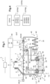
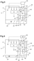
- Said fluid system comprises a reservoir containing a lubricating fluid, the reservoir being for example inside a casing of the mechanical system, said fluid system comprising a spray circuit provided with at least one sprinkler, said fluid system comprising a main fluid circuit extending from the reservoir to the spray circuit, said fluid system comprising a backup fluid circuit extending from the reservoir and joining said spray circuit, for example downstream of the main fluid circuit in the direction of circulation of the lubricating fluid, said backup fluid circuit comprising an backup non-return valve provided with a blocker movable from a closed position preventing circulation of said lubricating fluid to a open position allowing passage of said lubricating fluid from the tank to the spray circuit, said emergency fluid circuit being sized so that the emergency non-return valve is in the closed state in a nominal operating mode.
- the expression "in the presence of a said detection of a malfunction and a detection that the blocker is stable in the open position” means that the first alert is issued as long as, on the one hand, a malfunction rendering the main fluid circuit inoperative is detected and, on the other hand, the blocker remains in its open position. The fluid system is then in a degraded operating mode during which the emergency fluid circuit operates normally.
- the open position can be any position other than the closed position, or a specific position.
- the spray circuit may, for example, comprise a distribution section equipped with at least one sprinkler, for example located in the mechanical system to be lubricated, or even a filter, for example, accompanied by a bypass line.
- the spray circuit may, for example, comprise a first section hydraulically connecting the distribution section to the emergency non-return valve.
- the spray circuit may optionally comprise a second section hydraulically connecting, for example upstream of the first section, the distribution section to the main fluid circuit and possibly to a main non-return valve of the main fluid circuit.
- a lubricating fluid may be called “lubricating and/or cooling fluid” and may comprise a liquid and in particular oil.
- the method of the invention comprises a step of detecting a malfunction rendering the main fluid circuit inoperative.
- a malfunction rendering the main fluid circuit inoperative.
- the fluid system is in fact inoperative or in a degraded operating mode during which an alert is generated.
- the nature of the alert depends on the behavior of the blocker of the emergency non-return valve.
- a first alert is issued.
- This first alert means that the emergency fluid circuit is operational since the non-return valve of emergency is open.
- the mechanical system is therefore lubricated via the emergency fluid circuit. The flight can possibly continue under these conditions.
- a second alert is generated.
- This second alert means that the main fluid circuit and the emergency fluid circuit are inoperative because the emergency check valve is closed.
- the mechanical system is therefore no longer lubricated.
- the aircraft may need to be landed immediately, possibly on a liquid surface if flying over a sea.
- the process can thus identify the current operation of the fluid system. This process can identify the presence of a malfunction, or even identify that the main fluid circuit is no longer supplying lubrication fluid to the spray circuit and identify whether the backup fluid circuit has taken over, even weakly.
- the main fluid circuit can be sized so that the pressure of the lubricating fluid in the spray circuit is higher than the pressure reached when the emergency fluid circuit is active, namely when the emergency non-return valve is in the open state.
- the emergency non-return valve is sized to be closed under the effect of the pressure of the lubricating fluid injected into the spray circuit by the main fluid circuit during the nominal operating mode.
- the monitoring parameter has a first value substantially equivalent to the pressure of the lubricating fluid at the outlet of the main fluid circuit.
- comparing a measured pressure in the sprinkler circuit to a predetermined pressure threshold can help determine whether the main fluid circuit is deficient.
- the predetermined pressure threshold may be less than or equal to the first value, and greater than or equal to the second value.
- said main fluid circuit may comprise a main non-return valve configured to be either in a closed state or in an open state allowing passage of said lubricating fluid from the reservoir to the spray circuit.
- the main check valve In the nominal operating mode, the main check valve must be open. If the main check valve is in its closed state or tends to open and close successively, then the main fluid circuit is no longer operative.
- the condition of the main check valve can be assessed in a conventional manner, for example using one of the methods described above.
- the monitoring phase is undertaken only when the mechanical system is in operation to avoid the emission of an alert when the mechanical system is started.
- the step of detecting that the mechanical system is in operation may comprise a measurement of a speed of movement of a moving member of the mechanical system, the monitoring phase being initiated when this moving member moves, relative to a casing for example, with a speed greater than a speed threshold.
- the monitoring phase is undertaken after a predetermined period following start-up or according to another criterion and for example on the order of another system.
- the monitoring phase is undertaken from the start.
- the first alert may carry a flight authorization in normal flight conditions
- the second alert may carry a flight authorization to land the aircraft immediately, namely within a limited time
- said third alert may carry a flight authorization by applying predetermined instructions to fly in reduced load conditions and/or may carry a landing order on a practicable landing area.
- the blocker can be considered to be stable in the open position when the blocker is in the open position for at least a predetermined duration called "predetermined opening duration" for convenience.
- the blocker can be considered to be stable in the closed position when the blocker is in the closed position for at least a predetermined duration called the “predetermined closing duration” for convenience.
- the predetermined opening time and the predetermined closing time may be equal, for example of the order of one minute, or different.
- the predetermined opening time and the predetermined closing time may be determined by testing or simulation, for example.
- the alerter considers that the blocker is flapping when, at a given moment, the blocker is not in the open position at least for the predetermined opening time and the blocker is not in the closed position at least for the predetermined closing time.
- the method can comprise during the transient phase at least one of the following measurements: measurement of a duration between a passage of the blocker from the open position to the closed position, measurement of a duration between a passage of the blocker from the closed position to the open position, measurement of a duration between a passage of the blocker from the open position to the closed position then to the open position, measurement of an amplitude of movement of the blocker.
- the method may include displaying on a display the previous measurement(s) taken to assist a pilot in understanding the current situation.
- the invention relates to a fluidic system applying this method.
- Such a fluid system comprises a reservoir containing a lubricating fluid, for example inside a casing of the mechanical system, said fluid system comprising a spray circuit provided with at least one sprinkler, said fluid system comprising a main fluid circuit extending from the reservoir to the spray circuit, said fluid system comprising a backup fluid circuit extending from the reservoir and joining said spray circuit for example downstream of the main fluid circuit, said backup fluid circuit comprising an backup non-return valve provided with a blocker movable from a closed position preventing circulation of said lubricating fluid to an open position allowing passage of said lubricating fluid from the reservoir to the spray circuit.
- said fluidic system is configured to apply the method of the invention, said fluidic system comprising at least one malfunction sensor for performing said detection of a malfunction, said fluidic system having a backup state sensor configured to measure a position of the blocker, the fluidic system having an alerter in communication with the backup state sensor and the malfunction sensor, the alerter being configured to perform said generation of the first alert and said generation of the second alert and said generation of the third alert.
- said at least one malfunction sensor may comprise a pressure sensor emitting a pressure signal varying as a function of a pressure prevailing in said spray circuit, said pressure signal being transmitted to the alarm.
Landscapes
- Engineering & Computer Science (AREA)
- General Engineering & Computer Science (AREA)
- Mechanical Engineering (AREA)
- Physics & Mathematics (AREA)
- General Physics & Mathematics (AREA)
- Aviation & Aerospace Engineering (AREA)
- Chemical & Material Sciences (AREA)
- Combustion & Propulsion (AREA)
- Oil, Petroleum & Natural Gas (AREA)
- Fluid-Pressure Circuits (AREA)
- Measuring Volume Flow (AREA)
- Indicating Or Recording The Presence, Absence, Or Direction Of Movement (AREA)
Claims (13)
- Verfahren zum Überwachen eines Fluidsystems (20) zum Schmieren eines mechanischen Systems (5), wobei das Fluidsystem (20) einen Behälter (25) umfasst, der ein Schmierfluid (26) enthält, wobei das Fluidsystem (20) einen Sprühkreis (30) mit mindestens einem Sprühkopf (33) umfasst, wobei das Fluidsystem (20) einen Hauptfluidkreis (40) umfasst, der sich vom Vorratsbehälter (25) bis zum Sprühkreis (30) erstreckt, wobei das Fluidsystem (20) einen Notfluidkreis (60) umfasst, der sich vom Behälter (25) erstreckt und den Sprühkreis (30) erreicht, wobei der Notfluidkreis (60) ein Notrückschlagventil (70) mit einer Sperre (71) aufweist, die aus einer geschlossenen Position (POSF), in der sie einen Durchfluss des Schmierfluids (26) verhindert, in eine offene Position (POSO) bewegbar ist, in der sie einen Durchfluss des Schmierfluids (26) vom Behälter (25) zum Sprühkreislauf (30) ermöglicht, wobei der Notfluidkreis (60) so dimensioniert ist, dass sich das Notrückschlagventil (70) in einem Nennbetriebsmodus im geschlossenen Zustand befindet, wobei das Verfahren eine Überwachungsphase (STPB) umfasst, die die folgenden Schritte umfasst:- Erfassen einer Störung (STPB11) durch Überwachen mindestens eines Überwachungsparameters, wobei die Störung den Hauptfluidkreis (40) außer Betrieb setzt,- Messen (STPB12) einer Position der Sperre (71) innerhalb des Notrückschlagventils (70),- Erzeugen (STPB21) einer ersten Warnung bei Vorliegen einer besagten Erfassung einer Störung und einer Erfassung, dass die Sperre (71) in der offenen Position stabil ist, wobei die Sperre (71) dann in der offenen Position stabil ist, wenn sich die Sperre (71) mindestens während einer vorgegebenen Öffnungsdauer in der offenen Position befindet,- Erzeugen (STPB22) einer zweiten Warnung, die sich von der ersten Warnung unterscheidet, bei Vorliegen einer besagten Erfassung einer Störung und einer Erfassung, dass die Sperre (71) in der geschlossenen Position stabil ist, wobei die Sperre (71) dann in der geschlossenen Position stabil ist, wenn sich die Sperre (71) mindestens während einer vorgegebenen Schließdauer in der geschlossenen Position befindet,dadurch gekennzeichnet, dass die Überwachungsphase (STPB) den folgenden Schritt umfasst:- Erzeugen (STPB23) einer dritten, von der ersten Warnung und der zweiten Warnung verschiedenen Warnung bei Vorliegen einer besagten Erfassung einer Störung und einer Erfassung, dass sich die Sperre (71) in einer Übergangsphase befindet, in der die Sperre (71) wackelt.
- Verfahren nach Anspruch 1,
dadurch gekennzeichnet, dass der mindestens eine Überwachungsparameter ein in dem Sprühkreis (30) herrschender Druck ist, wobei die Erfassung einer Störung durch Überwachen mindestens eines Überwachungsparameters einen Schritt umfasst, bei dem mit einem Drucksensor (81) erfasst wird, dass der Druck unter einem vorgegebenen Druckschwellenwert liegt. - Verfahren nach Anspruch 1,dadurch gekennzeichnet, dass der Hauptfluidkreis (40) ein Hauptrückschlagventil (50) umfasst, das konfiguriert ist, um entweder einen geschlossenen Zustand oder einen offenen Zustand einzunehmen, der einen Durchfluss des Schmierfluids (26) vom Vorratsbehälter (25) zum Sprühkreis (30) ermöglicht,wobei der mindestens eine Überwachungsparameter den offenen oder geschlossenen Zustand des Hauptrückschlagventils (50) angibt,wobei die Erfassung einer Störung durch Überwachen mindestens eines Überwachungsparameters einen Schritt umfasst, bei dem erkannt wird, dass sich das Hauptrückschlagventil (50) in einem anderen Zustand als dem offenen Zustand befindet.
- Verfahren nach einem der Ansprüche 1 bis 3,
dadurch gekennzeichnet, dass das Verfahren einen Schritt des Erfassens (STPA) umfasst, dass das mechanische System (5) in Betrieb ist, wobei die Überwachungsphase (STPB) durchgeführt wird, wenn das mechanische System (5) in Betrieb ist. - Verfahren nach einem der Ansprüche 1 bis 4,
dadurch gekennzeichnet, dass das mechanische System (5) in einem Luftfahrzeug (2) angeordnet ist, wobei die erste Warnung eine Flugfreigabe für eine erste Dauer enthält und die zweite Warnung eine Flugfreigabe für eine zweite Dauer enthält, die kürzer ist als die erste Dauer, und die dritte Warnung eine Flugfreigabe für mindestens die erste Dauer enthält. - Verfahren nach einem der Ansprüche 1 bis 5,
dadurch gekennzeichnet, dass das Verfahren während der Übergangsphase mindestens eine der folgenden Messungen umfasst: Messen einer Zeitdauer zwischen einem Übergang der Sperre von der offenen Position in die geschlossene Position, Messen einer Zeitdauer zwischen einem Übergang der Sperre von der geschlossenen Position in die offene Position, Messen einer Zeitdauer zwischen einem Übergang der Sperre von der offenen Position in die geschlossene Position und anschließend in die offene Position, Messen einer Bewegungsamplitude der Sperre. - Fluidsystem (20) mit einem Behälter (25), der ein Schmierfluid (26) enthält, wobei das Fluidsystem (20) einen Sprühkreis (30) mit mindestens einem Sprühkopf (33) umfasst, wobei das Fluidsystem (20) einen Hauptfluidkreis (40) umfasst, der sich vom Behälter bis zum Sprühkreis (30) erstreckt, wobei das Fluidsystem (20) einen Notfluidkreis (60) umfasst, der sich vom Behälter (25) aus erstreckt und den Sprühkreis (30) erreicht, wobei der Notfluidkreis (60) ein Notrückschlagventil (70) mit einer Sperre (71) aufweist, die aus einer geschlossenen Position, in der sie einen Durchfluss des Schmierfluids (26) verhindert, in eine offene Position bewegbar ist, in der sie einen Durchfluss des Schmierfluids (26) aus dem Behälter (25) zum Sprühkreislauf (30) ermöglicht, wobei das Fluidsystem (20) mindestens einen Störungssensor (80) umfasst, um die Erfassung einer Störung nach Anspruch 1 durchzuführen, wobei das Fluidsystem (20) einen Positionssensor (85) aufweist, der konfiguriert ist, um eine Position der Sperre (71) zu messen, und das Fluidsystem (20) eine Warnvorrichtung (90) aufweist, die mit dem Notfallzustandssensor (85) und dem Funktionsstörungssensor (80) kommuniziert,
dadurch gekennzeichnet, dass das Fluidsystem (20) konfiguriert ist, um das Verfahren nach einem der Ansprüche 1 bis 6 durchzuführen, und die Warnvorrichtung (90) konfiguriert ist, um die Erzeugung der ersten Warnung und die Erzeugung der zweiten Warnung und die Erzeugung der dritten Warnung durchzuführen. - Fluidsystem (20) nach Anspruch 7,
dadurch gekennzeichnet, dass der Störungssensor (80) einen Drucksensor (81) umfasst, der ein Drucksignal ausgibt, das in Abhängigkeit von einem in dem Sprühkreis (30) herrschenden Druck variiert, wobei das Drucksignal an die Warnvorrichtung (90) übertragen wird. - Fluidsystem (20) nach einem der Ansprüche 7 bis 8,
dadurch gekennzeichnet, dass der Hauptfluidkreis (40) ein Hauptrückschlagventil (50) aufweist, das konfiguriert ist, um entweder in einem geschlossenen Zustand oder in einem offenen Zustand zu sein, der einen Durchfluss des Schmierfluids (26) vom Behälter (25) zum Sprühkreis (30) ermöglicht, wobei der Störungssensor (80) einen Hauptzustandssensor (82) umfasst, der konfiguriert ist, um zu erfassen, ob sich das Hauptrückschlagventil (50) in dem offenen Zustand oder dem geschlossenen Zustand befindet. - Fluidsystem (20) nach einem der Ansprüche 7 bis 9,
dadurch gekennzeichnet, dass das Fluidsystem (20) einen Funktionssensor (95) aufweist, um zu erfassen, ob das mechanische System (5) in Betrieb ist. - Baugruppe (4) mit einem mechanischen System (5), das mindestens ein zu schmierendes Element (6) und ein Fluidsystem (20) zum Schmieren des mindestens einen zu schmierenden Elements (6) umfasst,
dadurch gekennzeichnet, dass das Fluidsystem (20) gemäß einem der Ansprüche 7 bis 10 ausgebildet ist. - Baugruppe nach Anspruch 11,
dadurch gekennzeichnet, dass das Notrückschlagventil (70) in den Sprühkreis (30) mündet. - Verkehrsmittel (1) mit einer Baugruppe (4), dadurch gekennzeichnet, dass die Baugruppe (4) nach einem der Ansprüche 11 bis 12 ausgebildet ist.
Applications Claiming Priority (1)
| Application Number | Priority Date | Filing Date | Title |
|---|---|---|---|
| FR2208736A FR3139196B1 (fr) | 2022-08-31 | 2022-08-31 | Procede de surveillance d’un systeme fluidique lubrifiant un systeme mecanique |
Publications (2)
| Publication Number | Publication Date |
|---|---|
| EP4331980A1 EP4331980A1 (de) | 2024-03-06 |
| EP4331980B1 true EP4331980B1 (de) | 2025-07-02 |
Family
ID=86469346
Family Applications (1)
| Application Number | Title | Priority Date | Filing Date |
|---|---|---|---|
| EP23175907.7A Active EP4331980B1 (de) | 2022-08-31 | 2023-05-29 | Verfahren zur überwachung eines schmierenden fluidsystems eines mechanischen systems |
Country Status (2)
| Country | Link |
|---|---|
| EP (1) | EP4331980B1 (de) |
| FR (1) | FR3139196B1 (de) |
Family Cites Families (6)
| Publication number | Priority date | Publication date | Assignee | Title |
|---|---|---|---|---|
| FR2658577A1 (fr) | 1990-02-20 | 1991-08-23 | Aerospatiale | Dispositif de lubrification de secours pour reducteur notamment pour boite de transmission principale de giravion. |
| FR2685758B1 (fr) | 1991-12-26 | 1995-03-31 | Aerospatiale | Systeme de lubrification et de refroidissement de secours d'un multiplicateur/reducteur mecanique du type "boite de transmission" d'helicoptere en cas de defaillance du circuit de lubrification. |
| FR2826094B1 (fr) | 2001-06-15 | 2003-11-28 | Eurocopter France | Systeme de lubrification et de refroidissement d'un ensemble mecanique |
| US10145276B2 (en) * | 2015-06-23 | 2018-12-04 | United Technologies Corporation | Lubricant valve monitoring method and assembly |
| FR3045764B1 (fr) | 2015-12-17 | 2017-12-22 | Airbus Helicopters | Dispositif de lubrification de secours a architecture simplifiee pour une boite de transmission principale de puissance d'un aeronef |
| FR3112835B1 (fr) | 2020-07-21 | 2022-06-24 | Airbus Helicopters | Procédé de surveillance d’un système fluidique lubrifiant un système mécanique |
-
2022
- 2022-08-31 FR FR2208736A patent/FR3139196B1/fr active Active
-
2023
- 2023-05-29 EP EP23175907.7A patent/EP4331980B1/de active Active
Also Published As
| Publication number | Publication date |
|---|---|
| FR3139196B1 (fr) | 2024-07-26 |
| EP4331980A1 (de) | 2024-03-06 |
| FR3139196A1 (fr) | 2024-03-01 |
Similar Documents
| Publication | Publication Date | Title |
|---|---|---|
| EP3943783B1 (de) | Verfahren zur überwachung eines flüssigkeitssystems zur schmierung eines mechanischen systems | |
| EP3015743B1 (de) | Schmierverfahren und -vorrichtung mit verbesserter zuverlässigkeit mit dreifachkreislauf eines hauptleistungsübertragungsgetriebes eines luftfahrzeugs | |
| EP3181951B1 (de) | Not-schmiervorrichtung mit vereinfachtem aufbau für ein hauptleistungsübertragungsgetriebe eines luftfahrzeugs | |
| EP3021030B1 (de) | Schmierverfahren und -vorrichtung mit verbesserter zuverlässigkeit mit doppelkreislauf eines hauptleistungsübertragungsgetriebes eines luftfahrzeugs | |
| EP3084187B1 (de) | Flüssigkeitsabflussvorrichtung für ein flugzeugtriebwerk | |
| EP3104044B1 (de) | Leistungsübertragungsgetriebe und luftfahrzeug | |
| JP5546470B2 (ja) | 軸受の保守装置 | |
| EP4284685B1 (de) | Verfahren zur funktionsüberprüfung eines fahrzeugoberflächenreinigungsgerätes | |
| FR3068757A1 (fr) | Dispositif d'etancheite pour arbre de propulsion d'une unite de propulsion de vehicule marin | |
| CN112334683B (zh) | 飞行器涡轮发动机的组件及其控制方法,飞行器涡轮发动机 | |
| FR3045197A1 (fr) | Procede et systeme ameliores d'aide au pilotage d'un aeronef en phase d'atterrissage | |
| EP4257866A1 (de) | Mechanisches system mit einem gehäuse, das über schmier- oder kühlelemente eines tanks eines schmierenden fluidsystems untergebracht ist | |
| EP4331980A1 (de) | Verfahren zur überwachung eines schmierenden fluidsystems eines mechanischen systems | |
| EP3978784A1 (de) | Schmiersystem mit einem ersatzbehälter | |
| FR2500578A1 (fr) | Buse a double fonction pour lubrification de secours par brouillard d'huile | |
| FR2680393A1 (fr) | Procede et dispositif de commande d'une installation de pompage. | |
| EP4409115B1 (de) | Hilfsöltank für ein flugzeugturbinentriebwerk | |
| EP4232325A1 (de) | Reinigungssystem für ein kraftfahrzeug | |
| FR2911283A1 (fr) | Perfectionnement aux dispositifs mobiles pour la lutte contre l'incendie du type vehicules incendie ou motopompe incendie | |
| EP0291370B1 (de) | Überwachungsvorrichtung des Druckes einer Ölpumpe angetrieben durch die Übertragung eines Kraftfahrzeuges | |
| EP1681470A1 (de) | Feuerlöschkreiselpumpe mit Vorrichtung zur Kavitationsdetektion | |
| FR3083283A1 (fr) | Systeme de lubrification pour une boite de transmission principale de puissance d 'un aeronef avec une dispositif ameliore de captation et de detection des particules metalliques | |
| FR3073916A1 (fr) | Circuit fluidique pour lubrifier et/ou refroidir un ensemble mecanique | |
| FR3159215A1 (fr) | Système mécanique muni d’éléments mécaniques mobiles, d’un bouchon magnétique ainsi que d’un système de lubrification muni de filtres mécanique et magnétique. | |
| FR3074558A1 (fr) | Systeme fluidique pour lubrifier et/ou refroidir un ensemble mecanique |
Legal Events
| Date | Code | Title | Description |
|---|---|---|---|
| PUAI | Public reference made under article 153(3) epc to a published international application that has entered the european phase |
Free format text: ORIGINAL CODE: 0009012 |
|
| STAA | Information on the status of an ep patent application or granted ep patent |
Free format text: STATUS: THE APPLICATION HAS BEEN PUBLISHED |
|
| AK | Designated contracting states |
Kind code of ref document: A1 Designated state(s): AL AT BE BG CH CY CZ DE DK EE ES FI FR GB GR HR HU IE IS IT LI LT LU LV MC ME MK MT NL NO PL PT RO RS SE SI SK SM TR |
|
| STAA | Information on the status of an ep patent application or granted ep patent |
Free format text: STATUS: REQUEST FOR EXAMINATION WAS MADE |
|
| 17P | Request for examination filed |
Effective date: 20240312 |
|
| P01 | Opt-out of the competence of the unified patent court (upc) registered |
Effective date: 20240312 |
|
| RBV | Designated contracting states (corrected) |
Designated state(s): AL AT BE BG CH CY CZ DE DK EE ES FI FR GB GR HR HU IE IS IT LI LT LU LV MC ME MK MT NL NO PL PT RO RS SE SI SK SM TR |
|
| GRAP | Despatch of communication of intention to grant a patent |
Free format text: ORIGINAL CODE: EPIDOSNIGR1 |
|
| STAA | Information on the status of an ep patent application or granted ep patent |
Free format text: STATUS: GRANT OF PATENT IS INTENDED |
|
| RIC1 | Information provided on ipc code assigned before grant |
Ipc: B64D 33/00 20060101ALI20250307BHEP Ipc: G01M 13/02 20190101ALI20250307BHEP Ipc: F16N 29/04 20060101ALI20250307BHEP Ipc: F16N 7/32 20060101ALI20250307BHEP Ipc: F16H 57/04 20100101ALI20250307BHEP Ipc: B64C 27/12 20060101AFI20250307BHEP |
|
| INTG | Intention to grant announced |
Effective date: 20250327 |
|
| RAP3 | Party data changed (applicant data changed or rights of an application transferred) |
Owner name: AIRBUS HELICOPTERS |
|
| RIN1 | Information on inventor provided before grant (corrected) |
Inventor name: BASSO, BENOIT Inventor name: CHARRIER, MATHIEU Inventor name: ESCOFFIER, ADRIEN |
|
| GRAS | Grant fee paid |
Free format text: ORIGINAL CODE: EPIDOSNIGR3 |
|
| GRAA | (expected) grant |
Free format text: ORIGINAL CODE: 0009210 |
|
| STAA | Information on the status of an ep patent application or granted ep patent |
Free format text: STATUS: THE PATENT HAS BEEN GRANTED |
|
| AK | Designated contracting states |
Kind code of ref document: B1 Designated state(s): AL AT BE BG CH CY CZ DE DK EE ES FI FR GB GR HR HU IE IS IT LI LT LU LV MC ME MK MT NL NO PL PT RO RS SE SI SK SM TR |
|
| REG | Reference to a national code |
Ref country code: GB Ref legal event code: FG4D Free format text: NOT ENGLISH |
|
| REG | Reference to a national code |
Ref country code: CH Ref legal event code: EP |
|
| REG | Reference to a national code |
Ref country code: DE Ref legal event code: R096 Ref document number: 602023004449 Country of ref document: DE |
|
| REG | Reference to a national code |
Ref country code: IE Ref legal event code: FG4D Free format text: LANGUAGE OF EP DOCUMENT: FRENCH |
|
| REG | Reference to a national code |
Ref country code: NL Ref legal event code: MP Effective date: 20250702 |
|
| PG25 | Lapsed in a contracting state [announced via postgrant information from national office to epo] |
Ref country code: PT Free format text: LAPSE BECAUSE OF FAILURE TO SUBMIT A TRANSLATION OF THE DESCRIPTION OR TO PAY THE FEE WITHIN THE PRESCRIBED TIME-LIMIT Effective date: 20251103 |
|
| PG25 | Lapsed in a contracting state [announced via postgrant information from national office to epo] |
Ref country code: NL Free format text: LAPSE BECAUSE OF FAILURE TO SUBMIT A TRANSLATION OF THE DESCRIPTION OR TO PAY THE FEE WITHIN THE PRESCRIBED TIME-LIMIT Effective date: 20250702 |
|
| REG | Reference to a national code |
Ref country code: AT Ref legal event code: MK05 Ref document number: 1808981 Country of ref document: AT Kind code of ref document: T Effective date: 20250702 |
|
| PG25 | Lapsed in a contracting state [announced via postgrant information from national office to epo] |
Ref country code: IS Free format text: LAPSE BECAUSE OF FAILURE TO SUBMIT A TRANSLATION OF THE DESCRIPTION OR TO PAY THE FEE WITHIN THE PRESCRIBED TIME-LIMIT Effective date: 20251102 |
|
| PG25 | Lapsed in a contracting state [announced via postgrant information from national office to epo] |
Ref country code: NO Free format text: LAPSE BECAUSE OF FAILURE TO SUBMIT A TRANSLATION OF THE DESCRIPTION OR TO PAY THE FEE WITHIN THE PRESCRIBED TIME-LIMIT Effective date: 20251002 |
|
| REG | Reference to a national code |
Ref country code: LT Ref legal event code: MG9D |
|
| PG25 | Lapsed in a contracting state [announced via postgrant information from national office to epo] |
Ref country code: AT Free format text: LAPSE BECAUSE OF FAILURE TO SUBMIT A TRANSLATION OF THE DESCRIPTION OR TO PAY THE FEE WITHIN THE PRESCRIBED TIME-LIMIT Effective date: 20250702 |
|
| PG25 | Lapsed in a contracting state [announced via postgrant information from national office to epo] |
Ref country code: FI Free format text: LAPSE BECAUSE OF FAILURE TO SUBMIT A TRANSLATION OF THE DESCRIPTION OR TO PAY THE FEE WITHIN THE PRESCRIBED TIME-LIMIT Effective date: 20250702 |
|
| PG25 | Lapsed in a contracting state [announced via postgrant information from national office to epo] |
Ref country code: HR Free format text: LAPSE BECAUSE OF FAILURE TO SUBMIT A TRANSLATION OF THE DESCRIPTION OR TO PAY THE FEE WITHIN THE PRESCRIBED TIME-LIMIT Effective date: 20250702 |
|
| PG25 | Lapsed in a contracting state [announced via postgrant information from national office to epo] |
Ref country code: GR Free format text: LAPSE BECAUSE OF FAILURE TO SUBMIT A TRANSLATION OF THE DESCRIPTION OR TO PAY THE FEE WITHIN THE PRESCRIBED TIME-LIMIT Effective date: 20251003 |
|
| PG25 | Lapsed in a contracting state [announced via postgrant information from national office to epo] |
Ref country code: SE Free format text: LAPSE BECAUSE OF FAILURE TO SUBMIT A TRANSLATION OF THE DESCRIPTION OR TO PAY THE FEE WITHIN THE PRESCRIBED TIME-LIMIT Effective date: 20250702 Ref country code: CZ Free format text: LAPSE BECAUSE OF FAILURE TO SUBMIT A TRANSLATION OF THE DESCRIPTION OR TO PAY THE FEE WITHIN THE PRESCRIBED TIME-LIMIT Effective date: 20250702 |
|
| PG25 | Lapsed in a contracting state [announced via postgrant information from national office to epo] |
Ref country code: LV Free format text: LAPSE BECAUSE OF FAILURE TO SUBMIT A TRANSLATION OF THE DESCRIPTION OR TO PAY THE FEE WITHIN THE PRESCRIBED TIME-LIMIT Effective date: 20250702 |
|
| PG25 | Lapsed in a contracting state [announced via postgrant information from national office to epo] |
Ref country code: PL Free format text: LAPSE BECAUSE OF FAILURE TO SUBMIT A TRANSLATION OF THE DESCRIPTION OR TO PAY THE FEE WITHIN THE PRESCRIBED TIME-LIMIT Effective date: 20250702 Ref country code: BG Free format text: LAPSE BECAUSE OF FAILURE TO SUBMIT A TRANSLATION OF THE DESCRIPTION OR TO PAY THE FEE WITHIN THE PRESCRIBED TIME-LIMIT Effective date: 20250702 |
|
| PG25 | Lapsed in a contracting state [announced via postgrant information from national office to epo] |
Ref country code: RS Free format text: LAPSE BECAUSE OF FAILURE TO SUBMIT A TRANSLATION OF THE DESCRIPTION OR TO PAY THE FEE WITHIN THE PRESCRIBED TIME-LIMIT Effective date: 20251002 |
|
| PG25 | Lapsed in a contracting state [announced via postgrant information from national office to epo] |
Ref country code: ES Free format text: LAPSE BECAUSE OF FAILURE TO SUBMIT A TRANSLATION OF THE DESCRIPTION OR TO PAY THE FEE WITHIN THE PRESCRIBED TIME-LIMIT Effective date: 20250702 |
|
| PG25 | Lapsed in a contracting state [announced via postgrant information from national office to epo] |
Ref country code: SM Free format text: LAPSE BECAUSE OF FAILURE TO SUBMIT A TRANSLATION OF THE DESCRIPTION OR TO PAY THE FEE WITHIN THE PRESCRIBED TIME-LIMIT Effective date: 20250702 |
|
| PG25 | Lapsed in a contracting state [announced via postgrant information from national office to epo] |
Ref country code: DK Free format text: LAPSE BECAUSE OF FAILURE TO SUBMIT A TRANSLATION OF THE DESCRIPTION OR TO PAY THE FEE WITHIN THE PRESCRIBED TIME-LIMIT Effective date: 20250702 |
|
| PG25 | Lapsed in a contracting state [announced via postgrant information from national office to epo] |
Ref country code: SK Free format text: LAPSE BECAUSE OF FAILURE TO SUBMIT A TRANSLATION OF THE DESCRIPTION OR TO PAY THE FEE WITHIN THE PRESCRIBED TIME-LIMIT Effective date: 20250702 Ref country code: EE Free format text: LAPSE BECAUSE OF FAILURE TO SUBMIT A TRANSLATION OF THE DESCRIPTION OR TO PAY THE FEE WITHIN THE PRESCRIBED TIME-LIMIT Effective date: 20250702 |
|
| PLBE | No opposition filed within time limit |
Free format text: ORIGINAL CODE: 0009261 |
|
| STAA | Information on the status of an ep patent application or granted ep patent |
Free format text: STATUS: NO OPPOSITION FILED WITHIN TIME LIMIT |