EP3941660B1 - Stützwerkzeug für poröse vorformen und ofen mit einem solchen werkzeug - Google Patents
Stützwerkzeug für poröse vorformen und ofen mit einem solchen werkzeug Download PDFInfo
- Publication number
- EP3941660B1 EP3941660B1 EP20725888.0A EP20725888A EP3941660B1 EP 3941660 B1 EP3941660 B1 EP 3941660B1 EP 20725888 A EP20725888 A EP 20725888A EP 3941660 B1 EP3941660 B1 EP 3941660B1
- Authority
- EP
- European Patent Office
- Prior art keywords
- support
- porous
- tooling
- preforms
- molten metal
- Prior art date
- Legal status (The legal status is an assumption and is not a legal conclusion. Google has not performed a legal analysis and makes no representation as to the accuracy of the status listed.)
- Active
Links
Images




Classifications
-
- B—PERFORMING OPERATIONS; TRANSPORTING
- B22—CASTING; POWDER METALLURGY
- B22D—CASTING OF METALS; CASTING OF OTHER SUBSTANCES BY THE SAME PROCESSES OR DEVICES
- B22D19/00—Casting in, on, or around objects which form part of the product
- B22D19/14—Casting in, on, or around objects which form part of the product the objects being filamentary or particulate in form
-
- F—MECHANICAL ENGINEERING; LIGHTING; HEATING; WEAPONS; BLASTING
- F27—FURNACES; KILNS; OVENS; RETORTS
- F27D—DETAILS OR ACCESSORIES OF FURNACES, KILNS, OVENS OR RETORTS, IN SO FAR AS THEY ARE OF KINDS OCCURRING IN MORE THAN ONE KIND OF FURNACE
- F27D5/00—Supports, screens or the like for the charge within the furnace
- F27D5/0056—Hangers
-
- C—CHEMISTRY; METALLURGY
- C04—CEMENTS; CONCRETE; ARTIFICIAL STONE; CERAMICS; REFRACTORIES
- C04B—LIME, MAGNESIA; SLAG; CEMENTS; COMPOSITIONS THEREOF, e.g. MORTARS, CONCRETE OR LIKE BUILDING MATERIALS; ARTIFICIAL STONE; CERAMICS; REFRACTORIES; TREATMENT OF NATURAL STONE
- C04B41/00—After-treatment of mortars, concrete, artificial stone or ceramics; Treatment of natural stone
- C04B41/45—Coating or impregnating, e.g. injection in masonry, partial coating of green or fired ceramics, organic coating compositions for adhering together two concrete elements
- C04B41/50—Coating or impregnating, e.g. injection in masonry, partial coating of green or fired ceramics, organic coating compositions for adhering together two concrete elements with inorganic materials
- C04B41/5093—Coating or impregnating, e.g. injection in masonry, partial coating of green or fired ceramics, organic coating compositions for adhering together two concrete elements with inorganic materials with elements other than metals or carbon
- C04B41/5096—Silicon
-
- C—CHEMISTRY; METALLURGY
- C04—CEMENTS; CONCRETE; ARTIFICIAL STONE; CERAMICS; REFRACTORIES
- C04B—LIME, MAGNESIA; SLAG; CEMENTS; COMPOSITIONS THEREOF, e.g. MORTARS, CONCRETE OR LIKE BUILDING MATERIALS; ARTIFICIAL STONE; CERAMICS; REFRACTORIES; TREATMENT OF NATURAL STONE
- C04B41/00—After-treatment of mortars, concrete, artificial stone or ceramics; Treatment of natural stone
- C04B41/45—Coating or impregnating, e.g. injection in masonry, partial coating of green or fired ceramics, organic coating compositions for adhering together two concrete elements
- C04B41/50—Coating or impregnating, e.g. injection in masonry, partial coating of green or fired ceramics, organic coating compositions for adhering together two concrete elements with inorganic materials
- C04B41/51—Metallising, e.g. infiltration of sintered ceramic preforms with molten metal
-
- C—CHEMISTRY; METALLURGY
- C04—CEMENTS; CONCRETE; ARTIFICIAL STONE; CERAMICS; REFRACTORIES
- C04B—LIME, MAGNESIA; SLAG; CEMENTS; COMPOSITIONS THEREOF, e.g. MORTARS, CONCRETE OR LIKE BUILDING MATERIALS; ARTIFICIAL STONE; CERAMICS; REFRACTORIES; TREATMENT OF NATURAL STONE
- C04B41/00—After-treatment of mortars, concrete, artificial stone or ceramics; Treatment of natural stone
- C04B41/80—After-treatment of mortars, concrete, artificial stone or ceramics; Treatment of natural stone of only ceramics
- C04B41/81—Coating or impregnation
- C04B41/85—Coating or impregnation with inorganic materials
- C04B41/88—Metals
-
- C—CHEMISTRY; METALLURGY
- C22—METALLURGY; FERROUS OR NON-FERROUS ALLOYS; TREATMENT OF ALLOYS OR NON-FERROUS METALS
- C22C—ALLOYS
- C22C1/00—Making non-ferrous alloys
- C22C1/10—Alloys containing non-metals
- C22C1/1036—Alloys containing non-metals starting from a melt
-
- C—CHEMISTRY; METALLURGY
- C22—METALLURGY; FERROUS OR NON-FERROUS ALLOYS; TREATMENT OF ALLOYS OR NON-FERROUS METALS
- C22C—ALLOYS
- C22C47/00—Making alloys containing metallic or non-metallic fibres or filaments
- C22C47/08—Making alloys containing metallic or non-metallic fibres or filaments by contacting the fibres or filaments with molten metal, e.g. by infiltrating the fibres or filaments placed in a mould
-
- C—CHEMISTRY; METALLURGY
- C23—COATING METALLIC MATERIAL; COATING MATERIAL WITH METALLIC MATERIAL; CHEMICAL SURFACE TREATMENT; DIFFUSION TREATMENT OF METALLIC MATERIAL; COATING BY VACUUM EVAPORATION, BY SPUTTERING, BY ION IMPLANTATION OR BY CHEMICAL VAPOUR DEPOSITION, IN GENERAL; INHIBITING CORROSION OF METALLIC MATERIAL OR INCRUSTATION IN GENERAL
- C23C—COATING METALLIC MATERIAL; COATING MATERIAL WITH METALLIC MATERIAL; SURFACE TREATMENT OF METALLIC MATERIAL BY DIFFUSION INTO THE SURFACE, BY CHEMICAL CONVERSION OR SUBSTITUTION; COATING BY VACUUM EVAPORATION, BY SPUTTERING, BY ION IMPLANTATION OR BY CHEMICAL VAPOUR DEPOSITION, IN GENERAL
- C23C2/00—Hot-dipping or immersion processes for applying the coating material in the molten state without affecting the shape; Apparatus therefor
- C23C2/003—Apparatus
- C23C2/0032—Apparatus specially adapted for batch coating of substrate
- C23C2/00322—Details of mechanisms for immersing or removing substrate from molten liquid bath, e.g. basket or lifting mechanism
-
- C—CHEMISTRY; METALLURGY
- C23—COATING METALLIC MATERIAL; COATING MATERIAL WITH METALLIC MATERIAL; CHEMICAL SURFACE TREATMENT; DIFFUSION TREATMENT OF METALLIC MATERIAL; COATING BY VACUUM EVAPORATION, BY SPUTTERING, BY ION IMPLANTATION OR BY CHEMICAL VAPOUR DEPOSITION, IN GENERAL; INHIBITING CORROSION OF METALLIC MATERIAL OR INCRUSTATION IN GENERAL
- C23C—COATING METALLIC MATERIAL; COATING MATERIAL WITH METALLIC MATERIAL; SURFACE TREATMENT OF METALLIC MATERIAL BY DIFFUSION INTO THE SURFACE, BY CHEMICAL CONVERSION OR SUBSTITUTION; COATING BY VACUUM EVAPORATION, BY SPUTTERING, BY ION IMPLANTATION OR BY CHEMICAL VAPOUR DEPOSITION, IN GENERAL
- C23C2/00—Hot-dipping or immersion processes for applying the coating material in the molten state without affecting the shape; Apparatus therefor
- C23C2/34—Hot-dipping or immersion processes for applying the coating material in the molten state without affecting the shape; Apparatus therefor characterised by the shape of the material to be treated
-
- F—MECHANICAL ENGINEERING; LIGHTING; HEATING; WEAPONS; BLASTING
- F27—FURNACES; KILNS; OVENS; RETORTS
- F27B—FURNACES, KILNS, OVENS OR RETORTS IN GENERAL; OPEN SINTERING OR LIKE APPARATUS
- F27B14/00—Crucible or pot furnaces
-
- F—MECHANICAL ENGINEERING; LIGHTING; HEATING; WEAPONS; BLASTING
- F27—FURNACES; KILNS; OVENS; RETORTS
- F27B—FURNACES, KILNS, OVENS OR RETORTS IN GENERAL; OPEN SINTERING OR LIKE APPARATUS
- F27B14/00—Crucible or pot furnaces
- F27B14/06—Crucible or pot furnaces heated electrically, e.g. induction crucible furnaces with or without any other source of heat
- F27B14/061—Induction furnaces
-
- F—MECHANICAL ENGINEERING; LIGHTING; HEATING; WEAPONS; BLASTING
- F27—FURNACES; KILNS; OVENS; RETORTS
- F27B—FURNACES, KILNS, OVENS OR RETORTS IN GENERAL; OPEN SINTERING OR LIKE APPARATUS
- F27B14/00—Crucible or pot furnaces
- F27B14/08—Details specially adapted for crucible or pot furnaces
-
- F—MECHANICAL ENGINEERING; LIGHTING; HEATING; WEAPONS; BLASTING
- F27—FURNACES; KILNS; OVENS; RETORTS
- F27B—FURNACES, KILNS, OVENS OR RETORTS IN GENERAL; OPEN SINTERING OR LIKE APPARATUS
- F27B14/00—Crucible or pot furnaces
- F27B14/08—Details specially adapted for crucible or pot furnaces
- F27B14/0806—Charging or discharging devices
-
- F—MECHANICAL ENGINEERING; LIGHTING; HEATING; WEAPONS; BLASTING
- F27—FURNACES; KILNS; OVENS; RETORTS
- F27B—FURNACES, KILNS, OVENS OR RETORTS IN GENERAL; OPEN SINTERING OR LIKE APPARATUS
- F27B14/00—Crucible or pot furnaces
- F27B14/08—Details specially adapted for crucible or pot furnaces
- F27B14/20—Arrangement of controlling, monitoring, alarm or like devices
-
- F—MECHANICAL ENGINEERING; LIGHTING; HEATING; WEAPONS; BLASTING
- F27—FURNACES; KILNS; OVENS; RETORTS
- F27D—DETAILS OR ACCESSORIES OF FURNACES, KILNS, OVENS OR RETORTS, IN SO FAR AS THEY ARE OF KINDS OCCURRING IN MORE THAN ONE KIND OF FURNACE
- F27D3/00—Charging; Discharging; Manipulation of charge
- F27D3/0021—Charging; Discharging; Manipulation of charge of ceramic ware
-
- F—MECHANICAL ENGINEERING; LIGHTING; HEATING; WEAPONS; BLASTING
- F27—FURNACES; KILNS; OVENS; RETORTS
- F27D—DETAILS OR ACCESSORIES OF FURNACES, KILNS, OVENS OR RETORTS, IN SO FAR AS THEY ARE OF KINDS OCCURRING IN MORE THAN ONE KIND OF FURNACE
- F27D5/00—Supports, screens or the like for the charge within the furnace
-
- F—MECHANICAL ENGINEERING; LIGHTING; HEATING; WEAPONS; BLASTING
- F27—FURNACES; KILNS; OVENS; RETORTS
- F27B—FURNACES, KILNS, OVENS OR RETORTS IN GENERAL; OPEN SINTERING OR LIKE APPARATUS
- F27B14/00—Crucible or pot furnaces
- F27B14/08—Details specially adapted for crucible or pot furnaces
- F27B2014/0887—Movement of the melt
-
- F—MECHANICAL ENGINEERING; LIGHTING; HEATING; WEAPONS; BLASTING
- F27—FURNACES; KILNS; OVENS; RETORTS
- F27M—INDEXING SCHEME RELATING TO ASPECTS OF THE CHARGES OR FURNACES, KILNS, OVENS OR RETORTS
- F27M2003/00—Type of treatment of the charge
- F27M2003/13—Smelting
-
- Y—GENERAL TAGGING OF NEW TECHNOLOGICAL DEVELOPMENTS; GENERAL TAGGING OF CROSS-SECTIONAL TECHNOLOGIES SPANNING OVER SEVERAL SECTIONS OF THE IPC; TECHNICAL SUBJECTS COVERED BY FORMER USPC CROSS-REFERENCE ART COLLECTIONS [XRACs] AND DIGESTS
- Y02—TECHNOLOGIES OR APPLICATIONS FOR MITIGATION OR ADAPTATION AGAINST CLIMATE CHANGE
- Y02P—CLIMATE CHANGE MITIGATION TECHNOLOGIES IN THE PRODUCTION OR PROCESSING OF GOODS
- Y02P10/00—Technologies related to metal processing
- Y02P10/25—Process efficiency
Definitions
- the present invention relates to the general field of manufacturing parts made of ceramic matrix composite (CMC) material in which a porous preform is infiltrated with a molten metal.
- CMC ceramic matrix composite
- the present invention aims more particularly at support tools for porous preforms intended to be infiltrated by a molten metal.
- the infiltration of the preform may be reactive, that is, the molten metal may react with a matrix phase already present in the preform.
- the document DE10350273 A1 discloses the manufacture of ceramic matrix composite material parts by infiltration of porous preforms with molten metal. Traditionally, due to the design of infiltration furnaces, porous preforms are infiltrated one after the other by holding them with pliers, the preform being directly dipped into or brought into contact with a bath of molten metal.
- drain possibly being for example a fabric, a felt, a mat, or any other porous material.
- the drain is placed in contact with the molten metal of a on the other hand, and the preform to be infiltrated on the other hand, the molten metal being transferred to the preform and infiltrated therein by capillary action using the drain.
- the tooling of the invention makes it possible to support a plurality of porous preforms together and to simultaneously achieve their infiltration by a metal.
- the tooling includes supports for porous preforms which are removable, which allows great flexibility in the loading configuration.
- Each support is further mounted on a suspension bar in a sliding manner in a direction corresponding to the direction of movement of the preforms towards the bath of molten metal or the drains, which allows both to avoid tilting of the supports while allowing a degree of freedom in vertical translation, particularly when bringing the preforms into contact with the bath of molten metal or the drains.
- each porous preform support comprises two ears extending in the third direction, at least one ear being engaged in a groove present on one of the suspension bars and extending in the third direction, each ear comprising at its free end an oblong hole in which is housed a suspension axis resting on one of the suspension bars.
- each suspension bar comprises one or more V-shaped notches capable of receiving a suspension axis.
- V-shaped notches ensure the control of the positioning of the supports on a bar and their maintenance in this positioning, which is advantageous for ensuring the balance of the loading of the support tooling.
- the second part of each porous preform support comprises two longitudinal arms extending in the third direction, each arm comprising one or more clamping members capable of cooperating with orifices present on a porous preform.
- Each longitudinal arm of the second part of each porous preform support may also include one or more bosses on its face facing the other arm. The bosses make it possible to limit the horizontal movements of the preforms, with minimum contact (linear or even punctual).
- the second part of each porous preform support comprises two transverse arms extending in the second direction, each transverse arm comprising a projection extending in the first direction, each projection being able to cooperate with a notch present on the porous preform.
- the second part of each porous preform support may further comprise an anti-tilt screw and/or an adjustable stop present in the lower part of the second part in order to maintain the preforms according to a determined plane.
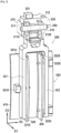
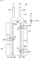
- FIG. 1 represents support tooling 100 for loading porous preforms intended to be infiltrated by a molten metal in accordance with one embodiment of the invention.
- the support tool 100 comprises a rack 200 comprising two suspension bars 210 and 220 each extending longitudinally in a first direction D1.
- the suspension bars 210 and 220 are fixed to a frame 230 by clamping members 231 so as to be kept spaced from one another in a second direction D2 perpendicular to the first direction D1.
- THE frame 230 is fixed at its central part to an interface rod 240 intended to be connected to a mass measuring device of an oven as explained below.
- the support tooling 100 further comprises several supports 300 each intended to maintain a porous preform 400 during its infiltration with a molten metal (a single support 300 is shown on the figure 1 ).
- Each support 300 comprises a first part 310 intended to be connected to one of the suspension bars by a sliding connection in a third direction D3 perpendicular to the first and second directions D1 and D2 and a second part 320 extending from the first part 310 and comprising support elements capable of maintaining a porous preform by point or linear contact. More precisely, in the example described here, the first part 310 is formed here of a first ear 311 comprising an oblong hole 3110 and a second ear 312 comprising an oblong hole 3120.
- each suspension bar 210, 220 comprises on its upper part several notches 211 and 221 respectively in the shape of a V in which the suspension axes 250 are intended to rest.
- each suspension bar 210, 220 comprises grooves 212 and 222 respectively present at least on one side edge of each bar.
- Each groove 212, 222 extends in the third direction D3 and has a width slightly greater than the width of the ear 311 or 312 intended to be housed in one of these grooves.
- the grooves 212 and 222 make it possible to block the rotation of the supports 300 when they are mounted on the suspension bars while allowing translational movement of these supports in the third direction D3.
- the second part 320 of each support 300 comprises two longitudinal arms 321 and 322 extending in the third direction D3, each arm comprising one or more clamping members capable of cooperating with orifices present on a preform porous.
- the longitudinal arm 321 is provided with a first centering screw 3210 cooperating with a first centering orifice 3211 present on the arm 321, the centering screw 3210 comprising a thread cooperating with a tapping provided in the centering orifice 3211.
- the longitudinal arm 322 is provided with a second and a third centering screw 3220 and 3221 cooperating respectively with a second and a third centering orifices 3222 and 3223 present on the arm 322, the centering screws centering 3220 and 3221 comprising a thread cooperating with a tapping provided in the centering orifices 3222 and 3223.
- Each support 300 is loaded with a porous preform 400.
- the preforms 400 correspond to preforms of turbine ring sectors, for example a high pressure turbine ring made of ceramic matrix composite (CMC) material. aeronautical engine. The production of a turbine ring in CMC material by assembling a plurality of ring sectors is described in particular in the document US 2018/0142572 .
- Each porous preform 400 has a shape close to that of the ring sector to be produced.
- Each preform 400 has a section substantially in the shape of an inverted ⁇ with an annular base 410 whose internal face is intended to define the gas flow path in the turbine.
- Tabs 420 and 430 extend from the external face of the annular base 410, the tabs making it possible to connect the ring sectors to a ring support structure as described in particular in the document US 2018/0142572 .
- ceramic fiber yarns can be used, for example SiC fiber yarns such as those marketed by the Japanese company Nippon Carbon under the name "Hi-Nicalon S", or SiC fiber yarns. carbon.
- the preform is preferably produced by three-dimensional weaving, or multilayer weaving with the provision of unbinding zones making it possible to separate the parts of preforms corresponding to the tabs 420 and 410.
- the weave can be interlock type, as shown.
- Other three-dimensional or multi-layer weave weaves can be used, for example multi-canvas or multi-satin weaves.
- the blank After weaving, the blank is shaped to obtain a ring sector preform which is consolidated by chemical gas infiltration (CVI) of a ceramic matrix phase in order to be able to maintain its shape and form a porous preform 400.
- CVI chemical gas infiltration
- the porous preforms 400 are densified by infiltration with liquid silicon (“Melt Infiltration”).
- each porous preform 400 is placed on a support 300 by placing the tabs 420 and 430 between the two longitudinal arms 321 and 322 of the support 300 and then tightening the centering screws 3210, 3220 and 3221 until the The free end of each of these screws penetrates respectively into orifices 421, 431 and 432 present on the tabs 420 and 430 ( figures 3 And 4 ).
- the centering screws allow the vertical suspension of the porous preforms 400 through the orifices 421, 431 and 432, and this with minimum contact (linear or even punctual).
- the longitudinal arms 321 and 322 of the support 300 each respectively comprise on their surface facing the porous preforms 400 bosses 3214, 3215 and 3224, 3225 which make it possible to limit the horizontal movements of the preforms, and this with a contact minimum (linear or even punctual).
- each support 300 is mounted on one of the suspension bars by placing the two ears 311 and 312 on one side and the other of the bar and by inserting a suspension axis 250 into the oblong holes 3110 and 3120 of the ears 311 and 312 as explained previously.
- the support tooling of the invention can support a variable number of porous preforms.
- the support tooling 100 described here can support up to eight porous preforms 400 as illustrated in the Figure 5 .
- it can support a greater or lesser number of porous preforms.
- care will be taken to have an equivalent number of porous preforms and a distribution symmetrical of it on each suspension bar in order to balance the support tools and not disturb the mass measurement during infiltration.
- FIG. 6 shows a sectional view of a furnace 1 according to an embodiment of the invention which can be used in an infiltration process according to the invention.
- the oven 1 comprises a hermetic enclosure 2 inside which are present a crucible 4 having an internal volume containing a molten metal 6, and support tooling 100 comprising a plurality of supports 300 each loaded with a porous preform 400 as described above.
- the crucible 4 may be made of a ceramic material.
- the molten metal 6 can for example be silicon or a silicon alloy.
- the oven 1 is here provided with an induction heating system 10 comprising an induction coil 12 and a susceptor 14 which are arranged around the crucible 4 and the preform 8 in the enclosure 2 of the oven 1.
- the heating system heating further comprises, in known manner, a high frequency generator 16 connected to the coil 12 so as to generate a variable magnetic field using the coil 12.
- the susceptor 14 can for example be a graphite cylinder.
- the oven 1 can also be provided with a vacuum pump 18 in fluid communication with the interior of the enclosure 2, so as to carry out the vacuum infiltration process. Note that another type of oven than that illustrated can be used, in particular the oven can include a resistive heating system instead of an inductive system.
- the oven 1 comprises a device for measuring the mass of the preforms 400 corresponding here to a scale 20 of the load cell type, to which the support tooling 400 is suspended by means of the interface rod 240 of the support tooling 100.
- the balance 20 is located outside the enclosure 2 of the oven 1, above the enclosure 2.
- other mass measuring devices can be used without leaving the context of the present invention.
- the oven 1 further comprises a movement device comprising here a cylinder 24 having a rod 26 on which the crucible 4 is mounted.
- the cylinder 24 is located outside the enclosure 2 of the oven 1, at below the enclosure 2.
- the cylinder 20 makes it possible to move the crucible 4 with a vertical translation movement inside the enclosure 2 of the oven 1, in particular towards the porous preforms 400 present on the support tooling 100.
- the crucible 4 is mobile in vertical translation in enclosure 2.
- the crucible can be fixedly mounted in the oven, and the preform can be movable in vertical translation.
- the oven 1 also includes a control system 28 of the relative position between the preforms and the crucible, which is configured to control the cylinder 24 as a function of the evolution of the mass of the preforms 400 as measured by the balance 20.
- This control system 28 can be for example a PLC or a computer equipped with an input/output acquisition card.
- the control system 28 can receive electrical signals from the scale 20 as input, and send control signals as output to the cylinder 24.
- the infiltration of the porous preforms 400 is carried out by bringing said preforms into contact with the molten metal 6 which can for example be silicon or a silicon alloy, the molten metal infiltrating the porosity of the preforms by capillarity.
- the contacting can be direct, that is to say the preforms are directly dipped in the bath of molten metal, or indirect by placing the preforms in contact with one or more drains (not shown on the figure).
- Figure 6 themselves in contact with the bath of molten metal which is then conveyed to the preforms by capillary action.
- the control of the infiltration of the preforms by the molten metal is carried out by controlling the cylinder 24.
- the infiltration of the preforms 400 by the molten metal 6 occurs. ends when the balance 20 measures a predetermined mass gain corresponding to the level of densification desired for the preforms.
- parts, here ring sectors, made of CMC material comprising a fibrous reinforcement densified by a matrix are obtained.
- the support 500 differs from the support 300 described previously at the level of the second part of the support. More precisely, the support 500 comprises, like the support 300 already described, a first part 510 formed of a first ear 511 comprising an oblong hole 5110 and a second ear 512 comprising an oblong hole 5120.
- Each support 500 can be mounted on a suspension bar of a support tool, such as the suspension bar 210 of the support tool 100 described above, in placing the two ears 511 and 512 on one side and the other of the bar and inserting a suspension axis 250 into the oblong holes 5110 and 5120 of the ears 511 and 512 as already described ( figure 8 ).
- the support 500 further comprises a second part 520 extending from the first part 510.
- the second part 520 is intended to support a porous preform, corresponding here to a turbine ring sector preform, for example a ring of high pressure turbine in ceramic matrix composite (CMC) material of aeronautical engine.
- CMC ceramic matrix composite
- the production of a turbine ring in CMC material by assembling a plurality of ring sectors is described in particular in the document US 2018/0142572 .
- Each porous preform has a shape close to that of the ring sector to be produced and has a section substantially in the shape of an inverted ⁇ with an annular base whose internal face is intended to define the flow path of gas flow in the turbine and legs and extending from the external face of the annular base.
- the second part 520 of each support 500 comprises a longitudinal arm 521 extending in the third direction D3 and two transverse arms 522 and 523 extending on each side of the longitudinal arm 521 in the direction D2.
- a first projection 5220 is mounted on the transverse arm 522 by means of a clamping screw 5222, the projection 5220 extending from the arm 522 in the direction D1 and having a free end 5221.
- a second projection 5230 is mounted on the transverse arm 523 by means of a clamping screw 5232, the projection 5230 extending from the arm 523 in the direction D1 and having a free end 5231.
- each porous preform is placed on a support 500 by engaging the free ends 5221 and 5231 of the projections 5220 and 5230 respectively in the notches 611 and 612, the preform then being held in suspension by the free ends 5221 and 5231 ( figures 8 And 9 ).
- Removable adjustment shims 5223 and 5233 can be used to adjust the air gap of the projections 5220 and 5230 relative to the spacing between the notches 611 and 612 in the direction D2.
- There suspension of the preforms by the projections 5220 and 5230 do not require the presence of orifices on the legs of the preforms, such as the orifices 421, 431 and 432 described previously, which makes it possible to avoid machining operations of orifices in the preforms when these are not useful for fixing or maintaining the ring sectors.
- the support 500 may include an anti-tilt screw 524 whose threaded rod 5241 is screwed into an orifice 525 present on the upper part of the longitudinal arm 521.
- the head 5240 of the anti-tilt screw 524 blocks the tilting of the preform ( Figure 9 ).
- the support 500 can include a fixed stop 526 present on the upper part of the longitudinal arm 521 in order to limit by point contact the translation of the porous preform in direction D1.
- the support 500 can include an adjustable stop 527 present on the lower part of the longitudinal arm 521 in order to limit by point contact the rotation of the porous preform on the projections and thus position the preform according to a horizontal plane parallel to direction D3 during operations of infiltration of preforms with molten metal.
- the adjustable stop 527 cooperates by screwing with an orifice 528 present on the lower part of the longitudinal arm 521.
- the support 500 makes it possible to reliably maintain a porous preform with only a few point contact points, which makes it possible to optimize the infiltration of the preform by a molten metal, while facilitating and securing loading the preforms onto the support tooling.
- the support tooling according to the invention makes it possible to form loads each comprising a plurality of porous preforms thus allowing batch processing of said preforms in an infiltration oven.
Landscapes
- Engineering & Computer Science (AREA)
- Chemical & Material Sciences (AREA)
- Mechanical Engineering (AREA)
- General Engineering & Computer Science (AREA)
- Materials Engineering (AREA)
- Organic Chemistry (AREA)
- Metallurgy (AREA)
- Ceramic Engineering (AREA)
- Chemical Kinetics & Catalysis (AREA)
- Inorganic Chemistry (AREA)
- Structural Engineering (AREA)
- Furnace Charging Or Discharging (AREA)
- Manufacture Of Alloys Or Alloy Compounds (AREA)
- Reinforced Plastic Materials (AREA)
- Blow-Moulding Or Thermoforming Of Plastics Or The Like (AREA)
Claims (10)
- Haltewerkzeug (100) für poröse Vorformen (400), die dazu vorgesehen sind, mit einer Metallschmelze durchdrungen zu werden, wobei das Werkzeug umfasst:- einen Ständer (200), der mindestens zwei Aufhängungsstäbe (210, 220) umfasst, die sich jeweils in Längsrichtung in einer ersten Richtung (D1) erstrecken, wobei die mindestens zwei Aufhängungsstäbe in einer zweiten Richtung (D2) senkrecht zu der ersten Richtung voneinander beabstandet gehalten werden,- mehrere Halterungen (300) für poröse Vorformen, die abnehmbar an den Aufhängungsstäben (210, 220) angebracht sind, wobei jede Halterung einen ersten Abschnitt (310), der mit einem der Aufhängungsstäbe durch eine Gleitverbindung in einer dritten Richtung (D3) senkrecht zu der ersten und der zweiten Richtung (D1, D2) verbunden ist, und einen zweiten Abschnitt (320), der sich von dem ersten Abschnitt aus erstreckt und Halteelemente umfasst, die geeignet sind, eine poröse Vorform durch Punktkontakt oder linearen Kontakt zu halten, umfasst.
- Werkzeug nach Anspruch 1, wobei der erste Abschnitt (310) jeder Halterung für poröse Vorformen zwei sich in der dritten Richtung (D3) erstreckende Ansätze (311, 312) beinhaltet, wobei mindestens ein Ansatz (311) in eine Nut (212), die an einem der Aufhängungsstäbe (210) vorhanden ist, eingreift und sich in der dritten Richtung erstreckt, wobei jeder Ansatz (311; 312) an seinem freien Ende ein Langloch (3110; 3120) beinhaltet, in dem ein Aufhängungsbolzen (250) aufgenommen ist, der auf einem der Aufhängungsstäbe aufliegt.
- Werkzeug nach Anspruch 2, wobei jeder Aufhängungsstab (210; 220) eine oder mehrere V-förmige Kerben (211; 221) umfasst, die geeignet sind, einen Aufhängungsbolzen aufzunehmen.
- Werkzeug nach einem der Ansprüche 1 bis 3, wobei der zweite Abschnitt (320) jeder Halterung (300) für poröse Vorformen zwei Längsarme (321, 322) umfasst, die sich in der dritten Richtung erstrecken, wobei jeder Arm ein oder mehrere Klemmelemente (3210, 3220, 3221) beinhaltet, die geeignet sind, mit Öffnungen (421, 431, 432) zusammenzuwirken, die in einer porösen Vorform (400) vorhanden sind.
- Werkzeug nach Anspruch 4, wobei jeder Längsarm (321; 322) des zweiten Abschnitts (320) jeder Halterung (300) für poröse Vorformen eine oder mehrere Erhebungen (3214, 3215, 3224, 3225) auf seiner dem anderen Arm zugewandten Seite beinhaltet.
- Werkzeug nach einem der Ansprüche 1 bis 5, wobei der zweite Abschnitt (520) jeder Halterung (500) für poröse Vorformen zwei Querarme (522, 523) umfasst, die sich in der zweiten Richtung (D2) erstrecken, wobei jeder Querarm einen Vorsprung (5220; 5230) beinhaltet, der sich in der ersten Richtung (D1) erstreckt, wobei jeder Vorsprung (5220; 5230) geeignet ist, mit einer Kerbe (611; 612) zusammenzuwirken, die in der porösen Vorform vorhanden ist.
- Werkzeug nach Anspruch 6, wobei der zweite Abschnitt (520) jeder Halterung für poröse Vorformen eine Anti-Kipp-Schraube (524) umfasst.
- Werkzeug nach Anspruch 6 oder 7, wobei der zweite Abschnitt (520) jeder Halterung (500) für poröse Vorformen einen verstellbaren Anschlag (528) umfasst, der in dem unteren Abschnitt des zweiten Abschnitts vorhanden ist.
- Ofen (1), der dazu vorgesehen ist, zum Durchdringen von porösen Vorformen (8) mit einer Metallschmelze (6) verwendet zu werden, wobei der Ofen mindestens umfasst:- ein Haltewerkzeug (100) nach einem der Ansprüche 1 bis 8, wobei mindestens mehrere Halterungen der mehreren Halterungen des Werkzeugs mit einer porösen Vorform (400) beladen sind,- eine Massemessvorrichtung (20), mit der das Haltewerkzeug verbunden ist,- einen Schmelztiegel (4), der ein Innenvolumen aufweist, das dazu vorgesehen ist, eine Metallschmelze (6) aufzunehmen, und- eine Bewegungsvorrichtung (24), die geeignet ist, den Schmelztiegel oder das Haltewerkzeug im Verhältnis zueinander zwischen einer ersten Konfiguration, in der sich die porösen Vorformen (400) außerhalb des Innenvolumens des Schmelztiegels (4) oder in einem Abstand zu einem oder mehreren Abflüssen in Verbindung mit dem Innenvolumen des Schmelztiegels befinden, und einer zweiten Konfiguration, in der sich die porösen Vorformen (400) zumindest teilweise in dem Innenvolumen oder in Kontakt mit dem oder den Abflüssen befinden, zu bewegen.
- Verfahren zum Durchdringen mehrerer poröser Vorformen (400) mit einer Metallschmelze, wobei das Durchdringen in einem Ofen nach Anspruch 9 durchgeführt wird, wobei das Verfahren umfasst:- Laden mehrerer poröser Vorformen (400) in ein Haltewerkzeug (100) nach einem der Ansprüche 1 bis 8,- Inkontaktbringen der porösen Vorformen (400) mit der Metallschmelze (6) direkt oder über einen oder mehrere Abflüsse,- Durchdringen der porösen Vorformen (400) mit der Metallschmelze (6),- Messen der Masse der porösen Vorformen während des Durchdringens und- Lösen der porösen Vorformen von der Metallschmelze, wenn die gemessene Masse der Vorformen einen vorbestimmten Wert erreicht.
Applications Claiming Priority (2)
| Application Number | Priority Date | Filing Date | Title |
|---|---|---|---|
| FR1902822A FR3093938B1 (fr) | 2019-03-19 | 2019-03-19 | Outillage de support pour préformes poreuses à infiltrer et four utilisant un tel outillage |
| PCT/FR2020/050522 WO2020188196A1 (fr) | 2019-03-19 | 2020-03-12 | Outillage de support pour preformes poreuses a infiltrer et four utilisant un tel outillage |
Publications (2)
| Publication Number | Publication Date |
|---|---|
| EP3941660A1 EP3941660A1 (de) | 2022-01-26 |
| EP3941660B1 true EP3941660B1 (de) | 2023-11-08 |
Family
ID=67441380
Family Applications (1)
| Application Number | Title | Priority Date | Filing Date |
|---|---|---|---|
| EP20725888.0A Active EP3941660B1 (de) | 2019-03-19 | 2020-03-12 | Stützwerkzeug für poröse vorformen und ofen mit einem solchen werkzeug |
Country Status (5)
| Country | Link |
|---|---|
| US (1) | US12098884B2 (de) |
| EP (1) | EP3941660B1 (de) |
| CN (1) | CN113574341B (de) |
| FR (1) | FR3093938B1 (de) |
| WO (1) | WO2020188196A1 (de) |
Families Citing this family (3)
| Publication number | Priority date | Publication date | Assignee | Title |
|---|---|---|---|---|
| FR3093938B1 (fr) * | 2019-03-19 | 2021-02-26 | Safran Ceram | Outillage de support pour préformes poreuses à infiltrer et four utilisant un tel outillage |
| US12392037B2 (en) | 2022-10-21 | 2025-08-19 | Rtx Corporation | Floating tooling assembly for chemical vapor infiltration |
| FR3146821A1 (fr) * | 2023-03-21 | 2024-09-27 | Safran Ceramics | Procédé de fabrication d’un secteur d’anneau de turbine |
Family Cites Families (14)
| Publication number | Priority date | Publication date | Assignee | Title |
|---|---|---|---|---|
| US7415844B2 (en) * | 2001-06-25 | 2008-08-26 | Prysmian Cavi E Sistemi Energia S.R.L. | Device for manufacturing a preform for optical fibres through chemical deposition |
| DE10350273B4 (de) * | 2003-10-28 | 2013-01-03 | Robert Bosch Gmbh | Verfahren zur Herstellung von preformbasierten Verbundwerkstoffen |
| CN1329559C (zh) | 2004-08-10 | 2007-08-01 | 山东大学 | 一种用于近化学计量比铌酸锂晶体生长的悬挂坩埚及生长方法 |
| FR2887601B1 (fr) | 2005-06-24 | 2007-10-05 | Snecma Moteurs Sa | Piece mecanique et procede de fabrication d'une telle piece |
| CN102145895B (zh) | 2011-05-16 | 2012-10-03 | 大连隆田科技有限公司 | 一种浅熔池真空熔炼提纯多晶硅的方法及设备 |
| CN102912416A (zh) | 2012-10-25 | 2013-02-06 | 宁夏日晶新能源装备股份有限公司 | 新型多晶炉加热装置 |
| CN103966666B (zh) | 2014-05-20 | 2016-06-15 | 江苏盎华光伏工程技术研究中心有限公司 | 多晶硅装料设备及其控制方法 |
| CN204265893U (zh) | 2014-11-13 | 2015-04-15 | 宁晋晶兴电子材料有限公司 | 一种单晶炉投料用表皮料吊具 |
| CN204625838U (zh) | 2015-04-30 | 2015-09-09 | 邢台晶龙电子材料有限公司 | 一种单晶炉二次加料自锁吊具 |
| FR3036433B1 (fr) | 2015-05-22 | 2019-09-13 | Safran Ceramics | Ensemble d'anneau de turbine avec maintien par crabotage |
| CN205270846U (zh) * | 2015-08-18 | 2016-06-01 | 河北丰德机械制造有限公司 | 一种阀门铸造用浇包转运支撑架 |
| FR3063724B1 (fr) * | 2017-03-08 | 2022-06-24 | Safran Ceram | Procede d'infiltration d'une preforme poreuse et four associe |
| CN107673187A (zh) * | 2017-11-07 | 2018-02-09 | 河南恒远恒山工业有限公司 | 一种叉车式起重机 |
| FR3093938B1 (fr) * | 2019-03-19 | 2021-02-26 | Safran Ceram | Outillage de support pour préformes poreuses à infiltrer et four utilisant un tel outillage |
-
2019
- 2019-03-19 FR FR1902822A patent/FR3093938B1/fr active Active
-
2020
- 2020-03-12 US US17/436,800 patent/US12098884B2/en active Active
- 2020-03-12 WO PCT/FR2020/050522 patent/WO2020188196A1/fr not_active Ceased
- 2020-03-12 EP EP20725888.0A patent/EP3941660B1/de active Active
- 2020-03-12 CN CN202080021703.6A patent/CN113574341B/zh active Active
Also Published As
| Publication number | Publication date |
|---|---|
| CN113574341B (zh) | 2023-10-27 |
| FR3093938B1 (fr) | 2021-02-26 |
| US12098884B2 (en) | 2024-09-24 |
| CN113574341A (zh) | 2021-10-29 |
| FR3093938A1 (fr) | 2020-09-25 |
| EP3941660A1 (de) | 2022-01-26 |
| WO2020188196A1 (fr) | 2020-09-24 |
| US20220170143A1 (en) | 2022-06-02 |
Similar Documents
| Publication | Publication Date | Title |
|---|---|---|
| WO2020188196A1 (fr) | Outillage de support pour preformes poreuses a infiltrer et four utilisant un tel outillage | |
| EP3762347B1 (de) | Verfahren zur infiltration eines porösen vorförmlings | |
| EP1042517B1 (de) | Anordnung zur ladung von gutträgern für thermische ofenbehandlungen | |
| EP2828413B1 (de) | Haltewerkzeug zur wärmebehandlung von metallteilen | |
| EP2970030B1 (de) | Schmelzinfiltrationsvorrichtung und verfahren für metallschmelzekontrolle | |
| FR3021671A1 (fr) | Conformateur pour la consolidation et/ou la densification en phase gazeuse d'une preforme fibreuse | |
| EP3346030A1 (de) | Anlage für die herstellung eines teils durch umsetzung eines bridgman-verfahrens | |
| EP0922779B1 (de) | Metallmatrixverbundkörper mit hoher Steifigkeit und hoher Stabilität in Längsrichtung | |
| FR3136235A1 (fr) | Procédé de fabrication d’une pièce en matériau composite | |
| FR3089851A1 (fr) | Chambre de fabrication pour une machine de fabrication additive | |
| WO2024194562A1 (fr) | Procede de fabrication d'un secteur d'anneau de turbine | |
| FR3055624A1 (fr) | Preforme fibreuse pour fabriquer une piece en materiau composite et procede associe | |
| EP3850195B1 (de) | Abnehmbare trägerschnittstelle für eine ringförmige turbomaschine | |
| FR2891896A1 (fr) | Procede d'instrumentation d'un element en materiau composite a matrice ceramique | |
| EP4392330B1 (de) | Thermisch regulierte raumausrüstung mit thermisch isolierender mechanischer stütze | |
| FR3050391A1 (fr) | Procede de fabrication additive et piece obtenue par un tel procede | |
| US4708478A (en) | Tube cell for atomic absorption spectrophotometry | |
| WO2020053535A1 (fr) | Installation de fabrication additive perfectionnee | |
| FR3055625A1 (fr) | Preforme fibreuse pour fabriquer une piece en materiau composite et procede associe | |
| FR3154725A1 (fr) | Procédé de fabrication d’une pièce en matériau composite à matrice hybride | |
| FR3053266A1 (fr) | Machine et procede pour le decochage de grappes de fonderie | |
| FR2974420A1 (fr) | Vanne de flux et procede de fabrication d'une telle vanne | |
| FR2948633A1 (fr) | Poutre de suspension annulaire de turbomoteur a la structure d'un aeronef |
Legal Events
| Date | Code | Title | Description |
|---|---|---|---|
| STAA | Information on the status of an ep patent application or granted ep patent |
Free format text: STATUS: UNKNOWN |
|
| STAA | Information on the status of an ep patent application or granted ep patent |
Free format text: STATUS: THE INTERNATIONAL PUBLICATION HAS BEEN MADE |
|
| PUAI | Public reference made under article 153(3) epc to a published international application that has entered the european phase |
Free format text: ORIGINAL CODE: 0009012 |
|
| STAA | Information on the status of an ep patent application or granted ep patent |
Free format text: STATUS: REQUEST FOR EXAMINATION WAS MADE |
|
| 17P | Request for examination filed |
Effective date: 20210915 |
|
| AK | Designated contracting states |
Kind code of ref document: A1 Designated state(s): AL AT BE BG CH CY CZ DE DK EE ES FI FR GB GR HR HU IE IS IT LI LT LU LV MC MK MT NL NO PL PT RO RS SE SI SK SM TR |
|
| DAV | Request for validation of the european patent (deleted) | ||
| DAX | Request for extension of the european patent (deleted) | ||
| GRAP | Despatch of communication of intention to grant a patent |
Free format text: ORIGINAL CODE: EPIDOSNIGR1 |
|
| STAA | Information on the status of an ep patent application or granted ep patent |
Free format text: STATUS: GRANT OF PATENT IS INTENDED |
|
| INTG | Intention to grant announced |
Effective date: 20230526 |
|
| GRAS | Grant fee paid |
Free format text: ORIGINAL CODE: EPIDOSNIGR3 |
|
| GRAA | (expected) grant |
Free format text: ORIGINAL CODE: 0009210 |
|
| STAA | Information on the status of an ep patent application or granted ep patent |
Free format text: STATUS: THE PATENT HAS BEEN GRANTED |
|
| AK | Designated contracting states |
Kind code of ref document: B1 Designated state(s): AL AT BE BG CH CY CZ DE DK EE ES FI FR GB GR HR HU IE IS IT LI LT LU LV MC MK MT NL NO PL PT RO RS SE SI SK SM TR |
|
| REG | Reference to a national code |
Ref country code: GB Ref legal event code: FG4D Free format text: NOT ENGLISH |
|
| REG | Reference to a national code |
Ref country code: CH Ref legal event code: EP |
|
| REG | Reference to a national code |
Ref country code: DE Ref legal event code: R096 Ref document number: 602020020702 Country of ref document: DE |
|
| REG | Reference to a national code |
Ref country code: IE Ref legal event code: FG4D Free format text: LANGUAGE OF EP DOCUMENT: FRENCH |
|
| REG | Reference to a national code |
Ref country code: LT Ref legal event code: MG9D |
|
| REG | Reference to a national code |
Ref country code: NL Ref legal event code: MP Effective date: 20231108 |
|
| PG25 | Lapsed in a contracting state [announced via postgrant information from national office to epo] |
Ref country code: GR Free format text: LAPSE BECAUSE OF FAILURE TO SUBMIT A TRANSLATION OF THE DESCRIPTION OR TO PAY THE FEE WITHIN THE PRESCRIBED TIME-LIMIT Effective date: 20240209 |
|
| PG25 | Lapsed in a contracting state [announced via postgrant information from national office to epo] |
Ref country code: IS Free format text: LAPSE BECAUSE OF FAILURE TO SUBMIT A TRANSLATION OF THE DESCRIPTION OR TO PAY THE FEE WITHIN THE PRESCRIBED TIME-LIMIT Effective date: 20240308 |
|
| PG25 | Lapsed in a contracting state [announced via postgrant information from national office to epo] |
Ref country code: LT Free format text: LAPSE BECAUSE OF FAILURE TO SUBMIT A TRANSLATION OF THE DESCRIPTION OR TO PAY THE FEE WITHIN THE PRESCRIBED TIME-LIMIT Effective date: 20231108 |
|
| REG | Reference to a national code |
Ref country code: AT Ref legal event code: MK05 Ref document number: 1629176 Country of ref document: AT Kind code of ref document: T Effective date: 20231108 |
|
| PG25 | Lapsed in a contracting state [announced via postgrant information from national office to epo] |
Ref country code: NL Free format text: LAPSE BECAUSE OF FAILURE TO SUBMIT A TRANSLATION OF THE DESCRIPTION OR TO PAY THE FEE WITHIN THE PRESCRIBED TIME-LIMIT Effective date: 20231108 |
|
| PG25 | Lapsed in a contracting state [announced via postgrant information from national office to epo] |
Ref country code: AT Free format text: LAPSE BECAUSE OF FAILURE TO SUBMIT A TRANSLATION OF THE DESCRIPTION OR TO PAY THE FEE WITHIN THE PRESCRIBED TIME-LIMIT Effective date: 20231108 |
|
| PG25 | Lapsed in a contracting state [announced via postgrant information from national office to epo] |
Ref country code: ES Free format text: LAPSE BECAUSE OF FAILURE TO SUBMIT A TRANSLATION OF THE DESCRIPTION OR TO PAY THE FEE WITHIN THE PRESCRIBED TIME-LIMIT Effective date: 20231108 |
|
| PG25 | Lapsed in a contracting state [announced via postgrant information from national office to epo] |
Ref country code: NL Free format text: LAPSE BECAUSE OF FAILURE TO SUBMIT A TRANSLATION OF THE DESCRIPTION OR TO PAY THE FEE WITHIN THE PRESCRIBED TIME-LIMIT Effective date: 20231108 Ref country code: LT Free format text: LAPSE BECAUSE OF FAILURE TO SUBMIT A TRANSLATION OF THE DESCRIPTION OR TO PAY THE FEE WITHIN THE PRESCRIBED TIME-LIMIT Effective date: 20231108 Ref country code: IS Free format text: LAPSE BECAUSE OF FAILURE TO SUBMIT A TRANSLATION OF THE DESCRIPTION OR TO PAY THE FEE WITHIN THE PRESCRIBED TIME-LIMIT Effective date: 20240308 Ref country code: GR Free format text: LAPSE BECAUSE OF FAILURE TO SUBMIT A TRANSLATION OF THE DESCRIPTION OR TO PAY THE FEE WITHIN THE PRESCRIBED TIME-LIMIT Effective date: 20240209 Ref country code: ES Free format text: LAPSE BECAUSE OF FAILURE TO SUBMIT A TRANSLATION OF THE DESCRIPTION OR TO PAY THE FEE WITHIN THE PRESCRIBED TIME-LIMIT Effective date: 20231108 Ref country code: BG Free format text: LAPSE BECAUSE OF FAILURE TO SUBMIT A TRANSLATION OF THE DESCRIPTION OR TO PAY THE FEE WITHIN THE PRESCRIBED TIME-LIMIT Effective date: 20240208 Ref country code: AT Free format text: LAPSE BECAUSE OF FAILURE TO SUBMIT A TRANSLATION OF THE DESCRIPTION OR TO PAY THE FEE WITHIN THE PRESCRIBED TIME-LIMIT Effective date: 20231108 Ref country code: PT Free format text: LAPSE BECAUSE OF FAILURE TO SUBMIT A TRANSLATION OF THE DESCRIPTION OR TO PAY THE FEE WITHIN THE PRESCRIBED TIME-LIMIT Effective date: 20240308 |
|
| PG25 | Lapsed in a contracting state [announced via postgrant information from national office to epo] |
Ref country code: SE Free format text: LAPSE BECAUSE OF FAILURE TO SUBMIT A TRANSLATION OF THE DESCRIPTION OR TO PAY THE FEE WITHIN THE PRESCRIBED TIME-LIMIT Effective date: 20231108 Ref country code: RS Free format text: LAPSE BECAUSE OF FAILURE TO SUBMIT A TRANSLATION OF THE DESCRIPTION OR TO PAY THE FEE WITHIN THE PRESCRIBED TIME-LIMIT Effective date: 20231108 Ref country code: PL Free format text: LAPSE BECAUSE OF FAILURE TO SUBMIT A TRANSLATION OF THE DESCRIPTION OR TO PAY THE FEE WITHIN THE PRESCRIBED TIME-LIMIT Effective date: 20231108 Ref country code: NO Free format text: LAPSE BECAUSE OF FAILURE TO SUBMIT A TRANSLATION OF THE DESCRIPTION OR TO PAY THE FEE WITHIN THE PRESCRIBED TIME-LIMIT Effective date: 20240208 Ref country code: LV Free format text: LAPSE BECAUSE OF FAILURE TO SUBMIT A TRANSLATION OF THE DESCRIPTION OR TO PAY THE FEE WITHIN THE PRESCRIBED TIME-LIMIT Effective date: 20231108 Ref country code: HR Free format text: LAPSE BECAUSE OF FAILURE TO SUBMIT A TRANSLATION OF THE DESCRIPTION OR TO PAY THE FEE WITHIN THE PRESCRIBED TIME-LIMIT Effective date: 20231108 |
|
| PG25 | Lapsed in a contracting state [announced via postgrant information from national office to epo] |
Ref country code: DK Free format text: LAPSE BECAUSE OF FAILURE TO SUBMIT A TRANSLATION OF THE DESCRIPTION OR TO PAY THE FEE WITHIN THE PRESCRIBED TIME-LIMIT Effective date: 20231108 |
|
| PG25 | Lapsed in a contracting state [announced via postgrant information from national office to epo] |
Ref country code: CZ Free format text: LAPSE BECAUSE OF FAILURE TO SUBMIT A TRANSLATION OF THE DESCRIPTION OR TO PAY THE FEE WITHIN THE PRESCRIBED TIME-LIMIT Effective date: 20231108 |
|
| PG25 | Lapsed in a contracting state [announced via postgrant information from national office to epo] |
Ref country code: SK Free format text: LAPSE BECAUSE OF FAILURE TO SUBMIT A TRANSLATION OF THE DESCRIPTION OR TO PAY THE FEE WITHIN THE PRESCRIBED TIME-LIMIT Effective date: 20231108 |
|
| PG25 | Lapsed in a contracting state [announced via postgrant information from national office to epo] |
Ref country code: SM Free format text: LAPSE BECAUSE OF FAILURE TO SUBMIT A TRANSLATION OF THE DESCRIPTION OR TO PAY THE FEE WITHIN THE PRESCRIBED TIME-LIMIT Effective date: 20231108 Ref country code: SK Free format text: LAPSE BECAUSE OF FAILURE TO SUBMIT A TRANSLATION OF THE DESCRIPTION OR TO PAY THE FEE WITHIN THE PRESCRIBED TIME-LIMIT Effective date: 20231108 Ref country code: RO Free format text: LAPSE BECAUSE OF FAILURE TO SUBMIT A TRANSLATION OF THE DESCRIPTION OR TO PAY THE FEE WITHIN THE PRESCRIBED TIME-LIMIT Effective date: 20231108 Ref country code: IT Free format text: LAPSE BECAUSE OF FAILURE TO SUBMIT A TRANSLATION OF THE DESCRIPTION OR TO PAY THE FEE WITHIN THE PRESCRIBED TIME-LIMIT Effective date: 20231108 Ref country code: EE Free format text: LAPSE BECAUSE OF FAILURE TO SUBMIT A TRANSLATION OF THE DESCRIPTION OR TO PAY THE FEE WITHIN THE PRESCRIBED TIME-LIMIT Effective date: 20231108 Ref country code: DK Free format text: LAPSE BECAUSE OF FAILURE TO SUBMIT A TRANSLATION OF THE DESCRIPTION OR TO PAY THE FEE WITHIN THE PRESCRIBED TIME-LIMIT Effective date: 20231108 Ref country code: CZ Free format text: LAPSE BECAUSE OF FAILURE TO SUBMIT A TRANSLATION OF THE DESCRIPTION OR TO PAY THE FEE WITHIN THE PRESCRIBED TIME-LIMIT Effective date: 20231108 |
|
| REG | Reference to a national code |
Ref country code: DE Ref legal event code: R097 Ref document number: 602020020702 Country of ref document: DE |
|
| PLBE | No opposition filed within time limit |
Free format text: ORIGINAL CODE: 0009261 |
|
| STAA | Information on the status of an ep patent application or granted ep patent |
Free format text: STATUS: NO OPPOSITION FILED WITHIN TIME LIMIT |
|
| 26N | No opposition filed |
Effective date: 20240809 |
|
| PG25 | Lapsed in a contracting state [announced via postgrant information from national office to epo] |
Ref country code: SI Free format text: LAPSE BECAUSE OF FAILURE TO SUBMIT A TRANSLATION OF THE DESCRIPTION OR TO PAY THE FEE WITHIN THE PRESCRIBED TIME-LIMIT Effective date: 20231108 |
|
| PG25 | Lapsed in a contracting state [announced via postgrant information from national office to epo] |
Ref country code: SI Free format text: LAPSE BECAUSE OF FAILURE TO SUBMIT A TRANSLATION OF THE DESCRIPTION OR TO PAY THE FEE WITHIN THE PRESCRIBED TIME-LIMIT Effective date: 20231108 |
|
| REG | Reference to a national code |
Ref country code: CH Ref legal event code: PL |
|
| PG25 | Lapsed in a contracting state [announced via postgrant information from national office to epo] |
Ref country code: LU Free format text: LAPSE BECAUSE OF NON-PAYMENT OF DUE FEES Effective date: 20240312 |
|
| PG25 | Lapsed in a contracting state [announced via postgrant information from national office to epo] |
Ref country code: MC Free format text: LAPSE BECAUSE OF FAILURE TO SUBMIT A TRANSLATION OF THE DESCRIPTION OR TO PAY THE FEE WITHIN THE PRESCRIBED TIME-LIMIT Effective date: 20231108 |
|
| PG25 | Lapsed in a contracting state [announced via postgrant information from national office to epo] |
Ref country code: MC Free format text: LAPSE BECAUSE OF FAILURE TO SUBMIT A TRANSLATION OF THE DESCRIPTION OR TO PAY THE FEE WITHIN THE PRESCRIBED TIME-LIMIT Effective date: 20231108 Ref country code: LU Free format text: LAPSE BECAUSE OF NON-PAYMENT OF DUE FEES Effective date: 20240312 |
|
| REG | Reference to a national code |
Ref country code: BE Ref legal event code: MM Effective date: 20240331 |
|
| PG25 | Lapsed in a contracting state [announced via postgrant information from national office to epo] |
Ref country code: BE Free format text: LAPSE BECAUSE OF NON-PAYMENT OF DUE FEES Effective date: 20240331 |
|
| PG25 | Lapsed in a contracting state [announced via postgrant information from national office to epo] |
Ref country code: IE Free format text: LAPSE BECAUSE OF NON-PAYMENT OF DUE FEES Effective date: 20240312 |
|
| PG25 | Lapsed in a contracting state [announced via postgrant information from national office to epo] |
Ref country code: IE Free format text: LAPSE BECAUSE OF NON-PAYMENT OF DUE FEES Effective date: 20240312 Ref country code: BE Free format text: LAPSE BECAUSE OF NON-PAYMENT OF DUE FEES Effective date: 20240331 Ref country code: CH Free format text: LAPSE BECAUSE OF NON-PAYMENT OF DUE FEES Effective date: 20240331 |
|
| PG25 | Lapsed in a contracting state [announced via postgrant information from national office to epo] |
Ref country code: CY Free format text: LAPSE BECAUSE OF FAILURE TO SUBMIT A TRANSLATION OF THE DESCRIPTION OR TO PAY THE FEE WITHIN THE PRESCRIBED TIME-LIMIT; INVALID AB INITIO Effective date: 20200312 |
|
| PG25 | Lapsed in a contracting state [announced via postgrant information from national office to epo] |
Ref country code: HU Free format text: LAPSE BECAUSE OF FAILURE TO SUBMIT A TRANSLATION OF THE DESCRIPTION OR TO PAY THE FEE WITHIN THE PRESCRIBED TIME-LIMIT; INVALID AB INITIO Effective date: 20200312 |
|
| PG25 | Lapsed in a contracting state [announced via postgrant information from national office to epo] |
Ref country code: FI Free format text: LAPSE BECAUSE OF FAILURE TO SUBMIT A TRANSLATION OF THE DESCRIPTION OR TO PAY THE FEE WITHIN THE PRESCRIBED TIME-LIMIT Effective date: 20231108 |
|
| PG25 | Lapsed in a contracting state [announced via postgrant information from national office to epo] |
Ref country code: TR Free format text: LAPSE BECAUSE OF FAILURE TO SUBMIT A TRANSLATION OF THE DESCRIPTION OR TO PAY THE FEE WITHIN THE PRESCRIBED TIME-LIMIT Effective date: 20231108 |
|
| PGFP | Annual fee paid to national office [announced via postgrant information from national office to epo] |
Ref country code: GB Payment date: 20260324 Year of fee payment: 7 |
|
| PGFP | Annual fee paid to national office [announced via postgrant information from national office to epo] |
Ref country code: DE Payment date: 20260320 Year of fee payment: 7 |
|
| PGFP | Annual fee paid to national office [announced via postgrant information from national office to epo] |
Ref country code: FR Payment date: 20260318 Year of fee payment: 7 |