EP4392330B1 - Thermisch regulierte raumausrüstung mit thermisch isolierender mechanischer stütze - Google Patents
Thermisch regulierte raumausrüstung mit thermisch isolierender mechanischer stütze Download PDFInfo
- Publication number
- EP4392330B1 EP4392330B1 EP23729803.9A EP23729803A EP4392330B1 EP 4392330 B1 EP4392330 B1 EP 4392330B1 EP 23729803 A EP23729803 A EP 23729803A EP 4392330 B1 EP4392330 B1 EP 4392330B1
- Authority
- EP
- European Patent Office
- Prior art keywords
- interface
- mesh
- mechanical support
- equipment
- support structure
- Prior art date
- Legal status (The legal status is an assumption and is not a legal conclusion. Google has not performed a legal analysis and makes no representation as to the accuracy of the status listed.)
- Active
Links
Images




Classifications
-
- B—PERFORMING OPERATIONS; TRANSPORTING
- B64—AIRCRAFT; AVIATION; COSMONAUTICS
- B64G—COSMONAUTICS; VEHICLES OR EQUIPMENT THEREFOR
- B64G1/00—Cosmonautic vehicles
- B64G1/22—Parts of, or equipment specially adapted for fitting in or to, cosmonautic vehicles
- B64G1/66—Arrangements or adaptations of apparatus or instruments, not otherwise provided for
-
- B—PERFORMING OPERATIONS; TRANSPORTING
- B64—AIRCRAFT; AVIATION; COSMONAUTICS
- B64G—COSMONAUTICS; VEHICLES OR EQUIPMENT THEREFOR
- B64G1/00—Cosmonautic vehicles
- B64G1/22—Parts of, or equipment specially adapted for fitting in or to, cosmonautic vehicles
- B64G1/46—Arrangements or adaptations of devices for control of environment or living conditions
- B64G1/50—Arrangements or adaptations of devices for control of environment or living conditions for temperature control
-
- B—PERFORMING OPERATIONS; TRANSPORTING
- B64—AIRCRAFT; AVIATION; COSMONAUTICS
- B64G—COSMONAUTICS; VEHICLES OR EQUIPMENT THEREFOR
- B64G1/00—Cosmonautic vehicles
- B64G1/22—Parts of, or equipment specially adapted for fitting in or to, cosmonautic vehicles
- B64G1/52—Protection, safety or emergency devices; Survival aids
- B64G1/58—Thermal protection, e.g. heat shields
Definitions
- the present disclosure relates to an assembly comprising thermoregulated space equipment and one or more thermally insulating mechanical support structures.
- Spacecraft such as artificial satellites, probes, vessels, may include a payload comprising one or more items of equipment, such as optical instruments, telecommunications instruments, or sensors, and a platform on which the instruments are mounted, this platform in particular providing a mechanical support role.
- items of equipment such as optical instruments, telecommunications instruments, or sensors
- thermoregulated Some equipment, or some components of this equipment, must be thermoregulated to allow optimal operation. This is the case, for example, of a focal plane of an optical instrument, which may include detectors likely to experience an increase in temperature during image acquisition, this increase in temperature itself being able to disrupt the instrument and disrupt the quality of the images acquired.
- the support structure allowing to connect these equipments to the platform must satisfy both a requirement of high mechanical stiffness, to ensure a decoupling of the mechanical constraints that the platform could induce on the equipment, and on the other hand ensure a thermal insulation of the thermoregulated equipment with respect to the platform.
- the document CN 111 891 389 A discloses an assembly comprising thermoregulated space equipment and at least one mechanical support structure for the space equipment.
- This disclosure improves the situation.
- thermoregulated space equipment and at least one mechanical support structure comprising a first metal portion for interface with the equipment, secured to at least one second metal portion for interface with a space platform, said mechanical support structure further comprising at least one metal mesh forming a mechanical connection between said first and second interface portions, said mechanical support structure also comprising at least one block of mechanically rigid and thermally insulating material continuously and rigidly connecting said first and second interface portions and filling said metal mesh.
- the mesh comprises a three-dimensional arrangement of a plurality of rods connected together so as to form gaps therebetween.
- the assembly formed by the first interface portion, the second interface portion and the metal mesh is produced in a single block with at least one partition of the space equipment which extends by said first interface portion.
- the metal or metal alloy forming said mesh and said first and second interface portions on the one hand, and the block of thermally insulating material on the other hand have respective thermal expansion coefficients equal to at most 20%.
- the mesh and the first and second interface portions are formed from a titanium, aluminum and vanadium alloy or an iron and nickel alloy, for example composed of 64% iron and 36% nickel.
- the block of thermally insulating material is comprised of a ceramic or glass.
- the mechanical support structure defines a V-shaped foot where the tip of the V is extended by said first interface portion extended by two V-shaped metal meshes up to two second interface portions, the V-shaped meshes embedded at least partly in the block of thermally insulating material forming two mechanical connections between said first and second interface portions.
- the equipment is selected from an observation instrument and a cryostat.
- the proposed assembly comprises a mechanical support structure to meet requirements of high mechanical stiffness and thermal insulation of the equipment.
- the mechanical support structure comprises in this regard a block of thermally insulating material filling the interstices of a metal mesh.
- the metal mesh thus forms the core of the metal support structure, and makes it possible to define its shape.
- the assembly comprising the mesh and the interface portions can be produced by additive manufacturing, which makes it possible to produce a wide variety of shapes and dimensions. Furthermore, having a single-piece assembly comprising the mesh and the interface portions makes it possible to reduce the number of manipulations during assembly of the spacecraft.
- thermoregulated space equipment 10 may be, for example, an observation instrument, for example a telescope, comprising a thermoregulated component such as an optical detector or a focal plane.
- the space equipment may be any equipment subject to thermal regulation, for example a cryostat.
- thermoregulated space equipment 10 is embarked in a spacecraft comprising a support platform 20, being mounted on the support platform by means of at least one mechanical support structure 1.
- the spacecraft can for example be a satellite, a probe, a vessel, a space station, etc.
- the mechanical support structure 1 of the space equipment comprises at least a first interface portion 2 with the equipment 10, and at least a second interface portion 3 with the space platform 20.
- the two interface portions 2, 3 are made of metal or a metal alloy, for example titanium or a titanium-based alloy, such as for example an alloy based on titanium, aluminum and vanadium, or an iron and nickel alloy, for example an alloy consisting of 64% iron and 36% nickel known under the trade name Invar.
- the first and second interface portions 2, 3 are formed of the same metal or metal alloy.
- an interface portion 2,3 with the equipment or the space platform may comprise a plate comprising through holes allowing fixing by screws.
- an interface portion may be a part of a partition of the space equipment or a partition of the spacecraft carrying the equipment, said partition then being extended by the corresponding interface portion.
- the mechanical support structure 1 further comprises a metal mesh 4 establishing a mechanical connection between, on the one hand, the interface portion(s) 2 with the space equipment and, on the other hand, the interface portion(s) 3 with the platform.
- the metal mesh 4 may be made of the same metal or metal alloy as the interface portions 2, 3, and forms a mechanical connection between the first interface portion 2 and the second interface portion 3.
- the mesh 4 is advantageously made in one piece with the interface portions 2, 3, being devoid of a hinge.
- the single-piece assembly 9 is made in one piece with a partition of the space equipment.
- the mesh 4 comprises a three-dimensional arrangement of a set of rods 40 connected together so as to define between them interstices 41 which are also three-dimensional.
- These interstices 41 may have a geometric shape, for example be cubic, tetrahedral or hexahedral depending on the arrangement of the rods of the mesh, or else have a non-geometric and irregular shape.
- the dimension of the interstices of the mesh and the diameter of the rods may be variable depending on the size of the support structure, and the mechanical properties sought for this structure. For example, the length of an edge of a mesh cell may be between a few millimeters and a few centimeters.
- the shape of the mesh 4 can be variable depending on the number of interface portions 2,3 and the general geometry desired for the metal support structure.
- the mechanical support structure may comprise an interface portion 2 with the equipment 10 and an interface portion 3 with the space platform 20.
- the mesh 4 may extend in a substantially rectilinear manner between the two interface portions.
- the mechanical support structure 1 may comprise a single interface portion 2 with the equipment and two or three interface portions 3 with the space platform.
- the mesh can then have a general V or tripod shape comprising two - respectively three - rectilinear portions 4a, 4b, forming an angle between them, each rectilinear portion connecting together the interface portion 2 with the equipment and a respective interface portion 3a, 3b with the platform.
- the reverse configuration where the mechanical support structure comprises an interface portion 3 with the platform and two or more interfaces 2 with the equipment can also be envisaged.
- the structure can comprise several interface portions 2 with the equipment and several interface portions 3 with the platform and the mesh can have a cross shape.
- the mechanical support structure 1 of the space equipment also comprises a block 5 of mechanically rigid and thermally insulating material mechanically supporting the interface portions 2, 3 and filling the gaps in the mesh 4.
- the constituent material of the block is chosen to be able to be inserted into the metal mesh 4 in the powder state or in the liquid state to be able to be sintered or molded, as described in more detail below.
- the constituent material of the block is a ceramic, for example zirconia or glass, the latter being able for example to be of aluminate or silicate composition.
- the material is advantageously chosen to have a coefficient of thermal expansion close to that of the metal or metal alloy forming the single-piece assembly.
- the coefficients of thermal expansion of the cast material and of the material forming the single-piece assembly may be chosen to be equal to at most 20%, for example to at most 15%, or for example to at most 11%.
- the mechanical support structure(s) 1 can thus form the feet of a space equipment.
- the feet can be integrated into the space equipment or added.
- the feet integrated into the space equipment are for example made in the extension of a support wall or in the extension of a wall delimiting a closed space receiving a thermal regulation fluid.
- the example shown in the figure 1 is that of a structure comprising an interface portion with the equipment 10 and an interface portion with the platform 20, connected to each other by a linear mesh 4.
- the example shown in the figure 2 is that where the structure is a bipod comprising a portion 2 of interface with the equipment 10 and two portions 3a, 3b of interface with the platform.
- the mesh 4 connects the portion 2 with each portion 3a, 3b and has for this purpose a V shape comprising two rectilinear branches 4a, 4b joined at one end where they are integral with the portion 2, each branch being integral at its opposite end with a respective portion 3a, 3b.
- the block of material filling the mesh has the same shape.
- a thermoregulated space equipment 10 may comprise one or more mechanical support structures 1 obtained by the method described above, to connect it to the platform 20.
- the equipment may be supported by two mechanical support structures in the form of a bipod, as described above with reference to the figure 1 .
- a thermoregulated space equipment 10 may comprise a single mechanical support structure 1 in the form of a tripod comprising three legs connected together by one end formed by the portion 2 of interface with the equipment, the opposite ends of the three legs being formed by three respective portions of interface with the platform.
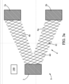
- Such a method comprises the provision 100 of a single-piece assembly 9 for defining the geometry of the mechanical support structure, an example of which is schematically shown in FIG. Figure 3a .
- This single-piece assembly comprises the first interface portion(s) 2 with the equipment 10, the second interface portion(s) 3 with the space platform 20, and the metal mesh 4 connecting said portions together.
- an interface portion may be a part of a partition of the space instrument or a partition of the spacecraft carrying the instrument, said partition then being extended by the corresponding interface portion.
- a first interface portion 2 with the instrument may be a part of a partition delimiting a cavity containing a material heat transfer medium providing thermal regulation of the instrument, such as a heat transfer structure with two-phase material, for example a heat pipe.
- the single-piece assembly 9 further comprises a mesh 4, also made of metal, which can be made of the same metal or metal alloy as the interface portions 2, 3, and forming a mechanical connection between the first interface portion 2 and the second interface portion 3.
- the mesh 4 is advantageously made in one piece with the interface portions 2, 3, being devoid of a hinge.
- the single-piece assembly 9 is made in one piece with a partition of the space instrument.
- the assembly comprising the interface portions 2, 3, and the metal mesh 4 forms a assembly 9 for defining the geometry of the mechanical support structure 1, because the geometry of the mesh, in particular its width and its depth between two interface portions, and the geometry and the relative positions of the interface portions, define the geometry of the structure obtained at the end of the process.
- This single-piece assembly 9 is advantageously made of a single metal part. It can be manufactured by additive manufacturing, for example during a preliminary step 90 of the process.
- the method then comprises the manufacture of the block 5 of mechanically rigid and thermally insulating material filling the interstices of the mesh 4.
- this step can be carried out by casting the constituent material of the molten block into the mesh, for example glass.
- the method then comprises a step 200 of casting the molten material into the metal mesh and against the first 2 and second 3 interface portions.
- the material in this case is chosen to have, in the molten state, a viscosity that is low enough to allow it to fill the interstices of the mesh and to form a mechanically rigid block once cooled.
- the size of the interstices of the mesh is also determined as a function of the material that is then cast in the molten state into the interstices of the mesh so as to fill these interstices, and of the technique used to carry out the casting.
- the cast material takes the form of a block 5 of mechanically rigid and thermally insulating material, resting against the interface portions and filling the mesh, that is to say at least partially filling the interstices of the mesh.
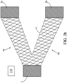
- Casting 200 may include, with reference to the figure 3b , a preliminary step 210 of positioning the single-piece assembly in a mold 6, the walls of which delimit the outline of the mechanical support structure to be produced, and more precisely the outlines of the block of material 5.
- the walls of the mold bear against the interface portions 2, 3 and extend around the outer outline of the mesh 4.
- the shape of the block of material 5 delimited by the mold corresponds to that of the mesh.
- the block of material also has a V shape with two rectilinear portions 5a, 5b connecting the interface portion 2 with each portion 3a, 3b respectively.
- the walls of the mold can however be spaced from the external contour of the mesh, for example by a distance less than or equal to the length of the edges of the mesh, which corresponds once the material has hardened to a circumferential portion around the mesh and devoid of rods of the mesh.
- the single-piece assembly 9, and where appropriate the mold in which it is placed for the purpose of casting the glass, are furthermore heated 220 in an oven, to a temperature lower than that of the melting of the glass, but preferably greater than or equal to the glass transition temperature of the glass, for example between 500 and 600°C, for example at 550°C.
- This heating step makes it possible to reduce the thermal shock between the glass and the single-piece assembly during casting and thus allow the glass to penetrate and fill all of the interstices of the mesh.
- the glass after synthesis and cooling, is preferably refined before being cast, that is to say it is heated 230 to be freed from the air bubbles that it may contain, and also to make it liquid in order to be cast.
- This step of refining and melting the glass can be carried out for example in another furnace at a temperature higher than 800°C, for example 1000°C or more.
- the actual pouring of the molten glass into the monobloc assembly can be carried out by gravity or by injection 240, after having removed the glass on the one hand, and the monobloc assembly on the other hand from their respective furnaces.
- This step is shown schematically in figure 3c .
- the structure comprising the monobloc assembly positioned in the mold and the glass filling the interstices of the mesh of the monobloc assembly are then replaced in an oven at the temperature of glass transition of the glass for mechanical annealing 250, allowing the stresses to be released.
- the duration of this annealing can be at least two hours.
- the process includes cooling the cast material 300 to obtain the rigid block.
- the structure is removed from the oven to gradually cool to room temperature.
- the mold can be before or after the temperature of the structure has reached room temperature.
- the structure obtained after removal of the mold is schematically shown in the 3d figure .
- the mechanical support structure 1 is obtained, exhibiting significant stiffness and enabling thermal insulation of the space equipment relative to the platform, due to the small relative surface area of the rods constituting the mesh relative to the block of thermally insulating material.
Landscapes
- Engineering & Computer Science (AREA)
- Aviation & Aerospace Engineering (AREA)
- Remote Sensing (AREA)
- General Health & Medical Sciences (AREA)
- Health & Medical Sciences (AREA)
- Emergency Medicine (AREA)
- Physics & Mathematics (AREA)
- Critical Care (AREA)
- Thermal Sciences (AREA)
- Life Sciences & Earth Sciences (AREA)
- Biodiversity & Conservation Biology (AREA)
- Environmental & Geological Engineering (AREA)
- Environmental Sciences (AREA)
- Toxicology (AREA)
- Thermal Insulation (AREA)
- Patch Boards (AREA)
- Casings For Electric Apparatus (AREA)
Claims (7)
- Anordnung aufweisend eine thermisch regulierte Raumausrüstung (10) und mindestens eine mechanische Stützstruktur (1) zum Stützen der Raumausrüstung (10), wobei die Struktur (1) einen ersten metallischen Schnittstellenabschnitt mit der Ausrüstung (10) aufweist, der mit mindestens einem zweiten metallischen Schnittstellenabschnitt (3) mit einer Raumplattform (20) verbunden ist, wobei die mechanische Stützstruktur ferner mindestens ein Metallnetz (4) aufweist, das eine mechanische Verbindung zwischen dem ersten und zweiten Schnittstellenabschnitt (2, 3) bildet,
dadurch gekennzeichnet, dass die mechanische Stützstruktur (1) außerdem mindestens einen mechanisch steifen und thermisch isolierenden Materialblock aufweist, der den ersten und zweiten Schnittstellenabschnitt (2, 3) kontinuierlich und starr verbindet und das Metallnetz füllt. - Anordnung nach Anspruch 1, in welcher das Netz (4) eine dreidimensionale Zusammenstellung mehrerer Stäbe (40) aufweist, die untereinander verbunden sind, um zwischen sich Zwischenräume (41) zu bilden.
- Anordnung nach Anspruch 1 oder 2, in welcher die aus dem ersten Schnittstellenabschnitt (2), dem zweiten Schnittstellenabschnitt (3) und dem Metallnetz (4) gebildete Anordnung aus einem einzigen Block besteht, wobei mindestens eine Wand der Raumausrüstung (10) von dem ersten Schnittstellenabschnitt (2) verlängert wird.
- Anordnung nach einem der vorstehenden Ansprüche, wobei das Netz (4) und der erste (2) und zweite (3) Schnittstellenabschnitt aus einer Legierung von Titan, Aluminium und Vanadium oder aus einer Legierung von Eisen und Nickel, beispielsweise zusammengesetzt aus 64% Eisen und 36% Nickel, hergestellt sind.
- Anordnung nach einem der vorstehenden Ansprüche, in welcher der mechanisch steife und thermisch isolierende Materialblock (4) aus einer Keramik oder Glas besteht.
- Anordnung nach einem der vorstehenden Ansprüche, in welcher die mechanische Stützstruktur (1) einen V-förmigen Fuß definiert, bei dem die Spitze des V durch den ersten Schnittstellenabschnitt (2a) verlängert ist, der durch zwei V-förmige Metallnetze (5a, 5b) bis zu zwei zweiten Schnittstellenabschnitten (3a, 3b) verlängert ist, wobei die V-förmigen Netze, die mindestens teilweise in dem mechanisch steifen und thermisch isolierenden Materialblock eingebettet sind, zwei mechanische Verbindungen zwischen dem ersten und zweiten Schnittstellenabschnitt bilden.
- Anordnung nach einem der vorstehenden Ansprüche, wobei die Ausrüstung aus einem Beobachtungsinstrument und einem Kryostaten ausgewählt ist.
Applications Claiming Priority (2)
| Application Number | Priority Date | Filing Date | Title |
|---|---|---|---|
| FR2204638A FR3135451A1 (fr) | 2022-05-16 | 2022-05-16 | Equipement spatial thermorégulé à soutien mécanique thermiquement isolant |
| PCT/FR2023/050680 WO2023222966A1 (fr) | 2022-05-16 | 2023-05-12 | Equipement spatial thermorégulé à soutien mécanique thermiquement isolant |
Publications (2)
| Publication Number | Publication Date |
|---|---|
| EP4392330A1 EP4392330A1 (de) | 2024-07-03 |
| EP4392330B1 true EP4392330B1 (de) | 2024-12-18 |
Family
ID=82942758
Family Applications (1)
| Application Number | Title | Priority Date | Filing Date |
|---|---|---|---|
| EP23729803.9A Active EP4392330B1 (de) | 2022-05-16 | 2023-05-12 | Thermisch regulierte raumausrüstung mit thermisch isolierender mechanischer stütze |
Country Status (3)
| Country | Link |
|---|---|
| EP (1) | EP4392330B1 (de) |
| FR (1) | FR3135451A1 (de) |
| WO (1) | WO2023222966A1 (de) |
Family Cites Families (8)
| Publication number | Priority date | Publication date | Assignee | Title |
|---|---|---|---|---|
| CN103241391B (zh) * | 2013-04-25 | 2016-03-16 | 上海卫星工程研究所 | 用于火星着陆器热控制的隔热组件及其制备方法 |
| FR3040777B1 (fr) | 2015-09-04 | 2019-04-19 | Thales | Ensemble de detection optique comportant un detecteur optique a controle thermique ameliore, instrument d'observation et satellite comportant un tel ensemble de detection optique |
| CN105667837A (zh) * | 2015-09-15 | 2016-06-15 | 大连理工大学 | 一种含流道的金字塔微桁架夹芯板式承载与热防护一体化结构 |
| US10913232B2 (en) * | 2016-08-30 | 2021-02-09 | Quest Thermal Group LLC | Cellular load-responsive multilayer insulation |
| CN110356591B (zh) * | 2019-08-15 | 2021-07-16 | 中国科学院长春光学精密机械与物理研究所 | 一种隔热垫 |
| CN111891389A (zh) * | 2020-08-05 | 2020-11-06 | 上海卫星工程研究所 | 一种3d打印钛合金隔热垫 |
| CN113562202B (zh) * | 2021-08-24 | 2022-07-29 | 北京理工大学 | 基于相变材料的多层防隔热承载一体化点阵热防护系统 |
| CN114084382A (zh) * | 2021-11-25 | 2022-02-25 | 北京微纳星空科技有限公司 | 一种柔性支架及空间遥感相机 |
-
2022
- 2022-05-16 FR FR2204638A patent/FR3135451A1/fr not_active Ceased
-
2023
- 2023-05-12 EP EP23729803.9A patent/EP4392330B1/de active Active
- 2023-05-12 WO PCT/FR2023/050680 patent/WO2023222966A1/fr not_active Ceased
Also Published As
| Publication number | Publication date |
|---|---|
| WO2023222966A1 (fr) | 2023-11-23 |
| FR3135451A1 (fr) | 2023-11-17 |
| EP4392330A1 (de) | 2024-07-03 |
Similar Documents
| Publication | Publication Date | Title |
|---|---|---|
| EP2714303B1 (de) | Verfahren zur herstellung eines metallschaums mit kanälen und resultierender metallschaum | |
| CA2509486C (fr) | Procede de fabrication d'un carter de stator de turbine | |
| EP3208200B1 (de) | Monoblockstruktur für satellitenpaneel | |
| EP2983849B9 (de) | Monokristalline schmelzform | |
| FR3041889A1 (fr) | Procede de fabrication additive comprenant une etape de pressage isostatique a chaud | |
| WO2023222966A1 (fr) | Equipement spatial thermorégulé à soutien mécanique thermiquement isolant | |
| EP0486396A1 (de) | Verfahren zum Löten eines sich quer zu einer Wand befindenden Elementes, Verbindungseinheit zur Durchführung eines solchen Lötverfahrens, Gehäuse eines elektronischen Schaltkreises | |
| CA3123337C (fr) | Procede de fixation d'un equipement dissipatif, mur de vehicule spatial et vehicule spatial | |
| FR2955274A1 (fr) | Procede de moulage en moule perdu et installation pour la mise en œuvre de ce procede | |
| EP3833854B1 (de) | Innengehäuse einer turbomaschine mit verbesserter wärmeisolierung | |
| EP3475012B1 (de) | Kühlofen mit gerichteter erstarrung und kühlverfahren mit solch einem ofen | |
| WO2013014369A1 (fr) | Procede d'assemblage d'une coque titane et d'une coque alliage resistant au feu titane | |
| EP0290323B1 (de) | Gradientofen zum gerichteten Erstarren, insbesondere durch das Bridgmann-Verfahren | |
| FR3139741A1 (fr) | Grappe de modeles realises en cire et moule pour la fabrication par moulage a cire perdue d’une pluralite d’elements de turbomachine | |
| EP2487020B1 (de) | Verfahren zum Verbinden von Dichtungsfugen | |
| FR3148288A1 (fr) | Four et procede de chauffage ou de prechauffage pour une analyse par tomographie | |
| WO2024110735A1 (fr) | Procédé de formation d'une pièce par insertion d'un alliage métallique à l'état solide dans une grappe | |
| FR3079021A1 (fr) | Dispositif de conduction thermique et systeme de dissipation de chaleur associe | |
| FR3145974A1 (fr) | Procédé de fabrication d’échangeur de chaleur par projection dynamique à froid et échangeur de chaleur associé | |
| FR3116313A1 (fr) | Ressort élastique à spires, système d’amortissement et procédé de fabrication associés | |
| FR3065660B1 (fr) | Ensemble pour la fabrication d'une aube de turbomachine | |
| FR3141247A1 (fr) | Procede de fabrication de plusieurs eprouvettes bi-materiaux | |
| FR3108539A1 (fr) | Procede de solidification dirigee pour alliages metalliques et modele en materiau eliminable pour le procede | |
| WO2019122111A1 (fr) | Creuset pour solidification dirigee | |
| EP4399152A1 (de) | Kryostat für ein raumbauteil |
Legal Events
| Date | Code | Title | Description |
|---|---|---|---|
| STAA | Information on the status of an ep patent application or granted ep patent |
Free format text: STATUS: UNKNOWN |
|
| STAA | Information on the status of an ep patent application or granted ep patent |
Free format text: STATUS: THE INTERNATIONAL PUBLICATION HAS BEEN MADE |
|
| PUAI | Public reference made under article 153(3) epc to a published international application that has entered the european phase |
Free format text: ORIGINAL CODE: 0009012 |
|
| STAA | Information on the status of an ep patent application or granted ep patent |
Free format text: STATUS: REQUEST FOR EXAMINATION WAS MADE |
|
| 17P | Request for examination filed |
Effective date: 20240325 |
|
| AK | Designated contracting states |
Kind code of ref document: A1 Designated state(s): AL AT BE BG CH CY CZ DE DK EE ES FI FR GB GR HR HU IE IS IT LI LT LU LV MC ME MK MT NL NO PL PT RO RS SE SI SK SM TR |
|
| GRAP | Despatch of communication of intention to grant a patent |
Free format text: ORIGINAL CODE: EPIDOSNIGR1 |
|
| STAA | Information on the status of an ep patent application or granted ep patent |
Free format text: STATUS: GRANT OF PATENT IS INTENDED |
|
| DAV | Request for validation of the european patent (deleted) | ||
| DAX | Request for extension of the european patent (deleted) | ||
| INTG | Intention to grant announced |
Effective date: 20240726 |
|
| GRAS | Grant fee paid |
Free format text: ORIGINAL CODE: EPIDOSNIGR3 |
|
| GRAA | (expected) grant |
Free format text: ORIGINAL CODE: 0009210 |
|
| STAA | Information on the status of an ep patent application or granted ep patent |
Free format text: STATUS: THE PATENT HAS BEEN GRANTED |
|
| AK | Designated contracting states |
Kind code of ref document: B1 Designated state(s): AL AT BE BG CH CY CZ DE DK EE ES FI FR GB GR HR HU IE IS IT LI LT LU LV MC ME MK MT NL NO PL PT RO RS SE SI SK SM TR |
|
| REG | Reference to a national code |
Ref country code: CH Ref legal event code: EP |
|
| REG | Reference to a national code |
Ref country code: DE Ref legal event code: R096 Ref document number: 602023001419 Country of ref document: DE |
|
| REG | Reference to a national code |
Ref country code: IE Ref legal event code: FG4D Free format text: LANGUAGE OF EP DOCUMENT: FRENCH |
|
| REG | Reference to a national code |
Ref country code: LT Ref legal event code: MG9D |
|
| PG25 | Lapsed in a contracting state [announced via postgrant information from national office to epo] |
Ref country code: HR Free format text: LAPSE BECAUSE OF FAILURE TO SUBMIT A TRANSLATION OF THE DESCRIPTION OR TO PAY THE FEE WITHIN THE PRESCRIBED TIME-LIMIT Effective date: 20241218 |
|
| PG25 | Lapsed in a contracting state [announced via postgrant information from national office to epo] |
Ref country code: FI Free format text: LAPSE BECAUSE OF FAILURE TO SUBMIT A TRANSLATION OF THE DESCRIPTION OR TO PAY THE FEE WITHIN THE PRESCRIBED TIME-LIMIT Effective date: 20241218 |
|
| PG25 | Lapsed in a contracting state [announced via postgrant information from national office to epo] |
Ref country code: BG Free format text: LAPSE BECAUSE OF FAILURE TO SUBMIT A TRANSLATION OF THE DESCRIPTION OR TO PAY THE FEE WITHIN THE PRESCRIBED TIME-LIMIT Effective date: 20241218 |
|
| PG25 | Lapsed in a contracting state [announced via postgrant information from national office to epo] |
Ref country code: NO Free format text: LAPSE BECAUSE OF FAILURE TO SUBMIT A TRANSLATION OF THE DESCRIPTION OR TO PAY THE FEE WITHIN THE PRESCRIBED TIME-LIMIT Effective date: 20250318 |
|
| REG | Reference to a national code |
Ref country code: NL Ref legal event code: MP Effective date: 20241218 |
|
| PG25 | Lapsed in a contracting state [announced via postgrant information from national office to epo] |
Ref country code: LV Free format text: LAPSE BECAUSE OF FAILURE TO SUBMIT A TRANSLATION OF THE DESCRIPTION OR TO PAY THE FEE WITHIN THE PRESCRIBED TIME-LIMIT Effective date: 20241218 Ref country code: GR Free format text: LAPSE BECAUSE OF FAILURE TO SUBMIT A TRANSLATION OF THE DESCRIPTION OR TO PAY THE FEE WITHIN THE PRESCRIBED TIME-LIMIT Effective date: 20250319 |
|
| PG25 | Lapsed in a contracting state [announced via postgrant information from national office to epo] |
Ref country code: RS Free format text: LAPSE BECAUSE OF FAILURE TO SUBMIT A TRANSLATION OF THE DESCRIPTION OR TO PAY THE FEE WITHIN THE PRESCRIBED TIME-LIMIT Effective date: 20250318 |
|
| PG25 | Lapsed in a contracting state [announced via postgrant information from national office to epo] |
Ref country code: NL Free format text: LAPSE BECAUSE OF FAILURE TO SUBMIT A TRANSLATION OF THE DESCRIPTION OR TO PAY THE FEE WITHIN THE PRESCRIBED TIME-LIMIT Effective date: 20241218 |
|
| REG | Reference to a national code |
Ref country code: AT Ref legal event code: MK05 Ref document number: 1752084 Country of ref document: AT Kind code of ref document: T Effective date: 20241218 |
|
| PG25 | Lapsed in a contracting state [announced via postgrant information from national office to epo] |
Ref country code: SM Free format text: LAPSE BECAUSE OF FAILURE TO SUBMIT A TRANSLATION OF THE DESCRIPTION OR TO PAY THE FEE WITHIN THE PRESCRIBED TIME-LIMIT Effective date: 20241218 |
|
| PG25 | Lapsed in a contracting state [announced via postgrant information from national office to epo] |
Ref country code: PL Free format text: LAPSE BECAUSE OF FAILURE TO SUBMIT A TRANSLATION OF THE DESCRIPTION OR TO PAY THE FEE WITHIN THE PRESCRIBED TIME-LIMIT Effective date: 20241218 |
|
| PG25 | Lapsed in a contracting state [announced via postgrant information from national office to epo] |
Ref country code: ES Free format text: LAPSE BECAUSE OF FAILURE TO SUBMIT A TRANSLATION OF THE DESCRIPTION OR TO PAY THE FEE WITHIN THE PRESCRIBED TIME-LIMIT Effective date: 20241218 |
|
| PG25 | Lapsed in a contracting state [announced via postgrant information from national office to epo] |
Ref country code: IS Free format text: LAPSE BECAUSE OF FAILURE TO SUBMIT A TRANSLATION OF THE DESCRIPTION OR TO PAY THE FEE WITHIN THE PRESCRIBED TIME-LIMIT Effective date: 20250418 |
|
| PG25 | Lapsed in a contracting state [announced via postgrant information from national office to epo] |
Ref country code: PT Free format text: LAPSE BECAUSE OF FAILURE TO SUBMIT A TRANSLATION OF THE DESCRIPTION OR TO PAY THE FEE WITHIN THE PRESCRIBED TIME-LIMIT Effective date: 20250421 |
|
| PG25 | Lapsed in a contracting state [announced via postgrant information from national office to epo] |
Ref country code: EE Free format text: LAPSE BECAUSE OF FAILURE TO SUBMIT A TRANSLATION OF THE DESCRIPTION OR TO PAY THE FEE WITHIN THE PRESCRIBED TIME-LIMIT Effective date: 20241218 |
|
| PGFP | Annual fee paid to national office [announced via postgrant information from national office to epo] |
Ref country code: FR Payment date: 20250422 Year of fee payment: 3 |
|
| PG25 | Lapsed in a contracting state [announced via postgrant information from national office to epo] |
Ref country code: AT Free format text: LAPSE BECAUSE OF FAILURE TO SUBMIT A TRANSLATION OF THE DESCRIPTION OR TO PAY THE FEE WITHIN THE PRESCRIBED TIME-LIMIT Effective date: 20241218 Ref country code: RO Free format text: LAPSE BECAUSE OF FAILURE TO SUBMIT A TRANSLATION OF THE DESCRIPTION OR TO PAY THE FEE WITHIN THE PRESCRIBED TIME-LIMIT Effective date: 20241218 |
|
| PG25 | Lapsed in a contracting state [announced via postgrant information from national office to epo] |
Ref country code: SK Free format text: LAPSE BECAUSE OF FAILURE TO SUBMIT A TRANSLATION OF THE DESCRIPTION OR TO PAY THE FEE WITHIN THE PRESCRIBED TIME-LIMIT Effective date: 20241218 |
|
| PG25 | Lapsed in a contracting state [announced via postgrant information from national office to epo] |
Ref country code: CZ Free format text: LAPSE BECAUSE OF FAILURE TO SUBMIT A TRANSLATION OF THE DESCRIPTION OR TO PAY THE FEE WITHIN THE PRESCRIBED TIME-LIMIT Effective date: 20241218 |
|
| PG25 | Lapsed in a contracting state [announced via postgrant information from national office to epo] |
Ref country code: IT Free format text: LAPSE BECAUSE OF FAILURE TO SUBMIT A TRANSLATION OF THE DESCRIPTION OR TO PAY THE FEE WITHIN THE PRESCRIBED TIME-LIMIT Effective date: 20241218 |
|
| PG25 | Lapsed in a contracting state [announced via postgrant information from national office to epo] |
Ref country code: SE Free format text: LAPSE BECAUSE OF FAILURE TO SUBMIT A TRANSLATION OF THE DESCRIPTION OR TO PAY THE FEE WITHIN THE PRESCRIBED TIME-LIMIT Effective date: 20241218 |
|
| REG | Reference to a national code |
Ref country code: DE Ref legal event code: R097 Ref document number: 602023001419 Country of ref document: DE |
|
| PG25 | Lapsed in a contracting state [announced via postgrant information from national office to epo] |
Ref country code: DK Free format text: LAPSE BECAUSE OF FAILURE TO SUBMIT A TRANSLATION OF THE DESCRIPTION OR TO PAY THE FEE WITHIN THE PRESCRIBED TIME-LIMIT Effective date: 20241218 |
|
| PLBE | No opposition filed within time limit |
Free format text: ORIGINAL CODE: 0009261 |
|
| STAA | Information on the status of an ep patent application or granted ep patent |
Free format text: STATUS: NO OPPOSITION FILED WITHIN TIME LIMIT |
|
| 26N | No opposition filed |
Effective date: 20250919 |
|
| REG | Reference to a national code |
Ref country code: DE Ref legal event code: R119 Ref document number: 602023001419 Country of ref document: DE |
|
| PG25 | Lapsed in a contracting state [announced via postgrant information from national office to epo] |
Ref country code: LU Free format text: LAPSE BECAUSE OF NON-PAYMENT OF DUE FEES Effective date: 20250512 |
|
| REG | Reference to a national code |
Ref country code: BE Ref legal event code: MM Effective date: 20250531 |
|
| PG25 | Lapsed in a contracting state [announced via postgrant information from national office to epo] |
Ref country code: MC Free format text: LAPSE BECAUSE OF FAILURE TO SUBMIT A TRANSLATION OF THE DESCRIPTION OR TO PAY THE FEE WITHIN THE PRESCRIBED TIME-LIMIT Effective date: 20241218 |
|
| PG25 | Lapsed in a contracting state [announced via postgrant information from national office to epo] |
Ref country code: DE Free format text: LAPSE BECAUSE OF NON-PAYMENT OF DUE FEES Effective date: 20251202 Ref country code: IE Free format text: LAPSE BECAUSE OF NON-PAYMENT OF DUE FEES Effective date: 20250512 |
|
| PG25 | Lapsed in a contracting state [announced via postgrant information from national office to epo] |
Ref country code: BE Free format text: LAPSE BECAUSE OF NON-PAYMENT OF DUE FEES Effective date: 20250531 |