EP3940352B1 - Weighing scale diagnostics method - Google Patents
Weighing scale diagnostics method Download PDFInfo
- Publication number
- EP3940352B1 EP3940352B1 EP21193693.5A EP21193693A EP3940352B1 EP 3940352 B1 EP3940352 B1 EP 3940352B1 EP 21193693 A EP21193693 A EP 21193693A EP 3940352 B1 EP3940352 B1 EP 3940352B1
- Authority
- EP
- European Patent Office
- Prior art keywords
- scale
- weighing scale
- force measuring
- load cell
- diagnostic
- Prior art date
- Legal status (The legal status is an assumption and is not a legal conclusion. Google has not performed a legal analysis and makes no representation as to the accuracy of the status listed.)
- Active
Links
- 238000005303 weighing Methods 0.000 title claims description 103
- 238000000034 method Methods 0.000 title description 21
- 238000002405 diagnostic procedure Methods 0.000 claims description 43
- 230000008859 change Effects 0.000 description 15
- 238000009825 accumulation Methods 0.000 description 9
- 238000013461 design Methods 0.000 description 9
- 238000000528 statistical test Methods 0.000 description 9
- 238000012360 testing method Methods 0.000 description 7
- 230000006870 function Effects 0.000 description 6
- 238000004891 communication Methods 0.000 description 5
- 230000008569 process Effects 0.000 description 5
- 230000007613 environmental effect Effects 0.000 description 4
- 238000007619 statistical method Methods 0.000 description 4
- 238000012544 monitoring process Methods 0.000 description 3
- 229910000831 Steel Inorganic materials 0.000 description 2
- 238000012631 diagnostic technique Methods 0.000 description 2
- 238000011156 evaluation Methods 0.000 description 2
- 230000036541 health Effects 0.000 description 2
- 239000010959 steel Substances 0.000 description 2
- 230000001960 triggered effect Effects 0.000 description 2
- 206010000117 Abnormal behaviour Diseases 0.000 description 1
- 238000001047 Dixon's Q test Methods 0.000 description 1
- 238000003658 Grubbs' test for outlier Methods 0.000 description 1
- 230000005856 abnormality Effects 0.000 description 1
- 230000009471 action Effects 0.000 description 1
- 238000010276 construction Methods 0.000 description 1
- 238000012937 correction Methods 0.000 description 1
- 230000001186 cumulative effect Effects 0.000 description 1
- 239000000428 dust Substances 0.000 description 1
- 238000012423 maintenance Methods 0.000 description 1
- 238000005259 measurement Methods 0.000 description 1
- 239000002184 metal Substances 0.000 description 1
- 238000012986 modification Methods 0.000 description 1
- 230000004048 modification Effects 0.000 description 1
- 238000011084 recovery Methods 0.000 description 1
- 230000004044 response Effects 0.000 description 1
- 238000012552 review Methods 0.000 description 1
- 230000035945 sensitivity Effects 0.000 description 1
- 238000012549 training Methods 0.000 description 1
Images

Classifications
-
- G—PHYSICS
- G01—MEASURING; TESTING
- G01G—WEIGHING
- G01G23/00—Auxiliary devices for weighing apparatus
- G01G23/01—Testing or calibrating of weighing apparatus
-
- G—PHYSICS
- G01—MEASURING; TESTING
- G01G—WEIGHING
- G01G23/00—Auxiliary devices for weighing apparatus
- G01G23/18—Indicating devices, e.g. for remote indication; Recording devices; Scales, e.g. graduated
- G01G23/36—Indicating the weight by electrical means, e.g. using photoelectric cells
- G01G23/37—Indicating the weight by electrical means, e.g. using photoelectric cells involving digital counting
- G01G23/3728—Indicating the weight by electrical means, e.g. using photoelectric cells involving digital counting with wireless means
- G01G23/3735—Indicating the weight by electrical means, e.g. using photoelectric cells involving digital counting with wireless means using a digital network
Definitions
- Embodiments of the invention generally relate to weighing scale diagnostic methods employing a comparison of like component operating parameters.
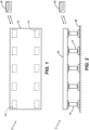
- Weighing scales exist in many forms, from small laboratory scales to large vehicle weighing scales. Of particular interest herein are weighing scales having multiple force measuring devices, which force measuring devices may be modular in nature.
- a scale having multiple force measuring devices will also typically include a frame, a load receiving surface that interfaces with the force measuring devices, and a controller and/or monitor that receives signals from the force measuring devices and typically provides a readout of the weight of an object residing on the scale.
- a vehicle weighing scale is a common example of a multiple force measuring device weighing scale.
- a typical vehicle weighing scale includes at least one scale platform (or deck) for receiving a vehicle to be weighed.
- Such a scale platform is often comprised of a metal framework with a steel plate deck, or the scale platform may be comprised of concrete (typically enclosed within a steel frame).
- the scale platform is normally supported from beneath by a number of force measuring devices, such as load cells.
- Vehicle weighing scales are also typically constructed with two rows of load cells aligned in the direction of vehicle travel across the scale platform. When a vehicle is placed on the scale platform, each load cell produces an output signal that reflects the portion of the vehicle weight borne by that load cell. The signals from the load cells are added to produce an indication of the total weight of the vehicle residing on the scale platform of the weighing scale.
- Vehicle weighing scales can be of various size.
- vehicle weighing scales are commonly of a size that is sufficient to accommodate a multi-axle vehicle, such as a semi-truck trailer.
- Vehicle scales of such size may be assembled using multiple scale platform segments (modules) that are connected end-to-end to provide a full- length scale platform.
- a monitoring methodology must be developed and particular scale behavior, or the behavior (e.g., operating characteristics) of one or more scale components must be evaluated.
- JP 3199129 B2 An apparatus for diagnosing faults in load cells of a weighing hopper and a failure self-recovery device are disclosed in JP 3199129 B2 .
- the outputs of the non-faulty sensors are multiplied by a predetermined coefficient and the overall weight value is predicted.
- Another hopper-type measuring apparatus comprising three load cells is disclosed in JP 2012193996 A , which describes a comparator and a span abnormality detector, which together detect the load cell that displays abnormal behavior.
- An electronic belt scale comprising four weighing sensors is disclosed in US 20120059626 A1 .
- the four weighing sensors are respectively connected with the accumulator, which obtains a group of main accumulation values and two groups of auxiliary accumulation values based on the outputs of the four weighing sensors.
- the two groups of auxiliary accumulation values are compared with each other. If the difference between the two groups of auxiliary accumulation values is within the setting range, the main accumulation value is displayed. If the difference between the two groups of auxiliary accumulation values is beyond the setting range, the weighing sensor(s) is declared to be faulty and the normal auxiliary accumulation value is displayed.
- It is known to evaluate weighing scale function by monitoring the operational characteristics of the scale's force measuring devices. More particularly, one or more selected force measuring device operational characteristics may be monitored and compared to a corresponding expected operational characteristic. Associated threshold values may then be set around the expected operational characteristic, with a reading below or above said threshold values being indicative of improper operation or some other problem.
- a negative issue associated with such a known evaluation methodology is that of setting individual component operating characteristic threshold values.
- the threshold values are generally set to trigger an alarm or to provide some other notice or indication if monitored force measuring device operational characteristics exceed the preset threshold values.
- Exemplary weighing scale diagnostic method embodiments described herein generally include monitoring and comparing one or more operating parameters of like scale components, which are, for purposes of the invention, scale components that under normal conditions will have at least one common monitorable parameter that has approximately the same value for each component.
- Exemplary weighing scale diagnostic method embodiments described herein are, therefore, adapted particularly for use with weighing scales having multiple like components.
- Like weighing scale components may include, but are not limited to, a plurality of the same or similar force measuring devices, which may be in the form of force measuring modules.
- An operating parameter of such a like component may be any component parameter having a monitorable output that may be used as an indicator of component or scale health.
- such operating parameters may include, but are not necessarily limited to, zero balance change (i.e., weight output change over time with only the dead load applied), temperature, digital signal voltage and supply voltage.
- exemplary method embodiments according to the invention may be practiced by comparing the same parameter of a plurality of like components present in a given weighing scale. For example, various operating parameters of the force measuring devices present in a multiple force measuring device weighing scale may be compared and evaluated.
- One exemplary weighing scale diagnostic method includes selecting a plurality of like weighing scale components to be monitored; selecting an operating parameter common to the selected weighing scale components as a diagnostic parameter; receiving at a computer device output signals representative of the selected diagnostic parameter from each of the selected scale components; comparing the output signal value received from each selected weighing scale component to the output signal values received from all of the other selected weighing scale components; calculating the maximum difference between the output signal values of any two selected weighing scale components; comparing the maximum difference between the output signal values of any two selected weighing scale components with a maximum allowed difference; and, if the calculated difference is determined to exceed the maximum allowed difference, indicating a weighing scale component problem.
- Yet another exemplary weighing scale diagnostic method includes selecting a plurality of like weighing scale components to be monitored; selecting an operating parameter common to the selected weighing scale components as a diagnostic parameter; receiving at a computer device output signals representative of the selected diagnostic parameter from each of the selected scale components; applying a standard statistical test for outliers i.e. Chauvenet's Criterion; and, if the diagnostic parameter value associated with a given weighing scale component is statistically determined to be an outlier, indicating a problem with that weighing scale component.
- a standard statistical test for outliers i.e. Chauvenet's Criterion
- the weighing scale may be a vehicle scale.
- the weighing scale components to be monitored are the force measuring devices (e.g., modules) of the weighing scale, and the force measuring devices may be load cells.
- the selected diagnostic parameter may be for example the load cell temperature, digital signal voltage, supply voltage, or zero balance change.
- While some small difference in individual force measuring device temperature readings may be expected due to the physical distance between the force measuring devices, a temperature difference between any two like force measuring devices that exceeds some difference limit, a temperature of a given force measuring device that deviates more than some maximum allowed amount from a calculated measure of central tendency of the temperature value of the other like force measuring devices, or a temperature of a given force measuring device that is determined by statistical analysis to be an outlier from the temperature of other like force measuring devices may indicate a problem (e.g., a failing temperature sensor) and can be used to trigger an alert, such as an alarm.
- a problem e.g., a failing temperature sensor
- the selected diagnostic parameter is the supply voltage of the individual force measuring devices of a multiple force measuring device weighing scale.
- an operating supply voltage is provided by a controller (e.g., a terminal) to all of the like force measuring devices of the scale. The supply voltage at each force measuring device is monitored. The supply voltage should be approximately the same for all of the force measuring devices in the system.
- a weighing scale evaluated using a method wherein the percentage of total deviation that is attributable to each selected scale component is compared to a second predetermined threshold value may be also be a vehicle scale, the weighing scale components to be monitored may again be the force measuring devices of the weighing scale, and the force measuring devices may be load cells (e.g., load cell modules).
- the selected diagnostic parameter may be the zero drift of the force measuring devices (e.g., load cells)
- the calculated deviation of the output signal value received from each force measuring device may be the zero drift of each force measuring device
- the calculated total deviation may be the total zero drift of the scale.
- the first predetermined threshold value may be some percentage of scale capacity and the second predetermined threshold value may be some percentage of total zero drift.
- the selected diagnostic parameter is the zero balance change of the individual force measuring devices (e.g., load cell modules) of a multiple force measuring device weighing scale.
- the zero balance change is the difference between the zero balance value at the current time compared with its value at the time of calibration.
- the zero balance change of all the individual force measuring devices is monitored.
- the zero balance change should be approximately the same for all of the force measuring devices of the scale.
- a zero balance change of a given force measuring device that represents a significant percentage of the total zero balance change of all the force measuring devices may indicate a problem (e.g., a failing force measuring device) and can be used to trigger an alert, such as an alarm.
- weighing scales exist in many forms, sizes and capacities. While method embodiments of the invention are not limited in application to weighing scales of any particular form, size or capacity, said methods are adapted for use with weighing scales having a plurality of like components.
- the like components may be force measuring devices.
- the force measuring devices may be load cells or other devices usable to provide weight indicative readings in one form or another.
- At least the load cells 15 of the scale 5 are also in wired or wireless communication (as indicated by the bi-directional arrows) with a computer device 25 that is operative to control the scale, to display weight readings when the scale is loaded, and possibly to display diagnostic information related to the scale and its components.
- the computer device is a scale terminal, which includes a processor, memory, and appropriate programming.
- scale functionality may be evaluated in one embodiment by selecting as a diagnostic parameter(s) one or more operating parameters that are common to each of the load cells 15.
- the selected diagnostic parameter(s) have approximately the same value for each load cell during normal operation.
- This diagnostic parameter(s) is then monitored for each load cell 15 and the detected value associated with the diagnostic parameter(s) of each load cell 15 is compared with the detected values associated with the same diagnostic parameters of the other load cells 15.
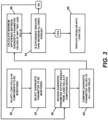
- the load cells 15 of the scale 5 are selected as the component to be monitored 30 and a diagnostic parameter (e.g., temperature, digital signal voltage, supply voltage, or zero balance change) of the individual load cells 15 of the vehicle weighing scale 5 is selected to be monitored 35.
- a diagnostic parameter e.g., temperature, digital signal voltage, supply voltage, or zero balance change
- Appropriate diagnostic parameter signals from the load cells 15 are received 40 by the computer device (e.g., terminal) 25.
- the diagnostic parameter value of each load cell 15 is compared to the diagnostic parameter values of the other load cells 45, and a calculated difference between the diagnostic parameter values of any two load cells is calculated 50.
- the calculated differences between the diagnostic parameter values of all the load cells are then evaluated 55. If the difference in diagnostic parameter values between a given load cell and the other load cells 15 does not exceed a maximum allowed spread, then no problem is indicated and the process returns to the point of receiving a new set of diagnostic parameter signals 40 from all of the load cells 15. If the difference in diagnostic parameter values between a given load cell and the other load cells 15 exceeds a maximum allowed spread, then a problem with that load cell is indicated 60.
- the median value of all of the diagnostic parameter values is calculated 80.
- the diagnostic parameter value of each load cell 15 is then compared to the calculated median diagnostic parameter value 85 and the deviation of each load cell diagnostic parameter value from the median diagnostic parameter value is evaluated 90. If the deviation of the diagnostic parameter value of a given load cell from the calculated median diagnostic parameter value does not exceed a maximum allowed deviation, then no problem is indicated and the process returns to the point of receiving a new set of diagnostic parameter signals 75 from all of the load cells 15. If the deviation of the diagnostic parameter value of a given load cell from the calculated median diagnostic parameter value does exceed a maximum allowed deviation, then a problem with that load cell is indicated 95.
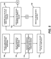
- the load cells 15 of the scale 5 are selected as the component to be monitored 100 and a diagnostic parameter (e.g., temperature, digital signal voltage, supply voltage, or zero balance change) of the individual load cells 15 of the vehicle weighing scale 5 is selected to be monitored 105.
- a diagnostic parameter e.g., temperature, digital signal voltage, supply voltage, or zero balance change
- Appropriate diagnostic parameter signals from the load cells 15 are received 110 by the computer device (e.g., terminal) 25.
- a standard statistical test can be applied to determine if any of the diagnostic parameter values from each load cell 15 is an outlier (i.e., sample data that is unusually far from the other observations). Several such statistical tests exist and would be well known to those of skill in the art.
- a comparison can be made120 to the number of standard deviations that correspond to the bounds of the probability band around the mean (i.e., the Z-value from the standard normal Z-table associated with the defined probability P). If the probability band is not exceeded 125 (i.e., Z-Value ⁇ Dmax), then no problem is indicated and the process returns to the point of receiving a new set of diagnostic parameter signals 110 from all of the load cells 15. If the probability band is exceeded 125 (i.e., Dmax > Z-Value), then a problem with that load cell is indicated 130.
- the expected temperature spread can be used to set a limit on the amount by which the temperatures of any two given load cells 15 may differ. When the temperature spread between any two load cells exceeds this limit, a problem may be indicated and an alert, such as an alarm, may be triggered.
- a statistical test can be applied to determine if the temperature of any load cell is a statistical outlier compared to the temperatures of the other load cells.
- a load cell whose temperature is determined to be a statistical outlier may be indicative of a problem with that load cell 15 and may trigger an alert, such as an alarm.
- Comparing the load cell temperature of a given load cell to the temperature of each of the other load cells of the scale or to a median load cell temperature, or identifying outlying load cell temperatures by statistical analysis eliminates the need for determining and then setting a threshold around the monitored operating parameter itself (i.e., a range of acceptable individual load cell temperatures in this case), which allows the diagnostic parameter comparison to better adapt to changing conditions. This is useful, because in one case a given load cell temperature reading may be indicative of a problem while in another case the same temperature reading may not be indicative of a problem.
- the temperature of the ten load cells 15 of the vehicle weighing scale 5 are 20.1° C, 19.7° C, 20.5° C, 20.2° C, 20.9° C, 20.7° C, 19.9° C, 21.0° C, 20.6° C and 33.2° C.
- the minimum and maximum load cell operating temperatures are -10° C and 40° C, respectively.
- known diagnostic techniques might very well adopt the -10° C and 40° C temperatures as lower and upper diagnostic threshold values for each of the load cells 15. Consequently, no indication of a faulty load cell would be given in this example despite the significantly different temperature of one of the load cells 15, because all of the load cell temperatures are within the allowed threshold values.
- the 33.2° C temperature reading may be identified as an outlier by one or more of the aforementioned statistical tests for identifying outliers.
- Applying the aforementioned Chauvenet's Criterion to this example reveals that the value of Dmax for the load cell associated with the 33.2° C temperature exceeds the expected Z-Value (i.e., 2.83 > 1.96), thereby identifying the 33.2° C temperature as an outlier.
- the outlying temperature of the given load cell may indicate a problem with that load cell (e.g., a failing temperature sensor) and may trigger an indicator, such as an alarm, before an actual cell failure (e.g., an inaccurate weight output) occurs.
- the expected supply voltage spread can be used to set a limit on the amount by which the supply voltages of any two given load cells 15 may differ. When the supply voltage spread between any two load cells exceeds this limit, a problem may be indicated and an alert, such as an alarm, may be triggered.
- a median load cell supply voltage value may be calculated from the supply voltages of all the load cells, and the deviation of the supply voltage of each load cell from the median supply voltage may be determined.
- a load cell whose supply voltage deviates from the median supply voltage by more than a predetermined maximum supply voltage deviation value may be indicative of a problem with that load cell 15 and may trigger an alert, such as an alarm.
- a statistical test can be applied to determine if the supply voltage of any load cell is a statistical outlier compared to the supply voltage of the other load cells.
- a load cell whose supply voltage is determined to be a statistical outlier may be indicative of a problem with that load cell 15 and may trigger an alert, such as an alarm.
- Comparing the supply voltage of a given load cell to the supply voltage of each of the other load cells of the scale or to a median load cell supply voltage, or identifying outlying load cell supply voltages by statistical analysis eliminates the need for determining and then setting a threshold around the operating parameter itself (i.e., a range of acceptable individual load cell supply voltages in this case), which allows the diagnostic parameter comparison to better adapt to changing conditions. This is useful, because in one case a given load cell supply voltage reading may be indicative of a problem while in another case the same supply voltage reading may not be indicative of a problem.
- expected supply voltage spread data may be used to set a limit on the amount that the supply voltage of any one load cell may differ from the supply voltage of another load cell, or to set a limit on the maximum amount the supply voltage of any load cell may deviate from the median load cell supply voltage, without indicating a problem with that load cell.
- the supply voltage spread between any two load cells may not be permitted to differ by more than 5V or the supply voltage of a given load cell may not be permitted to deviate by more than 5V from the median load cell supply voltage, without being identified as an outlier.
- the outlying supply voltage of the given load cell may indicate a problem with that load cell (e.g., a damaged cable) and may trigger an indicator, such as an alarm, before an actual cell failure (e.g., no weight output due to insufficient voltage) occurs.
- the 8.2V supply voltage reading may be identified as an outlier by one or more of the aforementioned statistical tests for identifying outliers.
- the value of Dmax for the load cell associated with the 8.2V supply voltage exceeds the expected Z-Value (i.e., 2.83 > 1.96) and identifies the 8.2V supply voltage as an outlier.
- the outlying supply voltage of the given load cell may indicate a problem with that load cell (e.g., a damaged cable) and may trigger an indicator, such as an alarm, before an actual cell failure (e.g., no weight output due to insufficient voltage) occurs.
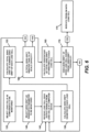
- the load cells 15 of the scale 5 are selected as the component to be monitored 135 and the zero balance change of the individual load cells 15 of the vehicle weighing scale 5 is selected as the diagnostic parameter to be monitored 140.
- Appropriate signals from the load cells 15 are received 145 by the computer device (e.g., terminal) 25.
- the zero balance procedure involves obtaining a force measuring device output value for each force measuring device of a scale and also a sum of all the force measuring device output values, while the scale is in an unloaded state. Therefore, during the zero balance calibration process for the vehicle weighing scale 5, a zero balance reading for each individual load cell 15 is stored at the terminal 25 and/or otherwise, as is a zero balance reading for the entire scale (i.e., a cumulative value for all of the load cells). Also, each time a scale zero command is issued, the scale is assumed to be in a no load condition.
- the zero balance change of the individual load cells 15 may be more accurately described as a zero drift error.
- a zero drift error may only be recognized, for example, if a zero command is issued (either manually or during the scale power-up process), the scale is not in motion, the zero is in the zero capture range (a set range around the original zero condition for the scale), the total zero drift is above 1% of the scale capacity (a value determined based on the design of the exemplary vehicle weighing scale 5 and the load cells 15 employed), and the acceptable zero drift threshold is exceeded for an individual load cell.
- the zero drift for each load cell 15 is determined by comparing the current zero reading of the load cell with the zero reading obtained during scale calibration 150. The absolute value differences between the current zero reading and the calibrated zero reading of each load cell are then summed to obtain a Total Zero Drift value 155 for the vehicle weighing scale 5. The calculated Total Zero Drift is then compared to a predetermined percentage of the scale capacity 160. In this particular example, if the calculated Total Zero Drift value for the vehicle weighing scale divided by the scale capacity is greater than 1%, the diagnostic method continues to a first step 165 of a second test.
- the comparison of Total Zero Drift to scale capacity may be represented as: IF Total Zero Drift/Scale Capacity > 1 % THEN Continue to Test 2
- the second test is used to determine whether one or a small number of the load cells 15 of the vehicle weighing scale 5 account for the majority of the Total Zero Drift. If each load cell exhibits an approximately equal amount of the Total Zero Drift (i.e., each load cell exhibits a similar amount of zero drift), it is likely that any calculated zero drift is not indicative of a problem with the load cells, but due to another factor such as for example, a simple accumulation or removal of dust, snow, ice, etc., from the scale deck 10. In contrast, if only one or a small number (e.g., two load cells) account for a large percentage of the Total Zero Drift, a load cell problem is likely and should be indicated, whether by an alarm or otherwise.
- a small number e.g., two load cells
- this diagnostic method is based on a comparison of the selected diagnostic parameter values of all the similar components (load cells 15) in the system (weighing scale 5).
- a first step 165 of the second test is operative in this case to calculate percentage of Total Zero Drift attributable to each load cell.
- the second step 170 of the second test determines whether the percentage of Total Zero Drift attributable to a given load cell exceeds some preset zero drift threshold value.
- Diagnostic method embodiments according to the invention are implemented on and by a computer device having a processor executing appropriate instructions.
- the processor may be associated with a software program(s) for this purpose.
- the computer device is a scale terminal which, as would be familiar to one of skill in the art, is a device that is in electronic communication with a scale and the force measuring devices thereof and may function to control the scale, display weight readings, display diagnostic information, etc.
- Two non-limiting examples of such a terminal are the IND560 PDX Terminal and the IND780 Terminal, both available from Mettler-Toledo, LLC in Columbus, Ohio.
- diagnostic methods according to the invention may be carried out on a computer device that is separate from the scale terminal, and which may or may not be in communication therewith.
- the computer device receives output signals from a plurality of like components (e.g., force measuring devices) of a given weighing scale that are indicative of the selected diagnostic parameter, evaluates the signals relating to a selected diagnostic parameter associated with the like components to identify outliers and, when an outlier(s) is detected, indicates a problem with the component(s) from which the outlying output was received and/or takes some other action.
- the processor of the computer device or a software program executed by the processor is provided with the appropriate formulas and threshold or other values necessary to perform any comparisons, evaluations and analysis.
Landscapes
- Physics & Mathematics (AREA)
- General Physics & Mathematics (AREA)
- Engineering & Computer Science (AREA)
- Computer Networks & Wireless Communication (AREA)
- Measurement Of Force In General (AREA)
- Force Measurement Appropriate To Specific Purposes (AREA)
- Testing And Monitoring For Control Systems (AREA)
- Measuring Volume Flow (AREA)
- Measurement Of Current Or Voltage (AREA)
- Investigating Or Analyzing Materials Using Thermal Means (AREA)
Applications Claiming Priority (3)
| Application Number | Priority Date | Filing Date | Title |
|---|---|---|---|
| US14/337,127 US9587974B2 (en) | 2014-07-21 | 2014-07-21 | Weighing scale diagnostics method |
| EP15745332.5A EP3172540B1 (en) | 2014-07-21 | 2015-07-20 | Weighing scale diagnostics method |
| PCT/US2015/041158 WO2016014421A1 (en) | 2014-07-21 | 2015-07-20 | Weighing scale diagnostics method |
Related Parent Applications (2)
| Application Number | Title | Priority Date | Filing Date |
|---|---|---|---|
| EP15745332.5A Division EP3172540B1 (en) | 2014-07-21 | 2015-07-20 | Weighing scale diagnostics method |
| EP15745332.5A Division-Into EP3172540B1 (en) | 2014-07-21 | 2015-07-20 | Weighing scale diagnostics method |
Publications (2)
| Publication Number | Publication Date |
|---|---|
| EP3940352A1 EP3940352A1 (en) | 2022-01-19 |
| EP3940352B1 true EP3940352B1 (en) | 2023-06-07 |
Family
ID=53773553
Family Applications (2)
| Application Number | Title | Priority Date | Filing Date |
|---|---|---|---|
| EP15745332.5A Active EP3172540B1 (en) | 2014-07-21 | 2015-07-20 | Weighing scale diagnostics method |
| EP21193693.5A Active EP3940352B1 (en) | 2014-07-21 | 2015-07-20 | Weighing scale diagnostics method |
Family Applications Before (1)
| Application Number | Title | Priority Date | Filing Date |
|---|---|---|---|
| EP15745332.5A Active EP3172540B1 (en) | 2014-07-21 | 2015-07-20 | Weighing scale diagnostics method |
Country Status (11)
| Country | Link |
|---|---|
| US (2) | US9587974B2 (ru) |
| EP (2) | EP3172540B1 (ru) |
| JP (1) | JP2017521670A (ru) |
| CN (1) | CN107076607B (ru) |
| AU (2) | AU2015292882B2 (ru) |
| BR (1) | BR112017000843B1 (ru) |
| CA (1) | CA2952302C (ru) |
| DK (2) | DK3172540T3 (ru) |
| MX (1) | MX359990B (ru) |
| RU (1) | RU2017105159A (ru) |
| WO (1) | WO2016014421A1 (ru) |
Families Citing this family (19)
| Publication number | Priority date | Publication date | Assignee | Title |
|---|---|---|---|---|
| CN103852144B (zh) * | 2012-12-04 | 2016-04-13 | 梅特勒-托利多(常州)精密仪器有限公司 | 具有不间断称重功能的称重系统以及称重方法 |
| JP6443356B2 (ja) * | 2016-01-29 | 2018-12-26 | オムロン株式会社 | ロードセル入力ユニット |
| CN107645478B (zh) * | 2016-07-22 | 2020-12-22 | 阿里巴巴集团控股有限公司 | 网络攻击防御系统、方法及装置 |
| US10371566B1 (en) * | 2016-12-30 | 2019-08-06 | Air Liquide Electronics U.S. Lp | Load cell failure detection and delayed repair |
| CN108692801B (zh) * | 2017-04-12 | 2022-01-28 | 梅特勒-托利多(常州)精密仪器有限公司 | 称重测量系统及计量系统 |
| CN108303167A (zh) * | 2018-01-04 | 2018-07-20 | 中联重科股份有限公司 | 物料称重控制设备、系统及方法 |
| CN107990968B (zh) * | 2018-01-23 | 2020-01-17 | 山东钢铁股份有限公司 | 一种高炉槽下料斗秤的校核方法 |
| CN110154242B (zh) * | 2018-03-29 | 2020-02-18 | 衢州市质量技术监督检测中心 | 一种混凝土配料秤载荷检定方法 |
| JP2019208482A (ja) * | 2018-06-08 | 2019-12-12 | シャープ株式会社 | 制御装置、動物用トイレ、情報処理装置、情報処理端末、制御プログラム及び制御方法 |
| US11022721B2 (en) * | 2018-06-15 | 2021-06-01 | Wisys Technology Foundation, Inc. | Spatially diverse snowpack sensing system |
| FR3101191B1 (fr) * | 2019-09-25 | 2023-05-12 | Schneider Electric Ind Sas | Détermination d’un état d’un appareil de coupure |
| CN110987139B (zh) * | 2019-12-31 | 2022-05-17 | 上海华羿汽车系统集成有限公司 | 一种车辆最大载质量的确定方法、车辆、设备和存储介质 |
| CN113588062B (zh) * | 2020-04-30 | 2024-02-02 | 梅特勒-托利多(常州)测量技术有限公司 | 检重设备干扰测量方法和系统 |
| CN111693125B (zh) * | 2020-06-11 | 2022-03-08 | 深圳市美新特智能装备有限公司 | 一种高精度动态称重设备的称台长度计算方法及其系统 |
| DE102020004838A1 (de) * | 2020-08-07 | 2022-02-10 | Mettler-Toledo Gmbh | Verfahren und Vorrichtung zur sensorischen Messung einer Stoffprobe |
| CN112304413A (zh) * | 2020-09-28 | 2021-02-02 | 梅特勒-托利多(常州)精密仪器有限公司 | 称重传感器的状态检测方法和装置 |
| US11796381B1 (en) * | 2020-11-07 | 2023-10-24 | Greater Goods, LLC | Weight verification and tare process for scale |
| CN112763037B (zh) * | 2020-12-30 | 2023-06-06 | 北京万集科技股份有限公司 | 称重设备监测系统及其监测方法 |
| CN113063482A (zh) * | 2021-03-25 | 2021-07-02 | 梅特勒-托利多(常州)精密仪器有限公司 | 高空作业平台称重传感器的零漂检测方法和系统 |
Family Cites Families (27)
| Publication number | Priority date | Publication date | Assignee | Title |
|---|---|---|---|---|
| US4804052A (en) * | 1987-11-30 | 1989-02-14 | Toledo Scale Corporation | Compensated multiple load cell scale |
| US4909338A (en) * | 1989-06-12 | 1990-03-20 | Ncr Corporation | Method and apparatus for scale calibration and weighing |
| US5296655A (en) * | 1992-02-10 | 1994-03-22 | Beowulf Corporation | Control system for multiple input scales |
| JP3199129B2 (ja) * | 1992-03-23 | 2001-08-13 | 大和製衡株式会社 | 力または荷重センサの故障自己復帰装置 |
| JP3112565B2 (ja) * | 1992-05-22 | 2000-11-27 | 大和製衡株式会社 | トラックスケールの故障診断システム |
| US6112162A (en) * | 1997-07-11 | 2000-08-29 | Richards; James L. | Weight measuring apparatus using a plurality of sensors |
| US6260003B1 (en) * | 1998-12-11 | 2001-07-10 | Cardinal Scale Manufacturing Company | Statistical compensation of load position on a platform scale |
| DE19860294A1 (de) * | 1998-12-18 | 2000-06-21 | Francotyp Postalia Gmbh | Verfahren und Anordnung zum Bestimmen eines Gewichts mit einer dynamischen Waage |
| JP4693950B2 (ja) * | 1999-12-08 | 2011-06-01 | 大和製衡株式会社 | 計量システム |
| DE10041251B4 (de) * | 2000-08-23 | 2010-03-11 | HBM Wägetechnik GmbH | Eichfähiges Wägesystem und Verfahren zur Ermittlung eichpflichtiger Meßwertdaten |
| US6576849B2 (en) * | 2000-12-01 | 2003-06-10 | Mettler-Toledo, Inc. | Load cell diagnostics and failure prediction weighing apparatus and process |
| DE10120978A1 (de) | 2001-05-01 | 2002-11-14 | Bizerba Gmbh & Co Kg | Vorrichtung und Verfahren zur Erfassung und Aufbereitung von auf einen Fahrzeugsitz wirkenden Gewichtskräften |
| US6801866B1 (en) * | 2001-06-15 | 2004-10-05 | John C. Yarian | Method for minimizing error in weighing devices |
| US6552278B2 (en) * | 2001-09-10 | 2003-04-22 | Weigh-Tronix Inc. | Multiple load sensing multi-load cell scale and method |
| US6919516B2 (en) * | 2002-01-08 | 2005-07-19 | Mettler-Toledo | RF multiple load cell scale |
| JP4642504B2 (ja) * | 2005-02-21 | 2011-03-02 | 大和製衡株式会社 | 重量測定装置 |
| JP2010531553A (ja) | 2007-03-30 | 2010-09-24 | ネットクオス・インコーポレーテッド | ネットワーク異常検出のための統計的方法およびシステム |
| BRPI0812225B1 (pt) * | 2007-06-07 | 2018-10-30 | Mettler Toledo Ag | método de monitorar a condição de um dispositivo de medição de força, dispositivo de medição de força e módulo de medição de força. |
| AU2008258813B2 (en) * | 2007-06-07 | 2013-10-10 | Mettler-Toledo Gmbh | Multiple-force-measuring device, force-measuring module, and method for status monitoring |
| CN101206136B (zh) * | 2007-12-06 | 2013-06-19 | 云南昆船电子设备有限公司 | 可自检的电子皮带秤的称重方法 |
| CN101532872B (zh) * | 2009-04-22 | 2010-12-29 | 江苏赛摩集团有限公司 | 一种电子皮带秤的称量控制装置及其方法 |
| CN101922960B (zh) * | 2009-06-12 | 2012-04-25 | 铜陵市三爱思电子有限公司 | 用于对连续散料称重的皮带运输机计量方法及其装置 |
| US8237066B2 (en) * | 2009-12-30 | 2012-08-07 | Mettler-Toledo, LLC | Weighing apparatus employing load cells of different capacity |
| JP5704982B2 (ja) * | 2011-03-15 | 2015-04-22 | 大和製衡株式会社 | ホッパ式計量装置 |
| JP5777407B2 (ja) | 2011-05-30 | 2015-09-09 | 大和製衡株式会社 | コンベヤスケール |
| CN202267529U (zh) * | 2011-09-21 | 2012-06-06 | 博爱县电业公司 | 一种电力皮带秤校验装置 |
| CN103852144B (zh) * | 2012-12-04 | 2016-04-13 | 梅特勒-托利多(常州)精密仪器有限公司 | 具有不间断称重功能的称重系统以及称重方法 |
-
2014
- 2014-07-21 US US14/337,127 patent/US9587974B2/en active Active
-
2015
- 2015-07-20 JP JP2017503592A patent/JP2017521670A/ja active Pending
- 2015-07-20 CA CA2952302A patent/CA2952302C/en active Active
- 2015-07-20 WO PCT/US2015/041158 patent/WO2016014421A1/en active Application Filing
- 2015-07-20 DK DK15745332.5T patent/DK3172540T3/da active
- 2015-07-20 EP EP15745332.5A patent/EP3172540B1/en active Active
- 2015-07-20 MX MX2016016863A patent/MX359990B/es active IP Right Grant
- 2015-07-20 BR BR112017000843-2A patent/BR112017000843B1/pt active IP Right Grant
- 2015-07-20 RU RU2017105159A patent/RU2017105159A/ru not_active Application Discontinuation
- 2015-07-20 DK DK21193693.5T patent/DK3940352T3/da active
- 2015-07-20 AU AU2015292882A patent/AU2015292882B2/en active Active
- 2015-07-20 CN CN201580040149.5A patent/CN107076607B/zh active Active
- 2015-07-20 EP EP21193693.5A patent/EP3940352B1/en active Active
-
2017
- 2017-03-06 US US15/450,967 patent/US10527486B2/en active Active
-
2020
- 2020-09-21 AU AU2020239630A patent/AU2020239630B2/en active Active
Also Published As
| Publication number | Publication date |
|---|---|
| US10527486B2 (en) | 2020-01-07 |
| MX359990B (es) | 2018-10-18 |
| CA2952302A1 (en) | 2016-01-28 |
| RU2017105159A3 (ru) | 2019-01-18 |
| MX2016016863A (es) | 2017-04-25 |
| CA2952302C (en) | 2023-09-05 |
| DK3172540T3 (da) | 2021-12-20 |
| AU2015292882A1 (en) | 2017-01-12 |
| US20160018254A1 (en) | 2016-01-21 |
| EP3940352A1 (en) | 2022-01-19 |
| US20170176242A1 (en) | 2017-06-22 |
| DK3940352T3 (da) | 2023-09-04 |
| RU2017105159A (ru) | 2018-08-22 |
| AU2020239630B2 (en) | 2021-03-04 |
| AU2015292882B2 (en) | 2020-10-22 |
| JP2017521670A (ja) | 2017-08-03 |
| AU2020239630A1 (en) | 2020-10-29 |
| EP3172540A1 (en) | 2017-05-31 |
| CN107076607B (zh) | 2020-08-04 |
| US9587974B2 (en) | 2017-03-07 |
| WO2016014421A1 (en) | 2016-01-28 |
| CN107076607A (zh) | 2017-08-18 |
| EP3172540B1 (en) | 2021-10-27 |
| BR112017000843B1 (pt) | 2022-03-29 |
| BR112017000843A2 (pt) | 2017-12-05 |
Similar Documents
| Publication | Publication Date | Title |
|---|---|---|
| AU2020239630B2 (en) | Weighing scale diagnostics method | |
| US7930112B2 (en) | Method for evaluating measured values for identifying a material fatigue | |
| US8965712B2 (en) | Life predicting method for solder joint, life predicting apparatus for solder joint and electronic device | |
| WO2016055016A1 (zh) | 称重传感器、称重网络及监测方法 | |
| KR101218589B1 (ko) | 로드셀 모니터링 장치 및 방법 | |
| EP3759462B1 (en) | High precision weighing system and weighing method, thermogravimetric analyser and storage medium | |
| EP2743667B1 (en) | Load cell residual fatigue life estimation system and method | |
| JP5621967B2 (ja) | 異常データ分析システム | |
| EP2133665B1 (en) | System and method for objective self-diagnosis of measurement device calibration condition | |
| US7514941B2 (en) | Method and apparatus for predicting the reliability of electronic systems | |
| CN110582626A (zh) | 用由磨损因子校正的异常检测来监视涡轮机的系统和方法 | |
| JP5704982B2 (ja) | ホッパ式計量装置 | |
| KR102501286B1 (ko) | 기체 센서의 이상 감지 장치 및 방법 | |
| EP4105856A1 (en) | Method for evaluating remaining life of component, functional module and system | |
| US20180088570A1 (en) | Method for monitoring the function of a sensor arrangement | |
| JP2012014222A (ja) | センサ状態判定装置 | |
| KR102252178B1 (ko) | 머신 러닝 기법을 적용한 불량 셀 검출 방법 | |
| CN113884258B (zh) | 一种考虑温度对桥梁刚度影响的检验系数修正方法 | |
| JP7287858B2 (ja) | 構造物劣化診断システム | |
| JP5679837B2 (ja) | 計量装置 | |
| CN116226966A (zh) | 桥梁承载能力的确定方法、装置、存储介质及电子装置 | |
| KR20200111956A (ko) | 로드 모니터링 장치 및 방법 | |
| CN116964230A (zh) | 高炉的异常判定装置、高炉的异常判定方法、高炉的运行方法、高炉异常判定系统、异常判定服务器装置、显示终端装置、异常判定服务器装置的程序以及显示终端装置的程序 |
Legal Events
| Date | Code | Title | Description |
|---|---|---|---|
| PUAI | Public reference made under article 153(3) epc to a published international application that has entered the european phase |
Free format text: ORIGINAL CODE: 0009012 |
|
| STAA | Information on the status of an ep patent application or granted ep patent |
Free format text: STATUS: THE APPLICATION HAS BEEN PUBLISHED |
|
| AC | Divisional application: reference to earlier application |
Ref document number: 3172540 Country of ref document: EP Kind code of ref document: P |
|
| AK | Designated contracting states |
Kind code of ref document: A1 Designated state(s): AL AT BE BG CH CY CZ DE DK EE ES FI FR GB GR HR HU IE IS IT LI LT LU LV MC MK MT NL NO PL PT RO RS SE SI SK SM TR |
|
| STAA | Information on the status of an ep patent application or granted ep patent |
Free format text: STATUS: REQUEST FOR EXAMINATION WAS MADE |
|
| 17P | Request for examination filed |
Effective date: 20220714 |
|
| RBV | Designated contracting states (corrected) |
Designated state(s): AL AT BE BG CH CY CZ DE DK EE ES FI FR GB GR HR HU IE IS IT LI LT LU LV MC MK MT NL NO PL PT RO RS SE SI SK SM TR |
|
| STAA | Information on the status of an ep patent application or granted ep patent |
Free format text: STATUS: EXAMINATION IS IN PROGRESS |
|
| 17Q | First examination report despatched |
Effective date: 20221110 |
|
| GRAP | Despatch of communication of intention to grant a patent |
Free format text: ORIGINAL CODE: EPIDOSNIGR1 |
|
| STAA | Information on the status of an ep patent application or granted ep patent |
Free format text: STATUS: GRANT OF PATENT IS INTENDED |
|
| INTG | Intention to grant announced |
Effective date: 20230116 |
|
| GRAS | Grant fee paid |
Free format text: ORIGINAL CODE: EPIDOSNIGR3 |
|
| GRAA | (expected) grant |
Free format text: ORIGINAL CODE: 0009210 |
|
| STAA | Information on the status of an ep patent application or granted ep patent |
Free format text: STATUS: THE PATENT HAS BEEN GRANTED |
|
| AC | Divisional application: reference to earlier application |
Ref document number: 3172540 Country of ref document: EP Kind code of ref document: P |
|
| AK | Designated contracting states |
Kind code of ref document: B1 Designated state(s): AL AT BE BG CH CY CZ DE DK EE ES FI FR GB GR HR HU IE IS IT LI LT LU LV MC MK MT NL NO PL PT RO RS SE SI SK SM TR |
|
| REG | Reference to a national code |
Ref country code: GB Ref legal event code: FG4D |
|
| REG | Reference to a national code |
Ref country code: CH Ref legal event code: EP Ref country code: AT Ref legal event code: REF Ref document number: 1576417 Country of ref document: AT Kind code of ref document: T Effective date: 20230615 |
|
| REG | Reference to a national code |
Ref country code: DE Ref legal event code: R096 Ref document number: 602015084156 Country of ref document: DE |
|
| REG | Reference to a national code |
Ref country code: DK Ref legal event code: T3 Effective date: 20230829 |
|
| REG | Reference to a national code |
Ref country code: NO Ref legal event code: T2 Effective date: 20230607 |
|
| REG | Reference to a national code |
Ref country code: SE Ref legal event code: TRGR |
|
| REG | Reference to a national code |
Ref country code: LT Ref legal event code: MG9D |
|
| REG | Reference to a national code |
Ref country code: NL Ref legal event code: MP Effective date: 20230607 |
|
| PG25 | Lapsed in a contracting state [announced via postgrant information from national office to epo] |
Ref country code: ES Free format text: LAPSE BECAUSE OF FAILURE TO SUBMIT A TRANSLATION OF THE DESCRIPTION OR TO PAY THE FEE WITHIN THE PRESCRIBED TIME-LIMIT Effective date: 20230607 |
|
| PGFP | Annual fee paid to national office [announced via postgrant information from national office to epo] |
Ref country code: NO Payment date: 20230719 Year of fee payment: 9 |
|
| REG | Reference to a national code |
Ref country code: AT Ref legal event code: MK05 Ref document number: 1576417 Country of ref document: AT Kind code of ref document: T Effective date: 20230607 |
|
| PG25 | Lapsed in a contracting state [announced via postgrant information from national office to epo] |
Ref country code: RS Free format text: LAPSE BECAUSE OF FAILURE TO SUBMIT A TRANSLATION OF THE DESCRIPTION OR TO PAY THE FEE WITHIN THE PRESCRIBED TIME-LIMIT Effective date: 20230607 Ref country code: NL Free format text: LAPSE BECAUSE OF FAILURE TO SUBMIT A TRANSLATION OF THE DESCRIPTION OR TO PAY THE FEE WITHIN THE PRESCRIBED TIME-LIMIT Effective date: 20230607 Ref country code: LV Free format text: LAPSE BECAUSE OF FAILURE TO SUBMIT A TRANSLATION OF THE DESCRIPTION OR TO PAY THE FEE WITHIN THE PRESCRIBED TIME-LIMIT Effective date: 20230607 Ref country code: LT Free format text: LAPSE BECAUSE OF FAILURE TO SUBMIT A TRANSLATION OF THE DESCRIPTION OR TO PAY THE FEE WITHIN THE PRESCRIBED TIME-LIMIT Effective date: 20230607 Ref country code: HR Free format text: LAPSE BECAUSE OF FAILURE TO SUBMIT A TRANSLATION OF THE DESCRIPTION OR TO PAY THE FEE WITHIN THE PRESCRIBED TIME-LIMIT Effective date: 20230607 Ref country code: GR Free format text: LAPSE BECAUSE OF FAILURE TO SUBMIT A TRANSLATION OF THE DESCRIPTION OR TO PAY THE FEE WITHIN THE PRESCRIBED TIME-LIMIT Effective date: 20230908 |
|
| PGFP | Annual fee paid to national office [announced via postgrant information from national office to epo] |
Ref country code: DK Payment date: 20230830 Year of fee payment: 9 |
|
| PG25 | Lapsed in a contracting state [announced via postgrant information from national office to epo] |
Ref country code: FI Free format text: LAPSE BECAUSE OF FAILURE TO SUBMIT A TRANSLATION OF THE DESCRIPTION OR TO PAY THE FEE WITHIN THE PRESCRIBED TIME-LIMIT Effective date: 20230607 |
|
| PG25 | Lapsed in a contracting state [announced via postgrant information from national office to epo] |
Ref country code: SK Free format text: LAPSE BECAUSE OF FAILURE TO SUBMIT A TRANSLATION OF THE DESCRIPTION OR TO PAY THE FEE WITHIN THE PRESCRIBED TIME-LIMIT Effective date: 20230607 |
|
| PG25 | Lapsed in a contracting state [announced via postgrant information from national office to epo] |
Ref country code: IS Free format text: LAPSE BECAUSE OF FAILURE TO SUBMIT A TRANSLATION OF THE DESCRIPTION OR TO PAY THE FEE WITHIN THE PRESCRIBED TIME-LIMIT Effective date: 20231007 |
|
| PG25 | Lapsed in a contracting state [announced via postgrant information from national office to epo] |
Ref country code: SM Free format text: LAPSE BECAUSE OF FAILURE TO SUBMIT A TRANSLATION OF THE DESCRIPTION OR TO PAY THE FEE WITHIN THE PRESCRIBED TIME-LIMIT Effective date: 20230607 Ref country code: SK Free format text: LAPSE BECAUSE OF FAILURE TO SUBMIT A TRANSLATION OF THE DESCRIPTION OR TO PAY THE FEE WITHIN THE PRESCRIBED TIME-LIMIT Effective date: 20230607 Ref country code: RO Free format text: LAPSE BECAUSE OF FAILURE TO SUBMIT A TRANSLATION OF THE DESCRIPTION OR TO PAY THE FEE WITHIN THE PRESCRIBED TIME-LIMIT Effective date: 20230607 Ref country code: PT Free format text: LAPSE BECAUSE OF FAILURE TO SUBMIT A TRANSLATION OF THE DESCRIPTION OR TO PAY THE FEE WITHIN THE PRESCRIBED TIME-LIMIT Effective date: 20231009 Ref country code: IS Free format text: LAPSE BECAUSE OF FAILURE TO SUBMIT A TRANSLATION OF THE DESCRIPTION OR TO PAY THE FEE WITHIN THE PRESCRIBED TIME-LIMIT Effective date: 20231007 Ref country code: EE Free format text: LAPSE BECAUSE OF FAILURE TO SUBMIT A TRANSLATION OF THE DESCRIPTION OR TO PAY THE FEE WITHIN THE PRESCRIBED TIME-LIMIT Effective date: 20230607 Ref country code: CZ Free format text: LAPSE BECAUSE OF FAILURE TO SUBMIT A TRANSLATION OF THE DESCRIPTION OR TO PAY THE FEE WITHIN THE PRESCRIBED TIME-LIMIT Effective date: 20230607 Ref country code: AT Free format text: LAPSE BECAUSE OF FAILURE TO SUBMIT A TRANSLATION OF THE DESCRIPTION OR TO PAY THE FEE WITHIN THE PRESCRIBED TIME-LIMIT Effective date: 20230607 |
|
| REG | Reference to a national code |
Ref country code: DE Ref legal event code: R119 Ref document number: 602015084156 Country of ref document: DE |
|
| PG25 | Lapsed in a contracting state [announced via postgrant information from national office to epo] |
Ref country code: PL Free format text: LAPSE BECAUSE OF FAILURE TO SUBMIT A TRANSLATION OF THE DESCRIPTION OR TO PAY THE FEE WITHIN THE PRESCRIBED TIME-LIMIT Effective date: 20230607 |
|
| REG | Reference to a national code |
Ref country code: CH Ref legal event code: PL |
|
| PG25 | Lapsed in a contracting state [announced via postgrant information from national office to epo] |
Ref country code: MC Free format text: LAPSE BECAUSE OF FAILURE TO SUBMIT A TRANSLATION OF THE DESCRIPTION OR TO PAY THE FEE WITHIN THE PRESCRIBED TIME-LIMIT Effective date: 20230607 |
|
| REG | Reference to a national code |
Ref country code: BE Ref legal event code: MM Effective date: 20230731 |
|
| PG25 | Lapsed in a contracting state [announced via postgrant information from national office to epo] |
Ref country code: LU Free format text: LAPSE BECAUSE OF NON-PAYMENT OF DUE FEES Effective date: 20230720 |
|
| PG25 | Lapsed in a contracting state [announced via postgrant information from national office to epo] |
Ref country code: MC Free format text: LAPSE BECAUSE OF FAILURE TO SUBMIT A TRANSLATION OF THE DESCRIPTION OR TO PAY THE FEE WITHIN THE PRESCRIBED TIME-LIMIT Effective date: 20230607 Ref country code: LU Free format text: LAPSE BECAUSE OF NON-PAYMENT OF DUE FEES Effective date: 20230720 |
|
| PLBE | No opposition filed within time limit |
Free format text: ORIGINAL CODE: 0009261 |
|
| STAA | Information on the status of an ep patent application or granted ep patent |
Free format text: STATUS: NO OPPOSITION FILED WITHIN TIME LIMIT |
|
| REG | Reference to a national code |
Ref country code: IE Ref legal event code: MM4A |
|
| PG25 | Lapsed in a contracting state [announced via postgrant information from national office to epo] |
Ref country code: DE Free format text: LAPSE BECAUSE OF NON-PAYMENT OF DUE FEES Effective date: 20240201 Ref country code: CH Free format text: LAPSE BECAUSE OF NON-PAYMENT OF DUE FEES Effective date: 20230731 |
|
| PG25 | Lapsed in a contracting state [announced via postgrant information from national office to epo] |
Ref country code: SI Free format text: LAPSE BECAUSE OF FAILURE TO SUBMIT A TRANSLATION OF THE DESCRIPTION OR TO PAY THE FEE WITHIN THE PRESCRIBED TIME-LIMIT Effective date: 20230607 |
|
| 26N | No opposition filed |
Effective date: 20240308 |
|
| GBPC | Gb: european patent ceased through non-payment of renewal fee |
Effective date: 20230907 |
|
| PG25 | Lapsed in a contracting state [announced via postgrant information from national office to epo] |
Ref country code: SI Free format text: LAPSE BECAUSE OF FAILURE TO SUBMIT A TRANSLATION OF THE DESCRIPTION OR TO PAY THE FEE WITHIN THE PRESCRIBED TIME-LIMIT Effective date: 20230607 Ref country code: IT Free format text: LAPSE BECAUSE OF FAILURE TO SUBMIT A TRANSLATION OF THE DESCRIPTION OR TO PAY THE FEE WITHIN THE PRESCRIBED TIME-LIMIT Effective date: 20230607 Ref country code: BE Free format text: LAPSE BECAUSE OF NON-PAYMENT OF DUE FEES Effective date: 20230731 |
|
| PG25 | Lapsed in a contracting state [announced via postgrant information from national office to epo] |
Ref country code: IE Free format text: LAPSE BECAUSE OF NON-PAYMENT OF DUE FEES Effective date: 20230720 |
|
| PG25 | Lapsed in a contracting state [announced via postgrant information from national office to epo] |
Ref country code: GB Free format text: LAPSE BECAUSE OF NON-PAYMENT OF DUE FEES Effective date: 20230907 |
|
| PG25 | Lapsed in a contracting state [announced via postgrant information from national office to epo] |
Ref country code: IE Free format text: LAPSE BECAUSE OF NON-PAYMENT OF DUE FEES Effective date: 20230720 Ref country code: GB Free format text: LAPSE BECAUSE OF NON-PAYMENT OF DUE FEES Effective date: 20230907 Ref country code: FR Free format text: LAPSE BECAUSE OF NON-PAYMENT OF DUE FEES Effective date: 20230807 |