EP3940134B1 - Élément bâti destiné à un dispositif de traitement des vêtements et dispositif de traitement des vêtements - Google Patents
Élément bâti destiné à un dispositif de traitement des vêtements et dispositif de traitement des vêtements Download PDFInfo
- Publication number
- EP3940134B1 EP3940134B1 EP19945958.7A EP19945958A EP3940134B1 EP 3940134 B1 EP3940134 B1 EP 3940134B1 EP 19945958 A EP19945958 A EP 19945958A EP 3940134 B1 EP3940134 B1 EP 3940134B1
- Authority
- EP
- European Patent Office
- Prior art keywords
- positioning
- connection
- frame
- support structure
- support
- Prior art date
- Legal status (The legal status is an assumption and is not a legal conclusion. Google has not performed a legal analysis and makes no representation as to the accuracy of the status listed.)
- Active
Links
- 238000003780 insertion Methods 0.000 claims description 58
- 230000037431 insertion Effects 0.000 claims description 58
- 238000003825 pressing Methods 0.000 claims description 21
- 230000002787 reinforcement Effects 0.000 claims description 21
- 230000004308 accommodation Effects 0.000 claims description 18
- 238000006073 displacement reaction Methods 0.000 claims description 11
- 238000004891 communication Methods 0.000 claims description 4
- 238000001035 drying Methods 0.000 description 21
- 238000010586 diagram Methods 0.000 description 7
- 238000007789 sealing Methods 0.000 description 7
- 238000009423 ventilation Methods 0.000 description 6
- 230000002093 peripheral effect Effects 0.000 description 4
- 238000005406 washing Methods 0.000 description 4
- 238000005452 bending Methods 0.000 description 3
- 238000004519 manufacturing process Methods 0.000 description 3
- 210000002105 tongue Anatomy 0.000 description 3
- 230000009471 action Effects 0.000 description 2
- 230000000694 effects Effects 0.000 description 2
- 238000009434 installation Methods 0.000 description 2
- 230000000149 penetrating effect Effects 0.000 description 2
- 238000001816 cooling Methods 0.000 description 1
- 230000001419 dependent effect Effects 0.000 description 1
- 230000005484 gravity Effects 0.000 description 1
- 230000004048 modification Effects 0.000 description 1
- 238000012986 modification Methods 0.000 description 1
- 238000000465 moulding Methods 0.000 description 1
Images


Classifications
-
- D—TEXTILES; PAPER
- D06—TREATMENT OF TEXTILES OR THE LIKE; LAUNDERING; FLEXIBLE MATERIALS NOT OTHERWISE PROVIDED FOR
- D06F—LAUNDERING, DRYING, IRONING, PRESSING OR FOLDING TEXTILE ARTICLES
- D06F58/00—Domestic laundry dryers
- D06F58/20—General details of domestic laundry dryers
-
- D—TEXTILES; PAPER
- D06—TREATMENT OF TEXTILES OR THE LIKE; LAUNDERING; FLEXIBLE MATERIALS NOT OTHERWISE PROVIDED FOR
- D06F—LAUNDERING, DRYING, IRONING, PRESSING OR FOLDING TEXTILE ARTICLES
- D06F39/00—Details of washing machines not specific to a single type of machines covered by groups D06F9/00 - D06F27/00
- D06F39/12—Casings; Tubs
-
- D—TEXTILES; PAPER
- D06—TREATMENT OF TEXTILES OR THE LIKE; LAUNDERING; FLEXIBLE MATERIALS NOT OTHERWISE PROVIDED FOR
- D06F—LAUNDERING, DRYING, IRONING, PRESSING OR FOLDING TEXTILE ARTICLES
- D06F29/00—Combinations of a washing machine with other separate apparatus in a common frame or the like, e.g. with rinsing apparatus
- D06F29/005—Combinations of a washing machine with other separate apparatus in a common frame or the like, e.g. with rinsing apparatus the other separate apparatus being a drying appliance
-
- D—TEXTILES; PAPER
- D06—TREATMENT OF TEXTILES OR THE LIKE; LAUNDERING; FLEXIBLE MATERIALS NOT OTHERWISE PROVIDED FOR
- D06F—LAUNDERING, DRYING, IRONING, PRESSING OR FOLDING TEXTILE ARTICLES
- D06F31/00—Washing installations comprising an assembly of several washing machines or washing units, e.g. continuous flow assemblies
-
- D—TEXTILES; PAPER
- D06—TREATMENT OF TEXTILES OR THE LIKE; LAUNDERING; FLEXIBLE MATERIALS NOT OTHERWISE PROVIDED FOR
- D06F—LAUNDERING, DRYING, IRONING, PRESSING OR FOLDING TEXTILE ARTICLES
- D06F39/00—Details of washing machines not specific to a single type of machines covered by groups D06F9/00 - D06F27/00
- D06F39/12—Casings; Tubs
- D06F39/14—Doors or covers; Securing means therefor
-
- D—TEXTILES; PAPER
- D06—TREATMENT OF TEXTILES OR THE LIKE; LAUNDERING; FLEXIBLE MATERIALS NOT OTHERWISE PROVIDED FOR
- D06F—LAUNDERING, DRYING, IRONING, PRESSING OR FOLDING TEXTILE ARTICLES
- D06F58/00—Domestic laundry dryers
- D06F58/02—Domestic laundry dryers having dryer drums rotating about a horizontal axis
- D06F58/04—Details
- D06F58/06—Mountings for the rotating drums
Definitions
- This application relates to a frame assembly of a clothes treatment apparatus and a clothes treatment apparatus.
- CN208151724U relates generally to a clothes treating device which includes a frame and a casing installed on the frame, the casing includes a front plate which is a whole plate-like structure covering the front surface of the clothes treating device.
- US2007159034A1 relates generally to a housing for a front-loading laundry appliance, wherein the housing includes a front wall, two opposite lateral load-bearing members.
- US2004163275A1 relates generally to drying apparatus having a front support mounting assembly, employing a fixing bracket for fixing a front support directly to a cabinet.
- the invention is defined by independent claim 1. Preferred embodiments are defined in the dependent claims.
- the present invention aims to solve at least one of the above problems in the related art. Accordingly, the present invention proposes a frame assembly of a clothes treatment apparatus, which has high structural strength.
- the present disclosure also proposes a clothes treatment apparatus.
- a clothes treatment apparatus 100 according to embodiments of the present disclosure will be described below with reference to FIGS. 1-43 .
- a frame assembly of the clothes treatment apparatus 100 includes: a support frame 11, a support structure 312, and a limiting structure.
- the support frame 11 forms an accommodation space for accommodating a clothes treatment drum.
- the support structure 312 is connected to the support frame 11 and used to support the clothes treatment drum.
- the limiting structure is arranged on the support frame 11 and cooperates with the support structure 312 to limit displacement of the support structure 312.
- the limiting structure is provided to cooperate with the support structure 312 to limit the displacement of the support structure 312, and prevent the support structure 312 from being deformed by force during operation of the clothes treatment apparatus 100.
- problems such as air leakage or poor sealing due to deformation of the support structure 312 can be avoided, the overall structural strength can be enhanced, and the structural stability of the frame assembly can be improved, prolonging the service life and improving use performance.
- the support structure 312 is mounted in cooperation with the clothes treatment drum and functions to support the clothes treatment drum; the limiting structure cooperates with the support structure 312, and can limit displacement of the support structure 312 in an axial direction of the clothes treatment drum (i.e., a front-rear direction shown in FIG 27 ) or limit displacement of the support structure 312 in a radial direction of the clothes treatment drum (i.e., a left-right direction shown in FIG 27 ) to improve the overall structural stability and the operational reliability.
- the limiting structure cooperates with the support structure 312, and can limit displacement of the support structure 312 in an axial direction of the clothes treatment drum (i.e., a front-rear direction shown in FIG 27 ) or limit displacement of the support structure 312 in a radial direction of the clothes treatment drum (i.e., a left-right direction shown in FIG 27 ) to improve the overall structural stability and the operational reliability.
- the limiting structure includes a positioning bracket 314 arranged on a top of the support frame 11.
- An insertion groove 3122 is formed in the positioning bracket 314, and the support structure 312 is formed with an insertion part 3143 configured to be inserted into the insertion groove 3122, so that the positioning bracket 314 and the support structure 312 can cooperate with each other through insertion, in which the connection is convenient.
- displacement of the support structure 312 in a direction perpendicular to the insertion part 3143 can be limited under the action of the positioning bracket 314.
- making an extension direction of the insertion part 3143 perpendicular to the axial direction of the clothes treatment drum can limit the displacement of the support structure 312 in the axial direction of the clothes treatment drum.
- the insertion groove 3122 is formed in the support structure 312 and the insertion part 3143 formed on the positioning bracket 314.
- the support structure 312 is provided with a first positioning plate 31221 protruding from an outer surface of the support structure 312, and the insertion groove 3122 is formed between the first positioning plate 31221 and the support structure 312.
- the insertion part 3143 on the positioning bracket 314 can be inserted and connected to the outer surface of the support structure 312 to achieve fit between the two, with little modification to the support structure 312 and with easy manufacture and assembly.
- the support frame 11 is also provided with a second positioning plate 31222 protruding from the outer surface of the support structure 312.
- the second positioning plate 31222 is connected to the first positioning plate 31221, thereby closing a lower opening of the insertion groove 3122.
- the insertion part 3143 can stop against a bottom of the insertion groove 3122, allowing the insertion groove 3122 to support the insertion part 3143 to a certain extent, and improving the structural stability.
- information about "being mounted in place” can be obtained, which is easy to assemble and operate and improves the assembly efficiency.
- a reinforcement rib 31223 is arranged on an outer surface of the first positioning plate 31221, which can increase the structural strength of the first positioning plate 31221 and prevent the first positioning plate 31221 from being damaged and from causing failure of the fit between the insertion part 3143 and the insertion groove 3122, thereby avoiding deformation of the support structure 312.
- each first positioning plate 31221 and the support structure 312 form one insertion groove 3122, so that the support structure 312 is provided with at least two insertion grooves 3122. Openings of the at least two insertion grooves 3122 are arranged opposite to each other, and the two insertion grooves 3122 can be located on both sides of the insertion part 3143, thereby improving the stability of the fit between the insertion part 3143 and the insertion grooves 3122 and preventing the support structure 312 from being deformed by force during the operation of the clothes treatment apparatus 100.
- the positioning bracket 314 includes a first connection plate 3141 and a second connection plate 3142.
- the first connection plate 3141 extends in a horizontal direction and is fixedly connected to the support frame 11.
- the second connection plate 3142 extends in a vertical direction, an upper side of the second connection plate 3142 is connected to the first connection plate 3141, and a lower side of the second connection plate 3142 is formed into the insertion part 3143, thereby enabling the lower side of the second connection plate 3142 to be directly inserted into the insertion groove 3122 in the support structure 312, which simplifies the structure, saves costs, facilitates manufacture and molding, and improves the assembly efficiency.
- the top of the support frame 11 has a bracket positioning hole 11813
- the positioning bracket 314 has a positioning protrusion 3144 protruding downward.
- the positioning protrusion 3144 is adapted to be inserted into the bracket positioning hole 11813, realizing the connection between the positioning bracket 314 and the support frame 11.
- the bracket positioning hole 11813 includes a first hole site 118131 and a second hole site 118132 in communication with each other.
- a size of the first hole site 118131 is larger than a size of the second hole site 118132.
- the positioning protrusion 3144 is suitable to be first inserted downwards into the first hole site 118131 and then slide towards the second hole site 118132, which facilitates the connection between the positioning bracket 314 and the support frame 11 and makes the fit between the two reliable.
- the support frame 11 includes a top connection frame 118 on the top.
- the top connection frame 118 includes a top transverse beam 1181.
- a positioning groove 11811 and a fixing boss 11812 are arranged on a top surface of the top transverse beam 1181.
- the fixing boss 11812 is located on a side of the positioning groove 11811.
- the positioning groove 11811 and the fixing boss 11812 each extend along a length direction of the top transverse beam 1181.
- the bracket positioning hole 11813 is arranged on the fixing boss 11812.
- the positioning bracket 314 is provided with a positioning flange 3145 adapted to be inserted into the positioning groove 11811.
- the positioning flange 3145 can stop against a side wall of a side of the positioning groove 11811 close to the fixing boss 11812, so that the positioning flange 3145 wraps around the top transverse beam 1181 to improve the reliability of the fit between the positioning bracket 314 and the top transverse beam 1181 and avoid the failure of the fit between the insertion groove 3122 and the insertion part 3143 due to motion of the positioning bracket 314.
- the fit between the positioning flange 3145 and the positioning groove 11811 can guide the fit between the positioning protrusion 3144 and the bracket positioning hole 11813.
- the positioning of the positioning bracket 314 can be achieved after the positioning protrusion 3144 is fitted in the bracket positioning hole 11813.
- the positioning bracket 314 is fixedly connected to the top transverse beam 1181 by a fastener, so that the positioning bracket 314 can be stably connected to the top transverse beam 1181, improving the overall structural stability and reliability.
- the limiting structure includes a frame connector 313 arranged in the middle of the support frame 11 and connected to the support structure 312.
- the frame connector 313 has a pre-pressing boss 3136 protruding towards a side of the support structure 312.
- the pre-pressing boss 3136 pushes the support structure 312 backward and exerts pre-pressure on the support structure 312, so that the support structure 312 has a backward pre-deformation, which can counteract a forward pushing force exerted by clothes in the clothes treatment drum on the support structure 312 when the clothes treatment apparatus 100 is working, and avoid problems such as air leakage or poor sealing due to the deformation of the support structure 312.
- the frame connector 313 is provided with a first connection hole 3131
- the support structure 312 is provided with a second connection hole 3121.
- the frame connector 313 and the support structure 312 are connected by a fastener passing through the first connection hole 3131 and the second connection hole 3121.
- the first connection hole 3131 runs through the pre-pressing boss 3136, that is, the pre-pressing boss 3136 surrounds the first connection hole 3131.
- the pre-pressing boss 3136 By arranging the pre-pressing boss 3136 at the fixation between the frame connector 313 and the support structure 312 to exert the pre-pressure on the support structure 312, an effect of the pre-pressing boss 3136 can be improved, avoiding deformation of the frame connector 313 at the connection of the pre-pressing boss 3136 and the support structure 312, and failure to counteract the pushing force exerted by the clothes on the support structure 312, which may affect the use performance of the limiting structure.
- the frame connector 313 includes: a connection body 3134 and a connection arm 3135.
- the connection body 3134 is fixedly connected to the support frame 11, and the connection arm 3135 is arranged on a side of the connection body 3134 facing the support structure 312.
- One side of the connection arm 3135 facing away the support structure 312 has a positioning recess 3137
- the other side of the connection arm 3135 facing towards the support structure 312 has the pre-pressing boss 3136
- a position of the pre-pressing boss 3136 corresponds to a position of the positioning recess 3137, so that the fastener can be located in the positioning recess 3137 to prevent the fastener from protruding and affecting installation of other structural members.
- pre-pressing boss 3136 can be integrally stamped from the connection arm 3135, so that the positioning recess 3137 is formed on one side of the connection arm 3135 and the pre-pressing boss 3136 is formed on and protrudes from the other side of the connection arm 3135, resulting in simple manufacturing process and good structural stability.
- connection body 3134 extends along the vertical direction, two connection arms 3135 are arranged at two ends of the connection body 3134 respectively, and the frame connector 313 is connected to a middle portion of the support structure 312.
- the connection stability can be improved by the two connection arms 3135.
- the connection arms 3135 are recessed toward an interior of the support frame 11 relative to the connection body 3134, which facilitates the assembly of the connection arms 3135 and the support structure 312 and prevents the connection arms 3135 from protruding from the support frame 11 after being assembled with the support structure 312, which may affect aesthetics otherwise.
- frame connectors 313 are arranged on left and right sides of the support structure 312.
- the left and right sides of the support structure 312 are fixedly connected to the support frame 11 by the frame connectors 313, to limit the displacement or deformation of the support structure 312 in the left-right direction; and the displacement or deformation of the support structure 312 in the front-rear direction is limited by providing a plurality of pre-pressing bosses 3136.
- the clothes treatment apparatus 100 includes the frame assembly according to the present disclosure embodiment.
- problems such as air leakage or poor sealing due to the deformation of the support structure 312 can be avoided, and the structural strength and use performance of the clothes treatment apparatus 100 can be improved, prolonging the service life, and upgrading the use experience.
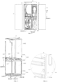
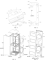
- the clothes treatment apparatus 100 includes a cabinet 10, a door assembly 15, a first clothes treatment module 20, and a second clothes treatment module 30.
- the cabinet 10 serves as a frame structure of the clothes treatment apparatus 100.
- the cabinet 10 includes a support frame 11.
- the support frame 11 includes a square base 111, a plurality of connecting transverse beams 117, a top connection frame 118, and four vertical beams, namely, a first vertical beam 115, a second vertical beam 114, a third vertical beam 112 and a fourth vertical beam 113.
- the four vertical beams extend upward from four corners of the square base 111, respectively.
- the first vertical beam 115 and the second vertical beam 114 are arranged at two rear corners of the square base 111, and the third vertical beam 112 and the fourth vertical beam 113 are arranged at two front corners of the square base 111.
- the square base 111 includes a bottom plate 1111 and four side plates 1112 arranged around sides of the chassis 32. Lower ends of two adjacent vertical beams are connected by the side plates 1112, middle portions of two adjacent vertical beams are connected by the connecting transverse beams 117, and an upper end of each vertical beam is connected to a corresponding one of four corners of the top connection frame 118.
- the top connection frame 118, the plurality of connecting transverse beams 117, and lower portions of the four vertical beams define a first accommodation space 1101 for the assembly of the first clothes treatment module 20.
- the top connection frame 118, the plurality of connecting transverse beams 117, and upper portions of the four vertical beams define a second accommodation space 1102 for the assembly of the second clothes treatment module 30.
- the first vertical beam 115 includes two short vertical beams, i.e., a first lower vertical beam 1151 extending upward from the square base 111 and a first upper vertical beam 1152 extending upward from the first lower vertical beam 1151.
- a transverse beam of the top connection frame 118 which extends in the front-rear direction and is located on a right side of the top connection frame 118, and the first upper vertical beam 1152 are integrally made by bending a same sheet.
- the first upper vertical beam 1152 is integrally formed with a portion of the top connection frame 118, so that the two do not need to be connected by any connection structure.
- a lower end of the first upper vertical beam 1152 is detachably connected to an upper end of the first lower vertical beam 1151 and is connected to the connecting transverse beam 117.
- the second vertical beam 114, the third vertical beam 112, and the fourth vertical beam 113 are all long vertical beams.
- the first lower vertical beam 1151, the second vertical beam 114, the third vertical beam 112, and the fourth vertical beam 113 are assembled by the square base 111 and the plurality of connecting transverse beams 117, so that respective upper portions of the second vertical beam 114, the third vertical beam 112 and the fourth vertical beam 113 define a large unobstructed mounting space, to facilitate the assembly of the second clothes treatment module 30.
- the first upper vertical beam 1152 attached to the top connection frame 118 is then connected with the first lower vertical beam 1151.
- the first vertical beam 115 and the second vertical beam 114 each include two short vertical beams. That is, the first vertical beam 115 includes a first lower vertical beam 1151 extending upward from the square base 111 and a first upper vertical beam 1152 extending upward from the first lower vertical beam 1151; the second vertical beam 114 includes a second lower vertical beam 1141 extending upward from the square base 111 and a second upper vertical beam 1142 extending upward from the second lower vertical beam 1141.
- a transverse beam of the top connection frame 118 which extends in the front-rear direction and is located on a right side of the top connection frame 118, and the first upper vertical beam 1152 are integrally made by bending a same sheet; and a transverse beam of the top connection frame 118, which extends in the front-rear direction and is located on a left side of the top connection frame 118, and the second upper vertical beam 1142 are integrally made by bending a same sheet.
- the first upper vertical beam 1152 is integrally formed with a portion of the top connection frame 118
- the second upper vertical beam 1142 is integrally formed with another portion of the top connection frame 118.
- the first upper vertical beam 1152 and the top connection frame 118, or the second upper vertical beam 1142 and the top connection frame 118, do not need to be connected by any connection structure.
- a lower end of the first upper vertical beam 1152 and an upper end of the first lower vertical beam 1151 are detachably connected and are connected to the connecting transverse beam 117.
- a lower end of the second upper vertical beam 1142 and an upper end of the second lower vertical beam 1141 are detachably connected and are connected to the connecting transverse beam 117.
- the third vertical beam 112 and the fourth vertical beam 113 are both long vertical beams.
- the first lower vertical beam 1151, the second lower vertical beam 1141, the third vertical beam 112, and the fourth vertical beam 113 are assembled by the square base 111 and the plurality of connecting transverse beams 117. Then, the second clothes treatment module 30 is assembled with the third vertical beam 112, the fourth vertical beam 113 and the connecting transverse beams 117. Finally, the first upper vertical beam 1152 and the second upper vertical beam 1142, which are attached to the top connection frame 118, are connected to the first lower vertical beam 1151 and the second lower vertical beam 1141, respectively.
- the second upper vertical beam 1142 and the second lower vertical beam 1141 will be exemplified below.
- the lower end of the second upper vertical beam 1142 is provided with a vertical beam connection tab 11421 extending downward.
- the vertical beam connection tab 11421 of the second upper vertical beam 1142 is first bent outward relative to the second upper vertical beam 1142 and then extends downward, so that an outer side of the upper end of the second lower vertical beam 1141 is at least partially covered by the vertical beam connection tab 11421.
- the vertical beam connection tab 11421 of the second upper vertical beam 1142 is connected to the upper end of the second lower vertical beam 1141 by fasteners, which is convenient and can ensure the reliability and stability of the connection between the second upper vertical beam 1142 and the second lower vertical beam 1141.
- the third vertical beam 112 and the fourth vertical beam 113 each have a first accommodation recess 1131 recessed inward and located in the middle of a front side surface of the third vertical beam 112 or the fourth vertical beam 113.
- a bottom wall of each first accommodation recess 1131 has a snap hole 11311, and both ends of the connecting transverse beam 117 are each provided with a tongue 1171 bent downward.
- the two ends of the connecting transverse beam 117 are arranged in the first accommodation recesses 1131 of the third vertical beam 112 and the fourth vertical beam 113, respectively, and the tongues 1171 are inserted downward into the snap holes 11311, to mount the connecting transverse beam 117 to the third vertical beam 112 and the fourth vertical beam 113.
- the fourth vertical beam 113 will be exemplified below.
- an upper end of the fourth vertical beam 113 has a first connection tab 1133 and a second connection tab 1134 arranged at 90 degrees.
- the first connection tab 1133 is provided with a notch 11331 and a first perforation 11332; and the second connection tab 1134 is provided with a second perforation 11341.
- a corner of the top connection frame 118 corresponding to the fourth vertical beam 113 is provided with a first connection flange 1182 and a second connection flange 1183 spaced apart from the first connection flange 1182.
- the first connection flange 1182 is provided with an insert 11821 bent outward and a first through-hole 11822; and the second connection flange 1183 is provided with a second through-hole 11831.
- the first connection tab 1133 is located on an outer side of the first connection flange 1182; the second connection tab 1134 is inserted through a gap between the first connection flange 1182 and the second connection flange 1183; the insert 11821 is fitted in the notch 11331; the first connection tab 1133 and the first connection flange 1182 are connected by fasteners passing through the first perforation 11332 and the first through hole 11822, and the second connection tab 1134 and the second connection flange 1183 are connected by fasteners passing through the second perforation 11341 and the second through hole 11831.
- the reliability and stability of the connection between the top connection frame 118 and the fourth vertical beam 113 can be ensured.
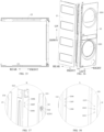
- the frame structure also includes a plurality of panels, namely a front panel 12, two side panels 13, a rear panel, and a top panel 14.
- the front panel 12 covers a front area of the support frame 11, and the front panel 12 has two openings 1201 spaced along an up-down direction. Positions of the two openings 1201 correspond to positions of clothes fetching ports 311 of the first clothes treatment module 20 and the second clothes treatment module 30.
- the rear panel covers a rear area of the support frame 11, and the two side panels 13 cover a left area and a right area of the support frame 11.
- the connection mode of the front panel 12, the side panel 13 located on the left side, and the support frame 11 will be described in detail below.
- the third vertical beam 112 is arranged at a left front corner of the square base 111.
- a front side surface of the third vertical beam 112 has a frame connection hole 1104, a frame positioning hole 1106, and a frame perforation 1105.
- a left side of the front panel 12 has a panel mounting part 121 recessed relative to an outer surface of the front panel 12.
- the panel mounting part 121 is provided with a panel connection hole 1211 corresponding to the frame connection hole 1104, a panel positioning hole 1213 corresponding to the frame positioning hole 1106, and a panel perforation 1212 corresponding to the frame perforation 1105.
- a front side of the side panel 13 located on the left side has a panel covering part 131 bent toward the front panel 12, and the panel covering part 131 has a snap groove 1311 in an inner side of the panel covering part.
- the panel mounting part 121 is connected to the third vertical beam 112 by a panel connector 122 passing through the panel connection hole 1211 and the frame connection hole 1104.
- the panel connector 122 includes a panel connection part 1221, a positioning post 1223, and a connection post 1222.
- the panel connection part 1221 is provided with a connection protrusion 1224 to define a recess 1225 recessed downward.
- the connection post 1222 includes two support legs 1221 spaced apart from each other.
- the panel mounting part 121 of the front panel 12 can be first fixed to the third vertical beam 112 by screws; then the two support legs 1221 of the panel connector 122 can be pressed so that the connection post 1222 passes through the panel connection hole 1211 and the frame connection hole 1104 sequentially; afterwards, the two support legs 1221 can be loosened to achieve an anti-disengagement effect; the positioning post 1223 is arranged to pass through the frame positioning hole 1106 and the panel positioning hole 1213; the fasteners are arranged to pass through a connection perforation 12211, the panel perforation 1212, and the frame perforation 1105, thereby further ensuring the reliability of the connection among the panel connector 122, the panel mounting part 121, and the third vertical beam 112; finally, the side panel 13 is mounted in such a way that the panel covering part 131 of the side panel 13 covers the panel mounting part 121 of the front panel 12, and the side panel 13 is pushed downward or the gravity of the side panel 13 is utilized to make an upper edge of the snap groove 1311
- a first hinge mount 1172 is arranged on a front surface of the connecting transverse beam 117 located between the third vertical beam 112 and the fourth vertical beam 113; a second hinge mount 1113 is arranged on a front surface of the side plate 1112 located between the third vertical beam 112 and the fourth vertical beam 113; and a second hinge mount 1184 is arranged on an upper surface of the top connection frame 118.
- a central portion of the front panel 12 has a mounting recess 1202, and a bottom wall of the mounting recess 1202 has a mounting hole 3325 corresponding to a perforation in the first hinge mount 1172.
- a lower portion of the front panel 12 also has one mounting recess 1202, and a bottom wall of the mounting recess 1202 has a mounting hole 3325 corresponding to a perforation in the second hinge mount 1184.
- the door assembly 15 of the clothes treatment apparatus 100 includes a first door 151 and a second door 152, the first door 151 being located below the second door 152.
- An upper end of the first door 151 and a lower end of the second door 152 are each connected to the support frame 11 by an intermediate hinge 153.
- the intermediate hinge 153 includes an intermediate mounting part 1531 and an intermediate connection part 1532.
- the intermediate mounting part 1531 is arranged in the mounting recess 1202 and connected to the first hinge mount 1172 by fasteners so as to be fixed to a front portion of the mounting support frame 11.
- the intermediate connection part 1532 is connected to the intermediate mounting part 1531.
- An upper surface of the intermediate connection part 1532 has an upper fixed shaft 1533 extending upward, and the upper fixed shaft 1533 cooperates with the second door 152; and a lower surface of the intermediate connection part 1532 has a lower fixed shaft 1534 extending downward, and the lower fixed shaft 1534 cooperates with the first door 151.
- a lower end of the first door 151 is connected to a lower end of the support frame 11 by a first end hinge 154.
- the first end hinge 154 includes a first end-face mounting part 1541 and a first end-face connection part 1542.
- the first end-face mounting part 1541 is arranged in the mounting recess 1202 and connected to the second hinge mount 1113 by fasteners so as to be fixed to a lower portion of the support frame 11.
- the first end-face connection part 1542 is connected to the first end-face mounting part 1541, and has a lower connection shaft 1543 extending upwards.
- the lower connection shaft 1543 cooperates with a lower end face of the first door 151.
- the second end hinge 155 includes a second end-face mounting part 1551 and a second end-face connection part 1552.
- the second end-face mounting part 1551 is connected to the second hinge mount 1184 on the upper surface of the top connection frame 118 by fasteners so as to be fixed to an upper portion of the support frame 11.
- the second end-face connection part 1552 is connected to the second end-face mounting part 1551, and has an upper connection shaft 1553 extending downward.
- the upper connection shaft 1553 cooperates with an upper end face of the second door 152.
- an inward side of the second door 152 is provided with a mounting port 1521, and the control panel 1523 is mounted into a mounting cavity 1520 of the second door 152 via the mounting port 1521.
- a cover plate 1522 is adapted to removably close the mounting port 1521, thereby enclosing the control panel 1523 in the mounting cavity 1520 of the second door 152.
- the first clothes treatment module 20 includes a first clothes treatment drum 21.
- the first clothes treatment module 20 may be a clothes washing module and is mounted in the first accommodation space 1101 located below.
- the second clothes treatment module 30 includes a second clothes treatment drum 31.
- the second clothes treatment module 30 may be a clothes drying module and is mounted in the second accommodation space 1102 located above.
- the clothes drying module is internally equipped with a control board that communicates with the control panel 1523. The clothes drying module works in a relatively low moisture environment, and will not cause damage to the control board.
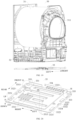
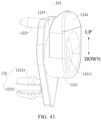
- the clothes drying module includes a clothes drying unit and a reinforcement plate 33 arranged below a chassis 32 of the clothes drying unit.
- the clothes drying module is connected to the support frame 11 through the reinforcement plate 33 pre-mounted on the clothes drying unit. There is a gap between the chassis 32 and the front panel 12.
- the chassis 32 of the clothes drying unit includes a suction zone 321 for mounting a cooling fan, a fan mounting cavity 322, and a heat pump mounting cavity 323.
- the reinforcement plate 33 has a plurality of first ventilation holes 3311 in communication with the fan mounting cavity 322, a plurality of second ventilation holes 3321, and an avoidance notch 336 corresponding to the suction zone 321.
- An outer peripheral edge of the reinforcement plate 33 is provided with a first mounting flange 334 bent upward, for connection with the connecting transverse beam 117.
- the outer peripheral edge of the reinforcement plate 33 is also provided with a second mounting flange 335 bent upward and located inside the first mounting flange 334, for connection with the chassis 32 of the clothes drying unit.
- the reinforcement plate 33 is substantially formed as a square plate and includes a first plate portion 331 and an extension portion recessed relative to the first plate portion 331.
- a plurality of second ventilation holes 3321 are provided in the extension portion.
- a plurality of reinforcement recesses 3313 are provided in the first plate portion 331 and spaced along the front-rear direction, and each reinforcement recess 3313 extends along the left-right direction.
- a plurality of reinforcement protrusions 3323 are arranged on a second plate portion 332 and spaced along a peripheral direction of the first plate portion 331.
- a fixing flange 333 bent upward is also arranged on an outer peripheral edge of the reinforcement plate 33, and is provided with a fixing hole 3331.
- the fixing flange 333 also has an insertion hole 3332 penetrating the fixing flange along its thickness direction.
- the reinforcement plate 33 is provided with a mounting boss 3324 adjacent to the insertion hole 3332, and the mounting boss 3324 is provided with a mounting hole 3325 in its top.
- the support structure 312 has an insertion part that is suitable to be inserted from the insertion hole 3332 to be connected with the mounting boss 3324.
- part of air located in the clothes washing module flows from the avoidance notch 336, through a gap between the suction zone 321 and the front panel 12, into the suction zone 321, to cool the heat pump system, and air between the clothes drying module and the clothes washing module may also circulate through the plurality of second ventilation holes 3321.
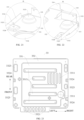
- the clothes drying unit includes a drying drum and support structures 312 arranged at front and rear ends of the drying drum.
- the support structure 312 located at the front end of the drying drum is connected to the third vertical beam 112 and the fourth vertical beam 113 by two frame connectors 313.
- the frame connector 313 includes a connection body 3134 and two connection arms 3135.
- the connection body 3134 extends along a length direction of the third vertical beam 112 or the fourth vertical beam 113.
- the two connection arms 3135 are attached to both ends of the connection body 3134 and extend toward the support structure 312, and the connection arms 3135 are recessed toward the second accommodation space 1102 relative to the connection body 3134.
- Each connection arm 3135 has a positioning recess 3137 recessed rearward in its front side, and has a pre-pressing boss 3136 protruding from its rear surface at a position corresponding to the positioning recess 3137.
- Each connection arm 3135 is provided with a first connection hole 3131 penetrating the pre-pressing boss 3136.
- the connection body 3134 is provided with a first fixing protrusion 3132 and a second fixing protrusion 3133 bent toward the third vertical beam 112 or the fourth vertical beam 113.
- the support structure 312 has a second connection hole 3121 corresponding to the first connection hole 3131, and the frame connector 313 is connected to the support structure 312 by fasteners passing through the first connection hole 3131 and the second connection hole 3121.
- the pre-pressing boss 3136 pushes the support structure 312 rearward and hence applies pre-pressure to the support structure 312, so that the support structure 312 has a backward pre-deformation, which can counteract a forward pushing force exerted by clothes in the clothes treatment drum on the support structure 312 when the clothes treatment apparatus 100 is working, and avoid problems such as air leakage or poor sealing due to the deformation of the support structure 312.
- the assembled frame connector 313 can also limit the position of the support structure 312 in the left-right direction to further improve the structural stability.
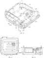
- a front side surface of each of the third vertical beam 112 and the fourth vertical beam 113 is provided with a second accommodation recess 1132 recessed inward.
- a bottom wall of the second accommodation recess 1132 on the third vertical beam 112 is provided with a first fixing perforation 11321
- a bottom wall of the second accommodation recess 1132 on the fourth vertical beam 113 is provided with a first fixing perforation 11321.
- the frame connector 313 is arranged in the second accommodation recess 1132.
- the first fixing protrusion 3132 of the frame connector 313 arranged on the third vertical beam 112 is fitted into the first fixing perforation 11321, and the second fixing protrusion 3133 thereof is fitted into the second fixing perforation 11322, so as to realize the connection between the third vertical beam 112 and the frame connector 313.
- the first fixing protrusion 3132 of the frame connector 313 arranged on the fourth vertical beam 113 is fitted into the first fixing perforation 3132, and the second fixing protrusion 3133 thereof is fitted into the second fixing perforation 11322, so as to realize the connection between the fourth vertical beam 113 and the frame connector 313.
- the positioning bracket 314 is arranged on the top of the support frame 11.
- the positioning bracket 314 includes: a first connection plate 3141 and a second connection plate 3142.
- the first connection plate 3141 extends along the horizontal direction and is fixedly connected to the support frame 11.
- the second connection plate 3142 extends in the vertical direction, an upper side of the second connection plate 3142 is connected to the first connection plate 3141, and a lower side of the second connection plate 3142 is formed into an insertion part 3143.
- the first connection plate 3141 is also provided with a positioning protrusion 3144 and a positioning flange 3145 both extending downward.
- the support frame 11 includes a top connection frame 118 on the top.
- the top connection frame 118 includes a top transverse beam 1181.
- a positioning groove 11811 and a fixing boss 11812 are arranged on a top surface of the top transverse beam 1181.
- the fixing boss 11812 is located on a side of the positioning groove 11811.
- the positioning groove 11811 and the fixing boss 11812 each extend along a length direction of the top transverse beam 1181.
- the fixing boss 11812 is provided with a bracket positioning hole 11813.
- the bracket positioning hole 11813 includes a first hole site 118131 and a second hole site 118132 in communication with each other, and a size of the first hole site 118131 is larger than a size of the second hole site 118132.
- the positioning flange 3145 When the positioning bracket 314 is mounted, the positioning flange 3145 is first inserted into the positioning groove 11811, and the positioning flange 3145 can stop against a side wall of a side of the positioning groove 11811 close to the fixing boss 11812; then, the positioning protrusion 3144 is inserted into the first hole site 118131 and slides towards the second hole site 118132; after the positioning protrusion 3144 and the bracket positioning hole 11813 are fitted in place, the positioning bracket 314 is fixedly connected to the top transverse beam 1181 by fasteners, thus making the connection between the positioning bracket 314 and the top transverse beam 1181 stable.
- the support structure 312 is provided with a first positioning plate 31221 and a second positioning plate 31222 protruding from the outer surface of the support structure 312.
- An insertion groove 3122 with a leftward opening and an insertion groove 3122 with a rightward opening are defined between the first positioning plate 31221 and the support structure 312.
- the second positioning plate 31222 closes lower openings of the insertion grooves 3122.
- a plurality of reinforcement ribs 31223 are arranged on an outer surface of the first positioning plate 31221 and spaced along the vertical direction, to improve the structural strength of the first positioning plates 31221.
- the insertion part 3143 on the lower side of the second connection plate 3142 can be inserted into the insertion groove 3122, and a bottom of the insertion groove 3122 stops against a lower edge of the second connection plate 3142, such that the insertion groove 3122 can support the second connection plate 3142 to a certain extent and improve the structural stability.
- the displacement of the support structure 312 in the front-rear direction and the left-right direction can restricted under the action of the second connection plate 3142, thereby preventing the support structure 312 from being deformed by force during the operation of the clothes treatment apparatus 100, avoiding problems such as air leakage or poor sealing due to the deformation of the support structure 312, improving the overall structural strength and extending the service life.
- references to terms “one embodiment,” “some embodiments,” “an exemplary embodiment,” “an example,” “a specific example,” “some examples” or the like means that a particular feature, structure, material, or characteristic described in connection with the embodiment or example is included in at least one embodiment or example of the present disclosure. In this specification, the above terms are not necessarily referring to the same embodiment or example. Furthermore, the particular features, structures, materials, or characteristics described may be combined in any suitable manner in one or more embodiments or examples.
Landscapes
- Engineering & Computer Science (AREA)
- Textile Engineering (AREA)
- Main Body Construction Of Washing Machines And Laundry Dryers (AREA)
- Detail Structures Of Washing Machines And Dryers (AREA)
- Holders For Apparel And Elements Relating To Apparel (AREA)
Claims (14)
- Ensemble formant bâti d'un appareil de traitement de vêtements (100), comportant :un bâti de support (11) formant un espace de réception servant à recevoir un tambour de traitement de vêtements ;une structure de support (312) raccordée au bâti de support (11) et configurée pour supporter le tambour de traitement de vêtements ;une structure de limitation agencée sur le bâti de support (11) et coopérant avec la structure de support (312) pour limiter tout déplacement de la structure de support (312) ;dans lequel la structure de limitation comporte un support de positionnement (314) agencé sur une partie supérieure du bâti de support (11) ;une rainure d'insertion (3122) est formée sur l'un parmi le support de positionnement (314) et la structure de support (312), et une partie d'insertion (3143) est formée sur l'autre parmi le support de positionnement (314) et la structure de support (312), la partie d'insertion (3143) étant insérée dans la rainure d'insertion (3122), dans lequel une direction d'extension de la partie d'insertion (3143) est perpendiculaire par rapport à la direction axiale du tambour de traitement de vêtements, dans lequel la partie d'insertion (3143) est configurée pour limiter le déplacement de la structure de support (312) dans la direction axiale du tambour de traitement de vêtements ; etcaractérisé par la structure de limitation comportant par ailleurs un connecteur de bâti (313) agencé dans la partie intermédiaire du bâti de support (11) et raccordé à la structure de support (312).
- Ensemble formant bâti selon la revendication 1, dans lequel la structure de support (312) est dotée d'une première plaque de positionnement (31221) faisant saillie depuis une surface extérieure de la structure de support (312), et la première plaque de positionnement (31221) et la structure de support (312) définissent la rainure d'insertion (3122).
- Ensemble formant bâti selon la revendication 2, dans lequel le bâti de support (11) est doté d'une deuxième plaque de positionnement (31222) faisant saillie depuis la surface extérieure de la structure de support (312), et la deuxième plaque de positionnement (31222) et la première plaque de positionnement (31221) sont raccordées pour fermer une ouverture inférieure de la rainure d'insertion (3122).
- Ensemble formant bâti selon la revendication 2, dans lequel une nervure de renfort (31223) est agencée sur une surface extérieure de la première plaque de positionnement (31221).
- Ensemble formant bâti selon la revendication 2, dans lequel au moins deux premières plaques de positionnement (31221) et la structure de support (312) définissent au moins deux rainures d'insertion (3122), et des ouvertures desdites au moins deux rainures d'insertion (3122) sont agencées à l'opposé l'une de l'autre.
- Ensemble formant bâti selon l'une quelconque des revendications 1 à 5, dans lequel le support de positionnement (314) comporte :une première plaque de raccordement (3141) raccordée de manière fixe au bâti de support (11) ; etune deuxième plaque de raccordement (3142) raccordée à la première plaque de raccordement (3141), au moins une partie de la deuxième plaque de raccordement (3142) étant formée dans la partie d'insertion (3143).
- Ensemble formant bâti selon l'une quelconque des revendications 1 à 6, dans lequel :la partie supérieure du bâti de support (11) a un trou de positionnement de support (11813), et le support de positionnement (314) a une partie saillante de positionnement (3144) faisant saillie vers le bas ;le trou de positionnement de support (11813) comporte un premier site de trou (118131) et un deuxième site de trou (118132) en communication l'un par rapport à l'autre, et une taille du premier site de trou (118131) est supérieure à une taille du deuxième site de trou (118132) ; etla partie saillante de positionnement (3144) est configurée pour être insérée vers le bas dans le premier site de trou (118131) et pour glisser vers le deuxième site de trou (118132).
- Ensemble formant bâti selon la revendication 7, dans lequel :le bâti de support (11) comporte une poutre transversale supérieure (1181), une rainure de positionnement (11811) et un bossage de fixation (11812) sont agencés sur une surface supérieure de la poutre transversale supérieure (1181), et le bossage de fixation (11812) est situé sur un côté de la rainure de positionnement (11811) ;la rainure de positionnement (11811) et le bossage de fixation (11812) s'étendent chacun le long d'une direction allant dans le sens de la longueur de la poutre transversale supérieure (1181), le trou de positionnement de support (11813) est agencé sur le bossage de fixation (11812), et le support de positionnement (314) a une bride de positionnement (3145) configurée pour être insérée dans la rainure de positionnement (11811).
- Ensemble formant bâti selon l'une quelconque des revendications 1 à 8, dans lequel le support de positionnement est raccordé de manière fixe au bâti de support par une pièce de fixation.
- Ensemble formant bâti selon l'une quelconque des revendications 1 à 9, dans lequel :le connecteur de bâti (313) a un bossage de pré-compression (3136) faisant saillie vers un côté de la structure de support (312), et le bossage de pré-compression (3136) est configuré pour exercer une pré-compression sur la structure de support (312), éventuellement,dans lequel :le connecteur de bâti (313) est doté d'un premier trou de raccordement (3131), et la structure de support (312) est dotée d'un deuxième trou de raccordement (3121) ; etle connecteur de bâti (313) et la structure de support (312) sont raccordés par une pièce de fixation qui passe au travers du premier trou de raccordement (3131) et du deuxième trou de raccordement (3121), et le premier trou de raccordement (3131) s'étend au travers du bossage de pré-compression (3136).
- Ensemble formant bâti selon la revendication 10, dans lequel le connecteur de bâti (313) comporte :un corps de raccordement (3134) raccordé de manière fixe au bâti de support (11) ; etun bras de raccordement (3135) agencé sur un côté du corps de raccordement (3134) orienté vers la structure de support (312),dans lequel un côté du bras de raccordement (3135) orienté à l'opposé de la structure de support (312) a un évidement de positionnement (3137), l'autre côté du bras de raccordement (3135) orienté vers la structure de support (312) a le bossage de pré-compression (3136), et une position du bossage de pré-compression (3136) correspond à une position de l'évidement de positionnement (3137).
- Ensemble formant bâti selon la revendication 11, dans lequel le corps de raccordement (3134) s'étend le long d'une direction verticale, deux bras de raccordement (3135) sont agencés au niveau de deux extrémités du corps de raccordement (3134) respectivement, et les bras de raccordement (3135) sont mis en retrait vers une partie intérieure du bâti de support (11) par rapport au corps de raccordement (3134).
- Ensemble formant bâti selon l'une quelconque des revendications 10 à 12, dans lequel des connecteurs de bâti (313) sont agencés des côtés gauche et droit de la structure de support (312).
- Appareil de traitement de vêtements (100), comportant l'ensemble formant bâti selon l'une quelconque des revendications 1 à 13.
Applications Claiming Priority (2)
| Application Number | Priority Date | Filing Date | Title |
|---|---|---|---|
| CN201910875832.0A CN110629484B (zh) | 2019-09-17 | 2019-09-17 | 衣物处理装置的框架组件和衣物处理装置 |
| PCT/CN2019/128388 WO2021051703A1 (fr) | 2019-09-17 | 2019-12-25 | Élément bâti destiné à un dispositif de traitement des vêtements et dispositif de traitement des vêtements |
Publications (4)
| Publication Number | Publication Date |
|---|---|
| EP3940134A1 EP3940134A1 (fr) | 2022-01-19 |
| EP3940134A4 EP3940134A4 (fr) | 2022-08-17 |
| EP3940134B1 true EP3940134B1 (fr) | 2024-03-13 |
| EP3940134C0 EP3940134C0 (fr) | 2024-03-13 |
Family
ID=68972750
Family Applications (1)
| Application Number | Title | Priority Date | Filing Date |
|---|---|---|---|
| EP19945958.7A Active EP3940134B1 (fr) | 2019-09-17 | 2019-12-25 | Élément bâti destiné à un dispositif de traitement des vêtements et dispositif de traitement des vêtements |
Country Status (5)
| Country | Link |
|---|---|
| US (1) | US20220136165A1 (fr) |
| EP (1) | EP3940134B1 (fr) |
| CN (1) | CN110629484B (fr) |
| BR (1) | BR112021019997A2 (fr) |
| WO (1) | WO2021051703A1 (fr) |
Families Citing this family (3)
| Publication number | Priority date | Publication date | Assignee | Title |
|---|---|---|---|---|
| CN114318809A (zh) * | 2020-09-30 | 2022-04-12 | 青岛海尔滚筒洗衣机有限公司 | 一种衣物处理装置的前支撑组件及衣物处理装置 |
| CN115110237A (zh) * | 2021-03-19 | 2022-09-27 | 青岛海尔滚筒洗衣机有限公司 | 叠放衣物处理设备及其连接结构 |
| KR20230172865A (ko) * | 2022-06-16 | 2023-12-26 | 엘지전자 주식회사 | 의류처리장치 |
Family Cites Families (15)
| Publication number | Priority date | Publication date | Assignee | Title |
|---|---|---|---|---|
| KR100465721B1 (ko) * | 2002-12-10 | 2005-01-13 | 엘지전자 주식회사 | 건조기의 프론트 서포터 마운팅 구조 |
| KR100610664B1 (ko) * | 2004-06-16 | 2006-08-10 | 삼성전자주식회사 | 의류건조기 |
| EP1783266B1 (fr) * | 2005-11-03 | 2017-04-19 | Electrolux Home Products Corporation N.V. | Sèche-linge |
| DE102006001437A1 (de) * | 2006-01-10 | 2007-07-12 | Miele & Cie. Kg | Gehäuse für eine frontbeschickbare Wäschebehandlungsmaschine |
| KR100732549B1 (ko) * | 2006-05-11 | 2007-06-28 | 삼성전자주식회사 | 의류건조기 |
| CN105483977B (zh) * | 2014-09-19 | 2018-01-16 | 无锡小天鹅股份有限公司 | 滚筒洗衣机组件 |
| CN204385513U (zh) * | 2014-12-03 | 2015-06-10 | 无锡小天鹅股份有限公司 | 干衣机 |
| CN206646299U (zh) * | 2017-03-02 | 2017-11-17 | 上海花猫环境科技有限公司 | 一种干衣机的内筒前支撑结构 |
| CN207391862U (zh) * | 2017-09-26 | 2018-05-22 | 青岛海尔洗衣机有限公司 | 一种干衣设备 |
| CN207537778U (zh) * | 2017-10-20 | 2018-06-26 | 青岛海尔洗衣机有限公司 | 一种衣物处理设备 |
| CN208151724U (zh) * | 2018-02-12 | 2018-11-27 | 青岛海尔滚筒洗衣机有限公司 | 一种衣物处理设备 |
| CN110219132A (zh) * | 2018-03-02 | 2019-09-10 | 青岛海尔滚筒洗衣机有限公司 | 一种双滚筒洗衣机的支撑框架和双滚筒洗衣机 |
| CN111394930A (zh) * | 2019-01-03 | 2020-07-10 | 无锡小天鹅电器有限公司 | 衣物处理装置 |
| CN209669524U (zh) * | 2019-01-03 | 2019-11-22 | 无锡小天鹅电器有限公司 | 衣物处理装置 |
| CN209669545U (zh) * | 2019-01-03 | 2019-11-22 | 无锡小天鹅电器有限公司 | 框架结构以及衣物处理装置 |
-
2019
- 2019-09-17 CN CN201910875832.0A patent/CN110629484B/zh active Active
- 2019-12-25 EP EP19945958.7A patent/EP3940134B1/fr active Active
- 2019-12-25 WO PCT/CN2019/128388 patent/WO2021051703A1/fr unknown
- 2019-12-25 BR BR112021019997A patent/BR112021019997A2/pt unknown
- 2019-12-25 US US17/434,755 patent/US20220136165A1/en active Pending
Also Published As
| Publication number | Publication date |
|---|---|
| BR112021019997A2 (pt) | 2022-04-12 |
| CN110629484A (zh) | 2019-12-31 |
| EP3940134A4 (fr) | 2022-08-17 |
| EP3940134A1 (fr) | 2022-01-19 |
| US20220136165A1 (en) | 2022-05-05 |
| EP3940134C0 (fr) | 2024-03-13 |
| WO2021051703A1 (fr) | 2021-03-25 |
| CN110629484B (zh) | 2021-09-21 |
Similar Documents
| Publication | Publication Date | Title |
|---|---|---|
| EP3940134B1 (fr) | Élément bâti destiné à un dispositif de traitement des vêtements et dispositif de traitement des vêtements | |
| JP3916599B2 (ja) | 洗濯機 | |
| CN113308842A (zh) | 堆叠式衣物处理装置 | |
| CN113308844A (zh) | 堆叠式衣物处理装置 | |
| KR20070006491A (ko) | 의류건조기 | |
| KR101467760B1 (ko) | 세탁장치 | |
| JP2021192851A (ja) | 洗濯機 | |
| CN109154466B (zh) | 铰链装置及具备该铰链装置的收纳箱 | |
| CN111394930A (zh) | 衣物处理装置 | |
| CN111455609A (zh) | 衣物处理装置 | |
| CN111394952A (zh) | 衣物处理装置 | |
| US20220081819A1 (en) | Support frame and laundry processing device | |
| CN209798343U (zh) | 衣物处理装置 | |
| CN111394929A (zh) | 衣物处理装置 | |
| CN113308843A (zh) | 堆叠式衣物处理装置 | |
| WO2020140350A1 (fr) | Structure de cadre et dispositif de traitement du linge | |
| EP3556928B1 (fr) | Dispositif de traitement de linge et boîtier associé | |
| WO2020140351A1 (fr) | Dispositif de traitement de linge | |
| JP6975801B2 (ja) | 空気調和機のケーシングアセンブリ及び空気調和機 | |
| CN111394950A (zh) | 支撑框架以及衣物处理装置 | |
| CN111394951A (zh) | 框架结构以及衣物处理装置 | |
| KR101203569B1 (ko) | 공기조화기의 실내기 | |
| CN219063735U (zh) | 用于空调器室内机的面板部件和具有其的空调器室内机 | |
| JP2019007652A (ja) | 冷却貯蔵庫 | |
| KR20030038031A (ko) | 공기조화기 |
Legal Events
| Date | Code | Title | Description |
|---|---|---|---|
| STAA | Information on the status of an ep patent application or granted ep patent |
Free format text: STATUS: THE INTERNATIONAL PUBLICATION HAS BEEN MADE |
|
| PUAI | Public reference made under article 153(3) epc to a published international application that has entered the european phase |
Free format text: ORIGINAL CODE: 0009012 |
|
| STAA | Information on the status of an ep patent application or granted ep patent |
Free format text: STATUS: REQUEST FOR EXAMINATION WAS MADE |
|
| 17P | Request for examination filed |
Effective date: 20211013 |
|
| AK | Designated contracting states |
Kind code of ref document: A1 Designated state(s): AL AT BE BG CH CY CZ DE DK EE ES FI FR GB GR HR HU IE IS IT LI LT LU LV MC MK MT NL NO PL PT RO RS SE SI SK SM TR |
|
| REG | Reference to a national code |
Ref country code: DE Ref legal event code: R079 Ref document number: 602019048462 Country of ref document: DE Free format text: PREVIOUS MAIN CLASS: D06F0058060000 Ipc: D06F0039120000 Ref country code: DE Ref legal event code: R079 Free format text: PREVIOUS MAIN CLASS: D06F0058060000 Ipc: D06F0039120000 |
|
| A4 | Supplementary search report drawn up and despatched |
Effective date: 20220714 |
|
| RIC1 | Information provided on ipc code assigned before grant |
Ipc: D06F 58/06 20060101ALN20220708BHEP Ipc: D06F 29/00 20060101ALN20220708BHEP Ipc: D06F 39/14 20060101ALN20220708BHEP Ipc: D06F 31/00 20060101ALN20220708BHEP Ipc: D06F 39/12 20060101AFI20220708BHEP |
|
| DAV | Request for validation of the european patent (deleted) | ||
| DAX | Request for extension of the european patent (deleted) | ||
| STAA | Information on the status of an ep patent application or granted ep patent |
Free format text: STATUS: EXAMINATION IS IN PROGRESS |
|
| 17Q | First examination report despatched |
Effective date: 20230206 |
|
| GRAP | Despatch of communication of intention to grant a patent |
Free format text: ORIGINAL CODE: EPIDOSNIGR1 |
|
| STAA | Information on the status of an ep patent application or granted ep patent |
Free format text: STATUS: GRANT OF PATENT IS INTENDED |
|
| INTG | Intention to grant announced |
Effective date: 20231117 |
|
| RIC1 | Information provided on ipc code assigned before grant |
Ipc: D06F 58/06 20060101ALN20231103BHEP Ipc: D06F 29/00 20060101ALN20231103BHEP Ipc: D06F 39/14 20060101ALN20231103BHEP Ipc: D06F 31/00 20060101ALN20231103BHEP Ipc: D06F 39/12 20060101AFI20231103BHEP |
|
| GRAS | Grant fee paid |
Free format text: ORIGINAL CODE: EPIDOSNIGR3 |
|
| GRAA | (expected) grant |
Free format text: ORIGINAL CODE: 0009210 |
|
| STAA | Information on the status of an ep patent application or granted ep patent |
Free format text: STATUS: THE PATENT HAS BEEN GRANTED |
|
| AK | Designated contracting states |
Kind code of ref document: B1 Designated state(s): AL AT BE BG CH CY CZ DE DK EE ES FI FR GB GR HR HU IE IS IT LI LT LU LV MC MK MT NL NO PL PT RO RS SE SI SK SM TR |
|
| REG | Reference to a national code |
Ref country code: GB Ref legal event code: FG4D |
|
| REG | Reference to a national code |
Ref country code: CH Ref legal event code: EP |
|
| REG | Reference to a national code |
Ref country code: DE Ref legal event code: R096 Ref document number: 602019048462 Country of ref document: DE |
|
| REG | Reference to a national code |
Ref country code: IE Ref legal event code: FG4D |
|
| U01 | Request for unitary effect filed |
Effective date: 20240313 |
|
| U07 | Unitary effect registered |
Designated state(s): AT BE BG DE DK EE FI FR IT LT LU LV MT NL PT SE SI Effective date: 20240320 |