EP3939816B1 - Hybridfahrzeug mit einer tankvorrichtung - Google Patents
Hybridfahrzeug mit einer tankvorrichtung Download PDFInfo
- Publication number
- EP3939816B1 EP3939816B1 EP20185666.3A EP20185666A EP3939816B1 EP 3939816 B1 EP3939816 B1 EP 3939816B1 EP 20185666 A EP20185666 A EP 20185666A EP 3939816 B1 EP3939816 B1 EP 3939816B1
- Authority
- EP
- European Patent Office
- Prior art keywords
- tank
- cooling
- hybrid vehicle
- cooling circuit
- pressure
- Prior art date
- Legal status (The legal status is an assumption and is not a legal conclusion. Google has not performed a legal analysis and makes no representation as to the accuracy of the status listed.)
- Active
Links
Images
Classifications
-
- B—PERFORMING OPERATIONS; TRANSPORTING
- B60—VEHICLES IN GENERAL
- B60K—ARRANGEMENT OR MOUNTING OF PROPULSION UNITS OR OF TRANSMISSIONS IN VEHICLES; ARRANGEMENT OR MOUNTING OF PLURAL DIVERSE PRIME-MOVERS IN VEHICLES; AUXILIARY DRIVES FOR VEHICLES; INSTRUMENTATION OR DASHBOARDS FOR VEHICLES; ARRANGEMENTS IN CONNECTION WITH COOLING, AIR INTAKE, GAS EXHAUST OR FUEL SUPPLY OF PROPULSION UNITS IN VEHICLES
- B60K15/00—Arrangement in connection with fuel supply of combustion engines or other fuel consuming energy converters, e.g. fuel cells; Mounting or construction of fuel tanks
- B60K15/03—Fuel tanks
-
- F—MECHANICAL ENGINEERING; LIGHTING; HEATING; WEAPONS; BLASTING
- F01—MACHINES OR ENGINES IN GENERAL; ENGINE PLANTS IN GENERAL; STEAM ENGINES
- F01P—COOLING OF MACHINES OR ENGINES IN GENERAL; COOLING OF INTERNAL-COMBUSTION ENGINES
- F01P3/00—Liquid cooling
- F01P3/20—Cooling circuits not specific to a single part of engine or machine
-
- B—PERFORMING OPERATIONS; TRANSPORTING
- B60—VEHICLES IN GENERAL
- B60K—ARRANGEMENT OR MOUNTING OF PROPULSION UNITS OR OF TRANSMISSIONS IN VEHICLES; ARRANGEMENT OR MOUNTING OF PLURAL DIVERSE PRIME-MOVERS IN VEHICLES; AUXILIARY DRIVES FOR VEHICLES; INSTRUMENTATION OR DASHBOARDS FOR VEHICLES; ARRANGEMENTS IN CONNECTION WITH COOLING, AIR INTAKE, GAS EXHAUST OR FUEL SUPPLY OF PROPULSION UNITS IN VEHICLES
- B60K1/00—Arrangement or mounting of electrical propulsion units
-
- B—PERFORMING OPERATIONS; TRANSPORTING
- B60—VEHICLES IN GENERAL
- B60K—ARRANGEMENT OR MOUNTING OF PROPULSION UNITS OR OF TRANSMISSIONS IN VEHICLES; ARRANGEMENT OR MOUNTING OF PLURAL DIVERSE PRIME-MOVERS IN VEHICLES; AUXILIARY DRIVES FOR VEHICLES; INSTRUMENTATION OR DASHBOARDS FOR VEHICLES; ARRANGEMENTS IN CONNECTION WITH COOLING, AIR INTAKE, GAS EXHAUST OR FUEL SUPPLY OF PROPULSION UNITS IN VEHICLES
- B60K11/00—Arrangement in connection with cooling of propulsion units
- B60K11/02—Arrangement in connection with cooling of propulsion units with liquid cooling
-
- B—PERFORMING OPERATIONS; TRANSPORTING
- B60—VEHICLES IN GENERAL
- B60K—ARRANGEMENT OR MOUNTING OF PROPULSION UNITS OR OF TRANSMISSIONS IN VEHICLES; ARRANGEMENT OR MOUNTING OF PLURAL DIVERSE PRIME-MOVERS IN VEHICLES; AUXILIARY DRIVES FOR VEHICLES; INSTRUMENTATION OR DASHBOARDS FOR VEHICLES; ARRANGEMENTS IN CONNECTION WITH COOLING, AIR INTAKE, GAS EXHAUST OR FUEL SUPPLY OF PROPULSION UNITS IN VEHICLES
- B60K6/00—Arrangement or mounting of plural diverse prime-movers for mutual or common propulsion, e.g. hybrid propulsion systems comprising electric motors and internal combustion engines
- B60K6/20—Arrangement or mounting of plural diverse prime-movers for mutual or common propulsion, e.g. hybrid propulsion systems comprising electric motors and internal combustion engines the prime-movers consisting of electric motors and internal combustion engines, e.g. HEVs
- B60K6/22—Arrangement or mounting of plural diverse prime-movers for mutual or common propulsion, e.g. hybrid propulsion systems comprising electric motors and internal combustion engines the prime-movers consisting of electric motors and internal combustion engines, e.g. HEVs characterised by apparatus, components or means specially adapted for HEVs
- B60K6/26—Arrangement or mounting of plural diverse prime-movers for mutual or common propulsion, e.g. hybrid propulsion systems comprising electric motors and internal combustion engines the prime-movers consisting of electric motors and internal combustion engines, e.g. HEVs characterised by apparatus, components or means specially adapted for HEVs characterised by the motors or the generators
-
- B—PERFORMING OPERATIONS; TRANSPORTING
- B60—VEHICLES IN GENERAL
- B60K—ARRANGEMENT OR MOUNTING OF PROPULSION UNITS OR OF TRANSMISSIONS IN VEHICLES; ARRANGEMENT OR MOUNTING OF PLURAL DIVERSE PRIME-MOVERS IN VEHICLES; AUXILIARY DRIVES FOR VEHICLES; INSTRUMENTATION OR DASHBOARDS FOR VEHICLES; ARRANGEMENTS IN CONNECTION WITH COOLING, AIR INTAKE, GAS EXHAUST OR FUEL SUPPLY OF PROPULSION UNITS IN VEHICLES
- B60K6/00—Arrangement or mounting of plural diverse prime-movers for mutual or common propulsion, e.g. hybrid propulsion systems comprising electric motors and internal combustion engines
- B60K6/20—Arrangement or mounting of plural diverse prime-movers for mutual or common propulsion, e.g. hybrid propulsion systems comprising electric motors and internal combustion engines the prime-movers consisting of electric motors and internal combustion engines, e.g. HEVs
- B60K6/22—Arrangement or mounting of plural diverse prime-movers for mutual or common propulsion, e.g. hybrid propulsion systems comprising electric motors and internal combustion engines the prime-movers consisting of electric motors and internal combustion engines, e.g. HEVs characterised by apparatus, components or means specially adapted for HEVs
- B60K6/28—Arrangement or mounting of plural diverse prime-movers for mutual or common propulsion, e.g. hybrid propulsion systems comprising electric motors and internal combustion engines the prime-movers consisting of electric motors and internal combustion engines, e.g. HEVs characterised by apparatus, components or means specially adapted for HEVs characterised by the electric energy storing means, e.g. batteries or capacitors
-
- B—PERFORMING OPERATIONS; TRANSPORTING
- B60—VEHICLES IN GENERAL
- B60L—PROPULSION OF ELECTRICALLY-PROPELLED VEHICLES; SUPPLYING ELECTRIC POWER FOR AUXILIARY EQUIPMENT OF ELECTRICALLY-PROPELLED VEHICLES; ELECTRODYNAMIC BRAKE SYSTEMS FOR VEHICLES IN GENERAL; MAGNETIC SUSPENSION OR LEVITATION FOR VEHICLES; MONITORING OPERATING VARIABLES OF ELECTRICALLY-PROPELLED VEHICLES; ELECTRIC SAFETY DEVICES FOR ELECTRICALLY-PROPELLED VEHICLES
- B60L58/00—Methods or circuit arrangements for monitoring or controlling batteries or fuel cells, specially adapted for electric vehicles
- B60L58/10—Methods or circuit arrangements for monitoring or controlling batteries or fuel cells, specially adapted for electric vehicles for monitoring or controlling batteries
- B60L58/24—Methods or circuit arrangements for monitoring or controlling batteries or fuel cells, specially adapted for electric vehicles for monitoring or controlling batteries for controlling the temperature of batteries
- B60L58/26—Methods or circuit arrangements for monitoring or controlling batteries or fuel cells, specially adapted for electric vehicles for monitoring or controlling batteries for controlling the temperature of batteries by cooling
-
- F—MECHANICAL ENGINEERING; LIGHTING; HEATING; WEAPONS; BLASTING
- F01—MACHINES OR ENGINES IN GENERAL; ENGINE PLANTS IN GENERAL; STEAM ENGINES
- F01P—COOLING OF MACHINES OR ENGINES IN GENERAL; COOLING OF INTERNAL-COMBUSTION ENGINES
- F01P7/00—Controlling of coolant flow
- F01P7/14—Controlling of coolant flow the coolant being liquid
- F01P7/16—Controlling of coolant flow the coolant being liquid by thermostatic control
- F01P7/165—Controlling of coolant flow the coolant being liquid by thermostatic control characterised by systems with two or more loops
-
- F—MECHANICAL ENGINEERING; LIGHTING; HEATING; WEAPONS; BLASTING
- F02—COMBUSTION ENGINES; HOT-GAS OR COMBUSTION-PRODUCT ENGINE PLANTS
- F02M—SUPPLYING COMBUSTION ENGINES IN GENERAL WITH COMBUSTIBLE MIXTURES OR CONSTITUENTS THEREOF
- F02M31/00—Apparatus for thermally treating combustion-air, fuel, or fuel-air mixture
- F02M31/20—Apparatus for thermally treating combustion-air, fuel, or fuel-air mixture for cooling
-
- B—PERFORMING OPERATIONS; TRANSPORTING
- B60—VEHICLES IN GENERAL
- B60K—ARRANGEMENT OR MOUNTING OF PROPULSION UNITS OR OF TRANSMISSIONS IN VEHICLES; ARRANGEMENT OR MOUNTING OF PLURAL DIVERSE PRIME-MOVERS IN VEHICLES; AUXILIARY DRIVES FOR VEHICLES; INSTRUMENTATION OR DASHBOARDS FOR VEHICLES; ARRANGEMENTS IN CONNECTION WITH COOLING, AIR INTAKE, GAS EXHAUST OR FUEL SUPPLY OF PROPULSION UNITS IN VEHICLES
- B60K1/00—Arrangement or mounting of electrical propulsion units
- B60K2001/003—Arrangement or mounting of electrical propulsion units with means for cooling the electrical propulsion units
- B60K2001/005—Arrangement or mounting of electrical propulsion units with means for cooling the electrical propulsion units the electric storage means
-
- B—PERFORMING OPERATIONS; TRANSPORTING
- B60—VEHICLES IN GENERAL
- B60K—ARRANGEMENT OR MOUNTING OF PROPULSION UNITS OR OF TRANSMISSIONS IN VEHICLES; ARRANGEMENT OR MOUNTING OF PLURAL DIVERSE PRIME-MOVERS IN VEHICLES; AUXILIARY DRIVES FOR VEHICLES; INSTRUMENTATION OR DASHBOARDS FOR VEHICLES; ARRANGEMENTS IN CONNECTION WITH COOLING, AIR INTAKE, GAS EXHAUST OR FUEL SUPPLY OF PROPULSION UNITS IN VEHICLES
- B60K15/00—Arrangement in connection with fuel supply of combustion engines or other fuel consuming energy converters, e.g. fuel cells; Mounting or construction of fuel tanks
- B60K15/03—Fuel tanks
- B60K2015/03072—Arrangements for reducing evaporation
- B60K2015/03078—Membranes, layers or the like covering the surface of the fuel
-
- B—PERFORMING OPERATIONS; TRANSPORTING
- B60—VEHICLES IN GENERAL
- B60K—ARRANGEMENT OR MOUNTING OF PROPULSION UNITS OR OF TRANSMISSIONS IN VEHICLES; ARRANGEMENT OR MOUNTING OF PLURAL DIVERSE PRIME-MOVERS IN VEHICLES; AUXILIARY DRIVES FOR VEHICLES; INSTRUMENTATION OR DASHBOARDS FOR VEHICLES; ARRANGEMENTS IN CONNECTION WITH COOLING, AIR INTAKE, GAS EXHAUST OR FUEL SUPPLY OF PROPULSION UNITS IN VEHICLES
- B60K15/00—Arrangement in connection with fuel supply of combustion engines or other fuel consuming energy converters, e.g. fuel cells; Mounting or construction of fuel tanks
- B60K15/03—Fuel tanks
- B60K2015/03171—Expansion tanks
-
- B—PERFORMING OPERATIONS; TRANSPORTING
- B60—VEHICLES IN GENERAL
- B60K—ARRANGEMENT OR MOUNTING OF PROPULSION UNITS OR OF TRANSMISSIONS IN VEHICLES; ARRANGEMENT OR MOUNTING OF PLURAL DIVERSE PRIME-MOVERS IN VEHICLES; AUXILIARY DRIVES FOR VEHICLES; INSTRUMENTATION OR DASHBOARDS FOR VEHICLES; ARRANGEMENTS IN CONNECTION WITH COOLING, AIR INTAKE, GAS EXHAUST OR FUEL SUPPLY OF PROPULSION UNITS IN VEHICLES
- B60K15/00—Arrangement in connection with fuel supply of combustion engines or other fuel consuming energy converters, e.g. fuel cells; Mounting or construction of fuel tanks
- B60K15/03—Fuel tanks
- B60K2015/03328—Arrangements or special measures related to fuel tanks or fuel handling
-
- B—PERFORMING OPERATIONS; TRANSPORTING
- B60—VEHICLES IN GENERAL
- B60K—ARRANGEMENT OR MOUNTING OF PROPULSION UNITS OR OF TRANSMISSIONS IN VEHICLES; ARRANGEMENT OR MOUNTING OF PLURAL DIVERSE PRIME-MOVERS IN VEHICLES; AUXILIARY DRIVES FOR VEHICLES; INSTRUMENTATION OR DASHBOARDS FOR VEHICLES; ARRANGEMENTS IN CONNECTION WITH COOLING, AIR INTAKE, GAS EXHAUST OR FUEL SUPPLY OF PROPULSION UNITS IN VEHICLES
- B60K15/00—Arrangement in connection with fuel supply of combustion engines or other fuel consuming energy converters, e.g. fuel cells; Mounting or construction of fuel tanks
- B60K15/03—Fuel tanks
- B60K2015/03328—Arrangements or special measures related to fuel tanks or fuel handling
- B60K2015/03414—Arrangements or special measures related to fuel tanks or fuel handling associated with the fuel tank for cooling heated fuel
-
- B—PERFORMING OPERATIONS; TRANSPORTING
- B60—VEHICLES IN GENERAL
- B60K—ARRANGEMENT OR MOUNTING OF PROPULSION UNITS OR OF TRANSMISSIONS IN VEHICLES; ARRANGEMENT OR MOUNTING OF PLURAL DIVERSE PRIME-MOVERS IN VEHICLES; AUXILIARY DRIVES FOR VEHICLES; INSTRUMENTATION OR DASHBOARDS FOR VEHICLES; ARRANGEMENTS IN CONNECTION WITH COOLING, AIR INTAKE, GAS EXHAUST OR FUEL SUPPLY OF PROPULSION UNITS IN VEHICLES
- B60K15/00—Arrangement in connection with fuel supply of combustion engines or other fuel consuming energy converters, e.g. fuel cells; Mounting or construction of fuel tanks
- B60K15/03—Fuel tanks
- B60K2015/03328—Arrangements or special measures related to fuel tanks or fuel handling
- B60K2015/03421—Arrangements or special measures related to fuel tanks or fuel handling to protect the fuel tank against heat
-
- F—MECHANICAL ENGINEERING; LIGHTING; HEATING; WEAPONS; BLASTING
- F01—MACHINES OR ENGINES IN GENERAL; ENGINE PLANTS IN GENERAL; STEAM ENGINES
- F01P—COOLING OF MACHINES OR ENGINES IN GENERAL; COOLING OF INTERNAL-COMBUSTION ENGINES
- F01P2050/00—Applications
- F01P2050/24—Hybrid vehicles
-
- F—MECHANICAL ENGINEERING; LIGHTING; HEATING; WEAPONS; BLASTING
- F01—MACHINES OR ENGINES IN GENERAL; ENGINE PLANTS IN GENERAL; STEAM ENGINES
- F01P—COOLING OF MACHINES OR ENGINES IN GENERAL; COOLING OF INTERNAL-COMBUSTION ENGINES
- F01P2060/00—Cooling circuits using auxiliaries
- F01P2060/10—Fuel manifold
Definitions
- the present invention relates to a hybrid vehicle with a tank device.
- hybrid vehicles can include an electric drive and an internal combustion engine as an additional drive.
- the energy for the electric drive can be kept ready in an energy store, ie in a battery or an accumulator.
- the fuel required for the internal combustion engine can be stored in a tank.
- a motor vehicle with a structure and a drive train, the drive train having a front axle, a rear axle, a drive unit and a transmission, the drive unit being designed as a hybrid drive with an internal combustion engine and at least one electric machine, the internal combustion engine being able to be supplied with fuel from at least one fuel tank, and the or each electric machine starting in motor operation can be supplied with electrical energy by at least one electrical energy store, the or each fuel tank and the or each electrical energy store being positioned in a common section of the body.
- the or each fuel tank and the or each electrical energy store can preferably be cooled together.
- the DE 10 2019 107041 A1 discloses a vehicle system comprising: a refrigeration circuit including a pump or a compressor; a gaseous fuel storage tank in thermal communication with the cooling circuit; and a controller including executable instructions stored in non-transitory memory to cool the gaseous fuel tank via the cooling circuit in response to filling of the gaseous fuel tank.
- a fuel tank structure comprising a fuel tank installed in an automobile and accommodating fuel; a bag-shaped member fixed to a ceiling portion of an interior of the fuel tank, a contact state of the bag-shaped member with a liquid surface of fuel accommodated in the fuel tank being maintained due to inflation and deflation of the bag-shaped member corresponding to a height of the liquid surface; a temperature sensor that measures a temperature of the fuel or the evaporated fuel detected in the fuel tank; and a cooling wind inlet portion through which, in a case where the temperature of the fuel or the evaporated fuel detected by the temperature sensor is higher than a predetermined temperature, cooling wind is introduced into an interior of the bag-shaped member.
- the hybrid vehicle includes an electric drive with an energy store for the electric drive and an internal combustion engine, the tank device including a tank for storing the fuel for the internal combustion engine, the hybrid vehicle including a cooling circuit with a circulating cooling medium, the cooling circuit being designed in this way that the energy store can be cooled by the cooling medium in the cooling circuit, the cooling circuit running through the tank, so that the fuel in the tank can be cooled by the cooling medium in the cooling circuit.
- a hybrid vehicle has a cooling circuit, with a coolant circulating in the cooling circuit.
- the energy store, i.e. the battery, of the electric drive is cooled by the cooling circuit and the coolant.
- the same cooling circuit is set up to cool the energy store of the electric drive is also used according to the invention to cool the tank for the fuel.
- the same cooling circuit therefore also runs through the tank, so that the tank can be cooled by the cooling medium. This keeps the temperature in the fuel tank and thus the pressure in the tank low. As a result, additional stiffening or reinforcements of the tank are not required, so that the tank device can be manufactured inexpensively.
- the hybrid vehicle includes a control unit, with the control unit optionally directing the cooling medium through the cooling circuit in the tank or not, so that the fuel in the tank is or is not cooled by the cooling medium in the cooling circuit.
- a valve can preferably be controlled by the control unit and in particular opened or closed or optionally partially opened in order to let the cooling medium flow through the tank or not.
- a temperature sensor and/or a pressure sensor is arranged in the tank and the control unit is set up according to the invention to conduct the cooling medium through the cooling circuit in the tank if the temperature at the temperature sensor and/or the pressure at the pressure sensor exceeds predetermined limit values in each case.
- the tank can be cooled via the cooling circuit of the energy store if required.
- the cooling medium in the cooling circuit is cooled by a refrigerant circuit of an air conditioning system.
- the refrigerant circuit includes a refrigerant compressor, it being possible for the refrigerant compressor to also be operated when the internal combustion engine is not in operation.
- a cooling coil is preferably arranged in the tank and the cooling circuit runs through the tank through the cooling coil.
- the cooling medium in the cooling circuit is preferably cooled by a refrigerant/cooling medium heat exchanger, ie a so-called “chiller”.
- the tank preferably has a pressure equalization tank. Overpressure in the tank can be absorbed by the pressure equalization tank.
- the pressure equalization tank is preferably divided by means of a membrane into a part facing the tank and a part facing away from the tank.
- the pressure compensation tank is preferably pressurized by a gas, such as nitrogen.
- the pressure on this side of the pressure equalization tank preferably corresponds at least to the hydrostatic pressure in the filling pipe, i.e. the result of the formula ⁇ *g*h, where h is the height of the filling pipe, g is the gravitational acceleration of approx. 9.81 m/s 2 and ⁇ is the density of the medium. With a filler pipe height of 0.7 m and a density of the petrol medium of 775 kg/m3, this results in a pressure of at least 53.2 mbar, for example.
- the tank preferably has insulation as a casing in order to prevent the tank contents from being heated by ambient heat.
- the energy store is preferably cooled to a temperature of approximately 15 to 35 degrees Celsius by the cooling circuit.
- the tank is preferably arranged in the cooling circuit before or after the refrigerant/cooling medium heat exchanger.
- the tank is preferably connected to the atmosphere via a valve, in particular a low-pressure valve, with the valve preferably being arranged before or after an activated carbon filter.
- the valve is preferably closed when the hybrid vehicle is operated purely electrically.
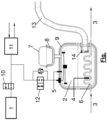
- Essential parts of a hybrid vehicle according to the invention are shown schematically in the figure.
- the hybrid vehicle includes an internal combustion engine 1 that can be supplied with fuel via a tank 2 .
- the internal combustion engine 1 is connected to an activated charcoal filter 11 via a scavenging valve 10 . Furthermore, a low-pressure valve 12 is arranged between the activated carbon filter 11 and the tank 2 .
- a cooling spiral 6 is arranged in the tank 2, so that the cooling medium of a cooling circuit 3, shown schematically as arrows in the figure, for cooling the energy store of the electric drive, also runs through the cooling spiral 6 and thus through the tank 2, around the tank 2 to cool.
- a cooling circuit 3 shown schematically as arrows in the figure, for cooling the energy store of the electric drive
- the tank 2 is filled via a filling pipe 13, at the lower end of which an inlet non-return valve 14 is arranged.
- the hybrid vehicle includes a control unit, not shown in FIG.
- the control unit activates a suitable shut-off valve.
- a temperature sensor 4 and a pressure sensor 5 are arranged in the tank 2 .
- the control unit is set up to conduct the cooling medium through the cooling coil 6 in the tank 2 when the temperature at the temperature sensor 4 and/or the pressure at the pressure sensor 5 exceeds predetermined limit values in each case.
- the cooling medium in the cooling circuit 3 can be cooled by a refrigerant circuit of an air conditioning system, in particular by a refrigerant-coolant heat exchanger, ie a so-called "chiller".
- the tank 2 has a pressure equalizing tank 7 which is divided horizontally by a membrane 8, in particular by a bag membrane, into a part facing the tank 2 and a part facing away from the tank 2.
- a membrane 8 in particular by a bag membrane
- N2 nitrogen, in the pressure equalization tank 7, at a pressure of for example at least 40 mbar - depending on the height of the filler pipe 13.
- the tank 2 has an insulation 9 as a casing in order to prevent the tank contents from being heated by ambient heat.
Landscapes
- Engineering & Computer Science (AREA)
- Mechanical Engineering (AREA)
- Chemical & Material Sciences (AREA)
- Combustion & Propulsion (AREA)
- Transportation (AREA)
- General Engineering & Computer Science (AREA)
- Life Sciences & Earth Sciences (AREA)
- Sustainable Development (AREA)
- Sustainable Energy (AREA)
- Power Engineering (AREA)
- Cooling, Air Intake And Gas Exhaust, And Fuel Tank Arrangements In Propulsion Units (AREA)
- Electric Propulsion And Braking For Vehicles (AREA)
Description
- Die vorliegende Erfindung betrifft ein Hybridfahrzeug mit einer Tankvorrichtung.
- Es ist bekannt, dass Hybridfahrzeuge einen elektrischen Antrieb und einen Verbrennungsmotor als zusätzlichen Antrieb umfassen können. Die Energie für den elektrischen Antrieb kann in einem Energiespeicher, also in einer Batterie beziehungsweise einem Akkumulator, bereitgehalten werden. Der für den Verbrennungsmotor erforderliche Kraftstoff kann in einem Tank gespeichert sein.
- Insbesondere bei Hybridfahrzeugen die auch rein elektrisch betrieben werden können, besteht das Problem, dass unter Umständen der Verbrennungsmotor und daher der Tank des Hybridfahrzeuges längere Zeit lang nicht benutzt wird. Ein Kraftstoff im Tank kann auch wenn dieser nicht benutzt wird, weiterhin ausgasen und somit den Druck im Tank erhöhen. Insbesondere wenn eine Entlüftung eines solchen nicht benutzter Tanks nicht möglich ist, kann sich in einem solchen Tank ein hoher Druck aufbauen, beispielsweise von über 300 mbar. Der Tank muss dann mit geeigneten Maßnahmen, wie Verstärkungen, entsprechend druckstabil ausgebildet werden.
- Aus der
DE 10 2010 009875 A1 ist ein Kraftfahrzeug bekannt, mit einem Aufbau und einem Antriebsstrang, wobei der Antriebsstrang eine Vorderachse, eine Hinterachse, ein Antriebsaggregat und ein Getriebe umfasst, wobei das Antriebsaggregat als Hybridantrieb mit einer Brennkraftmaschine und mindestens einer elektrischen Maschine ausgebildet ist, wobei die Brennkraftmaschine ausgehend von mindestens einem Kraftstoffstank mit Kraftstoff versorgbar ist, und wobei die oder jede elektrische Maschine im motorischen Betrieb ausgehend von mindestens einem elektrischen Energiespeicher mit elektrischer Energie versorgbar ist, wobei der oder jeder Kraftstoffstank und der oder jeder elektrische Energiespeicher in einem gemeinsamen Abschnitt des Aufbaus positioniert sind. Vorzugsweise sind der oder jeder Kraftstofftank und der oder jeder elektrische Energiespeicher gemeinsam kühlbar. - Die
DE 10 2019 107041 A1 offenbart ein Fahrzeugsystem, folgendes umfassend: einen Kühlkreislauf, der eine Pumpe oder einen Verdichter beinhaltet; einen Speichertank für gasförmigen Kraftstoff, der in Wärmekommunikation mit dem Kühlkreislauf steht; und eine Steuerung, die in einem nichtflüchtigen Speicher gespeicherte ausführbare Anweisungen beinhaltet, um den Tank für gasförmigen Kraftstoff über den Kühlkreislauf als Reaktion auf Abfüllen des Tanks für gasförmigen Kraftstoff zu kühlen. - Aus der
DE 10 2016 104820 A1 ist eine Kraftstofftankstruktur bekannt, aufweisend einen Kraftstofftank, der in einem Automobil installiert ist, und der Kraftstoff aufnimmt; ein beutelförmiges Element, das an einem Deckenabschnitt eines Innenraums des Kraftstofftanks befestigt ist, wobei ein Kontaktzustand des beutelförmigen Elements mit einer Flüssigkeitsoberfläche des in dem Kraftstofftank aufgenommenen Kraftstoffs aufgrund eines Aufblasens und Entleerens des beutelförmigen Elements entsprechend einer Höhe der Flüssigkeitsoberfläche beibehalten wird; einen Temperatursensor, der eine Temperatur des Kraftstoffs oder des verdunsteten Kraftstoffs in dem Kraftstofftank erfasst; und einen Kühlwindeinlassabschnitt, über den in einem Fall, in dem die von dem Temperatursensor erfasste Temperatur des Kraftstoffs oder des verdunsteten Kraftstoffs höher ist als eine vorbestimmte Temperatur, Kühlwind in ein Inneres des beutelförmigen Elements eingeführt wird. - Es ist eine Aufgabe der Erfindung, ein Hybridfahrzeug mit einer Tankvorrichtung anzugeben, wobei das Hybridfahrzeug auch rein elektrisch betrieben werden kann und der Tank kostengünstig gegen Beschädigungen durch Überdruck geschützt ist.
- Die Lösung der Aufgabe erfolgt durch ein Hybridfahrzeug mit einer Tankvorrichtung mit den Merkmalen gemäß Anspruch 1.
- Dabei umfasst das Hybridfahrzeug einen elektrischen Antrieb mit einem Energiespeicher für den elektrischen Antrieb, sowie einen Verbrennungsmotor, wobei die Tankvorrichtung einen Tank zur Speicherung des Kraftstoffs für den Verbrennungsmotor umfasst, wobei das Hybridfahrzeug einen Kühlkreislauf mit einem zirkulierenden Kühlmedium umfasst, wobei der Kühlkreislauf so ausgebildet ist, dass der Energiespeicher durch das Kühlmedium im Kühlkreislauf gekühlt werden kann, wobei der Kühlkreislauf durch den Tank verläuft, so dass der Kraftstoff im Tank durch das Kühlmedium im Kühlkreislauf gekühlt werden kann.
- Erfindungsgemäß verfügt ein Hybridfahrzeug über einen Kühlkreislauf, wobei in dem Kühlkreislauf ein Kühlmittel zirkuliert. Durch den Kühlkreislauf und durch das Kühlmittel wird der Energiespeicher, also die Batterie, des elektrischen Antriebs gekühlt. Der selbe Kühlkreislauf der zur Kühlung des Energiespeichers des elektrischen Antriebs eingerichtet ist, wird erfindungsgemäß auch zur Kühlung des Tanks für den Kraftstoff verwendet. Der selbe Kühlkreislauf verläuft daher auch durch den Tank, so dass der Tank durch das Kühlmedium gekühlt werden kann. Die Temperatur im Kraftstoff-Tank und hierdurch der Druck im Tank wird hierdurch gering gehalten. Zusätzliche Versteifungen oder Verstärkungen des Tanks sind hierdurch nicht erforderlich, so dass die Tankvorrichtung kostengünstig gefertigt werden kann.
- Erfindungsgemäß umfasst das Hybridfahrzeug eine Steuereinheit, wobei durch die Steuereinheit wahlweise das Kühlmedium durch den Kühlkreislauf im Tank geleitet wird oder nicht, so dass der Kraftstoff im Tank durch das Kühlmedium im Kühlkreislauf gekühlt wird oder nicht. Hierzu kann bevorzugt durch die Steuereinheit ein Ventil angesteuert werden und insbesondere geöffnet oder geschlossen oder optional teilweise geöffnet werden, um das Kühlmedium durch den Tank fließen zu lassen oder nicht.
- Im Tank ist erfindungsgemäß ein Temperatursensor und/oder ein Drucksensor angeordnet und die Steuereinheit ist erfindungsgemäß dazu eingerichtet, das Kühlmedium durch den Kühlkreislauf im Tank zu leiten, wenn die Temperatur am Temperatursensor und/oder der Druck am Drucksensor jeweils vorgegebene Grenzwerte überschreiten. Hierdurch kann der Tank über den Kühlkreislauf des Energiespeichers bei Bedarf gekühlt werden.
- Erfindungsgemäß wird das Kühlmedium im Kühlkreislauf durch einen Kältemittelkreislauf einer Klimaanlage gekühlt. Der Kältemittelkreislauf umfasst einen Kältemittelkompressor, wobei der Kältemittelkompressor auch betrieben werden kann, wenn der Verbrennungsmotor nicht in Betrieb ist.
- Weiterbildungen der Erfindung sind in den abhängigen Ansprüchen, der Beschreibung sowie den beigefügten Zeichnungen angegeben.
- Bevorzugt ist im Tank eine Kühlspirale angeordnet und der Kühlkreislauf verläuft durch die Kühlspirale durch den Tank.
- Bevorzugt wird das Kühlmedium im Kühlkreislauf durch einen Kältemittel-Kühlmedium-Wärmeübertrager, also einen sogenannten "Chiller", gekühlt.
- Bevorzugt weist der Tank einen Druckausgleichsbehälter auf. Durch den Druckausgleichsbehälter kann ein Überdruck im Tank aufgenommen werden.
- Der Druckausgleichsbehälter ist vorzugsweise mittels einer Membran in einen dem Tank zugewandten Teil und einen vom Tank abgewandten Teil abgeteilt. Auf der dem Tank abgewandten Seite der Membran ist der Druckausgleichsbehälter bevorzugt durch ein Gas, wie Stickstoff, mit Druck beaufschlagt. Der Druck auf dieser Seite des Druckausgleichsbehälters entspricht bevorzugt mindestens dem hydrostatischen Druck im Einfüllrohr, also dem Ergebnis der Formel ρ*g*h, wobei h die Höhe des Einfüllrohres ist, g die Schwerebeschleunigung ca. 9,81 m/s2 und ρ die Dichte des Mediums. Bei einer Höhe des Einfüllrohres von 0,7 m und einer Dichte des Mediums Benzin von 775 kg/m3 ergibt dies beispielsweise einen Druck von mindestens 53,2 mbar.
- Vorzugsweise weist der Tank eine Isolierung als Ummantelung auf, um eine Erwärmung des Tankinhalts durch Umgebungswärme zu verhindern. Bevorzugt wird der Energiespeicher durch den Kühlkreislauf auf eine Temperatur von etwa 15 bis 35 Grad Celsius gekühlt.
- Der Tank ist bevorzugt im Kühlkreislauf vor oder nach dem Kältemittel-Kühlmedium-Wärmeübertrager angeordnet.
- Der Tank ist vorzugsweise über ein Ventil, insbesondere ein Niederdruckventil, mit der Atmosphäre verbunden, wobei das Ventil bevorzugt vor oder nach einem Aktivkohlefilter angeordnet ist. Das Ventil ist bevorzugt bei einem rein elektrischen Betrieb des Hybridfahrzeugs geschlossen.
- Die Erfindung wird im Folgenden beispielhaft unter Bezugnahme auf die Zeichnung beschrieben.
- Fig.
- ist eine schematische Schnittansicht einer Tankvorrichtung eines erfindungsgemäßen Hybridfahrzeugs.
- In der Fig. sind wesentliche Teile eines erfindungsgemäßen Hybridfahrzeugs, wie insbesondere dessen Tankvorrichtung, schematisch dargestellt.
- Das Hybridfahrzeug umfasst einen Verbrennungsmotor 1, der über einen Tank 2 mit Kraftstoff versorgt werden kann. Der Verbrennungsmotor 1 ist über ein Spülventil 10 mit einem Aktivkohlefilter 11 verbunden. Zwischen dem Aktivkohlefilter 11 und dem Tank 2 ist ferner ein Niederdruckventil 12 angeordnet.
- Im Tank 2 ist eine Kühlspirale 6 angeordnet, so dass das Kühlmedium eines in der Fig. schematisch als Pfeile dargestellten Kühlkreislaufs 3, zur Kühlung des Energiespeichers des elektrischen Antriebs, auch durch die Kühlspirale 6 und somit durch den Tank 2 verläuft, um den Tank 2 zu kühlen.
- Der Tank 2 wird über ein Einfüllrohr 13 befüllt, an dessen unterem Ende ein Einlassrückschlagventil 14 angeordnet ist.
- Das Hybridfahrzeug umfasst eine in Fig. nicht dargestellte Steuereinheit, wobei durch die Steuereinheit wahlweise das Kühlmedium durch die Kühlspirale 6 im Tank 2 geleitet wird oder nicht, so dass der Kraftstoff im Tank 2 durch das Kühlmedium im Kühlkreislauf 3 gekühlt wird oder nicht. Die Steuereinheit steuert dazu ein geeignetes Absperrventil an.
- Im Tank 2 ist ein Temperatursensor 4 und ein Drucksensor 5 angeordnet. Die Steuereinheit ist dazu eingerichtet, das Kühlmedium durch die Kühlspirale 6 im Tank 2 zu leiten, wenn die Temperatur am Temperatursensor 4 und/oder der Druck am Drucksensor 5 jeweils vorgegebene Grenzwerte überschreiten.
- Das Kühlmedium im Kühlkreislauf 3 kann durch einen Kältemittelkreislauf einer Klimaanlage gekühlt werden, insbesondere durch einen Kältemittel-Kühlmedium-Wärmeübertrager, also einen sogenannten "Chiller".
- Der Tank 2 weist einen Druckausgleichsbehälter 7 auf, der durch eine Membran 8, insbesondere durch eine Sackmembran, in einen dem Tank 2 zugewandten Teil und einen vom Tank 2 abgewandten Teil horizontal abgeteilt ist. Auf der dem Tank 2 abgewandten Seite der Membran 8 befindet sich Stickstoff, N2, im Druckausgleichsbehälter 7, mit einem Druck von beispielsweise mindestens 40 mbar - abhängig von der Höhe des Einfüllrohrs 13.
- Ferner weist der Tank 2 eine Isolierung 9 als Ummantelung auf, um eine Erwärmung des Tankinhalts durch Umgebungswärme zu verhindern.
- Durch diese Maßnahmen ist der Tank vor der Entstehung eines Überdrucks durch das Ausgasen des Kraftstoffs geschützt. Teure Verstärkungsmaßnahmen des Tanks sind daher nicht erforderlich.
-
- 1
- Verbrennungsmotor
- 2
- Tank
- 3
- Kühlkreislauf
- 4
- Temperatursensor
- 5
- Drucksensor
- 6
- Kühlspirale
- 7
- Druckausgleichsbehälter
- 8
- Membran
- 9
- Isolierung
- 10
- Spülventil
- 11
- Aktivkohlefilter
- 12
- Niederdruckventil
- 13
- Einfüllrohr
- 14
- Einlassrückschlagventil
Claims (6)
- Hybridfahrzeug mit einer Tankvorrichtung, wobei das Hybridfahrzeug einen elektrischen Antrieb mit einem Energiespeicher für den elektrischen Antrieb umfasst, sowie einen Verbrennungsmotor (1), wobei die Tankvorrichtung einen Tank (2) zur Speicherung des Kraftstoffs für den Verbrennungsmotor (1) umfasst, wobei das Hybridfahrzeug einen Kühlkreislauf (3) mit einem zirkulierenden Kühlmedium umfasst, wobei der Kühlkreislauf (3) so ausgebildet ist, dass der Energiespeicher durch das Kühlmedium im Kühlkreislauf (3) gekühlt werden kann,
wobei der Kühlkreislauf (3) durch den Tank (2) verläuft, so dass der Kraftstoff im Tank (2) durch das Kühlmedium im Kühlkreislauf gekühlt werden kann, dadurch gekennzeich - net, dass das Hybridfahrzeug eine Steuereinheit umfasst, wobei durch die Steuereinheit wahlweise das Kühlmedium durch den Kühlkreislauf (3) im Tank (2) geleitet wird oder nicht, so dass der Kraftstoff im Tank (2) durch das Kühlmedium im Kühlkreislauf (3) gekühlt wird oder nicht, wobei im Tank (2) ein Temperatursensor (4) und/oder ein Drucksensor (5) angeordnet ist und die Steuereinheit dazu eingerichtet ist, das Kühlmedium durch den Kühlkreislauf (3) im Tank (2) zu leiten, wenn die Temperatur am Temperatursensor (4) und/oder der Druck am Drucksensor (5) jeweils vorgegebene Grenzwerte überschreiten, wobei das Kühlmedium im Kühlkreislauf (3) durch einen Kältemittelkreislauf einer Klimaanlage gekühlt wird, wobei der Kältemittelkreislauf einen Kältemittelkompressor umfasst, wobei der Kältemittelkompressor auch betrieben werden kann, wenn der Verbrennungsmotor (1) nicht in Betrieb ist. - Hybridfahrzeug nach Anspruch 1,
dadurch gekennzeichnet , dass das Kühlmedium im Kühlkreislauf (3) durch einen Kältemittelkreislauf einer Klimaanlage gekühlt wird, nämlich durch einen Kältemittel-Kühlmedium-Wärmeübertrager. - Hybridfahrzeug nach zumindest einem der vorhergehenden Ansprüche,
dadurch gekennzeichnet , dass im Tank (2) eine Kühlspirale (6) angeordnet ist und der Kühlkreislauf (3) durch die Kühlspirale (6) durch den Tank (2) verläuft. - Hybridfahrzeug nach zumindest einem der vorhergehenden Ansprüche,
dadurch gekennzeichnet , dass der Tank (2) einen Druckausgleichsbehälter (7) aufweist. - Hybridfahrzeug nach Anspruch 4,
dadurch gekennzeichnet , dass der Druckausgleichsbehälter (7) mittels einer Membran (8) in einen dem Tank (2) zugewandten Teil und einen vom Tank (2) abgewandten Teil abgeteilt ist, wobei der Druckausgleichsbehälter (7) auf der dem Tank (2) abgewandten Seite der Membran (8) durch ein Gas mit Druck beaufschlagt ist, insbesondere mit einem Druck der mindestens dem hydrostatischen Druck in einem Einfüllrohr (13) des Tanks (2) entspricht. - Hybridfahrzeug nach zumindest einem der vorhergehenden Ansprüche,
dadurch gekennzeichnet , dass der Tank (2) eine Isolierung (9) als Ummantelung aufweist, um eine Erwärmung des Tankinhalts durch Umgebungswärme zu verhindern.
Priority Applications (3)
| Application Number | Priority Date | Filing Date | Title |
|---|---|---|---|
| EP20185666.3A EP3939816B1 (de) | 2020-07-14 | 2020-07-14 | Hybridfahrzeug mit einer tankvorrichtung |
| US17/366,598 US11352938B2 (en) | 2020-07-14 | 2021-07-02 | Hybrid vehicle with a refueling device |
| CN202110783154.2A CN113928111A (zh) | 2020-07-14 | 2021-07-12 | 具有加油装置的混合动力车辆 |
Applications Claiming Priority (1)
| Application Number | Priority Date | Filing Date | Title |
|---|---|---|---|
| EP20185666.3A EP3939816B1 (de) | 2020-07-14 | 2020-07-14 | Hybridfahrzeug mit einer tankvorrichtung |
Publications (2)
| Publication Number | Publication Date |
|---|---|
| EP3939816A1 EP3939816A1 (de) | 2022-01-19 |
| EP3939816B1 true EP3939816B1 (de) | 2023-05-03 |
Family
ID=71614743
Family Applications (1)
| Application Number | Title | Priority Date | Filing Date |
|---|---|---|---|
| EP20185666.3A Active EP3939816B1 (de) | 2020-07-14 | 2020-07-14 | Hybridfahrzeug mit einer tankvorrichtung |
Country Status (3)
| Country | Link |
|---|---|
| US (1) | US11352938B2 (de) |
| EP (1) | EP3939816B1 (de) |
| CN (1) | CN113928111A (de) |
Families Citing this family (1)
| Publication number | Priority date | Publication date | Assignee | Title |
|---|---|---|---|---|
| CN116424088B (zh) * | 2023-04-03 | 2025-09-19 | 一汽解放汽车有限公司 | 油箱散热系统和车辆 |
Family Cites Families (12)
| Publication number | Priority date | Publication date | Assignee | Title |
|---|---|---|---|---|
| US5263462A (en) * | 1992-10-29 | 1993-11-23 | General Motors Corporation | System and method for detecting leaks in a vapor handling system |
| DE202008000314U1 (de) * | 2008-01-08 | 2008-03-20 | Gämlich, Eckhard | Ausdehnungsgefäß für Warmwasserheizungen |
| DE102010009875A1 (de) * | 2010-02-23 | 2011-08-25 | Dr. Ing. h.c. F. Porsche Aktiengesellschaft, 70435 | Kraftfahrzeug |
| DE102015006812A1 (de) * | 2015-05-26 | 2016-12-01 | Linde Aktiengesellschaft | Vorrichtung und Verfahren zum Druckausgleich |
| JP2017001571A (ja) * | 2015-06-12 | 2017-01-05 | トヨタ自動車株式会社 | 燃料タンク構造 |
| CN106240348A (zh) * | 2016-08-02 | 2016-12-21 | 观致汽车有限公司 | 控制燃料箱内气压的系统及方法 |
| CN107117019B (zh) * | 2017-04-21 | 2023-05-23 | 内蒙古科技大学 | 一种无碳罐式车载油箱油气回收装置 |
| DE102017118951B4 (de) * | 2017-08-18 | 2019-11-14 | Arianegroup Gmbh | Kühlung einer Abdampfung von Flüssiggas zum Antrieb von Maschinen, Anlagen oder Fahrzeugen |
| DE102017011169A1 (de) * | 2017-12-04 | 2018-05-30 | Daimler Ag | Fahrzeug |
| DE102018201112B3 (de) * | 2018-01-24 | 2019-01-24 | Ford Global Technologies, Llc | Baugruppe für ein Hybridelektrofahrzeug und Hybridelektrofahrzeug |
| US11041424B2 (en) * | 2018-03-21 | 2021-06-22 | Ford Global Technologies, Llc | Method and system for operating a gaseous fuel vehicle |
| CN210283885U (zh) * | 2019-07-09 | 2020-04-10 | 江苏凌动新能源车业有限公司 | 一种耐高温的塑料油箱 |
-
2020
- 2020-07-14 EP EP20185666.3A patent/EP3939816B1/de active Active
-
2021
- 2021-07-02 US US17/366,598 patent/US11352938B2/en active Active
- 2021-07-12 CN CN202110783154.2A patent/CN113928111A/zh active Pending
Also Published As
| Publication number | Publication date |
|---|---|
| EP3939816A1 (de) | 2022-01-19 |
| US11352938B2 (en) | 2022-06-07 |
| CN113928111A (zh) | 2022-01-14 |
| US20220018277A1 (en) | 2022-01-20 |
Similar Documents
| Publication | Publication Date | Title |
|---|---|---|
| DE112010003103T5 (de) | Gasfüllsystem und Gasfüllvorrichtung | |
| WO2008055731A1 (de) | Fluidspeicher mit thermomanagement | |
| DE102019125184A1 (de) | Druckbehälter sowie Kraftfahrzeug | |
| DE112009005107T5 (de) | Gasabfüllsystem | |
| DE10202807A1 (de) | System zur Temperierung von Hochleistungs-Sekundärbatterien für Fahrzeuganwendungen | |
| DE102009039645A1 (de) | Befüllen von Speicherbehältern mit verdichteten Medien | |
| EP3939816B1 (de) | Hybridfahrzeug mit einer tankvorrichtung | |
| EP2888783B1 (de) | Kraftfahrzeug mit batteriekühlung | |
| DE102011012723A1 (de) | Kühlsystem für eine mobile Arbeitsmaschine | |
| WO2021052994A2 (de) | Druckbehälter sowie kraftfahrzeug | |
| DE102017004448A1 (de) | Verfahren zum Betreiben eines Brennstoffzellensystems | |
| DE102013001676A1 (de) | Verfahren und Betankungseinrichtung zum Betanken eines Speicherbehälters mit einem unter Druck stehenden, gasförmigen Medium | |
| WO2018210526A2 (de) | Schienenfahrzeug | |
| DE102010033188A1 (de) | Kühlvorrichtung für einen elektrischen Energiespeicher | |
| DE102021209366A1 (de) | Druckbehältersystem | |
| DE4242644C2 (de) | Verfahren zum Betreiben eines Wasserstoffmotors, Kraftfahrzeugantrieb | |
| DE102012211827A1 (de) | Batteriegehäuse, Batterie, Verfahren zur Wartung und/oder Reparatur einer Batterie sowie Kraftfahrzeug | |
| DE102020201046A1 (de) | Druckgasspeicheraufnahmevorrichtung für ein Kraftfahrzeug, System mit einem Kraftfahrzeug und einer Kühlungsvorrichtung, Tankstelle für ein solches System sowie Verfahren zum Betanken eines Kraftfahrzeuges | |
| DE102020106950A1 (de) | Ladesäule für mindestens teilweise elektrisch betreibbares Fahrzeug | |
| DE102015206782A1 (de) | Verfahren zum Betanken eines kryogenen Druckbehälters eines Kraftfahrzeuges | |
| EP2199138A2 (de) | Verfahren zur Betriebsentlüftungssteuerung an einem Kunststoff-Kraftstoffbehälter sowie Kunststoff-Kraftstoffbehälter | |
| DE102013021530A1 (de) | Batterie und Verfahren zum Betrieb der Batterie | |
| DE102020104891A1 (de) | Kühleinrichtung zum Kühlen eines Energiespeichers eines Kraftfahrzeugs sowie Kraftfahrzeug | |
| DE102011014237A1 (de) | Kraftfahrzeugvorrichtung mit einer Kraftstoffvorrichtung | |
| DE102018132035A1 (de) | Batterie für ein Kraftfahrzeug, Kraftfahrzeug und Verfahren zum Betreiben einer Batterie |
Legal Events
| Date | Code | Title | Description |
|---|---|---|---|
| PUAI | Public reference made under article 153(3) epc to a published international application that has entered the european phase |
Free format text: ORIGINAL CODE: 0009012 |
|
| STAA | Information on the status of an ep patent application or granted ep patent |
Free format text: STATUS: THE APPLICATION HAS BEEN PUBLISHED |
|
| AK | Designated contracting states |
Kind code of ref document: A1 Designated state(s): AL AT BE BG CH CY CZ DE DK EE ES FI FR GB GR HR HU IE IS IT LI LT LU LV MC MK MT NL NO PL PT RO RS SE SI SK SM TR |
|
| STAA | Information on the status of an ep patent application or granted ep patent |
Free format text: STATUS: REQUEST FOR EXAMINATION WAS MADE |
|
| 17P | Request for examination filed |
Effective date: 20220607 |
|
| RBV | Designated contracting states (corrected) |
Designated state(s): AL AT BE BG CH CY CZ DE DK EE ES FI FR GB GR HR HU IE IS IT LI LT LU LV MC MK MT NL NO PL PT RO RS SE SI SK SM TR |
|
| GRAP | Despatch of communication of intention to grant a patent |
Free format text: ORIGINAL CODE: EPIDOSNIGR1 |
|
| RIC1 | Information provided on ipc code assigned before grant |
Ipc: B60K 15/03 20060101ALI20221215BHEP Ipc: B60K 1/00 20060101AFI20221215BHEP |
|
| STAA | Information on the status of an ep patent application or granted ep patent |
Free format text: STATUS: GRANT OF PATENT IS INTENDED |
|
| INTG | Intention to grant announced |
Effective date: 20230119 |
|
| GRAS | Grant fee paid |
Free format text: ORIGINAL CODE: EPIDOSNIGR3 |
|
| GRAA | (expected) grant |
Free format text: ORIGINAL CODE: 0009210 |
|
| STAA | Information on the status of an ep patent application or granted ep patent |
Free format text: STATUS: THE PATENT HAS BEEN GRANTED |
|
| AK | Designated contracting states |
Kind code of ref document: B1 Designated state(s): AL AT BE BG CH CY CZ DE DK EE ES FI FR GB GR HR HU IE IS IT LI LT LU LV MC MK MT NL NO PL PT RO RS SE SI SK SM TR |
|
| REG | Reference to a national code |
Ref country code: GB Ref legal event code: FG4D Free format text: NOT ENGLISH |
|
| REG | Reference to a national code |
Ref country code: DE Ref legal event code: R096 Ref document number: 502020003148 Country of ref document: DE |
|
| REG | Reference to a national code |
Ref country code: AT Ref legal event code: REF Ref document number: 1564300 Country of ref document: AT Kind code of ref document: T Effective date: 20230515 Ref country code: CH Ref legal event code: EP |
|
| REG | Reference to a national code |
Ref country code: IE Ref legal event code: FG4D Free format text: LANGUAGE OF EP DOCUMENT: GERMAN |
|
| REG | Reference to a national code |
Ref country code: LT Ref legal event code: MG9D |
|
| REG | Reference to a national code |
Ref country code: NL Ref legal event code: MP Effective date: 20230503 |
|
| PG25 | Lapsed in a contracting state [announced via postgrant information from national office to epo] |
Ref country code: SE Free format text: LAPSE BECAUSE OF FAILURE TO SUBMIT A TRANSLATION OF THE DESCRIPTION OR TO PAY THE FEE WITHIN THE PRESCRIBED TIME-LIMIT Effective date: 20230503 Ref country code: PT Free format text: LAPSE BECAUSE OF FAILURE TO SUBMIT A TRANSLATION OF THE DESCRIPTION OR TO PAY THE FEE WITHIN THE PRESCRIBED TIME-LIMIT Effective date: 20230904 Ref country code: NO Free format text: LAPSE BECAUSE OF FAILURE TO SUBMIT A TRANSLATION OF THE DESCRIPTION OR TO PAY THE FEE WITHIN THE PRESCRIBED TIME-LIMIT Effective date: 20230803 Ref country code: NL Free format text: LAPSE BECAUSE OF FAILURE TO SUBMIT A TRANSLATION OF THE DESCRIPTION OR TO PAY THE FEE WITHIN THE PRESCRIBED TIME-LIMIT Effective date: 20230503 Ref country code: ES Free format text: LAPSE BECAUSE OF FAILURE TO SUBMIT A TRANSLATION OF THE DESCRIPTION OR TO PAY THE FEE WITHIN THE PRESCRIBED TIME-LIMIT Effective date: 20230503 |
|
| PG25 | Lapsed in a contracting state [announced via postgrant information from national office to epo] |
Ref country code: RS Free format text: LAPSE BECAUSE OF FAILURE TO SUBMIT A TRANSLATION OF THE DESCRIPTION OR TO PAY THE FEE WITHIN THE PRESCRIBED TIME-LIMIT Effective date: 20230503 Ref country code: PL Free format text: LAPSE BECAUSE OF FAILURE TO SUBMIT A TRANSLATION OF THE DESCRIPTION OR TO PAY THE FEE WITHIN THE PRESCRIBED TIME-LIMIT Effective date: 20230503 Ref country code: LV Free format text: LAPSE BECAUSE OF FAILURE TO SUBMIT A TRANSLATION OF THE DESCRIPTION OR TO PAY THE FEE WITHIN THE PRESCRIBED TIME-LIMIT Effective date: 20230503 Ref country code: LT Free format text: LAPSE BECAUSE OF FAILURE TO SUBMIT A TRANSLATION OF THE DESCRIPTION OR TO PAY THE FEE WITHIN THE PRESCRIBED TIME-LIMIT Effective date: 20230503 Ref country code: IS Free format text: LAPSE BECAUSE OF FAILURE TO SUBMIT A TRANSLATION OF THE DESCRIPTION OR TO PAY THE FEE WITHIN THE PRESCRIBED TIME-LIMIT Effective date: 20230903 Ref country code: HR Free format text: LAPSE BECAUSE OF FAILURE TO SUBMIT A TRANSLATION OF THE DESCRIPTION OR TO PAY THE FEE WITHIN THE PRESCRIBED TIME-LIMIT Effective date: 20230503 Ref country code: GR Free format text: LAPSE BECAUSE OF FAILURE TO SUBMIT A TRANSLATION OF THE DESCRIPTION OR TO PAY THE FEE WITHIN THE PRESCRIBED TIME-LIMIT Effective date: 20230804 |
|
| PG25 | Lapsed in a contracting state [announced via postgrant information from national office to epo] |
Ref country code: FI Free format text: LAPSE BECAUSE OF FAILURE TO SUBMIT A TRANSLATION OF THE DESCRIPTION OR TO PAY THE FEE WITHIN THE PRESCRIBED TIME-LIMIT Effective date: 20230503 |
|
| PG25 | Lapsed in a contracting state [announced via postgrant information from national office to epo] |
Ref country code: SK Free format text: LAPSE BECAUSE OF FAILURE TO SUBMIT A TRANSLATION OF THE DESCRIPTION OR TO PAY THE FEE WITHIN THE PRESCRIBED TIME-LIMIT Effective date: 20230503 |
|
| PG25 | Lapsed in a contracting state [announced via postgrant information from national office to epo] |
Ref country code: SM Free format text: LAPSE BECAUSE OF FAILURE TO SUBMIT A TRANSLATION OF THE DESCRIPTION OR TO PAY THE FEE WITHIN THE PRESCRIBED TIME-LIMIT Effective date: 20230503 Ref country code: SK Free format text: LAPSE BECAUSE OF FAILURE TO SUBMIT A TRANSLATION OF THE DESCRIPTION OR TO PAY THE FEE WITHIN THE PRESCRIBED TIME-LIMIT Effective date: 20230503 Ref country code: RO Free format text: LAPSE BECAUSE OF FAILURE TO SUBMIT A TRANSLATION OF THE DESCRIPTION OR TO PAY THE FEE WITHIN THE PRESCRIBED TIME-LIMIT Effective date: 20230503 Ref country code: EE Free format text: LAPSE BECAUSE OF FAILURE TO SUBMIT A TRANSLATION OF THE DESCRIPTION OR TO PAY THE FEE WITHIN THE PRESCRIBED TIME-LIMIT Effective date: 20230503 Ref country code: DK Free format text: LAPSE BECAUSE OF FAILURE TO SUBMIT A TRANSLATION OF THE DESCRIPTION OR TO PAY THE FEE WITHIN THE PRESCRIBED TIME-LIMIT Effective date: 20230503 Ref country code: CZ Free format text: LAPSE BECAUSE OF FAILURE TO SUBMIT A TRANSLATION OF THE DESCRIPTION OR TO PAY THE FEE WITHIN THE PRESCRIBED TIME-LIMIT Effective date: 20230503 |
|
| REG | Reference to a national code |
Ref country code: DE Ref legal event code: R097 Ref document number: 502020003148 Country of ref document: DE |
|
| PG25 | Lapsed in a contracting state [announced via postgrant information from national office to epo] |
Ref country code: MC Free format text: LAPSE BECAUSE OF FAILURE TO SUBMIT A TRANSLATION OF THE DESCRIPTION OR TO PAY THE FEE WITHIN THE PRESCRIBED TIME-LIMIT Effective date: 20230503 |
|
| PG25 | Lapsed in a contracting state [announced via postgrant information from national office to epo] |
Ref country code: MC Free format text: LAPSE BECAUSE OF FAILURE TO SUBMIT A TRANSLATION OF THE DESCRIPTION OR TO PAY THE FEE WITHIN THE PRESCRIBED TIME-LIMIT Effective date: 20230503 |
|
| REG | Reference to a national code |
Ref country code: CH Ref legal event code: PL |
|
| PLBE | No opposition filed within time limit |
Free format text: ORIGINAL CODE: 0009261 |
|
| STAA | Information on the status of an ep patent application or granted ep patent |
Free format text: STATUS: NO OPPOSITION FILED WITHIN TIME LIMIT |
|
| REG | Reference to a national code |
Ref country code: BE Ref legal event code: MM Effective date: 20230731 |
|
| PG25 | Lapsed in a contracting state [announced via postgrant information from national office to epo] |
Ref country code: LU Free format text: LAPSE BECAUSE OF NON-PAYMENT OF DUE FEES Effective date: 20230714 |
|
| PG25 | Lapsed in a contracting state [announced via postgrant information from national office to epo] |
Ref country code: LU Free format text: LAPSE BECAUSE OF NON-PAYMENT OF DUE FEES Effective date: 20230714 |
|
| 26N | No opposition filed |
Effective date: 20240206 |
|
| REG | Reference to a national code |
Ref country code: IE Ref legal event code: MM4A |
|
| PG25 | Lapsed in a contracting state [announced via postgrant information from national office to epo] |
Ref country code: CH Free format text: LAPSE BECAUSE OF NON-PAYMENT OF DUE FEES Effective date: 20230731 |
|
| PG25 | Lapsed in a contracting state [announced via postgrant information from national office to epo] |
Ref country code: SI Free format text: LAPSE BECAUSE OF FAILURE TO SUBMIT A TRANSLATION OF THE DESCRIPTION OR TO PAY THE FEE WITHIN THE PRESCRIBED TIME-LIMIT Effective date: 20230503 |
|
| PG25 | Lapsed in a contracting state [announced via postgrant information from national office to epo] |
Ref country code: SI Free format text: LAPSE BECAUSE OF FAILURE TO SUBMIT A TRANSLATION OF THE DESCRIPTION OR TO PAY THE FEE WITHIN THE PRESCRIBED TIME-LIMIT Effective date: 20230503 Ref country code: IT Free format text: LAPSE BECAUSE OF FAILURE TO SUBMIT A TRANSLATION OF THE DESCRIPTION OR TO PAY THE FEE WITHIN THE PRESCRIBED TIME-LIMIT Effective date: 20230503 Ref country code: BE Free format text: LAPSE BECAUSE OF NON-PAYMENT OF DUE FEES Effective date: 20230731 |
|
| PG25 | Lapsed in a contracting state [announced via postgrant information from national office to epo] |
Ref country code: IE Free format text: LAPSE BECAUSE OF NON-PAYMENT OF DUE FEES Effective date: 20230714 |
|
| PG25 | Lapsed in a contracting state [announced via postgrant information from national office to epo] |
Ref country code: IE Free format text: LAPSE BECAUSE OF NON-PAYMENT OF DUE FEES Effective date: 20230714 |
|
| PG25 | Lapsed in a contracting state [announced via postgrant information from national office to epo] |
Ref country code: BG Free format text: LAPSE BECAUSE OF FAILURE TO SUBMIT A TRANSLATION OF THE DESCRIPTION OR TO PAY THE FEE WITHIN THE PRESCRIBED TIME-LIMIT Effective date: 20230503 |
|
| PG25 | Lapsed in a contracting state [announced via postgrant information from national office to epo] |
Ref country code: BG Free format text: LAPSE BECAUSE OF FAILURE TO SUBMIT A TRANSLATION OF THE DESCRIPTION OR TO PAY THE FEE WITHIN THE PRESCRIBED TIME-LIMIT Effective date: 20230503 |
|
| REG | Reference to a national code |
Ref country code: DE Ref legal event code: R082 Ref document number: 502020003148 Country of ref document: DE Representative=s name: EULER, MATTHIAS, DR., DE |
|
| PG25 | Lapsed in a contracting state [announced via postgrant information from national office to epo] |
Ref country code: CY Free format text: LAPSE BECAUSE OF FAILURE TO SUBMIT A TRANSLATION OF THE DESCRIPTION OR TO PAY THE FEE WITHIN THE PRESCRIBED TIME-LIMIT; INVALID AB INITIO Effective date: 20200714 |
|
| PG25 | Lapsed in a contracting state [announced via postgrant information from national office to epo] |
Ref country code: HU Free format text: LAPSE BECAUSE OF FAILURE TO SUBMIT A TRANSLATION OF THE DESCRIPTION OR TO PAY THE FEE WITHIN THE PRESCRIBED TIME-LIMIT; INVALID AB INITIO Effective date: 20200714 |
|
| PGFP | Annual fee paid to national office [announced via postgrant information from national office to epo] |
Ref country code: DE Payment date: 20250722 Year of fee payment: 6 |
|
| PGFP | Annual fee paid to national office [announced via postgrant information from national office to epo] |
Ref country code: GB Payment date: 20250722 Year of fee payment: 6 |
|
| PGFP | Annual fee paid to national office [announced via postgrant information from national office to epo] |
Ref country code: AT Payment date: 20251020 Year of fee payment: 5 Ref country code: FR Payment date: 20250725 Year of fee payment: 6 |
|
| PG25 | Lapsed in a contracting state [announced via postgrant information from national office to epo] |
Ref country code: TR Free format text: LAPSE BECAUSE OF FAILURE TO SUBMIT A TRANSLATION OF THE DESCRIPTION OR TO PAY THE FEE WITHIN THE PRESCRIBED TIME-LIMIT Effective date: 20230503 |