EP3938244B1 - Beleuchtungseinheit für ein kraftfahrzeug - Google Patents
Beleuchtungseinheit für ein kraftfahrzeug Download PDFInfo
- Publication number
- EP3938244B1 EP3938244B1 EP20711810.0A EP20711810A EP3938244B1 EP 3938244 B1 EP3938244 B1 EP 3938244B1 EP 20711810 A EP20711810 A EP 20711810A EP 3938244 B1 EP3938244 B1 EP 3938244B1
- Authority
- EP
- European Patent Office
- Prior art keywords
- light
- lighting unit
- circuit board
- circuit boards
- emitting diodes
- Prior art date
- Legal status (The legal status is an assumption and is not a legal conclusion. Google has not performed a legal analysis and makes no representation as to the accuracy of the status listed.)
- Active
Links
Images


Classifications
-
- B—PERFORMING OPERATIONS; TRANSPORTING
- B60—VEHICLES IN GENERAL
- B60Q—ARRANGEMENT OF SIGNALLING OR LIGHTING DEVICES, THE MOUNTING OR SUPPORTING THEREOF OR CIRCUITS THEREFOR, FOR VEHICLES IN GENERAL
- B60Q3/00—Arrangement of lighting devices for vehicle interiors; Lighting devices specially adapted for vehicle interiors
- B60Q3/60—Arrangement of lighting devices for vehicle interiors; Lighting devices specially adapted for vehicle interiors characterised by optical aspects
- B60Q3/62—Arrangement of lighting devices for vehicle interiors; Lighting devices specially adapted for vehicle interiors characterised by optical aspects using light guides
-
- B—PERFORMING OPERATIONS; TRANSPORTING
- B60—VEHICLES IN GENERAL
- B60Q—ARRANGEMENT OF SIGNALLING OR LIGHTING DEVICES, THE MOUNTING OR SUPPORTING THEREOF OR CIRCUITS THEREFOR, FOR VEHICLES IN GENERAL
- B60Q3/00—Arrangement of lighting devices for vehicle interiors; Lighting devices specially adapted for vehicle interiors
- B60Q3/20—Arrangement of lighting devices for vehicle interiors; Lighting devices specially adapted for vehicle interiors for lighting specific fittings of passenger or driving compartments; mounted on specific fittings of passenger or driving compartments
- B60Q3/208—Sun roofs; Windows
-
- F—MECHANICAL ENGINEERING; LIGHTING; HEATING; WEAPONS; BLASTING
- F21—LIGHTING
- F21S—NON-PORTABLE LIGHTING DEVICES; SYSTEMS THEREOF; VEHICLE LIGHTING DEVICES SPECIALLY ADAPTED FOR VEHICLE EXTERIORS
- F21S43/00—Signalling devices specially adapted for vehicle exteriors, e.g. brake lamps, direction indicator lights or reversing lights
- F21S43/20—Signalling devices specially adapted for vehicle exteriors, e.g. brake lamps, direction indicator lights or reversing lights characterised by refractors, transparent cover plates, light guides or filters
- F21S43/235—Light guides
- F21S43/249—Light guides with two or more light sources being coupled into the light guide
- F21S43/2492—Light guides with two or more light sources being coupled into the light guide having two or more input branches
-
- F—MECHANICAL ENGINEERING; LIGHTING; HEATING; WEAPONS; BLASTING
- F21—LIGHTING
- F21S—NON-PORTABLE LIGHTING DEVICES; SYSTEMS THEREOF; VEHICLE LIGHTING DEVICES SPECIALLY ADAPTED FOR VEHICLE EXTERIORS
- F21S43/00—Signalling devices specially adapted for vehicle exteriors, e.g. brake lamps, direction indicator lights or reversing lights
- F21S43/20—Signalling devices specially adapted for vehicle exteriors, e.g. brake lamps, direction indicator lights or reversing lights characterised by refractors, transparent cover plates, light guides or filters
- F21S43/235—Light guides
- F21S43/253—Two or more juxtaposed light guides
-
- F—MECHANICAL ENGINEERING; LIGHTING; HEATING; WEAPONS; BLASTING
- F21—LIGHTING
- F21V—FUNCTIONAL FEATURES OR DETAILS OF LIGHTING DEVICES OR SYSTEMS THEREOF; STRUCTURAL COMBINATIONS OF LIGHTING DEVICES WITH OTHER ARTICLES, NOT OTHERWISE PROVIDED FOR
- F21V23/00—Arrangement of electric circuit elements in or on lighting devices
- F21V23/003—Arrangement of electric circuit elements in or on lighting devices the elements being electronics drivers or controllers for operating the light source, e.g. for a LED array
- F21V23/004—Arrangement of electric circuit elements in or on lighting devices the elements being electronics drivers or controllers for operating the light source, e.g. for a LED array arranged on a substrate, e.g. a printed circuit board
- F21V23/005—Arrangement of electric circuit elements in or on lighting devices the elements being electronics drivers or controllers for operating the light source, e.g. for a LED array arranged on a substrate, e.g. a printed circuit board the substrate is supporting also the light source
-
- F—MECHANICAL ENGINEERING; LIGHTING; HEATING; WEAPONS; BLASTING
- F21—LIGHTING
- F21V—FUNCTIONAL FEATURES OR DETAILS OF LIGHTING DEVICES OR SYSTEMS THEREOF; STRUCTURAL COMBINATIONS OF LIGHTING DEVICES WITH OTHER ARTICLES, NOT OTHERWISE PROVIDED FOR
- F21V23/00—Arrangement of electric circuit elements in or on lighting devices
- F21V23/06—Arrangement of electric circuit elements in or on lighting devices the elements being coupling devices, e.g. connectors
-
- F—MECHANICAL ENGINEERING; LIGHTING; HEATING; WEAPONS; BLASTING
- F21—LIGHTING
- F21S—NON-PORTABLE LIGHTING DEVICES; SYSTEMS THEREOF; VEHICLE LIGHTING DEVICES SPECIALLY ADAPTED FOR VEHICLE EXTERIORS
- F21S43/00—Signalling devices specially adapted for vehicle exteriors, e.g. brake lamps, direction indicator lights or reversing lights
- F21S43/10—Signalling devices specially adapted for vehicle exteriors, e.g. brake lamps, direction indicator lights or reversing lights characterised by the light source
- F21S43/13—Signalling devices specially adapted for vehicle exteriors, e.g. brake lamps, direction indicator lights or reversing lights characterised by the light source characterised by the type of light source
- F21S43/14—Light emitting diodes [LED]
-
- F—MECHANICAL ENGINEERING; LIGHTING; HEATING; WEAPONS; BLASTING
- F21—LIGHTING
- F21S—NON-PORTABLE LIGHTING DEVICES; SYSTEMS THEREOF; VEHICLE LIGHTING DEVICES SPECIALLY ADAPTED FOR VEHICLE EXTERIORS
- F21S43/00—Signalling devices specially adapted for vehicle exteriors, e.g. brake lamps, direction indicator lights or reversing lights
- F21S43/20—Signalling devices specially adapted for vehicle exteriors, e.g. brake lamps, direction indicator lights or reversing lights characterised by refractors, transparent cover plates, light guides or filters
- F21S43/235—Light guides
- F21S43/236—Light guides characterised by the shape of the light guide
-
- F—MECHANICAL ENGINEERING; LIGHTING; HEATING; WEAPONS; BLASTING
- F21—LIGHTING
- F21S—NON-PORTABLE LIGHTING DEVICES; SYSTEMS THEREOF; VEHICLE LIGHTING DEVICES SPECIALLY ADAPTED FOR VEHICLE EXTERIORS
- F21S43/00—Signalling devices specially adapted for vehicle exteriors, e.g. brake lamps, direction indicator lights or reversing lights
- F21S43/20—Signalling devices specially adapted for vehicle exteriors, e.g. brake lamps, direction indicator lights or reversing lights characterised by refractors, transparent cover plates, light guides or filters
- F21S43/235—Light guides
- F21S43/249—Light guides with two or more light sources being coupled into the light guide
-
- F—MECHANICAL ENGINEERING; LIGHTING; HEATING; WEAPONS; BLASTING
- F21—LIGHTING
- F21Y—INDEXING SCHEME ASSOCIATED WITH SUBCLASSES F21K, F21L, F21S and F21V, RELATING TO THE FORM OR THE KIND OF THE LIGHT SOURCES OR OF THE COLOUR OF THE LIGHT EMITTED
- F21Y2115/00—Light-generating elements of semiconductor light sources
- F21Y2115/10—Light-emitting diodes [LED]
Definitions
- the invention relates to a lighting unit for a motor vehicle with the features of the preamble of patent claim 1.
- Such a lighting unit is from the US 8 164 016 B2 It describes a start/stop switch for a motor vehicle, which has a lighting unit consisting of a circuit board with several LEDs and light guides assigned to the LEDs. The connection between the circuit board and the light guides is made via a snap-in connection.
- the disclosed motor vehicle has a longitudinal lighting device for generating a light strip along a predetermined section of the lighting device.
- the lighting device has a light guide that is also longitudinal and into which light from light-emitting diodes can be coupled.
- a first section of the lighting device is arranged on the interior of the vehicle and a second section is arranged on an external component of the motor vehicle, for example on a vehicle door, a hood or an outside mirror.
- a lighting strip with a multi-core conductor strip is described, which is equipped with LEDs arranged in series.
- the conductor strip consists of a large number of conductor strip sections cut to length and lined up in an axial direction. Between two axially adjacent conductor strip sections, a circuit board equipped with a LED is electrically connected to these. The electrical connection between the conductor strips and the contacts of the circuit board is made via a crimp and a rivet connection.
- the conductor strips connected to the circuit board are manufactured in the form of a continuous strip over several production stations.
- the lighting device has a plurality of matrix-like arranged light pixels, which are formed by light-emitting diodes, which are arranged along circuit boards arranged one below the other in rows, which extend over the longitudinal direction of the display device.
- the present invention is based on the object of providing a lighting unit for a motor vehicle which can provide a good signaling effect for a vehicle occupant in the interior of a motor vehicle in the area of a windshield, is adapted to the course of the windshield in the transverse direction of the vehicle and can nevertheless be produced cost-effectively.
- the invention is initially based on a lighting unit for a motor vehicle, preferably for the interior of the motor vehicle, comprising at least one light guide and at least one circuit board having at least one light-emitting diode.
- the circuit board and the light guide are attached to one another.
- the invention now provides that the lighting unit is designed to be longitudinal and curved like a sickle with a light guide extending over the length of the lighting unit.
- the lighting unit also has several elongated, rigid circuit boards, each of which is equipped with several light-emitting diodes, whereby the circuit boards are constructed identically and are lined up in their longitudinal direction along the light guide in such a way that the light from the light-emitting diodes can be coupled into the light guide perpendicular to the longitudinal extension of the light guide.
- the circuit boards are connected to one another electrically and in terms of signaling via cables. For electrical contact, the cables can be soldered to the circuit boards, for example, or connected via connectors.
- a lighting unit which, as an elongated lighting unit in the area of a windshield, can produce a good signaling effect for a vehicle occupant and can be adapted cost-effectively to different windshield curvatures based on specified design requirements. Nevertheless, it is possible to use the same electronic components for different vehicle types.
- the flexible electrical connection of the circuit boards at their ends as well as the electrical connection via connectors ensure easy adaptation to the required geometries.
- a first development of the invention proposes that the circuit boards are connected via the cables in the region of their opposite ends, wherein the opposite ends lie against one another or at most only lie opposite one another at such a small distance that is many times smaller than the length of a circuit board.
- This design enables the LEDs to be spaced equally even in the transition area between the circuit boards, despite the use of multiple circuit boards.
- each circuit board has a curved shape with a radius of curvature in outline. This design helps to ensure that the circuit boards can be adapted more easily to a desired contour of the lighting unit.
- the light guide itself can be an injection-molded part with a geometry that compensates for different positions of the LEDs relative to a light emitting surface, which also extends in the longitudinal direction of the light guide and thus of the lighting unit.
- each circuit board has several driver units, with each driver unit being assigned a part of the circuit board's several LEDs. This creates the prerequisite for easier handling for assembly and for connecting the individual circuit boards to the light guide.
- the parts of the LEDs controlled by the driver units are preferably the same in number.
- Each driver unit drives six LEDs electrically and with signaling, and is therefore assigned to them.
- each circuit board has a driver unit, whereby all the LEDs on the circuit board are assigned to the driver unit for control. This Design allows for a shorter length of the circuit boards and thus increased flexibility in alignment.
- the lighting unit has nine circuit boards and that six light-emitting diodes are arranged on each circuit board, which are assigned to the driver unit on the circuit board for control.
- circuit boards are arranged in such a way that the curvature of at least one circuit board is opposite to the curvature of another circuit board. This makes it possible to create a lighting unit with only an extremely small bend.
- the present invention is also intended to protect a motor vehicle which is equipped with at least one lighting device according to the invention.
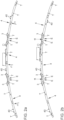
- the Fig. 1a shows a first embodiment of a lighting unit 1, wherein the lighting unit 1 is arranged under a cover-like component 10.
- the cover-like part 10 is arranged in the area of a windshield W, of which only the course of the windshield is indicated.
- the lighting unit 1 extends over the entire length I of the panel-like component 10.
- the length I can, for example, extend over a substantial part of an instrument panel (not shown) in the region of the windshield W.
- the lighting unit 1 now consists of an elongated, also sickle-shaped light guide 2 (cf. Fig. 2 ), to which three circuit boards 4 are attached, preferably clipped.
- the circuit boards 4 are each placed against one another in the area of their ends in such a way that they overall follow the radius r1 of the lighting unit 1 or the curved shape of the light guide 2.
- Each of the circuit boards 4 is designed as a rigid circuit board, whereby all three circuit boards 4 have an identical radius r1.
- the circuit boards 4 lie against each other with their opposite ends E and thus form the desired radius r1.
- each circuit board 4 has three driver components T for controlling light-emitting diodes 40 arranged on the circuit boards 4.
- each driver unit T controls exactly six light-emitting diodes 40.
- a total of 54 light-emitting diodes can thus be controlled by the three circuit boards 4 arranged in a row and arranged in a sickle shape under a light coupling surface of the light guide 2.
- An angular offset ⁇ of successive light-emitting diodes 40, 40' in the longitudinal direction l caused by different angular positions of the circuit boards 4 can be compensated at the given points by a corresponding change in thickness ⁇ d of a base body 20 of the light guide 2 in the area of the light coupling surface 21.
- Fig. 3 a light-emitting diode 40 in the cutting plane and a subsequent light-emitting diode 40' with an angular offset ⁇ .
- a series of the three circuit boards 4 is shown in a somewhat narrower radius of curvature r2, as is necessary for a more strongly curved lighting unit 1' in a shutter-like component 10'.
- the light guide 2 preferably clipped to it (as in Fig. 2 shown), not only three rigid circuit boards 4, but even shorter, equally rigid circuit boards are lined up and also connected to one another via cables 3 (not shown in more detail).
- the light guide 2 preferably clipped to it (as in Fig. 2 shown)
- not only three rigid circuit boards 4 but even shorter, equally rigid circuit boards are lined up and also connected to one another via cables 3 (not shown in more detail).
- nine circuit boards are lined up and each circuit board has only one driver module T, to which only six LEDs 40 are assigned for control.
Landscapes
- Engineering & Computer Science (AREA)
- General Engineering & Computer Science (AREA)
- Mechanical Engineering (AREA)
- Microelectronics & Electronic Packaging (AREA)
- Arrangements Of Lighting Devices For Vehicle Interiors, Mounting And Supporting Thereof, Circuits Therefore (AREA)
Description
- Die Erfindung betrifft eine Beleuchtungseinheit für ein Kraftfahrzeug mit den Merkmalen vom Oberbegriff des Patentanspruchs 1.
- Eine derartige Beleuchtungseinheit ist aus der
US 8 164 016 B2 bekannt geworden. Darin wird ein Start/Stoppschalter für ein Kraftfahrzeug beschrieben, welcher eine Beleuchtungseinheit, die aus einer Leiterplatte mit mehreren LEDs und den LEDs zugeordneten Lichtleitern besteht. Die Verbindung zwischen der Leiterplatte und den Lichtleitern erfolgt über eine Rastverbindung. - Aus der
DE 10 2013 018 784 A1 ist eine längsförmige Beleuchtungsvorrichtung eines Fahrzeugs bekannt geworden. Konkret weist das offenbarte Kraftfahrzeug eine längsförmige Beleuchtungseinrichtung zum Erzeugen eines Leuchtstreifens entlang einer vorgegebenen Strecke der Beleuchtungseinrichtung auf. Dazu weist die Beleuchtungsvorrichtung einen ebenso längsförmigen Lichtleiter auf, in den Licht von Leuchtdioden einkoppelbar ist. Ein erster Abschnitt der Beleuchtungseinrichtung ist am Interieur des Fahrzeugs und ein zweiter Abschnitt an einem äußeren Bauteil des Kraftfahrzeugs, beispielsweise an einer Fahrzeugtür, einer Motorhaube oder einem Außenspiegel angeordnet ist. - In der
EP 0 818 652 A2 ist eine Beleuchtungsleiste mit einem mehradrigen Leiterstreifen beschrieben, der mit in Reihe hintereinander angeordneten Leuchtdioden bestückt ist. Der Leiterstreifen besteht aus einer Vielzahl von abgelängten, in axialer Richtung aneinander gereihten Leiterstreifenabschnitten. Zwischen zwei axial aneinandergrenzenden Leiterstreifenabschnitten ist jeweils eine mit einer Leuchtdiode bestückte Leiterplatte mit diesen elektrisch leitend verbunden. Die elektrische Verbindung zwischen den Leiterstreifen und Kontakten der Leiterplatte erfolgt über eine Crimp- und eine Nietverbindung. Die Herstellung der mit dem Leiterplatten verbundenen Leiterstreifen wird über mehrere Fertigungsstationen in der Form eines Endlosstreifens bewerkstelligt. - Schließlich wird in der
US 7 477 140 B1 eine Beleuchtungseinrichtung für ein Kraftfahrzeugfenster beschrieben. Die Beleuchtungsvorrichtung weist eine Vielzahl von matrixartig angeordneten Leuchtpixeln auf, die durch Leuchtdioden gebildet werden, welche entlang von zeilenartig untereinander angeordneten Leiterplatten, welche sich über die Längsrichtung der Anzeigevorrichtung erstrecken, angeordnet sind. - Gattungsgemäße Beleuchtungseinheiten sind auch in den Offenlegungsschriften
DE 10 2015 220 843 A1 undEP 1 743 801 A1 offenbart. - Der vorliegenden Erfindung liegt die Aufgabe zu Grunde, eine Beleuchtungseinheit für ein Kraftfahrzeug bereitzustellen, welche im Innenraum eines Kraftfahrzeugs im Bereich einer Frontscheibe eine gute Signalwirkung für einen Fahrzeuginsassen bereitstellen kann, dem Verlauf der Frontscheibe in Fahrzeugquerrichtung angepasst ist und dennoch kostengünstig herstellbar ist.
- Vorliegende Aufgabe wird mit einer Beleuchtungseinheit mit den Merkmalen von Patentanspruch 1 gelöst. Vorteilhafte Ausbildungen der Erfindung sind den jeweils abhängigen Ansprüchen zu entnehmen.
- Die Erfindung geht zunächst aus von einer Beleuchtungseinheit für ein Kraftfahrzeug, vorzugsweise für den Innenraum des Kraftfahrzeugs, aus wenigstens einem Lichtleiter und wenigstens einer wenigstens eine Leuchtdiode aufweisenden Leiterplatte. Die Leiterplatte und der Lichtleiter sind aneinander befestigt.
- Die Erfindung sieht nun vor, dass die Beleuchtungseinheit längsförmig und sichelartig gebogen ausgebildet ist mit einem sich über die Länge der Beleuchtungseinheit erstreckenden Lichtleiter. Ferner weist die Beleuchtungseinheit mehrere längliche, starre Leiterplatten auf, die jeweils mit mehreren Leuchtdioden bestückt sind, wobei die Leiterplatten identisch aufgebaut und in ihrer Längsrichtung entlang dem Lichtleiter aneinandergereiht sind, derart, dass das Licht der Leuchtdioden senkrecht zur Längserstreckung des Lichtleiters in diesen einkoppelbar ist. Dabei sind die Leiterplatten über Kabel elektrisch und signaltechnisch miteinander verbunden. Zur elektrischen Kontaktierung können die Kabel mit den Leiterplatten bspw. verlötet oder über Steckverbinder verbunden sein.
- Auf diese Weise wird eine Beleuchtungseinheit bereitgestellt, die als längliche Beleuchtungseinheit im Bereich einer Frontscheibe eine gute Signalwirkung für einen Fahrzeuginsassen erzeugen kann und kostengünstig auf unterschiedliche Scheibenkrümmungen auf Grund von vorgegebenen Designanforderungen anpassbar ist. Dennoch ist es möglich, für unterschiedliche Fahrzeugtypen die gleichen Elektronikkomponenten zu benutzen.
- Denn durch die flexible elektrische Anbindung der Leiterplatten an ihren Enden sowie die elektrische Verbindung mittels Steckverbindern wird eine leichte Anpassung an die erforderlichen Geometrien gewährleistet.
- Eine erste Weiterbildung der Erfindung schlägt vor, dass die Leiterplatten über die Kabel im Bereich ihrer gegenüberliegenden Enden verbunden sind, wobei die gegenüberliegenden Enden aneinander anliegen oder allenfalls nur in einem solchen geringen Abstand gegenüberliegen, der ein Vielfaches kleiner ist als eine Länge einer Leiterplatte.
- Diese Ausgestaltung ermöglicht trotz Verwendung mehrerer Leiterplatten eine gleiche Beabstandung der Leuchtdioden auch im Übergangsbereich zwischen den Leiterplatten.
- Erfindungsgemäß weist jede Leiterplatte im Umriss eine gebogene Form mit einem Krümmungsradius auf. Diese Ausgestaltung trägt dazu bei, dass die Leiterplatten auf leichtere Weise einer gewünschten Kontur der Beleuchtungseinheit angepasst werden können.
- Durch die Verwendung von starren Leiterplatten können diese präzise zum Lichtleiter positioniert werden. Der Lichtleiter selbst kann als Spritzgussformteil eine Geometrie aufweisen, die unterschiedliche Positionen der LEDs relativ zu einer Lichtaustrittsfläche, welche sich ebenfalls in Längsrichtung des Lichtleiters und damit der Beleuchtungseinheit hinzieht, kompensiert.
- Es ist denkbar, dass jede Leiterplatte mehrere Treibereinheiten aufweist, wobei jeder Treibereinheit ein Teil von den mehreren Leuchtdioden der Leiterplatte zugeordnet ist. Hierdurch wird die Voraussetzung geschaffen, dass das Handling für die Montage und für die Verbindung der einzelnen Leiterplatten mit dem Lichtleiter erleichtert wird. Die Teile der durch die Treibereinheiten angesteuerten Leuchtdioden sind in der Anzahl vorzugsweise gleich.
- So ist denkbar, dass drei Leiterplatten vorhanden sind und auf jeder Leiterplatte 18 Leuchtdioden und drei Treibereinheiten angeordnet sind. Jede Treibereinheit treibt dabei sechs Leuchtdioden elektrisch und signaltechnisch an, ist also diesen zugeordnet.
- Es ist auch vorstellbar, dass jede Leiterplatte eine Treibereinheit aufweist, wobei der Treibereinheit alle Leuchtdioden der Leiterplatte zur Ansteuerung zugeordnet sind. Diese Ausgestaltung ermöglicht eine kürzere Länge der Leiterplatten und damit eine erhöhte Flexibilität in der Ausrichtung.
- Für diesen Fall ist denkbar, dass bei der Beleuchtungseinheit neun Leiterplatten vorhanden sind und auf jeder Leiterplatte sechs Leuchtdioden angeordnet sind, die der auf der Leiterplatte vorhandenen Treibereinheit zur Ansteuerung zugeordnet sind.
- Eine andere Weiterbildung schlägt vor, dass die Leiterplatten derart aneinandergereiht sind, dass die Krümmung wenigstens einer Leiterplatte der Krümmung einer anderen Leiterplatte entgegengerichtet ist. Hierdurch wird es ermöglicht auch eine Beleuchtungseinheit mit nur einer äußerst geringen Biegung zu realisieren.
- Die vorliegende Erfindung soll auch ein Kraftfahrzeug unter Schutz stellen, welche mit wenigstens einer erfindungsgemäßen Beleuchtungsvorrichtung ausgestattet ist.
- Bevorzugte Ausführungsbeispiele der Erfindung sind in den Figuren dargestellt und werden anhand der Figuren in der nachfolgenden Beschreibung näher erläutert. Dadurch werden auch noch weitere Vorteile der Erfindung deutlich. Gleiche Bezugszeichen, auch in unterschiedlichen Figuren, beziehen sich auf gleiche, vergleichbare oder funktional gleiche Bauteile. Dabei werden entsprechende oder vergleichbare Eigenschaften und Vorteile erreicht, auch wenn eine wiederholte Beschreibung oder Bezugnahme darauf nicht erfolgt. Die Figuren sind nicht oder zumindest nicht immer maßstabsgetreu. In manchen Figuren können Proportionen oder Abstände übertrieben dargestellt sein, um Merkmale eines Ausführungsbeispiels deutlicher hervorheben zu können.
- Es zeigen, jeweils schematisch
- Figuren 1
- zwei Beleuchtungseinheiten mit unterschiedlichen Krümmungsradien,
- Figuren 2
- die Darstellung einer unterschiedlichen Ausrichtung von starren, aneinander gereihten Leiterplatten gemäß unterschiedlichen Radien der Beleuchtungseinheiten und
- Figur 3
- einen Schnitt gemäß Schnittverlauf II aus
Fig. 1a . - Die
Fig. 1a zeigt ein erstes Ausführungsbeispiel für eine Beleuchtungseinheit 1, wobei unter einem blendenartigen Bauteil 10 die Beleuchtungseinheit 1 angeordnet ist. - Das blendenartige Teil 10 ist im Bereich einer Windschutzscheibe W angeordnet, von der nur der Strakverlauf angedeutet ist.
- Die Beleuchtungseinheit 1 erstreckt sich über die gesamte Länge I des blendenartigen Bauteils 10. Die Länge I kann sich beispielsweise über einen wesentlichen Teil einer Instrumententafel (nicht gezeigt) im Bereich der Windschutzscheibe W entlang ziehen.
- Die Beleuchtungseinheit 1 besteht nun aus einem langgestreckten, ebenso sichelförmig gebogenen Lichtleiter 2 (vgl.
Fig. 2 ), an dem drei Leiterplatten 4 befestigt, vorzugsweise verklipst sind. - Die Leiterplatten 4 sind jeweils im Bereich ihrer Enden so aneinandergelegt, dass sie insgesamt den Radius r1 der Beleuchtungseinheit 1 beziehungsweise die gebogene Form des Lichtleiters 2 nachführen.
- Jede der Leiterplatten 4 ist als starre Leiterplatte ausgebildet, wobei alle drei Leiterplatten 4 einen identisch Radius r1 aufweisen.
- Die Leiterplatten 4 liegen mit ihren gegenüberliegenden Enden E aneinander an und bilden so insgesamt den gewünschten Radius r1 aus.
- Im Ausführungsbeispiel weist jede Leiterplatte 4 drei Treiberbausteine T zur Ansteuerung von auf den Leiterplatten 4 angeordneten Leuchtdioden 40 auf. Dabei steuert jeweils eine Treibereinheit T genau sechs Leuchtdioden 40 an. Somit sind durch die drei aneinander gereihten Leiterplatten 4 insgesamt 54 Leuchtdioden ansteuerbar und sichelförmig unter einer Lichteinkoppelfläche des Lichtleiters 2 angeordnet.
- Ein durch unterschiedliche Winkelstellungen der Leiterplatten 4 zueinander bedingter Winkelversatz α von aufeinander in Längsrichtung l aufeinander folgenden Leuchtdioden 40, 40' (vergleiche
Fig. 2 ) kann an den gegebenen Stellen durch eine entsprechende Dickenveränderung Δd eines Grundkörpers 20 vom Lichtleiter 2 im Bereich der Lichteinkoppelfläche 21 ausgeglichen werden. Dabei sind inFig. 3 eine Leuchtdiode 40 in der Schnittebene und eine danach folgende Leuchtdiode 40' mit einem Winkelversatz α dargestellt. - In der
Fig. 2b ist eine Aneinanderreihung der drei Leiterplatten 4 in einem etwas engerem Krümmungsradius r2 dargestellt, so wie er für eine stärker gekrümmte Beleuchtungseinheit 1' in einem blendenartigen Bauteil 10' notwendig ist. - Wie anhand von
Fig. 2b ersichtlich ist, stehen zur Erzielung des Krümmungsradius r2 die gegenüberliegenden Enden E zweier aneinander gereihter Leiterplatten 4 etwas auseinander. Der Abstand ist allerdings nur geringfügig und um ein Vielfaches geringer als eine Länge jeder einzelnen Leiterplatte 4. - Abweichend vom Ausführungsbeispiel ist es auch denkbar, dass mit dem Lichtleiter 2, und zwar vorzugsweise mit diesem verklipst (wie in
Fig. 2 dargestellt), nicht nur drei starre Leiterplatten 4, sondern noch kürzere, ebenso starre Leiterplatten aneinandergereiht und miteinander ebenfalls über Kabel 3 verbunden werden (nicht näher dargestellt). Vorzugsweise ist es dabei denkbar, dass neun Leiterplatten angereiht werden und jede Leiterplatte nur einen Treiberbaustein T aufweist, dem jeweils nur sechs LEDs 40 zur Ansteuerung zugeordnet sind. - Der Vorteil bei dieser Lösung liegt in einer erhöhten Flexibilität der Anordnung, während der Vorteil der Aneinanderreihung von nur drei Leiterplatten 4 im erleichterten Handling liegt.
-
- 1, 1`
- Beleuchtungseinheit
- 2
- Lichtleiter
- 3
- Kabel
- 4
- Leiterplatten
- 10
- blendenartiges Bauteil
- 20
- Grundkörper
- 21
- Lichteinkoppelfläche
- 22
- Lichtauskoppelfläche
- 40
- Leuchtdioden
- A
- Winkelversatz
- F
- Fahrtrichtung
- L
- Licht
- I
- Längsrichtung
- r1, r2
- Radien
- T
- Treibereinheiten
- W
- Windschutzscheibe
- Δd
- Dickenänderung
Claims (7)
- Beleuchtungseinheit (1; 1') für ein Kraftfahrzeug aus wenigstens einem Lichtleiter (2) und wenigstens einer wenigstens eine Leuchtdiode (40) aufweisenden Leiterplatte (4), wobei die Leiterplatte (4) und der Lichtleiter (2) aneinander befestigt sind, wobei die Beleuchtungseinheit (1, 1') längsförmig und sichelartig gebogen ausgebildet ist mit einem sich über eine Länge (I) der Beleuchtungseinheit (1,1') erstreckenden Lichtleiter (2) und mehreren länglichen, starren Leiterplatten (4), die jeweils mit mehreren Leuchtdioden (40) bestückt sind, wobei die Leiterplatten (4) identisch aufgebaut und in ihrer Längsrichtung entlang dem Lichtleiter (2) aneinandergereiht sind, derart, dass Licht (L) der Leuchtdioden (40) senkrecht zur Längserstreckung des Lichtleiters (2) in diesen einkoppelbar ist, und wobei die Leiterplatten (4) über Kabel (3) elektrisch und signaltechnisch miteinander verbunden sind, dadurch gekennzeichnet dass die Leiterplatten (2) im Umriss jeweils eine gebogene Form mit einem Krümmungsradius (r1, r2) aufweisen.
- Beleuchtungseinheit (1, 1') nach Anspruch 1, dadurch gekennzeichnet, dass die Leiterplatten (4) über die Kabel (3) im Bereich ihrer gegenüberliegenden Enden (E) verbunden sind, wobei die gegenüberliegenden Enden (E) aneinander anliegen oder allenfalls nur in einem solchen geringen Abstand gegenüberliegen, der ein Vielfaches kleiner ist als eine Länge einer Leiterplatte (4).
- Beleuchtungseinheit (1,1') nach einem der vorhergehenden Ansprüche, dadurch gekennzeichnet, dass jede Leiterplatte (2) mehrere Treibereinheiten (T) aufweist, wobei jeder Treibereinheit (T) ein Teil von den mehreren Leuchtdioden (40) der Leiterplatte (2) zur Ansteuerung der Leuchtdioden (40) zugeordnet ist.
- Beleuchtungseinheit (1, 1') nach Anspruch 3, dadurch gekennzeichnet, dass drei Leiterplatten (4) vorhanden sind und auf jeder Leiterplatte (4) achtzehn Leuchtdioden (40) und drei Treibereinheiten (T) angeordnet sind, wobei jeder Treibereinheit (T) jeweils 6 Leuchtdioden (40) zugeordnet sind.
- Beleuchtungseinheit (1, 1') nach einem der vorhergehenden Ansprüche, dadurch gekennzeichnet, dass jede Leiterplatte (4) eine Treibereinheit (T) aufweist, wobei der Treibereinheit (T) alle Leuchtdioden (40) der Leiterplatte (4) zur Ansteuerung zugeordnet sind.
- Beleuchtungseinheit (1,1') nach Anspruch 5, dadurch gekennzeichnet, dass neun Leiterplatten (4) vorhanden sind und auf jeder Leiterplatte (4) sechs Leuchtdioden (40) angeordnet sind, die der Treibereinheit (T) zur Ansteuerung zugeordnet sind.
- Kraftfahrzeug, gekennzeichnet durch wenigstens eine Beleuchtungseinheit (1, 1') nach einem der vorhergehenden Ansprüche.
Applications Claiming Priority (2)
| Application Number | Priority Date | Filing Date | Title |
|---|---|---|---|
| DE102019203502.7A DE102019203502A1 (de) | 2019-03-14 | 2019-03-14 | Beleuchtungseinheit für ein Kraftfahrzeug |
| PCT/EP2020/055685 WO2020182573A1 (de) | 2019-03-14 | 2020-03-04 | Beleuchtungseinheit für ein kraftfahrzeug |
Publications (2)
| Publication Number | Publication Date |
|---|---|
| EP3938244A1 EP3938244A1 (de) | 2022-01-19 |
| EP3938244B1 true EP3938244B1 (de) | 2024-10-09 |
Family
ID=69845338
Family Applications (1)
| Application Number | Title | Priority Date | Filing Date |
|---|---|---|---|
| EP20711810.0A Active EP3938244B1 (de) | 2019-03-14 | 2020-03-04 | Beleuchtungseinheit für ein kraftfahrzeug |
Country Status (5)
| Country | Link |
|---|---|
| US (1) | US11433805B2 (de) |
| EP (1) | EP3938244B1 (de) |
| CN (1) | CN113557171A (de) |
| DE (1) | DE102019203502A1 (de) |
| WO (1) | WO2020182573A1 (de) |
Families Citing this family (1)
| Publication number | Priority date | Publication date | Assignee | Title |
|---|---|---|---|---|
| EP4265961B1 (de) * | 2022-04-22 | 2025-05-28 | Marelli Automotive Lighting Italy S.p.A. Con Socio Unico | Kfz-beleuchtungseinrichtung und zugehöriges herstellungsverfahren |
Family Cites Families (26)
| Publication number | Priority date | Publication date | Assignee | Title |
|---|---|---|---|---|
| JP3177406B2 (ja) * | 1995-06-22 | 2001-06-18 | 株式会社沖データ | Ledプリントヘッド及びその焦点調整方法 |
| DE19627856A1 (de) | 1996-07-11 | 1998-01-15 | Happich Fahrzeug & Ind Teile | Beleuchtungsleiste und Verfahren zur Herstellung |
| AT407464B (de) * | 1999-07-23 | 2001-03-26 | Chip & Byte Datentechnik Ges M | Verfahren zur bestückung von leiterplatten mit leuchtdioden |
| US7477140B1 (en) | 2003-12-26 | 2009-01-13 | Booth Kenneth C | See-through lighted information display |
| ATE365360T1 (de) * | 2004-05-03 | 2007-07-15 | Lumino Gmbh Licht Elektronik | Anzeigevorrichtung |
| FR2872256B1 (fr) * | 2004-06-24 | 2008-12-12 | Valeo Vision Sa | Dispositif d'eclairage et/ou de signalisation a guide optique pour vehicule automobile |
| JP2007022325A (ja) * | 2005-07-15 | 2007-02-01 | Fujikura Ltd | 車両用ドアの照明装置 |
| EP1832902A1 (de) * | 2006-03-10 | 2007-09-12 | Delphi Technologies, Inc. | Flache Leuchtvorrichtung |
| DE102007035241B4 (de) | 2007-07-25 | 2017-01-19 | Huf Hülsbeck & Fürst Gmbh & Co. Kg | Schaltvorrichtung |
| KR100911236B1 (ko) * | 2007-08-22 | 2009-08-06 | 주식회사 플라켐 | 블록형 엘이디 조명장치 |
| EP2463153B1 (de) * | 2010-12-10 | 2015-04-15 | SMR Patents S.à.r.l. | Beleuchtungseinheit |
| CN102616178A (zh) * | 2011-01-31 | 2012-08-01 | 欧司朗光电半导体有限公司 | 用于车辆天窗的发光装置以及用于车辆的天窗 |
| US8920007B2 (en) * | 2011-09-06 | 2014-12-30 | Sonar Auto Parts Co., Ltd. | Vehicle lighting device |
| CN103244869A (zh) * | 2012-02-14 | 2013-08-14 | 胜华科技股份有限公司 | 光源装置 |
| DE102013018784B4 (de) | 2013-11-08 | 2016-02-18 | Audi Ag | Fahrzeug mit Beleuchtungsvorrichtung mit einer längsförmigen Beleuchtungseinrichtung |
| TWM483899U (zh) * | 2014-04-28 | 2014-08-11 | San Yuan Design Co Ltd | 電鍍透光後牌照飾板 |
| KR20150138707A (ko) * | 2014-06-02 | 2015-12-10 | 엘지이노텍 주식회사 | 광원 모듈 및 이를 이용하는 조명 장치 |
| JP6548887B2 (ja) * | 2014-10-24 | 2019-07-24 | スタンレー電気株式会社 | 車両用灯具 |
| DE102015220843A1 (de) * | 2015-10-26 | 2017-04-27 | Volkswagen Aktiengesellschaft | Innenbeleuchtung für ein Fahrzeug |
| DE102016121047B4 (de) * | 2015-11-06 | 2021-07-01 | Lisa Dräxlmaier GmbH | Herstellungsverfahren für eine beleuchtungseinrichtung |
| DE102015222505A1 (de) * | 2015-11-16 | 2017-05-18 | Bayerische Motoren Werke Aktiengesellschaft | Beleuchtungsvorrichtung für ein Kraftfahrzeug |
| DE102016119987B4 (de) * | 2016-10-20 | 2023-07-27 | Pictiva Displays International Limited | Verfahren zur Herstellung einer gebogenen organischen Leuchtdiode und gebogene organische Leuchtdiode |
| CN107994109A (zh) * | 2016-10-27 | 2018-05-04 | 佛山市国星光电股份有限公司 | 一种cob显示模组及其制造方法 |
| DE102017103296A1 (de) * | 2017-02-17 | 2018-08-23 | Webasto SE | Scheibenanordnung mit Beleuchtungseinrichtung |
| CN107367787B (zh) * | 2017-09-22 | 2019-06-18 | 青岛海信电器股份有限公司 | 曲面背光异型导光板、曲面背光模组及曲面液晶显示器 |
| CN109387900A (zh) * | 2018-11-27 | 2019-02-26 | 深圳市隆利科技股份有限公司 | 可调节出射光角度的导光板、背光模组以及液晶显示装置 |
-
2019
- 2019-03-14 DE DE102019203502.7A patent/DE102019203502A1/de not_active Withdrawn
-
2020
- 2020-03-04 EP EP20711810.0A patent/EP3938244B1/de active Active
- 2020-03-04 CN CN202080019985.6A patent/CN113557171A/zh active Pending
- 2020-03-04 WO PCT/EP2020/055685 patent/WO2020182573A1/de not_active Ceased
-
2021
- 2021-09-14 US US17/474,627 patent/US11433805B2/en active Active
Also Published As
| Publication number | Publication date |
|---|---|
| US11433805B2 (en) | 2022-09-06 |
| WO2020182573A1 (de) | 2020-09-17 |
| EP3938244A1 (de) | 2022-01-19 |
| US20220017011A1 (en) | 2022-01-20 |
| DE102019203502A1 (de) | 2020-09-17 |
| CN113557171A (zh) | 2021-10-26 |
Similar Documents
| Publication | Publication Date | Title |
|---|---|---|
| DE3612576C1 (de) | Elektrisches Bauteil mit Kunststoffmantel und Verfahren zu dessen Herstellung | |
| EP2924479B1 (de) | Fahrzeugscheinwerfer mit Lichtkopplungsschutz zwischen Lichtfunktionen | |
| DE102010056462A1 (de) | Wischblatt zum Reinigen von Scheiben von Kraftfahrzeugen | |
| EP1709359B1 (de) | Verformbares beleuchtungsmodul | |
| DE102016121047B4 (de) | Herstellungsverfahren für eine beleuchtungseinrichtung | |
| DE202009014251U1 (de) | System zur Verbindung elektrischer Leiter mit voneinander verschiedenen Potentialen sowie Steckadapter für das System | |
| DE202015102586U1 (de) | Bezeichnungsschilderstreifen für eine Reihe nebeneinander angeordneter elektrischer Klemmen und Anordnung | |
| EP1162631B1 (de) | Stecker zur Kontaktierung eines Flachbandkabels | |
| DE102013215823B4 (de) | Clipsbefestigungsvorrichtung, insbesondere für Kraftfahrzeuge | |
| EP3938244B1 (de) | Beleuchtungseinheit für ein kraftfahrzeug | |
| WO2011023286A1 (de) | Verbindungsanordnung für elektrische baugruppen | |
| EP2897230B1 (de) | Elektrische Steckverbindung insbesondere einer elektrischen Heizvorrichtung für ein Kraftfahrzeug | |
| DE10351462B4 (de) | Fahrzeugleuchte | |
| EP1499002A2 (de) | Encodersystem und Verfahren zur Montage eines Encodersystems | |
| EP1467431B1 (de) | Kontaktadapter für die Kontaktierung einer Antennenstruktur eines Fahrzeuges | |
| DE102012101574B4 (de) | Montageanordnung einer Anzeigevorrichtung und Verfahren der Montage der Anzeigevorrichtung | |
| DE102021213198A1 (de) | Kabelsatz sowie Verfahren zur Herstellung eines Kabelsatzes | |
| DE19846738A1 (de) | Anbindungselement für Seilzüge | |
| EP4542792A1 (de) | Adapter für ein schienenleuchtensystem sowie beleuchtungsanordnung | |
| DE102019007253A1 (de) | Elektrifizierte Leistenanordnung | |
| DE10225543A1 (de) | Träger für Leuchtelemente in einer Kraftfahrzeugleuchte | |
| DE102017131316A1 (de) | Modular aufgebauter Leiterplattenverbund | |
| DE102018120104B4 (de) | Steckverbinder zum Bereitstellen eines elektrischen Anschlusses und Verfahren | |
| DE10227996A1 (de) | Getriebe-Antriebseinheit mit Rastelement | |
| EP3663635B1 (de) | Entblendeter linsenstabilisator |
Legal Events
| Date | Code | Title | Description |
|---|---|---|---|
| STAA | Information on the status of an ep patent application or granted ep patent |
Free format text: STATUS: UNKNOWN |
|
| STAA | Information on the status of an ep patent application or granted ep patent |
Free format text: STATUS: THE INTERNATIONAL PUBLICATION HAS BEEN MADE |
|
| PUAI | Public reference made under article 153(3) epc to a published international application that has entered the european phase |
Free format text: ORIGINAL CODE: 0009012 |
|
| STAA | Information on the status of an ep patent application or granted ep patent |
Free format text: STATUS: REQUEST FOR EXAMINATION WAS MADE |
|
| 17P | Request for examination filed |
Effective date: 20211014 |
|
| AK | Designated contracting states |
Kind code of ref document: A1 Designated state(s): AL AT BE BG CH CY CZ DE DK EE ES FI FR GB GR HR HU IE IS IT LI LT LU LV MC MK MT NL NO PL PT RO RS SE SI SK SM TR |
|
| DAV | Request for validation of the european patent (deleted) | ||
| DAX | Request for extension of the european patent (deleted) | ||
| GRAP | Despatch of communication of intention to grant a patent |
Free format text: ORIGINAL CODE: EPIDOSNIGR1 |
|
| STAA | Information on the status of an ep patent application or granted ep patent |
Free format text: STATUS: GRANT OF PATENT IS INTENDED |
|
| INTG | Intention to grant announced |
Effective date: 20240513 |
|
| GRAS | Grant fee paid |
Free format text: ORIGINAL CODE: EPIDOSNIGR3 |
|
| GRAA | (expected) grant |
Free format text: ORIGINAL CODE: 0009210 |
|
| STAA | Information on the status of an ep patent application or granted ep patent |
Free format text: STATUS: THE PATENT HAS BEEN GRANTED |
|
| AK | Designated contracting states |
Kind code of ref document: B1 Designated state(s): AL AT BE BG CH CY CZ DE DK EE ES FI FR GB GR HR HU IE IS IT LI LT LU LV MC MK MT NL NO PL PT RO RS SE SI SK SM TR |
|
| REG | Reference to a national code |
Ref country code: CH Ref legal event code: EP |
|
| REG | Reference to a national code |
Ref country code: DE Ref legal event code: R096 Ref document number: 502020009424 Country of ref document: DE |
|
| REG | Reference to a national code |
Ref country code: IE Ref legal event code: FG4D Free format text: LANGUAGE OF EP DOCUMENT: GERMAN |
|
| P01 | Opt-out of the competence of the unified patent court (upc) registered |
Free format text: CASE NUMBER: APP_56923/2024 Effective date: 20241018 |
|
| REG | Reference to a national code |
Ref country code: LT Ref legal event code: MG9D |
|
| REG | Reference to a national code |
Ref country code: NL Ref legal event code: MP Effective date: 20241009 |
|
| PG25 | Lapsed in a contracting state [announced via postgrant information from national office to epo] |
Ref country code: NL Free format text: LAPSE BECAUSE OF FAILURE TO SUBMIT A TRANSLATION OF THE DESCRIPTION OR TO PAY THE FEE WITHIN THE PRESCRIBED TIME-LIMIT Effective date: 20241009 |
|
| PG25 | Lapsed in a contracting state [announced via postgrant information from national office to epo] |
Ref country code: NL Free format text: LAPSE BECAUSE OF FAILURE TO SUBMIT A TRANSLATION OF THE DESCRIPTION OR TO PAY THE FEE WITHIN THE PRESCRIBED TIME-LIMIT Effective date: 20241009 |
|
| PG25 | Lapsed in a contracting state [announced via postgrant information from national office to epo] |
Ref country code: PT Free format text: LAPSE BECAUSE OF FAILURE TO SUBMIT A TRANSLATION OF THE DESCRIPTION OR TO PAY THE FEE WITHIN THE PRESCRIBED TIME-LIMIT Effective date: 20250210 Ref country code: HR Free format text: LAPSE BECAUSE OF FAILURE TO SUBMIT A TRANSLATION OF THE DESCRIPTION OR TO PAY THE FEE WITHIN THE PRESCRIBED TIME-LIMIT Effective date: 20241009 Ref country code: IS Free format text: LAPSE BECAUSE OF FAILURE TO SUBMIT A TRANSLATION OF THE DESCRIPTION OR TO PAY THE FEE WITHIN THE PRESCRIBED TIME-LIMIT Effective date: 20250209 |
|
| PG25 | Lapsed in a contracting state [announced via postgrant information from national office to epo] |
Ref country code: FI Free format text: LAPSE BECAUSE OF FAILURE TO SUBMIT A TRANSLATION OF THE DESCRIPTION OR TO PAY THE FEE WITHIN THE PRESCRIBED TIME-LIMIT Effective date: 20241009 |
|
| PG25 | Lapsed in a contracting state [announced via postgrant information from national office to epo] |
Ref country code: BG Free format text: LAPSE BECAUSE OF FAILURE TO SUBMIT A TRANSLATION OF THE DESCRIPTION OR TO PAY THE FEE WITHIN THE PRESCRIBED TIME-LIMIT Effective date: 20241009 |
|
| PG25 | Lapsed in a contracting state [announced via postgrant information from national office to epo] |
Ref country code: ES Free format text: LAPSE BECAUSE OF FAILURE TO SUBMIT A TRANSLATION OF THE DESCRIPTION OR TO PAY THE FEE WITHIN THE PRESCRIBED TIME-LIMIT Effective date: 20241009 |
|
| PG25 | Lapsed in a contracting state [announced via postgrant information from national office to epo] |
Ref country code: NO Free format text: LAPSE BECAUSE OF FAILURE TO SUBMIT A TRANSLATION OF THE DESCRIPTION OR TO PAY THE FEE WITHIN THE PRESCRIBED TIME-LIMIT Effective date: 20250109 |
|
| PG25 | Lapsed in a contracting state [announced via postgrant information from national office to epo] |
Ref country code: LV Free format text: LAPSE BECAUSE OF FAILURE TO SUBMIT A TRANSLATION OF THE DESCRIPTION OR TO PAY THE FEE WITHIN THE PRESCRIBED TIME-LIMIT Effective date: 20241009 Ref country code: GR Free format text: LAPSE BECAUSE OF FAILURE TO SUBMIT A TRANSLATION OF THE DESCRIPTION OR TO PAY THE FEE WITHIN THE PRESCRIBED TIME-LIMIT Effective date: 20250110 |
|
| PG25 | Lapsed in a contracting state [announced via postgrant information from national office to epo] |
Ref country code: PL Free format text: LAPSE BECAUSE OF FAILURE TO SUBMIT A TRANSLATION OF THE DESCRIPTION OR TO PAY THE FEE WITHIN THE PRESCRIBED TIME-LIMIT Effective date: 20241009 |
|
| PG25 | Lapsed in a contracting state [announced via postgrant information from national office to epo] |
Ref country code: RS Free format text: LAPSE BECAUSE OF FAILURE TO SUBMIT A TRANSLATION OF THE DESCRIPTION OR TO PAY THE FEE WITHIN THE PRESCRIBED TIME-LIMIT Effective date: 20250109 |
|
| PG25 | Lapsed in a contracting state [announced via postgrant information from national office to epo] |
Ref country code: SM Free format text: LAPSE BECAUSE OF FAILURE TO SUBMIT A TRANSLATION OF THE DESCRIPTION OR TO PAY THE FEE WITHIN THE PRESCRIBED TIME-LIMIT Effective date: 20241009 |
|
| PG25 | Lapsed in a contracting state [announced via postgrant information from national office to epo] |
Ref country code: DK Free format text: LAPSE BECAUSE OF FAILURE TO SUBMIT A TRANSLATION OF THE DESCRIPTION OR TO PAY THE FEE WITHIN THE PRESCRIBED TIME-LIMIT Effective date: 20241009 |
|
| REG | Reference to a national code |
Ref country code: DE Ref legal event code: R097 Ref document number: 502020009424 Country of ref document: DE |
|
| PG25 | Lapsed in a contracting state [announced via postgrant information from national office to epo] |
Ref country code: EE Free format text: LAPSE BECAUSE OF FAILURE TO SUBMIT A TRANSLATION OF THE DESCRIPTION OR TO PAY THE FEE WITHIN THE PRESCRIBED TIME-LIMIT Effective date: 20241009 |
|
| PG25 | Lapsed in a contracting state [announced via postgrant information from national office to epo] |
Ref country code: RO Free format text: LAPSE BECAUSE OF FAILURE TO SUBMIT A TRANSLATION OF THE DESCRIPTION OR TO PAY THE FEE WITHIN THE PRESCRIBED TIME-LIMIT Effective date: 20241009 |
|
| PG25 | Lapsed in a contracting state [announced via postgrant information from national office to epo] |
Ref country code: SK Free format text: LAPSE BECAUSE OF FAILURE TO SUBMIT A TRANSLATION OF THE DESCRIPTION OR TO PAY THE FEE WITHIN THE PRESCRIBED TIME-LIMIT Effective date: 20241009 |
|
| PG25 | Lapsed in a contracting state [announced via postgrant information from national office to epo] |
Ref country code: CZ Free format text: LAPSE BECAUSE OF FAILURE TO SUBMIT A TRANSLATION OF THE DESCRIPTION OR TO PAY THE FEE WITHIN THE PRESCRIBED TIME-LIMIT Effective date: 20241009 |
|
| PG25 | Lapsed in a contracting state [announced via postgrant information from national office to epo] |
Ref country code: IT Free format text: LAPSE BECAUSE OF FAILURE TO SUBMIT A TRANSLATION OF THE DESCRIPTION OR TO PAY THE FEE WITHIN THE PRESCRIBED TIME-LIMIT Effective date: 20241009 |
|
| PLBE | No opposition filed within time limit |
Free format text: ORIGINAL CODE: 0009261 |
|
| STAA | Information on the status of an ep patent application or granted ep patent |
Free format text: STATUS: NO OPPOSITION FILED WITHIN TIME LIMIT |
|
| PG25 | Lapsed in a contracting state [announced via postgrant information from national office to epo] |
Ref country code: SE Free format text: LAPSE BECAUSE OF FAILURE TO SUBMIT A TRANSLATION OF THE DESCRIPTION OR TO PAY THE FEE WITHIN THE PRESCRIBED TIME-LIMIT Effective date: 20241009 |
|
| 26N | No opposition filed |
Effective date: 20250710 |
|
| PG25 | Lapsed in a contracting state [announced via postgrant information from national office to epo] |
Ref country code: MC Free format text: LAPSE BECAUSE OF FAILURE TO SUBMIT A TRANSLATION OF THE DESCRIPTION OR TO PAY THE FEE WITHIN THE PRESCRIBED TIME-LIMIT Effective date: 20241009 |
|
| REG | Reference to a national code |
Ref country code: CH Ref legal event code: H13 Free format text: ST27 STATUS EVENT CODE: U-0-0-H10-H13 (AS PROVIDED BY THE NATIONAL OFFICE) Effective date: 20251024 |
|
| PG25 | Lapsed in a contracting state [announced via postgrant information from national office to epo] |
Ref country code: LU Free format text: LAPSE BECAUSE OF NON-PAYMENT OF DUE FEES Effective date: 20250304 |
|
| REG | Reference to a national code |
Ref country code: BE Ref legal event code: MM Effective date: 20250331 |
|
| PG25 | Lapsed in a contracting state [announced via postgrant information from national office to epo] |
Ref country code: BE Free format text: LAPSE BECAUSE OF NON-PAYMENT OF DUE FEES Effective date: 20250331 |
|
| PG25 | Lapsed in a contracting state [announced via postgrant information from national office to epo] |
Ref country code: CH Free format text: LAPSE BECAUSE OF NON-PAYMENT OF DUE FEES Effective date: 20250331 |
|
| PG25 | Lapsed in a contracting state [announced via postgrant information from national office to epo] |
Ref country code: IE Free format text: LAPSE BECAUSE OF NON-PAYMENT OF DUE FEES Effective date: 20250304 |
|
| PGFP | Annual fee paid to national office [announced via postgrant information from national office to epo] |
Ref country code: GB Payment date: 20260323 Year of fee payment: 7 |
|
| PGFP | Annual fee paid to national office [announced via postgrant information from national office to epo] |
Ref country code: DE Payment date: 20260331 Year of fee payment: 7 |
|
| PGFP | Annual fee paid to national office [announced via postgrant information from national office to epo] |
Ref country code: FR Payment date: 20260323 Year of fee payment: 7 |