EP3936746A1 - Durchflussumschaltventil und flüssigkeitschromatograph damit - Google Patents
Durchflussumschaltventil und flüssigkeitschromatograph damit Download PDFInfo
- Publication number
- EP3936746A1 EP3936746A1 EP19918087.8A EP19918087A EP3936746A1 EP 3936746 A1 EP3936746 A1 EP 3936746A1 EP 19918087 A EP19918087 A EP 19918087A EP 3936746 A1 EP3936746 A1 EP 3936746A1
- Authority
- EP
- European Patent Office
- Prior art keywords
- flow passage
- stator
- rotor seal
- end portion
- switching valve
- Prior art date
- Legal status (The legal status is an assumption and is not a legal conclusion. Google has not performed a legal analysis and makes no representation as to the accuracy of the status listed.)
- Granted
Links
Images








Classifications
-
- G—PHYSICS
- G01—MEASURING; TESTING
- G01N—INVESTIGATING OR ANALYSING MATERIALS BY DETERMINING THEIR CHEMICAL OR PHYSICAL PROPERTIES
- G01N30/00—Investigating or analysing materials by separation into components using adsorption, absorption or similar phenomena or using ion-exchange, e.g. chromatography or field flow fractionation
- G01N30/02—Column chromatography
- G01N30/26—Conditioning of the fluid carrier; Flow patterns
- G01N30/28—Control of physical parameters of the fluid carrier
- G01N30/32—Control of physical parameters of the fluid carrier of pressure or speed
-
- F—MECHANICAL ENGINEERING; LIGHTING; HEATING; WEAPONS; BLASTING
- F16—ENGINEERING ELEMENTS AND UNITS; GENERAL MEASURES FOR PRODUCING AND MAINTAINING EFFECTIVE FUNCTIONING OF MACHINES OR INSTALLATIONS; THERMAL INSULATION IN GENERAL
- F16K—VALVES; TAPS; COCKS; ACTUATING-FLOATS; DEVICES FOR VENTING OR AERATING
- F16K11/00—Multiple-way valves, e.g. mixing valves; Pipe fittings incorporating such valves
- F16K11/02—Multiple-way valves, e.g. mixing valves; Pipe fittings incorporating such valves with all movable sealing faces moving as one unit
- F16K11/06—Multiple-way valves, e.g. mixing valves; Pipe fittings incorporating such valves with all movable sealing faces moving as one unit comprising only sliding valves, i.e. sliding closure elements
- F16K11/072—Multiple-way valves, e.g. mixing valves; Pipe fittings incorporating such valves with all movable sealing faces moving as one unit comprising only sliding valves, i.e. sliding closure elements with pivoted closure members
- F16K11/074—Multiple-way valves, e.g. mixing valves; Pipe fittings incorporating such valves with all movable sealing faces moving as one unit comprising only sliding valves, i.e. sliding closure elements with pivoted closure members with flat sealing faces
- F16K11/0743—Multiple-way valves, e.g. mixing valves; Pipe fittings incorporating such valves with all movable sealing faces moving as one unit comprising only sliding valves, i.e. sliding closure elements with pivoted closure members with flat sealing faces with both the supply and the discharge passages being on one side of the closure plates
-
- F—MECHANICAL ENGINEERING; LIGHTING; HEATING; WEAPONS; BLASTING
- F16—ENGINEERING ELEMENTS AND UNITS; GENERAL MEASURES FOR PRODUCING AND MAINTAINING EFFECTIVE FUNCTIONING OF MACHINES OR INSTALLATIONS; THERMAL INSULATION IN GENERAL
- F16K—VALVES; TAPS; COCKS; ACTUATING-FLOATS; DEVICES FOR VENTING OR AERATING
- F16K37/00—Special means in or on valves or other cut-off apparatus for indicating or recording operation thereof, or for enabling an alarm to be given
- F16K37/0058—Optical means, e.g. light transmission, observation ports
-
- G—PHYSICS
- G01—MEASURING; TESTING
- G01N—INVESTIGATING OR ANALYSING MATERIALS BY DETERMINING THEIR CHEMICAL OR PHYSICAL PROPERTIES
- G01N30/00—Investigating or analysing materials by separation into components using adsorption, absorption or similar phenomena or using ion-exchange, e.g. chromatography or field flow fractionation
- G01N30/02—Column chromatography
- G01N2030/022—Column chromatography characterised by the kind of separation mechanism
- G01N2030/027—Liquid chromatography
-
- G—PHYSICS
- G01—MEASURING; TESTING
- G01N—INVESTIGATING OR ANALYSING MATERIALS BY DETERMINING THEIR CHEMICAL OR PHYSICAL PROPERTIES
- G01N30/00—Investigating or analysing materials by separation into components using adsorption, absorption or similar phenomena or using ion-exchange, e.g. chromatography or field flow fractionation
- G01N30/02—Column chromatography
- G01N30/04—Preparation or injection of sample to be analysed
- G01N30/16—Injection
- G01N30/20—Injection using a sampling valve
- G01N2030/202—Injection using a sampling valve rotary valves
-
- G—PHYSICS
- G01—MEASURING; TESTING
- G01N—INVESTIGATING OR ANALYSING MATERIALS BY DETERMINING THEIR CHEMICAL OR PHYSICAL PROPERTIES
- G01N30/00—Investigating or analysing materials by separation into components using adsorption, absorption or similar phenomena or using ion-exchange, e.g. chromatography or field flow fractionation
- G01N30/02—Column chromatography
- G01N30/26—Conditioning of the fluid carrier; Flow patterns
- G01N30/28—Control of physical parameters of the fluid carrier
- G01N30/32—Control of physical parameters of the fluid carrier of pressure or speed
- G01N2030/328—Control of physical parameters of the fluid carrier of pressure or speed valves, e.g. check valves of pumps
Definitions
- the present invention relates to a flow passage switching valve of an analyzer such as a liquid chromatograph, and a liquid chromatograph including the flow passage switching valve.
- a flow passage switching valve includes a stator that connects a pipe, a rotor seal, a rotor that rotates the rotor seal, and a housing that holds these members.
- the rotor is supported by a spring or the like.
- the rotor seal is pressed against the stator by the rotor so that liquid tightness of a rotor seal flow passage and a stator flow passage is maintained.
- the rotor seal is fixed to the rotor with a pin, and is rotated by a motor connected to the rotor to switch a flow passage.
- the flow passage switching valve that switches multiple flow passages is mounted on an analyzer such as a liquid chromatograph.
- PTL 1 discloses a flow passage switching valve having a structure that prevents abrasion of the flow passage end portion, for example.
- the flow passage switching valve disclosed in PTL 1 includes a stator and a rotor that has a surface in contact with one surface of the stator and rotates while sliding on the contact surface.
- the stator includes a plurality of liquid flow ports opening to the contact surface.
- the rotor includes a plurality of flow passage grooves connecting the liquid flow ports, and one flow passage groove into which a mobile phase solution flows in a load state and an injection state surrounds a rotation center of the rotor to be positioned on two sides with the rotation center of the rotor interposed therebetween.
- the flow passage switching valve is configured such that a flow passage groove connecting a high-pressure liquid flow port is positioned on the two sides with the rotation center of the rotor interposed therebetween.
- the invention provides a long-life flow passage switching valve that reduces abrasion caused by sliding of flow passage end portions of a stator and flow passage end portions of a rotor seal, and a liquid chromatograph having the flow passage switching valve.
- a flow passage switching valve includes : a stator; and a rotor seal connected with a rotor configured to rotate and slide on a circumference with respect to the stator.
- the stator has a plurality of stator flow passages that open to the rotor seal.
- the rotor seal has a rotor seal flow passage for coupling two or more stator flow passages among the plurality of stator flow passages.
- a flow passage end portion that is positioned at a tip end in a sliding direction of the rotor seal flow passage is positioned in a direction opposite to the sliding direction of the stator flow passage end portion to be connected to the rotor seal flow passage, at least at the start of sliding.
- a liquid chromatograph includes: a liquid feeding pump; a needle; a syringe pump; a flow passage switching valve; a flow separation column; and a detector.
- the flow passage switching valve includes: a stator; and a rotor seal connected with a rotor configured to rotate and slide on a circumference with respect to the stator.
- the stator has a plurality of stator flow passages that open to the rotor seal.
- the rotor seal has a rotor seal flow passage for coupling two or more stator flow passages among the plurality of stator flow passages.
- a flow passage end portion that is positioned at a tip end in a sliding direction of the rotor seal flow passage is positioned in a direction opposite to the sliding direction of the stator flow passage end portion to be connected to the rotor seal flow passage, at least at the start of sliding.
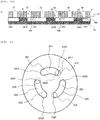
- FIG. 1A is a cross-sectional view of a flow passage switching valve of a first embodiment according to one embodiment of the invention.
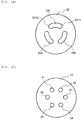
- FIG. 1B is a top view of a rotor seal constituting the flow passage switching valve shown in FIG. 1A .
- FIG. 1C is a top view of a portion, which is in contact with the rotor seal, of a stator constituting the flow passage switching valve shown in FIG. 1A .
- FIG. 1D is a top view of a contact surface between the stator and the rotor seal constituting the flow passage switching valve shown in FIG. 1A .
- a flow passage switching valve 5 includes a stator 21 that connects a pipe, a rotor seal 22, a rotor 23 that rotates the rotor seal 22, and a housing 26 that holds the stator 21 and the rotor 23.
- the roller 23 is supported by a spring or the like (not shown) .
- the stator 21 is usually made of metal or ceramic.
- the rotor seal 22 is made of metal, ceramic, or resin. It is desirable to coat the stator 21 and the rotor seal 22 with diamond-like carbon in order to improve an abrasion resistance performance.
- FIG. 1A a flow passage switching valve 5 includes a stator 21 that connects a pipe, a rotor seal 22, a rotor 23 that rotates the rotor seal 22, and a housing 26 that holds the stator 21 and the rotor 23.
- the roller 23 is supported by a spring or the like (not shown) .
- the stator 21 is usually made of metal or ceramic.
- the rotor seal 22 is
- a positioning window 27 is provided in a part of the housing 26, and is set as an initial value of positioning by a positioning hole 28 provided in a part of the rotor seal 22.
- the positioning hole 28 is not limited to a circular shape, and may be a concave portion having a rectangular shape.
- the rotor seal 22 is pressed against the stator 21 by the rotor 23 so that liquid tightness between a rotor seal flow passage 241 and a stator flow passage 31 and a stator flow passage 32, liquid tightness between a rotor seal flow passage 242 and a stator flow passage 35 and a stator flow passage 36, and liquid tightness between a rotor seal flow passage 243 and a stator flow passage 33 and a stator flow passage 34 are maintained.
- the rotor seal 22 is fixed to the rotor 23 by a pin (not shown) and is rotated by a motor (not shown) connected to the rotor 23.
- connection of the three rotor seal flow passages shown in FIG. 1B including the rotor seal flow passage 241, the rotor seal flow passage 242, and the rotor seal flow passage 243, and the six stator flow passages shown in FIG. 1C including the stator flow passage 31, the stator flow passage 32, the stator flow passage 33, the stator flow passage 34, the stator flow passage 35, and the stator flow passage 36 is switched.
- FIG. 1D When the stator 21 and the rotor seal 22 come into contact with each other, a result is as shown in FIG. 1D .
- FIG. 2 is an exploded view of a cross section of the stator flow passages and the rotor seal flow passages. A position of the cross section is indicated by a broken line 29 in FIG. 1D .
- FIG. 2A when a stator flow passage end portion 251, a stator flow passage end portion 252, a stator flow passage end portion 253, a stator flow passage end portion 254, a stator flow passage end portion 255, and a stator flow passage end portion 256 of the stator 21, a rotor seal flow passage end portion 2413, a rotor seal flow passage end portion 2423, and a rotor seal flow passage end portion 2433 of the rotor seal 22 come into contact with each other as shown in FIG. 2B , the liquid tightness of the stator flow passages 31 to 36 and the rotor seal flow passages 241 to 243 is maintained.
- FIG. 2C is an enlarged view of a contact portion 30 of FIG. 2B .
- loads 300 applied to flow passage end portions are concentrated on the stator flow passage end portion 251, the stator flow passage end portion 252, the stator flow passage end portion 253, the stator flow passage end portion 254, the stator flow passage end portion 255, the stator flow passage end portion 256, the rotor seal flow passage end portion 2413, the rotor seal flow passage end portion 2423, and the rotor seal flow passage end portion 2433 in FIG. 2B .
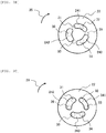
- FIGS. 3A , 3B, and 3C a positional relationship between stator flow passages and rotor seal flow passages when a rotor seal is rotated in the related art will be described with reference to FIGS. 3A , 3B, and 3C .
- the rotor seal 22 is rotated by 60 degrees in a sliding direction 29 in the clockwise direction, the process proceeds to FIG. 3C through FIG. 3B .
- the rotor seal 22 is rotated by 60 degrees in the sliding direction 29 in a right turn direction and the process proceeds to FIG. 3C through FIG. 3B .
- connection of the rotor seal flow passage 241 with the stator flow passage 31 and the stator flow passage 32 is switched to the connection with the stator flow passage 32 and the stator flow passage 33.
- connection of the rotor seal flow passage 242 with the stator flow passage 35 and the stator flow passage 36 is switched to the connection with the stator flow passages 36 and 31.
- the connection of the rotor seal flow passage 243 with the stator flow passage 33 and the stator flow passage 34 is switched to the connection with the stator flow passage 34 and the stator flow passage 35.
- FIG. 4A shows portions where stator flow passage end portions are scraped when the switching operation of FIG. 3 is performed.
- FIG. 4B shows portions where rotor seal flow passage end portions are scraped when the operation of FIG. 3 is performed.
- a flow passage end portion 2411 at a tip end in the rotor seal flow passage sliding direction is brought into contact with the stator flow passage end portion 253 twice
- a flow passage end portion 2412 at a tip end in the rotor seal flow passage sliding direction is brought into contact with the stator flow passage end portion 251 twice
- a flow passage end portion 2432 at a tip end in the rotor seal flow passage sliding direction is brought into contact with the stator flow passage end portion 253 twice
- a flow passage end portion 2431 at a tip end in the rotor seal flow passage sliding direction is brought into contact with the stator flow passage end portion 255 twice
- a flow passage end portion 2422 at the a end in the rotor seal flow passage sliding direction is brought into contact with the stator flow passage end portion 255 twice
- a flow passage end portion 2421 at a tip end in the rotor seal flow passage sliding direction is brought into contact with the stator flow passage end portion 251 twice.
- the stator flow passage end portion 253 is brought into contact with the flow passage end portion 2411 at the tip end in the rotor seal flow passage sliding direction and the flow passage end portion 2432 at the tip end in the rotor seal flow passage sliding direction four times in total.
- the stator flow passage end portion 251 is brought into contact with the flow passage end portion 2412 at the tip end in the rotor seal flow passage sliding direction and the flow passage end portion 2421 at the tip end in the rotor seal flow passage sliding direction four times in total.
- the stator flow passage end portion 255 is brought into contact with the flow passage end portion 2422 at the tip end in the rotor seal flow passage sliding direction and the flow passage end portion 2431 at the tip end in the rotor seal flow passage sliding direction and scraped four times in total.
- stator flow passage end portion 252, the stator flow passage end portion 254, and the stator flow passage end portion 256 are not scraped since the stator flow passage end portions are not brought into contact with the flow passage end portion 2411 at the tip end in the rotor seal flow passage sliding direction, the flow passage end portion 2412 at the tip end in the rotor seal flow passage sliding direction, the flow passage end portion 2421 at the tip end in the rotor seal flow passage sliding direction, the flow passage end portion 2422 at the tip end in the rotor seal flow passage sliding direction, the flow passage end portion 2431 at the tip end in the rotor seal flow passage sliding direction, and the flow passage end portion 2432 at the tip end in the rotor seal flow passage sliding direction.
- the flow passage end portions at the tip ends in the rotor seal flow passage sliding direction slide after being positioned in an opposite direction of the sliding direction of the stator flow passage end portions connected at the start of sliding.
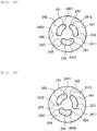
- FIG. 5A when the rotor seal flow passage 241, the rotor seal flow passage 243, and the rotor seal flow passage 242 rotate counterclockwise for 2 degrees (2°) from a state of being respectively connected to the stator flow passage end portion 251 and the stator flow passage end portion 252, the stator flow passage end portion 253 and the stator flow passage end portion 254, and the stator flow passage end portion 255 and the stator flow passage end portion 256 ( FIG.
- the flow passage end portion 2411 at the tip end of the rotor seal flow passage is positioned on a minus side of the stator flow passage end portion 252 in a rotation direction.
- An angle driven counterclockwise may be larger than 0 degrees (0°) and equal to or smaller than 10 degrees (10°). 2 degrees (2°) to 4 degrees (4°) is desirable. When the angle is larger than 10 degrees (10°), an area where the stator flow passages and the rotor seal are connected is small, and the pressure in the flow passages rises, which affects analysis.
- FIG. 6 shows portions to be scraped by the switching operation of FIG. 5 .
- the flow passage end portion 2411 at the tip end in the rotor seal flow passage sliding direction is brought into contact with the stator flow passage end portion 252 and the stator flow passage end portion 253, the flow passage end portion 2412 at the tip end in the rotor seal flow passage sliding direction is brought into contact with the stator flow passage end portion 251 and the stator flow passage end portion 252, the flow passage end portion 2432 at the tip end in the rotor seal flow passage sliding direction is brought into contact with the stator flow passage end portion 253 and the stator flow passage end portion 254, the flow passage end portion 2431 at the tip end in the rotor seal flow passage sliding direction is brought into contact with the stator flow passage end portion 254 and the stator flow passage end portion 255, the flow passage end portion 2422 at the tip end in the rotor seal flow passage sliding direction is brought into contact with the stator flow passage end portion 255 and the stator flow passage end portion 256, and the flow passage end portion 2421 at the tip end in the rotor seal
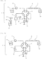
- FIG. 7 shows a schematic view of a flow passage of a liquid chromatograph equipped with the flow passage switching valve 5 of the present embodiment.
- the operation of a liquid chromatograph 1 and the flow passage switching valve 5 will be described with reference to FIGS. 5 and 7 .
- the liquid chromatograph 1 includes a liquid feeding pump 2, a needle 3, a syringe pump 4, the flow passage switching valve 5, a separation column 6, and a detector 7.
- the switching operation of the flow passage switching valve 5 will be described with reference to FIGS. 7A and 7B .
- connection ports of the flow passage switching valve 5 are respectively connected to the liquid feeding pump 2, the separation column 6, the needle 3, the syringe pump 4, a needle port 10, and a waste liquid tank 11.
- an eluent 9 is delivered to the separation column 6, the detector 7, and the waste liquid tank 16 by the liquid feeding pump 2.
- the flow passage switching valve 5 is driven from FIG. 5A to FIG. 5B .
- the syringe pump 4 suctions a sample 8 into the needle 3 and the rotor seal flow passage 242.
- the needle 3 moves to a cleaning port 14, a cleaning liquid 12 is delivered by a cleaning pump 13 at the cleaning port 14, and the sample adhering to an outer periphery of the needle 3 is cleaned by the cleaning port 14.
- the needle 3 holding the sample 8 is connected to the needle port 10.
- the flow passage is switched by rotating the flow passage switching valve 5 by the rotation angle of +60 degrees (60°), which is moved in the opposite direction of the sliding direction, and the flow passage switching valve 5 is as shown in FIG. 5D ( FIGS. 7B and 5D ).
- the liquid feeding pump 2 is driven to deliver the sample 8 in the needle port 10 to the separation column 6, and the sample 8 is separated by the separation column 6 and then detected by the detector 7.
- FIGS. 7A and 7B are repeated for the analysis of another sample.
- FIG. 8 shows a cleaning process of the flow passage switching valve 5 according to the present embodiment.
- FIG. 8A is an exploded view of a cross section of FIG. 5A .
- FIG. 8B is an exploded view of a cross section of FIG. 5B .
- FIG. 8C is an exploded view of a cross section of FIG. 5C .
- FIG. 8D is an exploded view of a cross section of FIG. 5D .
- the flow passage end portions of the rotor seal are arranged on the minus side of the end portions of the stator flow passages and are delivered with liquid or cleaned, the eluent or the cleaning liquid can flow to the flow passage end portions of the rotor seal, the sample remaining at the flow passage end portions of the rotor seal can be cleaned, and the carry over can be reduced.
- FIG. 9 is a top view of a contact surface between a stator and a rotor seal of a flow passage switching valve of a second embodiment according to another embodiment of the invention.
- positions of the stator flow passage end portion 252, the stator flow passage end portion 254, and the stator flow passage end portion 256 are shifted in the sliding direction of the rotor seal flow passages, a distance between centers of the stator flow passage 251 and the stator flow passage 252, a distance between centers of the stator flow passage 253 and the stator flow passage 254, a distance between centers of the stator flow passage 255 and the stator flow passage 256 are longer than a distance between centers of the stator flow passage 251 and the stator flow passage 256, a distance between centers of the stator flow passage 252 and the stator flow passage 253, and a distance between centers of the stator flow passage 254 and the stator flow passage 255.
- the flow passage end portion 2411 at the tip end of the rotor seal in the sliding direction, the flow passage end portion 2421 at the tip end of the rotor seal in the sliding direction, and the flow passage end portion 2431 at the tip end of the rotor seal in the sliding direction are arranged on minus sides in the sliding direction of the stator flow passage end portion 252, the stator flow passage end portion 254, and the stator flow passage end portion 256.
- the switching operation is performed in this arrangement, the abrasion of the stator flow passage end portions and the rotor seal flow passage end portions is reduced, and the life of the valve becomes long.
- stator flow passage 2521 shifted toward an outer peripheral direction of the rotor seal and a stator flow passage 2522 shifted toward a center direction of the rotor seal.
- FIG. 10A is a top view of a contact surface between a stator and a rotor seal of a flow passage switching valve of a third embodiment according to another embodiment of the invention.
- FIG. 10B is a switching operation view of the flow passage switching valve of the present embodiment.
- a long side 2413 of the rotor seal is shorter than the long side of the rotor seal flow passage of the first embodiment described above, and is longer than the center distance between the stator flow passage end portion 251 and the stator flow passage end portion 252.
- a short side 2414 of the rotor seal and a short side 2415 of the rotor seal may not have the same length. In order to perform switching as shown in FIG.
- the number of times of contact between the stator flow passage end portion 251, the stator flow passage end portion 253, and the stator flow passage end portion 255, and the rotor seal flow passage end portion 2411, the rotor seal flow passage end portions 2412 and 2421, the rotor seal flow passage end portion 2422, the rotor seal flow passage end portion 2431, and the rotor seal flow passage end portion 2432 is halved.
- the flow passage end portion 2411 at the tip end in the rotor seal flow passage sliding direction is brought into contact with the stator flow passage end portion 252 and the stator flow passage end portion 253, the flow passage end portion 2412 at the tip end in the rotor seal flow passage sliding direction is brought into contact with the stator flow passage end portion 251 and the stator flow passage end portion 252, the flow passage end portion 2432 at the tip end in the rotor seal flow passage sliding direction is brought into contact with the stator flow passage end portion 253 and the stator flow passage end portion 254, the flow passage end portion 2431 at the tip end in the rotor seal flow passage sliding direction is brought into contact with the stator flow passage end portion 254 and the stator flow passage end portion 255, the flow passage end portion 2422 at the tip end in the rotor seal flow passage sliding direction is brought into contact with the stator flow passage end portion 255 and the stator flow passage end portion 256, and the flow passage end portion 2421 at the tip end in the rotor seal flow passage sliding direction is brought into contact with
- the stator flow passage end portion 252 is brought into contact with the flow passage end portion 2411 at the tip end in the rotor seal flow passage sliding direction and the flow passage end portion 2412 at the tip end in the rotor seal flow passage sliding direction, the stator flow passage end portion 254 is brought into contact with the flow passage end portion 2431 at the tip end in the rotor seal flow passage sliding direction and the flow passage end portion 2432 at the tip end in the rotor seal flow passage sliding direction, and the stator flow passage end portion 256 is brought into contact with the flow passage end portion 2421 at the tip end in the rotor seal flow passage sliding direction and the flow passage end portion 2421 at the tip end in the rotor seal flow passage sliding direction.
- the number of portions to be scraped is increased as compared with the related art, the entire stator flow passage end portions 251 to 256 are contacted without biasing, the portions to be scraped are dispersed, and the number of contact is reduced. Therefore, the amount of the abrasion due to contact with the flow passage end portions on the contact surface between the stator and the rotor seal is reduced. As a result, the life is further longer.
- the present embodiment describes an aspect that distances between the centers of the stator flow passages arranged adjacent to each other on a circumference is substantially the same.
- the invention is not limited thereto, and the distances between the centers of the stator flow passages arranged adjacent to each other on the circumference may be different from each other, that is, there are a plurality of distances between the centers of a pair of adjacent stator flow passages. In this case, one having the longest distance between the centers may be used as a reference.
- the long side of the rotor seal flow passage may be longer than those having the longest distance between the centers of the stator flow passages, and the flow passage end portions at both ends of the rotor seal flow passage may be arranged in the direction opposite to the sliding direction of the stator flow passage end portions.
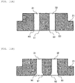
- FIG. 11A is a cross-sectional view of the stator of the flow passage switching valve according to the first embodiment described above.
- FIG. 11B is a cross-sectional view of a stator of a flow passage switching valve of a fourth embodiment according to another embodiment of the invention.
- flow passage end portions 80 to 83 of an opening of a stator flow passage that comes into contact with the rotor seal of FIG. 11A may be chamfered like flow passage end portions 90 to 93 of FIG. 11B .
- stress concentration at the stator flow passage end portions can be reduced, the abrasion of the stator flow passage end portions and the rotor seal flow passage end portions is small, and the life is long.
Landscapes
- Engineering & Computer Science (AREA)
- General Engineering & Computer Science (AREA)
- Mechanical Engineering (AREA)
- Physics & Mathematics (AREA)
- Health & Medical Sciences (AREA)
- Life Sciences & Earth Sciences (AREA)
- Chemical & Material Sciences (AREA)
- Analytical Chemistry (AREA)
- Biochemistry (AREA)
- General Health & Medical Sciences (AREA)
- General Physics & Mathematics (AREA)
- Immunology (AREA)
- Pathology (AREA)
- Multiple-Way Valves (AREA)
Applications Claiming Priority (2)
| Application Number | Priority Date | Filing Date | Title |
|---|---|---|---|
| JP2019041379A JP7133499B2 (ja) | 2019-03-07 | 2019-03-07 | 流路切替バルブ及びそれを有する液体クロマトグラフ |
| PCT/JP2019/046960 WO2020179157A1 (ja) | 2019-03-07 | 2019-12-02 | 流路切替バルブ及びそれを有する液体クロマトグラフ |
Publications (3)
| Publication Number | Publication Date |
|---|---|
| EP3936746A1 true EP3936746A1 (de) | 2022-01-12 |
| EP3936746A4 EP3936746A4 (de) | 2022-12-14 |
| EP3936746B1 EP3936746B1 (de) | 2024-02-28 |
Family
ID=72338486
Family Applications (1)
| Application Number | Title | Priority Date | Filing Date |
|---|---|---|---|
| EP19918087.8A Active EP3936746B1 (de) | 2019-03-07 | 2019-12-02 | Verfahren zum betrieb eines durchflussschaltventils und eines flüssigkeitschromatographs mit einem solchen ventil |
Country Status (5)
| Country | Link |
|---|---|
| US (1) | US12158452B2 (de) |
| EP (1) | EP3936746B1 (de) |
| JP (1) | JP7133499B2 (de) |
| CN (1) | CN113396299B (de) |
| WO (1) | WO2020179157A1 (de) |
Families Citing this family (5)
| Publication number | Priority date | Publication date | Assignee | Title |
|---|---|---|---|---|
| JP7303723B2 (ja) * | 2019-10-17 | 2023-07-05 | 株式会社日立ハイテク | 流路切替バルブシステムおよび液体クロマトグラフ |
| JP7474691B2 (ja) * | 2020-12-15 | 2024-04-25 | 株式会社日立ハイテク | 流路切替バルブおよび液体クロマトグラフ |
| TWI806478B (zh) * | 2022-03-08 | 2023-06-21 | 國立清華大學 | 自動化連續純化系統 |
| CN115574119B (zh) * | 2022-09-22 | 2026-03-31 | 苏州赛谱仪器有限公司 | 一种多位置选择阀 |
| JP2024073868A (ja) * | 2022-11-18 | 2024-05-30 | 愛三工業株式会社 | 流路切替装置 |
Family Cites Families (7)
| Publication number | Priority date | Publication date | Assignee | Title |
|---|---|---|---|---|
| JP3354783B2 (ja) * | 1996-03-27 | 2002-12-09 | 東芝キヤリア株式会社 | 流体圧縮機およびヒートポンプ式冷凍サイクル |
| US6910394B2 (en) | 2001-05-31 | 2005-06-28 | Wayne A. Kriel | Chromatograph valve and method of use |
| US8047060B2 (en) | 2005-01-31 | 2011-11-01 | Waters Technologies Corporation | Method and apparatus for sample injection in liquid chromatography |
| JP5573838B2 (ja) | 2009-06-29 | 2014-08-20 | 株式会社島津製作所 | 液体クロマトグラフ装置 |
| WO2011001460A1 (ja) | 2009-06-29 | 2011-01-06 | 株式会社島津製作所 | 流路切換バルブ |
| JP2014095613A (ja) | 2012-11-09 | 2014-05-22 | Hitachi High-Technologies Corp | 液体試料分析装置および液体試料導入装置 |
| CN113271043B (zh) * | 2021-05-26 | 2022-12-23 | 永大电梯设备(中国)有限公司 | 旋转变压器转子同永磁同步电机转子角度偏差校正方法 |
-
2019
- 2019-03-07 JP JP2019041379A patent/JP7133499B2/ja active Active
- 2019-12-02 EP EP19918087.8A patent/EP3936746B1/de active Active
- 2019-12-02 US US17/427,757 patent/US12158452B2/en active Active
- 2019-12-02 WO PCT/JP2019/046960 patent/WO2020179157A1/ja not_active Ceased
- 2019-12-02 CN CN201980091332.6A patent/CN113396299B/zh active Active
Also Published As
| Publication number | Publication date |
|---|---|
| US20210382018A1 (en) | 2021-12-09 |
| EP3936746B1 (de) | 2024-02-28 |
| CN113396299A (zh) | 2021-09-14 |
| WO2020179157A1 (ja) | 2020-09-10 |
| JP7133499B2 (ja) | 2022-09-08 |
| EP3936746A4 (de) | 2022-12-14 |
| JP2020144027A (ja) | 2020-09-10 |
| CN113396299B (zh) | 2023-07-28 |
| US12158452B2 (en) | 2024-12-03 |
Similar Documents
| Publication | Publication Date | Title |
|---|---|---|
| US12158452B2 (en) | Flow passage switching valve and liquid chromatograph having the same | |
| CN102472400B (zh) | 液相色谱仪系统 | |
| US8322374B2 (en) | Channel switching valve | |
| CN107407664B (zh) | 旋转阀和色谱系统 | |
| US9188238B2 (en) | Flow channel switching valve | |
| EP3779252A1 (de) | Mehrwegeventil für wasserqualitätsanalysator | |
| JP5790776B2 (ja) | 流路切換バルブ | |
| US20260079133A1 (en) | Injection valve | |
| EP4047362A1 (de) | Durchflusswegschaltventil, durchflusswegschaltventilsystem und flüssigkeitschromatograf | |
| US20140191146A1 (en) | Rotary Shear Valve with a Two-pin Drive Shaft for Liquid Chromatography Applications | |
| CN114518426B (zh) | 一种进样阀 | |
| US9657852B2 (en) | Flow through isolation valve for high pressure fluids | |
| CN116480811A (zh) | 用于样品注入的旋转阀和进样系统 | |
| US20070137713A1 (en) | Combination flow through injection and isolation valve for high pressure fluids | |
| JP5573838B2 (ja) | 液体クロマトグラフ装置 | |
| CN222185877U (zh) | 一种拼装式六通阀定子结构 | |
| CN120426412A (zh) | 一种电动阀 |
Legal Events
| Date | Code | Title | Description |
|---|---|---|---|
| STAA | Information on the status of an ep patent application or granted ep patent |
Free format text: STATUS: THE INTERNATIONAL PUBLICATION HAS BEEN MADE |
|
| PUAI | Public reference made under article 153(3) epc to a published international application that has entered the european phase |
Free format text: ORIGINAL CODE: 0009012 |
|
| STAA | Information on the status of an ep patent application or granted ep patent |
Free format text: STATUS: REQUEST FOR EXAMINATION WAS MADE |
|
| 17P | Request for examination filed |
Effective date: 20211007 |
|
| AK | Designated contracting states |
Kind code of ref document: A1 Designated state(s): AL AT BE BG CH CY CZ DE DK EE ES FI FR GB GR HR HU IE IS IT LI LT LU LV MC MK MT NL NO PL PT RO RS SE SI SK SM TR |
|
| DAV | Request for validation of the european patent (deleted) | ||
| DAX | Request for extension of the european patent (deleted) | ||
| A4 | Supplementary search report drawn up and despatched |
Effective date: 20221114 |
|
| RIC1 | Information provided on ipc code assigned before grant |
Ipc: F16K 37/00 20060101ALI20221108BHEP Ipc: G01N 30/26 20060101ALI20221108BHEP Ipc: F16K 11/074 20060101AFI20221108BHEP |
|
| STAA | Information on the status of an ep patent application or granted ep patent |
Free format text: STATUS: EXAMINATION IS IN PROGRESS |
|
| 17Q | First examination report despatched |
Effective date: 20230411 |
|
| GRAP | Despatch of communication of intention to grant a patent |
Free format text: ORIGINAL CODE: EPIDOSNIGR1 |
|
| STAA | Information on the status of an ep patent application or granted ep patent |
Free format text: STATUS: GRANT OF PATENT IS INTENDED |
|
| INTG | Intention to grant announced |
Effective date: 20231113 |
|
| GRAS | Grant fee paid |
Free format text: ORIGINAL CODE: EPIDOSNIGR3 |
|
| GRAA | (expected) grant |
Free format text: ORIGINAL CODE: 0009210 |
|
| STAA | Information on the status of an ep patent application or granted ep patent |
Free format text: STATUS: THE PATENT HAS BEEN GRANTED |
|
| AK | Designated contracting states |
Kind code of ref document: B1 Designated state(s): AL AT BE BG CH CY CZ DE DK EE ES FI FR GB GR HR HU IE IS IT LI LT LU LV MC MK MT NL NO PL PT RO RS SE SI SK SM TR |
|
| REG | Reference to a national code |
Ref country code: GB Ref legal event code: FG4D |
|
| REG | Reference to a national code |
Ref country code: CH Ref legal event code: EP |
|
| REG | Reference to a national code |
Ref country code: DE Ref legal event code: R096 Ref document number: 602019047563 Country of ref document: DE |
|
| REG | Reference to a national code |
Ref country code: IE Ref legal event code: FG4D |
|
| REG | Reference to a national code |
Ref country code: LT Ref legal event code: MG9D |
|
| PG25 | Lapsed in a contracting state [announced via postgrant information from national office to epo] |
Ref country code: IS Free format text: LAPSE BECAUSE OF FAILURE TO SUBMIT A TRANSLATION OF THE DESCRIPTION OR TO PAY THE FEE WITHIN THE PRESCRIBED TIME-LIMIT Effective date: 20240628 |
|
| REG | Reference to a national code |
Ref country code: NL Ref legal event code: MP Effective date: 20240228 |
|
| PG25 | Lapsed in a contracting state [announced via postgrant information from national office to epo] |
Ref country code: LT Free format text: LAPSE BECAUSE OF FAILURE TO SUBMIT A TRANSLATION OF THE DESCRIPTION OR TO PAY THE FEE WITHIN THE PRESCRIBED TIME-LIMIT Effective date: 20240228 |
|
| PG25 | Lapsed in a contracting state [announced via postgrant information from national office to epo] |
Ref country code: GR Free format text: LAPSE BECAUSE OF FAILURE TO SUBMIT A TRANSLATION OF THE DESCRIPTION OR TO PAY THE FEE WITHIN THE PRESCRIBED TIME-LIMIT Effective date: 20240529 |
|
| PG25 | Lapsed in a contracting state [announced via postgrant information from national office to epo] |
Ref country code: HR Free format text: LAPSE BECAUSE OF FAILURE TO SUBMIT A TRANSLATION OF THE DESCRIPTION OR TO PAY THE FEE WITHIN THE PRESCRIBED TIME-LIMIT Effective date: 20240228 Ref country code: RS Free format text: LAPSE BECAUSE OF FAILURE TO SUBMIT A TRANSLATION OF THE DESCRIPTION OR TO PAY THE FEE WITHIN THE PRESCRIBED TIME-LIMIT Effective date: 20240528 Ref country code: NL Free format text: LAPSE BECAUSE OF FAILURE TO SUBMIT A TRANSLATION OF THE DESCRIPTION OR TO PAY THE FEE WITHIN THE PRESCRIBED TIME-LIMIT Effective date: 20240228 |
|
| PG25 | Lapsed in a contracting state [announced via postgrant information from national office to epo] |
Ref country code: ES Free format text: LAPSE BECAUSE OF FAILURE TO SUBMIT A TRANSLATION OF THE DESCRIPTION OR TO PAY THE FEE WITHIN THE PRESCRIBED TIME-LIMIT Effective date: 20240228 |
|
| PG25 | Lapsed in a contracting state [announced via postgrant information from national office to epo] |
Ref country code: RS Free format text: LAPSE BECAUSE OF FAILURE TO SUBMIT A TRANSLATION OF THE DESCRIPTION OR TO PAY THE FEE WITHIN THE PRESCRIBED TIME-LIMIT Effective date: 20240528 Ref country code: NO Free format text: LAPSE BECAUSE OF FAILURE TO SUBMIT A TRANSLATION OF THE DESCRIPTION OR TO PAY THE FEE WITHIN THE PRESCRIBED TIME-LIMIT Effective date: 20240528 Ref country code: NL Free format text: LAPSE BECAUSE OF FAILURE TO SUBMIT A TRANSLATION OF THE DESCRIPTION OR TO PAY THE FEE WITHIN THE PRESCRIBED TIME-LIMIT Effective date: 20240228 Ref country code: LT Free format text: LAPSE BECAUSE OF FAILURE TO SUBMIT A TRANSLATION OF THE DESCRIPTION OR TO PAY THE FEE WITHIN THE PRESCRIBED TIME-LIMIT Effective date: 20240228 Ref country code: IS Free format text: LAPSE BECAUSE OF FAILURE TO SUBMIT A TRANSLATION OF THE DESCRIPTION OR TO PAY THE FEE WITHIN THE PRESCRIBED TIME-LIMIT Effective date: 20240628 Ref country code: HR Free format text: LAPSE BECAUSE OF FAILURE TO SUBMIT A TRANSLATION OF THE DESCRIPTION OR TO PAY THE FEE WITHIN THE PRESCRIBED TIME-LIMIT Effective date: 20240228 Ref country code: GR Free format text: LAPSE BECAUSE OF FAILURE TO SUBMIT A TRANSLATION OF THE DESCRIPTION OR TO PAY THE FEE WITHIN THE PRESCRIBED TIME-LIMIT Effective date: 20240529 Ref country code: FI Free format text: LAPSE BECAUSE OF FAILURE TO SUBMIT A TRANSLATION OF THE DESCRIPTION OR TO PAY THE FEE WITHIN THE PRESCRIBED TIME-LIMIT Effective date: 20240228 Ref country code: ES Free format text: LAPSE BECAUSE OF FAILURE TO SUBMIT A TRANSLATION OF THE DESCRIPTION OR TO PAY THE FEE WITHIN THE PRESCRIBED TIME-LIMIT Effective date: 20240228 Ref country code: BG Free format text: LAPSE BECAUSE OF FAILURE TO SUBMIT A TRANSLATION OF THE DESCRIPTION OR TO PAY THE FEE WITHIN THE PRESCRIBED TIME-LIMIT Effective date: 20240228 |
|
| PG25 | Lapsed in a contracting state [announced via postgrant information from national office to epo] |
Ref country code: PT Free format text: LAPSE BECAUSE OF FAILURE TO SUBMIT A TRANSLATION OF THE DESCRIPTION OR TO PAY THE FEE WITHIN THE PRESCRIBED TIME-LIMIT Effective date: 20240628 Ref country code: PL Free format text: LAPSE BECAUSE OF FAILURE TO SUBMIT A TRANSLATION OF THE DESCRIPTION OR TO PAY THE FEE WITHIN THE PRESCRIBED TIME-LIMIT Effective date: 20240228 |
|
| REG | Reference to a national code |
Ref country code: AT Ref legal event code: MK05 Ref document number: 1661534 Country of ref document: AT Kind code of ref document: T Effective date: 20240228 |
|
| PG25 | Lapsed in a contracting state [announced via postgrant information from national office to epo] |
Ref country code: SE Free format text: LAPSE BECAUSE OF FAILURE TO SUBMIT A TRANSLATION OF THE DESCRIPTION OR TO PAY THE FEE WITHIN THE PRESCRIBED TIME-LIMIT Effective date: 20240228 Ref country code: PT Free format text: LAPSE BECAUSE OF FAILURE TO SUBMIT A TRANSLATION OF THE DESCRIPTION OR TO PAY THE FEE WITHIN THE PRESCRIBED TIME-LIMIT Effective date: 20240628 Ref country code: PL Free format text: LAPSE BECAUSE OF FAILURE TO SUBMIT A TRANSLATION OF THE DESCRIPTION OR TO PAY THE FEE WITHIN THE PRESCRIBED TIME-LIMIT Effective date: 20240228 Ref country code: LV Free format text: LAPSE BECAUSE OF FAILURE TO SUBMIT A TRANSLATION OF THE DESCRIPTION OR TO PAY THE FEE WITHIN THE PRESCRIBED TIME-LIMIT Effective date: 20240228 |
|
| PG25 | Lapsed in a contracting state [announced via postgrant information from national office to epo] |
Ref country code: DK Free format text: LAPSE BECAUSE OF FAILURE TO SUBMIT A TRANSLATION OF THE DESCRIPTION OR TO PAY THE FEE WITHIN THE PRESCRIBED TIME-LIMIT Effective date: 20240228 |
|
| PG25 | Lapsed in a contracting state [announced via postgrant information from national office to epo] |
Ref country code: SM Free format text: LAPSE BECAUSE OF FAILURE TO SUBMIT A TRANSLATION OF THE DESCRIPTION OR TO PAY THE FEE WITHIN THE PRESCRIBED TIME-LIMIT Effective date: 20240228 |
|
| PG25 | Lapsed in a contracting state [announced via postgrant information from national office to epo] |
Ref country code: CZ Free format text: LAPSE BECAUSE OF FAILURE TO SUBMIT A TRANSLATION OF THE DESCRIPTION OR TO PAY THE FEE WITHIN THE PRESCRIBED TIME-LIMIT Effective date: 20240228 Ref country code: EE Free format text: LAPSE BECAUSE OF FAILURE TO SUBMIT A TRANSLATION OF THE DESCRIPTION OR TO PAY THE FEE WITHIN THE PRESCRIBED TIME-LIMIT Effective date: 20240228 |
|
| PG25 | Lapsed in a contracting state [announced via postgrant information from national office to epo] |
Ref country code: AT Free format text: LAPSE BECAUSE OF FAILURE TO SUBMIT A TRANSLATION OF THE DESCRIPTION OR TO PAY THE FEE WITHIN THE PRESCRIBED TIME-LIMIT Effective date: 20240228 |
|
| PG25 | Lapsed in a contracting state [announced via postgrant information from national office to epo] |
Ref country code: SK Free format text: LAPSE BECAUSE OF FAILURE TO SUBMIT A TRANSLATION OF THE DESCRIPTION OR TO PAY THE FEE WITHIN THE PRESCRIBED TIME-LIMIT Effective date: 20240228 |
|
| PG25 | Lapsed in a contracting state [announced via postgrant information from national office to epo] |
Ref country code: SM Free format text: LAPSE BECAUSE OF FAILURE TO SUBMIT A TRANSLATION OF THE DESCRIPTION OR TO PAY THE FEE WITHIN THE PRESCRIBED TIME-LIMIT Effective date: 20240228 Ref country code: SK Free format text: LAPSE BECAUSE OF FAILURE TO SUBMIT A TRANSLATION OF THE DESCRIPTION OR TO PAY THE FEE WITHIN THE PRESCRIBED TIME-LIMIT Effective date: 20240228 Ref country code: RO Free format text: LAPSE BECAUSE OF FAILURE TO SUBMIT A TRANSLATION OF THE DESCRIPTION OR TO PAY THE FEE WITHIN THE PRESCRIBED TIME-LIMIT Effective date: 20240228 Ref country code: EE Free format text: LAPSE BECAUSE OF FAILURE TO SUBMIT A TRANSLATION OF THE DESCRIPTION OR TO PAY THE FEE WITHIN THE PRESCRIBED TIME-LIMIT Effective date: 20240228 Ref country code: DK Free format text: LAPSE BECAUSE OF FAILURE TO SUBMIT A TRANSLATION OF THE DESCRIPTION OR TO PAY THE FEE WITHIN THE PRESCRIBED TIME-LIMIT Effective date: 20240228 Ref country code: CZ Free format text: LAPSE BECAUSE OF FAILURE TO SUBMIT A TRANSLATION OF THE DESCRIPTION OR TO PAY THE FEE WITHIN THE PRESCRIBED TIME-LIMIT Effective date: 20240228 Ref country code: AT Free format text: LAPSE BECAUSE OF FAILURE TO SUBMIT A TRANSLATION OF THE DESCRIPTION OR TO PAY THE FEE WITHIN THE PRESCRIBED TIME-LIMIT Effective date: 20240228 |
|
| REG | Reference to a national code |
Ref country code: DE Ref legal event code: R097 Ref document number: 602019047563 Country of ref document: DE |
|
| PG25 | Lapsed in a contracting state [announced via postgrant information from national office to epo] |
Ref country code: IT Free format text: LAPSE BECAUSE OF FAILURE TO SUBMIT A TRANSLATION OF THE DESCRIPTION OR TO PAY THE FEE WITHIN THE PRESCRIBED TIME-LIMIT Effective date: 20240228 |
|
| PG25 | Lapsed in a contracting state [announced via postgrant information from national office to epo] |
Ref country code: IT Free format text: LAPSE BECAUSE OF FAILURE TO SUBMIT A TRANSLATION OF THE DESCRIPTION OR TO PAY THE FEE WITHIN THE PRESCRIBED TIME-LIMIT Effective date: 20240228 |
|
| PLBE | No opposition filed within time limit |
Free format text: ORIGINAL CODE: 0009261 |
|
| STAA | Information on the status of an ep patent application or granted ep patent |
Free format text: STATUS: NO OPPOSITION FILED WITHIN TIME LIMIT |
|
| 26N | No opposition filed |
Effective date: 20241129 |
|
| PG25 | Lapsed in a contracting state [announced via postgrant information from national office to epo] |
Ref country code: SI Free format text: LAPSE BECAUSE OF FAILURE TO SUBMIT A TRANSLATION OF THE DESCRIPTION OR TO PAY THE FEE WITHIN THE PRESCRIBED TIME-LIMIT Effective date: 20240228 |
|
| PG25 | Lapsed in a contracting state [announced via postgrant information from national office to epo] |
Ref country code: MC Free format text: LAPSE BECAUSE OF FAILURE TO SUBMIT A TRANSLATION OF THE DESCRIPTION OR TO PAY THE FEE WITHIN THE PRESCRIBED TIME-LIMIT Effective date: 20240228 |
|
| REG | Reference to a national code |
Ref country code: CH Ref legal event code: PL |
|
| PG25 | Lapsed in a contracting state [announced via postgrant information from national office to epo] |
Ref country code: LU Free format text: LAPSE BECAUSE OF NON-PAYMENT OF DUE FEES Effective date: 20241202 |
|
| REG | Reference to a national code |
Ref country code: BE Ref legal event code: MM Effective date: 20241231 |
|
| PG25 | Lapsed in a contracting state [announced via postgrant information from national office to epo] |
Ref country code: BE Free format text: LAPSE BECAUSE OF NON-PAYMENT OF DUE FEES Effective date: 20241231 |
|
| PG25 | Lapsed in a contracting state [announced via postgrant information from national office to epo] |
Ref country code: FR Free format text: LAPSE BECAUSE OF NON-PAYMENT OF DUE FEES Effective date: 20241231 |
|
| PG25 | Lapsed in a contracting state [announced via postgrant information from national office to epo] |
Ref country code: CH Free format text: LAPSE BECAUSE OF NON-PAYMENT OF DUE FEES Effective date: 20241231 |
|
| PG25 | Lapsed in a contracting state [announced via postgrant information from national office to epo] |
Ref country code: IE Free format text: LAPSE BECAUSE OF NON-PAYMENT OF DUE FEES Effective date: 20241202 |
|
| PGFP | Annual fee paid to national office [announced via postgrant information from national office to epo] |
Ref country code: GB Payment date: 20251218 Year of fee payment: 7 |
|
| PG25 | Lapsed in a contracting state [announced via postgrant information from national office to epo] |
Ref country code: CY Free format text: LAPSE BECAUSE OF FAILURE TO SUBMIT A TRANSLATION OF THE DESCRIPTION OR TO PAY THE FEE WITHIN THE PRESCRIBED TIME-LIMIT; INVALID AB INITIO Effective date: 20191202 |
|
| PGFP | Annual fee paid to national office [announced via postgrant information from national office to epo] |
Ref country code: DE Payment date: 20251231 Year of fee payment: 7 |