EP4047362A1 - Durchflusswegschaltventil, durchflusswegschaltventilsystem und flüssigkeitschromatograf - Google Patents
Durchflusswegschaltventil, durchflusswegschaltventilsystem und flüssigkeitschromatograf Download PDFInfo
- Publication number
- EP4047362A1 EP4047362A1 EP20877089.1A EP20877089A EP4047362A1 EP 4047362 A1 EP4047362 A1 EP 4047362A1 EP 20877089 A EP20877089 A EP 20877089A EP 4047362 A1 EP4047362 A1 EP 4047362A1
- Authority
- EP
- European Patent Office
- Prior art keywords
- flow passage
- rotor
- stator
- seal
- switching valve
- Prior art date
- Legal status (The legal status is an assumption and is not a legal conclusion. Google has not performed a legal analysis and makes no representation as to the accuracy of the status listed.)
- Pending
Links
Images




Classifications
-
- F—MECHANICAL ENGINEERING; LIGHTING; HEATING; WEAPONS; BLASTING
- F16—ENGINEERING ELEMENTS AND UNITS; GENERAL MEASURES FOR PRODUCING AND MAINTAINING EFFECTIVE FUNCTIONING OF MACHINES OR INSTALLATIONS; THERMAL INSULATION IN GENERAL
- F16K—VALVES; TAPS; COCKS; ACTUATING-FLOATS; DEVICES FOR VENTING OR AERATING
- F16K11/00—Multiple-way valves, e.g. mixing valves; Pipe fittings incorporating such valves
- F16K11/02—Multiple-way valves, e.g. mixing valves; Pipe fittings incorporating such valves with all movable sealing faces moving as one unit
- F16K11/06—Multiple-way valves, e.g. mixing valves; Pipe fittings incorporating such valves with all movable sealing faces moving as one unit comprising only sliding valves, i.e. sliding closure elements
- F16K11/072—Multiple-way valves, e.g. mixing valves; Pipe fittings incorporating such valves with all movable sealing faces moving as one unit comprising only sliding valves, i.e. sliding closure elements with pivoted closure members
- F16K11/074—Multiple-way valves, e.g. mixing valves; Pipe fittings incorporating such valves with all movable sealing faces moving as one unit comprising only sliding valves, i.e. sliding closure elements with pivoted closure members with flat sealing faces
-
- G—PHYSICS
- G01—MEASURING; TESTING
- G01N—INVESTIGATING OR ANALYSING MATERIALS BY DETERMINING THEIR CHEMICAL OR PHYSICAL PROPERTIES
- G01N30/00—Investigating or analysing materials by separation into components using adsorption, absorption or similar phenomena or using ion-exchange, e.g. chromatography or field flow fractionation
- G01N30/02—Column chromatography
- G01N30/26—Conditioning of the fluid carrier; Flow patterns
- G01N30/38—Flow patterns
-
- F—MECHANICAL ENGINEERING; LIGHTING; HEATING; WEAPONS; BLASTING
- F16—ENGINEERING ELEMENTS AND UNITS; GENERAL MEASURES FOR PRODUCING AND MAINTAINING EFFECTIVE FUNCTIONING OF MACHINES OR INSTALLATIONS; THERMAL INSULATION IN GENERAL
- F16K—VALVES; TAPS; COCKS; ACTUATING-FLOATS; DEVICES FOR VENTING OR AERATING
- F16K11/00—Multiple-way valves, e.g. mixing valves; Pipe fittings incorporating such valves
- F16K11/02—Multiple-way valves, e.g. mixing valves; Pipe fittings incorporating such valves with all movable sealing faces moving as one unit
- F16K11/06—Multiple-way valves, e.g. mixing valves; Pipe fittings incorporating such valves with all movable sealing faces moving as one unit comprising only sliding valves, i.e. sliding closure elements
- F16K11/072—Multiple-way valves, e.g. mixing valves; Pipe fittings incorporating such valves with all movable sealing faces moving as one unit comprising only sliding valves, i.e. sliding closure elements with pivoted closure members
- F16K11/074—Multiple-way valves, e.g. mixing valves; Pipe fittings incorporating such valves with all movable sealing faces moving as one unit comprising only sliding valves, i.e. sliding closure elements with pivoted closure members with flat sealing faces
- F16K11/0743—Multiple-way valves, e.g. mixing valves; Pipe fittings incorporating such valves with all movable sealing faces moving as one unit comprising only sliding valves, i.e. sliding closure elements with pivoted closure members with flat sealing faces with both the supply and the discharge passages being on one side of the closure plates
-
- F—MECHANICAL ENGINEERING; LIGHTING; HEATING; WEAPONS; BLASTING
- F16—ENGINEERING ELEMENTS AND UNITS; GENERAL MEASURES FOR PRODUCING AND MAINTAINING EFFECTIVE FUNCTIONING OF MACHINES OR INSTALLATIONS; THERMAL INSULATION IN GENERAL
- F16K—VALVES; TAPS; COCKS; ACTUATING-FLOATS; DEVICES FOR VENTING OR AERATING
- F16K37/00—Special means in or on valves or other cut-off apparatus for indicating or recording operation thereof, or for enabling an alarm to be given
- F16K37/0025—Electrical or magnetic means
- F16K37/0041—Electrical or magnetic means for measuring valve parameters
-
- F—MECHANICAL ENGINEERING; LIGHTING; HEATING; WEAPONS; BLASTING
- F16—ENGINEERING ELEMENTS AND UNITS; GENERAL MEASURES FOR PRODUCING AND MAINTAINING EFFECTIVE FUNCTIONING OF MACHINES OR INSTALLATIONS; THERMAL INSULATION IN GENERAL
- F16K—VALVES; TAPS; COCKS; ACTUATING-FLOATS; DEVICES FOR VENTING OR AERATING
- F16K37/00—Special means in or on valves or other cut-off apparatus for indicating or recording operation thereof, or for enabling an alarm to be given
- F16K37/0025—Electrical or magnetic means
- F16K37/005—Electrical or magnetic means for measuring fluid parameters
-
- G—PHYSICS
- G01—MEASURING; TESTING
- G01N—INVESTIGATING OR ANALYSING MATERIALS BY DETERMINING THEIR CHEMICAL OR PHYSICAL PROPERTIES
- G01N30/00—Investigating or analysing materials by separation into components using adsorption, absorption or similar phenomena or using ion-exchange, e.g. chromatography or field flow fractionation
- G01N30/02—Column chromatography
- G01N30/04—Preparation or injection of sample to be analysed
- G01N30/16—Injection
- G01N30/20—Injection using a sampling valve
-
- G—PHYSICS
- G01—MEASURING; TESTING
- G01N—INVESTIGATING OR ANALYSING MATERIALS BY DETERMINING THEIR CHEMICAL OR PHYSICAL PROPERTIES
- G01N30/00—Investigating or analysing materials by separation into components using adsorption, absorption or similar phenomena or using ion-exchange, e.g. chromatography or field flow fractionation
- G01N30/02—Column chromatography
- G01N30/26—Conditioning of the fluid carrier; Flow patterns
-
- G—PHYSICS
- G01—MEASURING; TESTING
- G01N—INVESTIGATING OR ANALYSING MATERIALS BY DETERMINING THEIR CHEMICAL OR PHYSICAL PROPERTIES
- G01N30/00—Investigating or analysing materials by separation into components using adsorption, absorption or similar phenomena or using ion-exchange, e.g. chromatography or field flow fractionation
- G01N30/02—Column chromatography
- G01N30/04—Preparation or injection of sample to be analysed
- G01N30/16—Injection
- G01N30/20—Injection using a sampling valve
- G01N2030/201—Injection using a sampling valve multiport valves, i.e. having more than two ports
-
- G—PHYSICS
- G01—MEASURING; TESTING
- G01N—INVESTIGATING OR ANALYSING MATERIALS BY DETERMINING THEIR CHEMICAL OR PHYSICAL PROPERTIES
- G01N30/00—Investigating or analysing materials by separation into components using adsorption, absorption or similar phenomena or using ion-exchange, e.g. chromatography or field flow fractionation
- G01N30/02—Column chromatography
- G01N30/04—Preparation or injection of sample to be analysed
- G01N30/16—Injection
- G01N30/20—Injection using a sampling valve
- G01N2030/202—Injection using a sampling valve rotary valves
-
- G—PHYSICS
- G01—MEASURING; TESTING
- G01N—INVESTIGATING OR ANALYSING MATERIALS BY DETERMINING THEIR CHEMICAL OR PHYSICAL PROPERTIES
- G01N30/00—Investigating or analysing materials by separation into components using adsorption, absorption or similar phenomena or using ion-exchange, e.g. chromatography or field flow fractionation
- G01N30/02—Column chromatography
- G01N30/26—Conditioning of the fluid carrier; Flow patterns
- G01N30/38—Flow patterns
- G01N2030/382—Flow patterns flow switching in a single column
- G01N2030/385—Flow patterns flow switching in a single column by switching valves
Definitions
- the present invention relates to a flow passage switching valve, a flow passage switching valve system, and a liquid chromatograph.
- An analyzing device such as a liquid chromatograph has a flow passage switching valve for switching between many flow passages.
- the flow passage switching valve is configured of a stator for pipe coupling, a rotor seal, a rotor to rotate the rotor seal, and a housing to hold such components.
- the rotor seal is pressed to the stator by a spring or the like to maintain fluid-tightness between flow passages formed in the rotor seal and flow passages formed in the stator.
- the rotor seal is fixed to the rotor by a pin and rotated along with rotation of the rotor by a motor, so that each flow passage in the rotor seal is switched with respect to the respective flow passages in the stator.
- the rotor seal of the flow passage switching valve slidably rotates while being pressed to the stator.
- a sliding surface between the rotor seal and the stator is abraded during rotation of the rotor seal, and when the amount of abrasion exceeds a certain value, liquid leakage occurs, which impairs the function of the valve.
- Patent Literature 1 discloses a flow passage switching valve having a structure that suppresses such abrasion of the sliding surface.
- the flow passage switching valve of Patent Literature 1 is characterized by including a stator, and a rotor that has a surface to be in contact with one surface of the stator and a surface to be in contact with the one surface of the stator and rotates while sliding on the contact surface, where the stator has a plurality of liquid circulation ports opened to the contact surface, the rotor has a plurality of flow passage grooves to connect the liquid circulation ports together, and a rotor seal has a pressure release groove.
- the rotor seal is extended concentrically on the circumference along a sufficiently long pressure release area, which sufficiently reduces a flow rate of a fluid generated when the pressure release groove overlaps a port opening of the stator, and in turn avoids damage on the flow passages in the stator and the rotor seal. It is therefore possible to prevent the contact surface from being scraped by an edge of the port opening during rotor rotation, and thus prevent the operating life from being reduced by abrasion or damage of the flow passage.
- Patent Literature 2 describes a configuration of a flow passage switching valve capable of switching between a first state and a second state.
- An object of the present invention which is made in light of such circumstances, is to provide a flow passage switching valve having a long operating life by dispersing an area abraded on a sliding surface between a stator and a rotor to the whole sliding surface.
- One example of a flow passage switching valve according to the present invention includes a stator and a rotor configured to be rotatable with respect to the stator,
- an area to be abraded on a sliding surface between a stator and a rotor is dispersed, making it possible to prolong the operating life of a flow passage switching valve.
- Figs. 1A to 1D illustrate an exemplary configuration of a flow passage switching valve 5 of the invention.
- Fig. 1A shows a cross-sectional view as a plane parallel to an axis (for example, rotational axis, the same shall apply hereinafter) of the flow passage switching valve 5.
- Fig. 1A is taken along the dashed line in Fig. 1D.
- Fig. 1B shows a top view of a rotor seal 22
- Fig. 1C shows a top view of a portion of a stator main body 21 in contact with the rotor seal 22.
- the surface of the stator main body 21 shown in Fig. 1C is actually faces downward and cannot be seen from the above, Fig.
- FIG. 1C shows a shape of the surface as viewed from the above for ease in understanding of overlapping with the rotor seal 22.
- Fig. 1D shows a positional relationship between flow passages of the stator main body 21 and the rotor seal 22 when a contact surface of the stator main body 21 is set to overlap a contact surface of the rotor seal 22.
- the flow passage switching valve 5 includes the stator and the rotor.
- the rotor is configured rotatably with respect to the stator, and rotates around a predetermined rotational axis, for example.
- the flow passage switching valve 5 includes the stator main body 21 for pipe connection, the rotor seal 22, a rotor main body 23 that rotates the rotor seal 22, and a housing 26 that holds the rotor seal 22 and the rotor main body 23.
- the stator main body 21 configures the stator
- the rotor seal 22 and the rotor main body 23 collectively configure the rotor.
- the rotor main body 23 is pressed to the stator main body 21 via the rotor seal 22 by a spring (not shown) or the like, and thus the rotor seal 22 is pressed to the stator main body 21.
- the stator main body 21 is made of, for example, metal or ceramic
- the rotor seal 22 is made of, for example, metal, ceramic, or resin.
- the stator main body 21 and the rotor seal 22 may each be coated with diamondlike carbon to improve abrasion resistance.
- the stator main body 21 has a plurality of stationary stator flow passages that allow a fluid to flow through the inside of the stator main body 21.
- the stator main body 21 has six stationary stator flow passages 31 to 36 that each configure a stator flow passage of this embodiment.
- the stationary stator flow passage 31 is a first stator flow passage
- the stationary stator flow passage 32 is a second stator flow passage
- the stationary stator flow passage 36 is a third stator flow passage.
- stator flow passage represents that each flow passage is fixed to the stator main body 21 in this embodiment. Such representation is to clarify comparison with a configuration where a middle stator seal flow passage moves with respect to the stator main body as in Second Embodiment described later, and the representation does not mean in any sense that each flow passage is required to be fixed in another embodiment of the invention.
- the stationary stator flow passages 31 to 36 are provided on a circumference around an axis. In other words, distances from the axis of the stator main body 21 to the stationary stator flow passages 31 to 36 are equal to one another. In a possible modification, however, such distances may not be equal.
- all cross sections perpendicular to the axis of the stationary stator flow passages 31 to 36 have the same shape and the same area. Specifically, in this embodiment, all the cross sections perpendicular to the axis of the stationary stator flow passages 31 to 36 have circular shapes having the same radius. In a possible modification, however, the cross sections may have different shapes or areas.
- the stationary stator flow passages 31 to 36 are provided at even intervals in a circumferential direction.
- two adjacent stationary stator flow passages are disposed in respective directions defining an angle of 60° with respect to the axis.
- the stationary stator flow passages may be provided at uneven intervals in a circumferential direction.
- the rotor also has a plurality of rotor flow passages that allow a fluid to flow through the inside of the rotor.
- the rotor seal 22 has three rotor flow passages 241 to 243.
- the rotor flow passage 241 is a first rotor flow passage
- the rotor flow passage 242 is a second rotor flow passage.
- the rotor may not have the rotor seal 22. In such a case, the rotor flow passages may be provided in the rotor main body 23.
- the rotor flow passages 241 to 243 are provided on a circumference around an axis. In other words, the distances from the axis of the rotor seal 22 to the rotor flow passages 241 to 243 are equal to one another. In a possible modification, however, such distances may not be the same. In this embodiment, all cross sections perpendicular to the axis of the rotor flow passages 241 to 243 have the same shape and the same area. In a possible modification, however, the cross sections may have different shapes or areas. In this embodiment, the rotor flow passages 241 to 243 are provided at even intervals in a circumferential direction. In other words, two adjacent rotor flow passages define an angle of 120° with respect to the axis. In a possible modification, however, the stationary stator flow passages may be provided at uneven intervals in a circumferential direction.
- Each rotor flow passage is configured to be allowed to couple the two stationary stator flow passages together in correspondence to a rotation state of the rotor.
- the rotation state of the rotor shows a rotational positional relationship between the stator and the rotor, for example. More specifically, when a reference rotational position of the rotor seal 22 is defined with respect to the stator main body 21, the rotor rotation state may be defined as a relative rotational position of the rotor seal 22 with respect to the reference rotational position. For example, in the state shown in Figs.
- the rotor flow passage 241 couples the stationary stator flow passages 31 and 32 together
- the rotor flow passage 242 couples the stationary stator flow passages 35 and 36 together
- the rotor flow passage 243 couples the stationary stator flow passages 33 and 34 together.
- the rotor seal 22 is pressed to the stator main body 21 by the rotor main body 23 to maintain fluid-tightness. Specifically, no liquid is leaked from one of flow passages, i.e., a flow passage including the rotor flow passage 241 connected to the respective stationary stator flow passages 31 and 32, a flow passage including the rotor flow passage 242 connected to the respective stationary stator flow passages 35 and 36, and a flow passage including the rotor flow passage 243 connected to the respective stationary stator flow passages 33 and 34, to another one of the flow passages, or to the outside of the flow passage switching valve 5.
- flow passages i.e., a flow passage including the rotor flow passage 241 connected to the respective stationary stator flow passages 31 and 32, a flow passage including the rotor flow passage 242 connected to the respective stationary stator flow passages 35 and 36, and a flow passage including the rotor flow passage 243 connected to the respective stationary stator flow passages 33 and 34, to another one of the flow
- the rotor seal 22 is fixed to the rotor main body 23 by a pin or the like (not shown), and rotates with the rotor main body 23 by a motor (not shown) coupled to the rotor main body 23.
- a rotation angle of the rotor is measured by, for example, an encoder provided in the motor.
- the rotation angle can be measured by optically detecting a position detection groove 28 provided in the rotor seal 22 from the outside through a position detection window 30 provided in the housing 26. At this time, a plurality of position detection grooves 28 or position detection windows 30 may be provided.
- FIG. 2A A conventional flow passage switching valve is described using Figs. 2A to 2C .
- the rotor seal 22 rotates 60° in a sliding direction 29 (clockwise), so that a state of Fig. 2C is given via a state of Fig. 2B .
- the rotor flow passage 241 connects the stationary stator flow passages 31 and 32 together in the state of Fig. 2A , and connects the stationary stator flow passages 32 and 33 together in the state of Fig. 2C .
- the rotor flow passage 242 connects the stationary stator flow passages 35 and 36 together in the state of Fig. 2A , and connects the stationary stator flow passages 36 and 31 together in the state of Fig.
- the rotor flow passage 243 connects the stationary stator flow passages 33 and 34 together in the state of Fig. 2A , and connects the stationary stator flow passages 34 and 35 together in the state of Fig. 2C .
- the rotor seal 22 in the state of Fig. 2C rotates 60° in a direction opposite to the sliding direction 29, so that the state returns to the state of Fig. 2A via the state of Fig. 2B .
- the rotor seal 22 performs a reciprocation motion including 60-degree rotation in the sliding direction 29 and 60-degree rotation in the direction opposite to the sliding direction 29 (counterclockwise).
- the rotational direction and the rotational amount are specifically shown for convenience in this description and actually need not be matched with the described direction and amount, respectively.
- the 60-degree rotation in the sliding direction 29 can also be achieved by 420-degree rotation in the sliding direction 29, or 300-degree rotation in the direction opposite to the sliding direction 29.
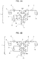
- Figs. 3A and 3B are each a schematic diagram of a flow passage of a liquid chromatograph 1 according to First Embodiment of the invention.
- Figs. 3A and 3B each show a schematic diagram of the flow passage of the liquid chromatograph 1 having a flow passage switching valve 5 of First Embodiment of the invention.
- the liquid chromatograph 1 includes a liquid sending pump 2, a needle 3, a syringe pump 4, the flow passage switching valve 5, a separation column 6, a detector 7, and pipes for coupling such components together.
- the stationary stator flow passages 31, 32, 33, 34, 35, and 36 of the flow passage switching valve 5 are coupled to the liquid sending pump 2, the separation column 6, a needle port 10, a waste liquid tank 11, the syringe pump 4, and the needle 3, respectively.
- an eluent 9 sent by the liquid sending pump 2 flows to the separation column 6, the detector 7, and a waste liquid tank 16 through the stationary stator flow passage 31, the rotor flow passage 241, and the stationary stator flow passage 32.
- the needle port 10 is coupled to the waste liquid tank 11 via the stationary stator flow passage 33, the rotor flow passage 243, and the stationary stator flow passage 34, and the syringe pump 4 is coupled to the needle 3 via the stationary stator flow passage 35, the rotor flow passage 242, and the stationary stator flow passage 36.
- the syringe pump 4 performs sucking operation so that a sample 8 is sucked into the needle 3.
- the rotor seal 22 is rotated 60° in the sliding direction 29 (clockwise) to switch a flow passage, so that the state of Fig. 3B is given.
- the needle 3 holding the sample 8 is moved and coupled to the needle port 10.
- the eluent is sent by the liquid sending pump 2 to send the sample 8 in the needle 3 to the separation column 6, the sample 8 is separated by the separation column 6, and the separated sample is detected by the detector 7.
- the eluent is sent to wash the flow passage through which the sample has flown.
- the rotor seal 22 in the state of Fig. 3B is rotated 60° in the direction opposite to the sliding direction 29 (counterclockwise), so that the state is returned to the state of Fig. 3A .
- the eluent is flown by the liquid sending pump 2 and the syringe pump 4 to wash the flow passage. The above operation is repeated for each sample to be analyzed.
- the separation column 6 is internally filled with particles several micrometers in size and has a large fluid resistance.
- the liquid sending pump 2 sends the eluent at a high pressure of tens of megapascal (MPa) .
- MPa megapascal
- liquid sending pressure of the syringe pump 4 is close to atmospheric pressure (0.1 MPa). In the state of Fig. 3A , therefore, liquid pressure is high in the rotor flow passage 241 but low in each of the rotor flow passages 242 and 243.
- Fig. 4 illustrates an exemplary configuration of a flow passage switching valve system including the flow passage switching valve 5 according to First Embodiment of the invention.
- the flow passage switching valve system includes the flow passage switching valve 5 and a control device 500 that controls rotation of a rotor of the flow passage switching valve 5.
- the control device 500 can be configured using, for example, a computer having a known configuration, and includes a calculation unit performing calculation and a storage unit storing information.
- the calculation unit includes, for example, a processor, and the storage unit includes, for example, a semiconductor memory.
- the storage unit can store a program and the calculation unit executes the program, through which the control device 500 implements such processing and controls the flow passage switching valve 5.
- Fig. 5 is used to describe an operation of the flow passage switching valve 5 according to First Embodiment of the invention and describe an abrasion area.
- the flow passage switching valve 5 switches a flow passage by continuously rotating the rotor seal 22 in the same direction, and thus the operating life of the valve is prolonged.
- the flow passage switching valve 5 achieves a plurality of coupling patterns in a switchable manner, and specifically achieves any one of the coupling patterns in correspondence to rotation of the rotor.
- six coupling patterns shown in Fig. 5 can be achieved.
- a pattern shown in Fig. 5A is a first coupling pattern
- a pattern shown in Fig. 5F is a second coupling pattern
- a pattern shown in Fig. 5C is a third coupling pattern
- a pattern shown in Fig. 5B is a fourth coupling pattern.
- respective positions of the stationary stator flow passages 31 to 36 of Figs. 5A to 5F correspond to the positions shown in Fig. 3A or 3B .
- the rotor flow passage 241 couples the stationary stator flow passages 31 and 32 together
- the rotor flow passage 242 couples the stationary stator flow passages 35 and 36 together
- the rotor flow passage 243 couples the stationary stator flow passages 33 and 34 together.
- contact pressure is high in the vicinity of the area 200 of the rotor seal 22 in Fig. 5A .
- a state of Fig. 5B is given.
- the rotor flow passage 241 couples the stationary stator flow passages 32 and 33 together
- the rotor flow passage 242 couples the stationary stator flow passages 36 and 31 together
- the rotor flow passage 243 couples the stationary stator flow passages 34 and 35 together.
- contact pressure is high in the vicinity of the area 201 on the rotor seal 22.
- the rotor seal 22 is further rotated 60° in the sliding direction 29, so that a state of Fig. 5C is given.
- the rotor flow passage 241 couples the stationary stator flow passages 33 and 34 together
- the rotor flow passage 242 couples the stationary stator flow passages 31 and 32 together
- the rotor flow passage 243 couples the stationary stator flow passages 35 and 36 together.
- contact pressure is high in the vicinity of the area 202 on the rotor seal 22.
- the area 200 on the rotor seal 22 does not return to the original position but moves to a position rotated 120° in the sliding direction 29, i.e., moves to the upper left position in Fig. 5C .
- the rotor seal 22 is further rotated 60° in the sliding direction 29, so that a state of Fig. 5D is given.
- the rotor flow passage 241 couples the stationary stator flow passages 34 and 35 together
- the rotor flow passage 242 couples the stationary stator flow passages 32 and 33 together
- the rotor flow passage 243 couples the stationary stator flow passages 36 and 31 together.
- the rotor seal 22 is further rotated 60° in the sliding direction 29, so that a state of Fig. 5E is given.
- the rotor flow passage 241 couples the stationary stator flow passages 35 and 36 together
- the rotor flow passage 242 couples the stationary stator flow passages 33 and 34 together
- the rotor flow passage 243 couples the stationary stator flow passages 31 and 32 together.
- the rotor seal 22 is further rotated 60° in the sliding direction 29, so that a state of Fig. 5F is given.
- the rotor flow passage 241 couples the stationary stator flow passages 36 and 31 together
- the rotor flow passage 242 couples the stationary stator flow passages 34 and 35 together
- the rotor flow passage 243 couples the stationary stator flow passages 32 and 33 together.
- the rotor seal 22 is further rotated 60° in the sliding direction 29, so that the state of Fig. 5A is given again.
- the areas 200 to 206 that have experienced the state of high contact surface pressure are dispersed around the entire circumference on the rotor seal 22. This disperses the abrasion area of the rotor seal 22, leading to a long operating life compared with a case using a conventional drive method.
- the rotor seal 22 does not necessarily need to be constantly rotated in the same direction as in First Embodiment. In a possible modification, the rotor seal 22 may be rotated in the opposite direction according to a condition.
- Fig. 6 illustrates an exemplary operation according to such a modification.
- the control device 500 can operate in any one of a plurality of modes.
- the control device 500 can operate in any one of modes, including a mode in which the coupling pattern of Fig. 5A and the coupling pattern of Fig. 5B are alternately achieved (first mode), a mode in which the coupling pattern of Fig. 5C and the coupling pattern of Fig. 5D are alternately achieved (second mode), and a mode in which the coupling pattern of Fig. 5E and the coupling pattern of Fig. 5F are alternately achieved (third mode).
- control device 500 operates in the first mode and the rotor seal 22 performs a reciprocating motion between the states of Figs. 5A and 5B until a predetermined criterion is satisfied. Subsequently, when the predetermined criterion is satisfied, the rotor seal 22 is rotated 120° only once so that the mode is shifted to the second mode (for example, the state of Fig. 5C is given). The control device 500 then operates in the second mode and the rotor seal 22 performs a reciprocating motion between the states of Figs. 5C and 5D until the predetermined criterion is satisfied again.
- the rotor seal 22 is rotated 120° only once so that the mode is shifted to the third mode (for example, the state of Fig. 5E is given).
- the control device 500 then operates in the third mode and the rotor seal 22 performs a reciprocating motion between the states of Figs. 5E and 5F until the predetermined criterion is satisfied again.
- the rotor seal 22 is rotated 120° only once so that the mode is returned to the first mode (for example, the state is returned to the state of Fig. 5A ).
- Such an operation can also disperse the abrasion area around the entire circumference on the rotor seal 22.
- Each mode may include not only the above combination of the states but another combination of the states.
- the first mode may include the states of Figs. 5F and 5A
- the second mode may include the states of Figs. 5B and 5C
- the third mode may include the states of Figs. 5D and 5E .
- the predetermined criterion for shifting the mode can be optionally designed.
- the control device 500 may switch the mode based on the total rotation amount of the rotor.
- the total rotation amount refers to, for example, the number of rotations of the rotor seal 22 (or an integrated value of angles) up to that time.
- the control device 500 may switch the mode based on the total rotation time of the rotor.
- the total rotation time refers to, for example, an integrated value of time, during which the rotor seal 22 has performed the rotational operation, up to that time.
- the control device 500 may switch the mode based on the total operation time of the flow passage valve system.
- the total operation time refers to, for example, an integrated value of time, during which the flow passage valve system has been on, up to that time.
- the control device 500 may switch the mode based on fluid passing frequency in any one of the flow passages (i.e., any one of the stationary stator flow passages 31 to 36 and the rotor flow passages 241 to 243).
- the fluid passing frequency corresponds to execution frequency of analysis operation in the liquid chromatograph 1.
- the liquid chromatograph 1 may include a device that measures a state of a fluid in any one flow passage, and the control device 500 may receive a signal from such a device and switch a mode based on the signal.
- the control device 500 may switch the mode based on pressure in any one flow passage, based on the amount of change in pressure in any one flow passage, based on the total flow rate (for example, the total amount of the eluent) in any one flow passage, based on the leakage amount from any one flow passage, based on a change in the leakage amount from any one flow passage, or based on the carry-over amount in any one flow passage.
- the carry-over amount can be detected using the detector 7 by a predetermined analysis method, for example.
- a condition which is defined by combining at least two or all of the above-described criteria, may be used. Predefining such a criterion makes it possible to switch the mode at an appropriate timing and disperse the abrasion area more appropriately.
- First Embodiment the structure on the stator side of the sliding surface is fixed at any time.
- Second Embodiment the structure on the stator side of the sliding surface is partially rotatable. Differences from First Embodiment are now described.
- Figs. 7A to 7D illustrate an exemplary configuration of a flow passage switching valve 5 according to Second Embodiment of the invention.
- Second Embodiment differs from First Embodiment in that a middle stator seal 330 is provided between the stator main body 21 and the rotor seal 22 as shown in Figs. 7A to 7D .
- the stator main body 21 and the middle stator seal 330 collectively configure the stator.
- Fig. 7A shows a cross-sectional view as a plane parallel to an axis of the flow passage switching valve 5
- Fig. 7B shows a top view of the rotor seal 22
- Fig. 7C shows a top view of a portion of the middle stator seal 330 in contact with the rotor seal 22.
- the surface of the middle stator seal 330 shown in Fig. 7C is actually faces downward and cannot be seen from the above
- Fig. 7C shows a shape of the surface as viewed from the above for ease in understanding of overlapping with the rotor seal 22.
- Fig. 7D shows a positional relationship between each flow passage of the middle stator seal 330 and the rotor seal 22 when a contact surface of the middle stator seal 330 is set to overlap a contact surface of the rotor seal 22.
- a liquid chromatograph having a flow passage switching valve 5 of Second Embodiment of the invention is described with Figs. 3A and 3B , Figs. 7A to 7D , and Figs. 8A to 8C .
- the middle stator seal 330 is rotatably fixed to the stator main body 21.
- the rotational axis of the middle stator seal 330 is the same as the rotational axis of the rotor.
- the middle stator seal 330 is rotated with respect to the stator main body 21, thereby an abrasion area on the contact surface can be dispersed not only on a rotor side but also on a stator side.
- the middle stator seal 330 has middle stator seal flow passages 331 to 336 that are each coupled to any one of the stationary stator flow passages 31 to 36.
- a particular middle stator seal flow passage and a particular stationary stator flow passage to be coupled together are each different depending on a rotational position of the middle stator seal 330 with respect to the stator main body 21.
- the middle stator seal flow passages 331 to 336 each configure a stator flow passage of this embodiment.
- the rotor seal 22 of the flow passage switching valve 5 of Second Embodiment is pressed to the middle stator seal 330 by the rotor main body 23, which maintains fluid-tightness of each of the three flow passages.
- the three flow passages include a flow passage configured of the rotor flow passage 241, the stationary stator flow passages 31 and 32, and the middle stator seal flow passages 331 and 332 ( Fig.
- FIG. 7A shows such a flow passage), a flow passage configured of the rotor flow passage 242, the stationary stator flow passages 35 and 36, and the middle stator seal flow passages 335 and 336, and a flow passage configured of the rotor flow passage 243, the stationary stator flow passages 33 and 34, and the middle stator seal flow passages 333 and 334.
- the rotor seal 22 is fixed to the rotor main body 23 by a pin (not shown), and rotates by a motor (not shown) coupled to the rotor main body 23.
- Figs. 8A to 8C illustrate an operation method of the flow passage switching valve 5 according to Second Embodiment.
- the state of Fig. 8A shows one of coupling patterns achieved in the first mode, which corresponds to the state of Figs. 7A to 7D .
- the flow passage switching valve 5 operates while switching between two coupling patterns including the coupling pattern of Fig. 8A .
- the coupling pattern of Fig. 8A and a coupling pattern in a state which is given by rotating the rotor in the state of Fig. 8A by 60° in the sliding direction 29, are achieved while being switched to each other.
- a state of Fig. 8B is given.
- the state of Fig. 8B shows one of coupling patterns achieved in the second mode.
- the flow passage switching valve 5 operates while switching between two coupling patterns including the coupling pattern of Fig. 8B .
- the coupling pattern of Fig. 8B and a coupling pattern in a state which is given by rotating the rotor in the state of Fig. 8B by 60° in the sliding direction 29, are achieved while being switched to each other.
- the middle stator seal flow passage 335, the rotor flow passage 241, and the middle stator seal flow passage 336 are each coupled to the liquid sending pump 2 and the separation column 6 in Figs. 3A and 3B .
- the middle stator seal flow passage 331, the rotor flow passage 243, and the middle stator seal flow passage 332 are each coupled to the needle port 10 and the waste liquid tank 11.
- the middle stator seal flow passage 333, the rotor flow passage 242, and the middle stator seal flow passage 334 are each coupled to the needle 3 and the syringe pump 4 in Figs. 3A and 3B .
- a state of Fig. 8C is given.
- the state of Fig. 8C shows one of the coupling patterns achieved in the third mode.
- the flow passage switching valve 5 operates while switching between two coupling patterns including the coupling pattern of Fig. 8C .
- the coupling pattern of Fig. 8C and a coupling pattern in a state which is given by rotating the rotor in the state of Fig. 8C by 60° in the sliding direction 29, are achieved while being switched to each other.
- the middle stator seal flow passage 333, the rotor flow passage 241, and the middle stator seal flow passage 334 are each coupled to the liquid sending pump 2 and the separation column 6 in Figs. 3A and 3B .
- the middle stator seal flow passage 335, the rotor flow passage 243, and the middle stator seal flow passage 336 are each coupled to the needle port 10 and the waste liquid tank 11.
- the middle stator seal flow passage 331, the rotor flow passage 242, and the middle stator seal flow passage 332 are each coupled to the needle 3 and the syringe pump 4 in Figs. 3A and 3B .
- a method and a configuration for rotating the middle stator seal 330 can be optionally designed by those skilled in the art.
- the middle stator seal 330 may be manually rotated by a user of a liquid chromatograph or may be automatically rotated by the control device 500 or another device.
- a tool (not shown) is inserted into a rotation groove 328 of the middle stator seal 330 through the position detection window 30 in Figs. 7A to 7D to rotate the middle stator seal 330.
- an axially protruding convex portion (not shown) is provided in the center of rotation of the middle stator seal 330
- an axially depressed concave portion (not shown) is provided in the center of the stator main body 21, and such convex and concave portions are physically combined and rotatably engaged together, thereby a rotational axis of the middle stator seal can be configured.
- a structure (such as a locking mechanism) that fix and hold the middle stator seal 330 to the stator main body 21 may be provided to prevent corotation of the middle stator seal 330 during rotation of the rotor seal 22.
- Such rotation of the middle stator seal 330 achieves, in a more balanced manner, a state of high liquid pressure of each of the middle stator seal flow passages 331 and 332, a state of high liquid pressure of each of the middle stator seal flow passages 333 and 334, and a state of high liquid pressure of each of the middle stator seal flow passages 335 and 336.
- the rotation achieves, in a more balanced manner, a state of high contact pressure of an area opposed to the middle stator seal flow passages 331 and 332, a state of high contact pressure of an area opposed to the middle stator seal flow passages 333 and 334, and a state of high contact pressure of an area opposed to the middle stator seal flow passages 335 and 336.
- an abrasion area of the middle stator seal 330 is dispersed, leading to a long operating life compared with a case using a conventional drive method.
- the timing for rotating the middle stator seal 330 can be determined based on a criterion similar to the criterion for timing to switch the mode as described in the modification shown in Fig. 6 .
- the mode switching of rotor rotation as in Fig. 6 and the mode switching of rotation of the middle stator seal 330 according to Second Embodiment may be performed in a combined manner.
- both switching timings are preferably designed so as not to coincide with each other to avoid a fixed positional relationship between the rotor seal 22 and the middle stator seal 330.
- the number of the flow passages or the coupling patterns may be appropriately changed depending on applications of the flow passage switching valve.
- At least three stator flow passages (stationary stator flow passages in First Embodiment, middle stator flow passages in Second Embodiment), at least two rotor flow passages, and at least four coupling patterns may be provided.
- stator flow passages including only the stationary stator flow passages 31, 32, and 36 as shown in Figs. 5A to 5F
- rotor flow passages including only the rotor flow passages 241 and 242 as shown in Figs. 5A to 5F
- at least four coupling patterns corresponding to Figs.
- each rotor flow passage need not necessarily be configured to couple two stator flow passages together in any of the coupling patterns (for example, in the pattern of Fig. 5A , when the stationary stator flow passages 33 to 35 do not exist, the rotor flow passage 242 is in communication with only the stationary stator flow passage 36 without coupling two stator flow passages together).
- the control device 500 may operate only in the first and second modes without the third mode while switching between the first and second modes.
- the abrasion area can also be dispersed in some degree (not around the entire circumference but in two or more points).
- the number of modes may be at least two.
- the number of modes may be two so that two coupling patterns are alternately achieved in the first mode while other two coupling patterns are alternately achieved in the second mode.
- the coupling pattern of Fig. 5A and one of the coupling patterns of Figs. 5B and 5F may be alternately achieved in the first mode, and two specific coupling patterns, which are not achieved in the first mode, may be achieved in the second mode.
- the above "two specific coupling patterns that are not achieved in the first mode” includes the coupling pattern of Fig. 5C and another coupling pattern.
- another coupling pattern includes, for example, one of the coupling patterns of Figs. 5B and 5F , which is not achieved in the first mode, but may be the coupling pattern of Fig. 5D or an appropriately configured coupling pattern other than such coupling patterns.
Landscapes
- Engineering & Computer Science (AREA)
- General Engineering & Computer Science (AREA)
- Mechanical Engineering (AREA)
- General Health & Medical Sciences (AREA)
- Analytical Chemistry (AREA)
- Biochemistry (AREA)
- Physics & Mathematics (AREA)
- General Physics & Mathematics (AREA)
- Immunology (AREA)
- Pathology (AREA)
- Chemical & Material Sciences (AREA)
- Life Sciences & Earth Sciences (AREA)
- Health & Medical Sciences (AREA)
- Multiple-Way Valves (AREA)
Applications Claiming Priority (2)
| Application Number | Priority Date | Filing Date | Title |
|---|---|---|---|
| JP2019190312A JP7303723B2 (ja) | 2019-10-17 | 2019-10-17 | 流路切替バルブシステムおよび液体クロマトグラフ |
| PCT/JP2020/034266 WO2021075184A1 (ja) | 2019-10-17 | 2020-09-10 | 流路切替バルブ、流路切替バルブシステムおよび液体クロマトグラフ |
Publications (2)
| Publication Number | Publication Date |
|---|---|
| EP4047362A1 true EP4047362A1 (de) | 2022-08-24 |
| EP4047362A4 EP4047362A4 (de) | 2023-11-08 |
Family
ID=75537821
Family Applications (1)
| Application Number | Title | Priority Date | Filing Date |
|---|---|---|---|
| EP20877089.1A Pending EP4047362A4 (de) | 2019-10-17 | 2020-09-10 | Durchflusswegschaltventil, durchflusswegschaltventilsystem und flüssigkeitschromatograf |
Country Status (5)
| Country | Link |
|---|---|
| US (1) | US12247959B2 (de) |
| EP (1) | EP4047362A4 (de) |
| JP (1) | JP7303723B2 (de) |
| CN (1) | CN114466984B (de) |
| WO (1) | WO2021075184A1 (de) |
Families Citing this family (3)
| Publication number | Priority date | Publication date | Assignee | Title |
|---|---|---|---|---|
| CN114746752B (zh) | 2019-11-27 | 2024-10-29 | 沃特世科技公司 | 有源阻尼梯度比例阀 |
| JP7474691B2 (ja) * | 2020-12-15 | 2024-04-25 | 株式会社日立ハイテク | 流路切替バルブおよび液体クロマトグラフ |
| EP4435243A4 (de) * | 2022-10-17 | 2025-01-15 | Johnson Electric International AG | Wärmeverwaltungssystem und ventil dafür |
Family Cites Families (30)
| Publication number | Priority date | Publication date | Assignee | Title |
|---|---|---|---|---|
| JPS5196391A (de) * | 1975-02-21 | 1976-08-24 | ||
| US4068528A (en) * | 1976-01-19 | 1978-01-17 | Rheodyne Incorporated | Two position rotary valve for injecting sample liquids into an analysis system |
| US6012487A (en) | 1997-03-10 | 2000-01-11 | Brian A. Hauck | Prime purge injection valve or multi-route selections valve |
| US5958227A (en) * | 1997-07-15 | 1999-09-28 | Tosoh Corporation | Liquid chromatograph apparatus with a switching valve |
| JP4019372B2 (ja) * | 2003-06-18 | 2007-12-12 | 王子製紙株式会社 | 液体試料注入装置 |
| US8047060B2 (en) * | 2005-01-31 | 2011-11-01 | Waters Technologies Corporation | Method and apparatus for sample injection in liquid chromatography |
| US8881582B2 (en) * | 2005-01-31 | 2014-11-11 | Waters Technologies Corporation | Method and apparatus for sample injection in liquid chromatography |
| JP4913470B2 (ja) * | 2006-04-26 | 2012-04-11 | 株式会社島津製作所 | 流路切換えバルブを用いた高速液体クロマトグラフ及び分析方法 |
| US7854793B2 (en) | 2006-06-30 | 2010-12-21 | David Lester Rarig | Pressure swing adsorption system with indexed rotatable multi-port valves |
| JP4983292B2 (ja) * | 2007-02-19 | 2012-07-25 | 株式会社島津製作所 | 流路切換えバルブ |
| JP4862947B2 (ja) | 2007-09-28 | 2012-01-25 | 株式会社島津製作所 | 試料導入装置 |
| DE102007059651B4 (de) * | 2007-12-10 | 2017-05-24 | Dionex Softron Gmbh | Probengeber für die Hochleistungsflüssigkeitschromatographie |
| WO2009078450A1 (ja) * | 2007-12-17 | 2009-06-25 | Shimadzu Corporation | 流路切換えバルブ |
| DE102008006266B4 (de) * | 2008-01-25 | 2011-06-09 | Dionex Softron Gmbh | Probengeber für die Flüssigkeitschromatographie, insbesondere für die Hochleistungsflüssigkeitschromatographie |
| JP2009276110A (ja) * | 2008-05-13 | 2009-11-26 | Tosoh Corp | クロマトグラフ分析装置用試料注入システム |
| EP2370193B1 (de) * | 2008-12-04 | 2012-11-14 | Vrije Universiteit Brussel | Chromatographische trennungsvorrichtung mit variabler länge und einem verfahren zu deren verwendung |
| WO2011001460A1 (ja) * | 2009-06-29 | 2011-01-06 | 株式会社島津製作所 | 流路切換バルブ |
| US9115815B2 (en) * | 2010-08-27 | 2015-08-25 | Waters Technologies Corporation | Variable-volume injection valve |
| US9939415B2 (en) * | 2011-01-12 | 2018-04-10 | Dionex Softron Gmbh | High-pressure control valve for high-performance liquid chromatography |
| US9435775B2 (en) * | 2011-02-07 | 2016-09-06 | Waters Technologies Corporation | Fluid switching valve |
| JP2014520250A (ja) * | 2011-04-25 | 2014-08-21 | ウオーターズ・テクノロジーズ・コーポレイシヨン | 保護被膜を有するバルブ |
| EP2807410B1 (de) | 2012-07-17 | 2017-08-30 | Idex Health & Science LLC | Verfahren zur übertragung einer flüssigen probe mittels eines probeentnahmeventils |
| JP2013047695A (ja) * | 2012-12-05 | 2013-03-07 | Tosoh Corp | クロマトグラフ分析装置用試料注入システム |
| WO2015079534A1 (ja) * | 2013-11-28 | 2015-06-04 | 株式会社日立製作所 | 分析用試料の前処理装置及びそれを用いた分析システム |
| JP5865403B2 (ja) * | 2014-02-12 | 2016-02-17 | 株式会社日立ハイテクノロジーズ | 流路切り替えバルブおよび当該バルブを用いた液体クロマトグフラフ装置 |
| DE102016101658B4 (de) * | 2016-01-29 | 2018-04-05 | Dionex Softron Gmbh | Probenvorkompressionsventil für die Flüssigkeitschromatographie, insbesondere für die Hochleistungsflüssigkeitschromatographie |
| US11385208B2 (en) * | 2016-03-07 | 2022-07-12 | Hitachi High-Tech Corporation | Analysis device |
| EP3252464B1 (de) * | 2016-05-30 | 2024-03-27 | Agilent Technologies, Inc. (A Delaware Corporation) | Injektor und verfahren zur probeninjektion mit flüssigkeitsverbindung zwischen einer flüssigkeitsantriebseinheit und einem probenaufnahmevolumen |
| JP2019190312A (ja) | 2018-04-20 | 2019-10-31 | 株式会社東芝 | プラント制御装置および発電プラント |
| JP7133499B2 (ja) * | 2019-03-07 | 2022-09-08 | 株式会社日立ハイテク | 流路切替バルブ及びそれを有する液体クロマトグラフ |
-
2019
- 2019-10-17 JP JP2019190312A patent/JP7303723B2/ja active Active
-
2020
- 2020-09-10 CN CN202080069904.3A patent/CN114466984B/zh active Active
- 2020-09-10 WO PCT/JP2020/034266 patent/WO2021075184A1/ja not_active Ceased
- 2020-09-10 US US17/764,613 patent/US12247959B2/en active Active
- 2020-09-10 EP EP20877089.1A patent/EP4047362A4/de active Pending
Also Published As
| Publication number | Publication date |
|---|---|
| JP7303723B2 (ja) | 2023-07-05 |
| US20220326197A1 (en) | 2022-10-13 |
| CN114466984A (zh) | 2022-05-10 |
| EP4047362A4 (de) | 2023-11-08 |
| JP2021067458A (ja) | 2021-04-30 |
| US12247959B2 (en) | 2025-03-11 |
| CN114466984B (zh) | 2024-04-26 |
| WO2021075184A1 (ja) | 2021-04-22 |
Similar Documents
| Publication | Publication Date | Title |
|---|---|---|
| US12247959B2 (en) | Flow passage switching valve, flow passage switching valve system, and liquid chromatograph | |
| CN102472400B (zh) | 液相色谱仪系统 | |
| CN101849126B (zh) | 通道转换阀 | |
| JP7060903B2 (ja) | 流体交差防止可能な切り替え弁 | |
| GB2529312A (en) | Multi-Path Selector Valve | |
| CA2577824A1 (en) | Rotary valve and analytical chromatographic system using the same | |
| US8960231B2 (en) | Multi-mode injection valve | |
| US10113995B2 (en) | Multi-position, micro-fluidic valve assembly with multiple radial grooves to enable individual or combined flows | |
| US20140007660A1 (en) | Fluid Switching Valve | |
| JP7133499B2 (ja) | 流路切替バルブ及びそれを有する液体クロマトグラフ | |
| JP2018511801A (ja) | 回転バルブおよびクロマトグラフィシステム | |
| US20180106388A1 (en) | Cleaning of rotary valves | |
| KR20080015398A (ko) | 실링구조 및 그 실링구조를 이용한 제어밸브 | |
| JPWO2014141358A1 (ja) | 流路切換バルブ | |
| CN106102913B (zh) | 旋转式取样阀以及装备有此类阀的装置 | |
| US20130340509A1 (en) | Flow Through Isolation Valve For High Pressure Fluids | |
| US20190212231A1 (en) | Systems and methods for solid phase extraction for chromotographic analysis | |
| US20070137713A1 (en) | Combination flow through injection and isolation valve for high pressure fluids |
Legal Events
| Date | Code | Title | Description |
|---|---|---|---|
| STAA | Information on the status of an ep patent application or granted ep patent |
Free format text: STATUS: THE INTERNATIONAL PUBLICATION HAS BEEN MADE |
|
| PUAI | Public reference made under article 153(3) epc to a published international application that has entered the european phase |
Free format text: ORIGINAL CODE: 0009012 |
|
| STAA | Information on the status of an ep patent application or granted ep patent |
Free format text: STATUS: REQUEST FOR EXAMINATION WAS MADE |
|
| 17P | Request for examination filed |
Effective date: 20220331 |
|
| AK | Designated contracting states |
Kind code of ref document: A1 Designated state(s): AL AT BE BG CH CY CZ DE DK EE ES FI FR GB GR HR HU IE IS IT LI LT LU LV MC MK MT NL NO PL PT RO RS SE SI SK SM TR |
|
| DAV | Request for validation of the european patent (deleted) | ||
| DAX | Request for extension of the european patent (deleted) | ||
| A4 | Supplementary search report drawn up and despatched |
Effective date: 20231010 |
|
| RIC1 | Information provided on ipc code assigned before grant |
Ipc: G01N 30/20 20060101ALI20231004BHEP Ipc: F16K 37/00 20060101ALI20231004BHEP Ipc: F16K 11/074 20060101ALI20231004BHEP Ipc: G01N 30/26 20060101AFI20231004BHEP |
|
| STAA | Information on the status of an ep patent application or granted ep patent |
Free format text: STATUS: EXAMINATION IS IN PROGRESS |
|
| 17Q | First examination report despatched |
Effective date: 20250515 |