EP3936724B1 - Spiralverdichter - Google Patents
Spiralverdichter Download PDFInfo
- Publication number
- EP3936724B1 EP3936724B1 EP19925324.6A EP19925324A EP3936724B1 EP 3936724 B1 EP3936724 B1 EP 3936724B1 EP 19925324 A EP19925324 A EP 19925324A EP 3936724 B1 EP3936724 B1 EP 3936724B1
- Authority
- EP
- European Patent Office
- Prior art keywords
- end plate
- orbiting
- fixed
- axis
- scroll
- Prior art date
- Legal status (The legal status is an assumption and is not a legal conclusion. Google has not performed a legal analysis and makes no representation as to the accuracy of the status listed.)
- Active
Links
Images


Classifications
-
- F—MECHANICAL ENGINEERING; LIGHTING; HEATING; WEAPONS; BLASTING
- F01—MACHINES OR ENGINES IN GENERAL; ENGINE PLANTS IN GENERAL; STEAM ENGINES
- F01C—ROTARY-PISTON OR OSCILLATING-PISTON MACHINES OR ENGINES
- F01C17/00—Arrangements for drive of co-operating members, e.g. for rotary piston and casing
- F01C17/06—Arrangements for drive of co-operating members, e.g. for rotary piston and casing using cranks, universal joints or similar elements
- F01C17/066—Arrangements for drive of co-operating members, e.g. for rotary piston and casing using cranks, universal joints or similar elements with an intermediate piece sliding along perpendicular axes, e.g. Oldham coupling
-
- F—MECHANICAL ENGINEERING; LIGHTING; HEATING; WEAPONS; BLASTING
- F01—MACHINES OR ENGINES IN GENERAL; ENGINE PLANTS IN GENERAL; STEAM ENGINES
- F01C—ROTARY-PISTON OR OSCILLATING-PISTON MACHINES OR ENGINES
- F01C21/00—Component parts, details or accessories not provided for in groups F01C1/00 - F01C20/00
- F01C21/007—General arrangements of parts; Frames and supporting elements
-
- F—MECHANICAL ENGINEERING; LIGHTING; HEATING; WEAPONS; BLASTING
- F04—POSITIVE - DISPLACEMENT MACHINES FOR LIQUIDS; PUMPS FOR LIQUIDS OR ELASTIC FLUIDS
- F04C—ROTARY-PISTON, OR OSCILLATING-PISTON, POSITIVE-DISPLACEMENT MACHINES FOR LIQUIDS; ROTARY-PISTON, OR OSCILLATING-PISTON, POSITIVE-DISPLACEMENT PUMPS
- F04C18/00—Rotary-piston pumps specially adapted for elastic fluids
- F04C18/02—Rotary-piston pumps specially adapted for elastic fluids of arcuate-engagement type, i.e. with circular translatory movement of co-operating members, each member having the same number of teeth or tooth-equivalents
-
- F—MECHANICAL ENGINEERING; LIGHTING; HEATING; WEAPONS; BLASTING
- F04—POSITIVE - DISPLACEMENT MACHINES FOR LIQUIDS; PUMPS FOR LIQUIDS OR ELASTIC FLUIDS
- F04C—ROTARY-PISTON, OR OSCILLATING-PISTON, POSITIVE-DISPLACEMENT MACHINES FOR LIQUIDS; ROTARY-PISTON, OR OSCILLATING-PISTON, POSITIVE-DISPLACEMENT PUMPS
- F04C18/00—Rotary-piston pumps specially adapted for elastic fluids
- F04C18/02—Rotary-piston pumps specially adapted for elastic fluids of arcuate-engagement type, i.e. with circular translatory movement of co-operating members, each member having the same number of teeth or tooth-equivalents
- F04C18/0207—Rotary-piston pumps specially adapted for elastic fluids of arcuate-engagement type, i.e. with circular translatory movement of co-operating members, each member having the same number of teeth or tooth-equivalents both members having co-operating elements in spiral form
- F04C18/0215—Rotary-piston pumps specially adapted for elastic fluids of arcuate-engagement type, i.e. with circular translatory movement of co-operating members, each member having the same number of teeth or tooth-equivalents both members having co-operating elements in spiral form where only one member is moving
-
- F—MECHANICAL ENGINEERING; LIGHTING; HEATING; WEAPONS; BLASTING
- F04—POSITIVE - DISPLACEMENT MACHINES FOR LIQUIDS; PUMPS FOR LIQUIDS OR ELASTIC FLUIDS
- F04C—ROTARY-PISTON, OR OSCILLATING-PISTON, POSITIVE-DISPLACEMENT MACHINES FOR LIQUIDS; ROTARY-PISTON, OR OSCILLATING-PISTON, POSITIVE-DISPLACEMENT PUMPS
- F04C18/00—Rotary-piston pumps specially adapted for elastic fluids
- F04C18/02—Rotary-piston pumps specially adapted for elastic fluids of arcuate-engagement type, i.e. with circular translatory movement of co-operating members, each member having the same number of teeth or tooth-equivalents
- F04C18/0207—Rotary-piston pumps specially adapted for elastic fluids of arcuate-engagement type, i.e. with circular translatory movement of co-operating members, each member having the same number of teeth or tooth-equivalents both members having co-operating elements in spiral form
- F04C18/0246—Details concerning the involute wraps or their base, e.g. geometry
- F04C18/0253—Details concerning the base
-
- F—MECHANICAL ENGINEERING; LIGHTING; HEATING; WEAPONS; BLASTING
- F04—POSITIVE - DISPLACEMENT MACHINES FOR LIQUIDS; PUMPS FOR LIQUIDS OR ELASTIC FLUIDS
- F04C—ROTARY-PISTON, OR OSCILLATING-PISTON, POSITIVE-DISPLACEMENT MACHINES FOR LIQUIDS; ROTARY-PISTON, OR OSCILLATING-PISTON, POSITIVE-DISPLACEMENT PUMPS
- F04C29/00—Component parts, details or accessories of pumps or pumping installations, not provided for in groups F04C18/00 - F04C28/00
- F04C29/0042—Driving elements, brakes, couplings, transmissions specially adapted for pumps
- F04C29/005—Means for transmitting movement from the prime mover to driven parts of the pump, e.g. clutches, couplings, transmissions
- F04C29/0057—Means for transmitting movement from the prime mover to driven parts of the pump, e.g. clutches, couplings, transmissions for eccentric movement
Definitions
- the present invention relates to a scroll compressor.
- a scroll compressor used in an air conditioning device, a refrigerating device, or the like to compress a refrigerant is generally known.
- the refrigerant is compressed by causing an orbiting scroll to orbit with respect to a fixed scroll.
- PTL 2 and PTL 3 each disclose a scroll compressor with Oldham ring.
- the present invention provides a scroll compressor which is compact while supporting high pressure and increasing the capacity.
- a scroll compressor includes a rotating shaft that extends along an axis; a motor that rotates the rotating shaft; a scroll compression portion that compresses a refrigerant by the rotation of the rotating shaft; and a housing that houses the rotating shaft, the motor, and the scroll compression portion, in which the scroll compression portion includes a fixed scroll that has a fixed end plate fixed to the housing, and a fixed wrap that protrudes from the fixed end plate in a direction of the axis, an orbiting scroll that is provided to the rotating shaft, and has an orbiting end plate disposed to face the fixed end plate in the direction of the axis, and an orbiting wrap that protrudes from the orbiting end plate toward the fixed end plate and forms a compression chamber for the refrigerant together with the fixed wrap, and an Oldham ring that is interposed between the fixed end plate and the orbiting end plate, and supports the orbiting scroll such that the orbiting scroll orbits around the axis without rotating, the Oldham ring has
- the fixed end plate is provided with the annular groove, and a part of the ring body is disposed in the annular groove. Therefore, even when the thickness dimension of the Oldham ring in the direction of the axis is increased in order to support high pressure and increase the capacity, the fixed end plate can be disposed to be closer to the orbiting end plate. Thus, the scroll compression portion can be made compact in the direction of the axis.
- the lubricant When the lubricant is introduced to the scroll compression portion, the lubricant can be held in the annular groove, the operation of the scroll compression portion can be smoothed, and the efficiency can be improved.
- the key groove in the fixed end plate may be recessed from the annular groove in the direction away from the orbiting end plate in the direction of the axis, and may be provided to extend from the annular groove to an outer side of the annular groove in the radial direction.
- the machining start point of the end mill is formed in an arc shape following the outer shape of the drill.
- the side surfaces of the key groove facing in the circumferential direction can be formed in a planar shape along the radial direction in the annular groove, and therefore, the key groove having planar-shaped side surfaces can be easily formed in the annular groove.
- the thickness of the fixed end plate in the direction of the axis is larger than the thickness in the direction of the axis at the position where the annular groove is formed. Therefore, even when the key groove is formed to extend to the outer side of the annular groove in the radial direction, a problem in strength is unlikely to occur.
- a bottom surface of the annular groove and the front surface of the ring body may be provided with an interval in the direction of the axis.
- the front surface of the ring body is less likely to come into contact with the bottom surface of the annular groove.
- the friction loss between the Oldham ring and the fixed end plate can be reduced.
- the orbiting end plate has a thick portion that has a disk shape and is provided with the orbiting wrap, and a thin portion which is integrally provided with the thick portion on an outer side of the thick portion in a radial direction, has an annular shape, and has a smaller thickness dimension in the direction of the axis than a thickness dimension of the thick portion, and of which an end face facing the fixed end plate side is disposed at a position away from the fixed end plate as compared with the thick portion, and the ring body may be provided to be placed on the end face of the thin portion.
- the orbiting end plate of the orbiting scroll has the thick portion and the thin portion, and the ring body of the Oldham ring is provided over the annular groove of the fixed end plate and the thin portion of the orbiting end plate.
- the fixed end plate and the orbiting end plate can be closer to each other in the direction of the axis. Accordingly, the scroll compression portion can be made more compact in the direction of the axis.
- the thin portion is provided on the outer side of the orbiting end plate in the radial direction. Therefore, the weight of the outer end portion of the orbiting end plate in the radial direction can be reduced, and the moment of inertia when the orbiting end plate orbits around the axis of the rotating shaft can be reduced.
- the outer end portion of the orbiting end plate in the radial direction is less affected by a compressive load than the central portion of the orbiting end plate, and therefore, even in a case where the thin portion is provided, a problem in strength is unlikely to occur.
- the vibration can be suppressed.
- a vertical sealed two stage compressor having two compression portions 4 and 5 is described as an example of the scroll compressor 1, but the scroll compressor 1 is not limited to such a compressor, and the scroll compressor 1 may be a single stage compressor having only one compression portion, or may be a horizontal compressor, for example.
- the scroll compressor 1 includes a rotating shaft 2, a motor 3 that rotates the rotating shaft 2, and a rotary compression portion 4 and a scroll compression portion 5 that compress a refrigerant by the rotation of the rotating shaft 2.
- the scroll compressor 1 further includes a housing 6 that seals and houses the rotating shaft 2, the motor 3, the rotary compression portion 4, and the scroll compression portion 5.
- the rotating shaft 2 has a columnar shape centered on an axis O1 extending in a vertical direction.
- An eccentric shaft 8 having a columnar shape centered on an axis 02 disposed at a position shifted from the axis O1 in a radial direction is integrally provided at the upper end of the rotating shaft 2.
- the housing 6 has a tubular shape extending in the vertical direction along the axis O1 of the rotating shaft 2.
- the housing 6 is formed by casting, for example.
- the housing 6 has a housing main body 10 that has a cylindrical shape, an upper lid 11 that closes the upper opening of the housing main body 10, and a lower lid 12 that closes the lower opening of the housing main body 10.
- the housing 6 has a sealed space S extending in the vertical direction inside. Oil (lubricant) is stored from the lower portion of the housing main body 10 to the bottom portion of the lower lid 12, and an oil reservoir OL is formed at this position.
- a suction pipe 13 that introduces the refrigerant from the outside into the space S is connected to the lower portion of the housing 6. Further, a discharge pipe 14 that discharges the refrigerant from the space S to the outside is connected to the upper portion of the housing 6.
- a rotary lower bearing 20, a rotary upper bearing 21, and a scroll bearing 22 which rotatably support the rotating shaft 2 with respect to the housing 6 are provided inside the housing 6.
- the rotary lower bearing 20 and the rotary upper bearing 21 are provided to the rotary compression portion 4, and the scroll bearing 22 is provided to the scroll compression portion 5.
- the scroll compression portion 5 has an Oldham ring 50 that engages the fixed scroll 40 and the orbiting scroll 43.
- the fixed scroll 40 has a fixed end plate 41 that is below the discharge pipe 14, is fixed to the housing 6, and has a disk shape centered on the axis O1, and a fixed wrap 42 that protrudes downward from the fixed end plate 41 and has a spiral shape with reference to the axis O1.
- the fixed end plate 41 has a contact surface 41a on the outer side of the fixed wrap 42 in the radial direction, and the contact surface 41a faces downward in the direction of the axis O1, and is in surface contact with the scroll bearing 22.
- An annular groove 41b that has an annular shape centered on the axis O1 is provided between the fixed wrap 42 and the contact surface 41a.
- the annular groove 41b is recessed upward in the direction of the axis O1 with respect to the contact surface 41a and an edge 42a of the tip of the fixed wrap 42.
- the contact surface 41a of the fixed end plate 41 and the edge 42a of the fixed wrap 42 are disposed on the same plane.
- the contact surface 41a and the edge 42a of the fixed wrap 42 are not arranged exactly on the same plane, and the edge 42a of the fixed wrap 42 may be disposed above the contact surface 41a.
- the fixed end plate 41 is provided with a pair of fixed-side key grooves 41c at intervals of 180 degrees in the circumferential direction.
- the fixed-side key groove 41c extends from a position close to the fixed wrap 42 to a position in the middle of the contact surface 41a in the radial direction.
- the fixed-side key groove 41c is formed to be further recessed upward in the direction of the axis O1 than the annular groove 41b.
- Each fixed-side key groove 41c is formed such that the section orthogonal to the radial direction has a rectangular shape.
- Each fixed-side key groove 41c has a pair of planar key sliding surfaces 41d which are disposed in parallel at intervals in the circumferential direction and extend along the direction of the axis O1 and the radial direction.
- a pair of suction flow paths 41e that communicate with a compression chamber C2 that is formed by the fixed wrap 42 are formed in the fixed end plate 41.
- the pair of suction flow paths 41e are provided between the pair of fixed-side key grooves 41c, at positions where the suction flow paths 41e do not interfere with the fixed-side key grooves 41c. That is, the respective suction flow paths 41e are provided one by one between the respective fixed-side key grooves 41c, at positions apart from the pair of fixed-side key grooves 41c in the circumferential direction.
- Each suction flow path 41e is further recessed upward than the annular groove 41b in the direction of the axis O1, extends from the fixed wrap 42 through the annular groove 41b to the contact surface 41a, and is open on the outer peripheral surface of the fixed end plate 41.
- the orbiting scroll 43 has an orbiting end plate 44 that is disposed below the fixed end plate 41 and faces the fixed end plate 41 in the direction of the axis O1, and an orbiting wrap 45 that protrudes from the orbiting end plate 44 upward in the direction of the axis O1 toward the fixed end plate 41.
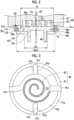
- the orbiting end plate 44 has a disk shape centered on the axis O2 of the eccentric shaft 8, and is attached to the eccentric shaft 8. As illustrated in Figs. 2 and 4 , the orbiting end plate 44 has a thick portion 44a that has a disk shape centered on the axis O2 of the eccentric shaft 8, and a flange-shaped thin portion 44b that is integrated with the thick portion 44a and protrudes outward in the radial direction from the thick portion 44a.
- the thick portion 44a is connected to the eccentric shaft 8 so as to be rotatable around the eccentric shaft 8. Specifically, a cylindrical part 46 that covers the eccentric shaft 8 from the outer circumference is integrally provided to the lower portion of the thick portion 44a. A bearing 46a is provided in the cylindrical part 46 as illustrated in Fig. 1 , and the thick portion 44a is rotated together with the cylindrical part 46 around the axis O2 of the eccentric shaft 8.
- the thin portion 44b has an annular shape centered on the axis O2 of the eccentric shaft 8.
- the thin portion 44b has a smaller thickness dimension in the directions of the axes O1 and O2 than the thick portion 44a, and is arranged at a position where the end face (upper surface) facing the fixed end plate 41 side is apart from the fixed end plate 41 as compared with the thick portion 44a.
- the orbiting end plate 44 has a surface facing the radial direction at the outer end portion in the radial direction, and a step is provided to the outer end portion of the orbiting end plate 44 in the radial direction.
- the orbiting end plate 44 is provided with a pair of orbiting-side key grooves 44c at intervals of 180 degrees in the circumferential direction.
- the orbiting-side key groove 44c is open on the outer peripheral surface of the thin portion 44b, and extends inward in the radial direction from the outer peripheral surface of the thin portion 44b to the thick portion 44a.
- the orbiting-side key groove 44c is provided between the thin portion 44b and the thick portion 44a.
- the orbiting-side key groove 44c penetrates the thin portion 44b in the direction of the axis O1, has the same dimension in the direction of the axis O1 as the thickness dimension of the thin portion 44b in the direction of the axis O1, and extends in the radial direction to the thick portion 44a.
- each orbiting-side key groove 44c is provided to enter the back side of the thick portion 44a.
- Each orbiting-side key groove 44c is formed such that the section orthogonal to the radial direction has a rectangular shape.
- Each orbiting-side key groove 44c has a pair of planar key sliding surfaces 44d which are disposed in parallel at intervals in the circumferential direction and extend along the direction of the axis O1 and the radial direction.
- a thrust plate 47 that receives a load in the direction of the axis O1 from the scroll compression portion 5, that is, a thrust load is provided between the orbiting end plate 44 and the scroll bearing 22.
- the thrust plate 47 has an annular shape to surround the axis O1 of the rotating shaft 2 as illustrated in Fig. 2 .
- the thrust plate 47 is provided between the thin portion 44b and the thick portion 44a. That is, at least a part of the thrust plate 47 is provided at a position that supports the thick portion 44a from below in the direction of the axis O1.
- the outer diameter of the thrust plate 47 is set as dout, and the outer diameter of the thick portion 44a is set as D, a relationship of din ⁇ D ⁇ dout is established.
- the orbiting wrap 45 is provided in an overlapping manner in the radial direction so as to face the fixed wrap 42 in the radial direction.
- a space between the orbiting wrap 45 and the fixed wrap 42 is the compression chamber C2 in which the refrigerant is compressed.
- the refrigerant that has flowed from the compression chamber C1 of the rotary compression portion 4 is introduced to the compression chamber C2 after passing around the motor 3 and through the scroll bearing 22.
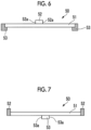
- the Oldham ring 50 has a ring body 51 that has an annular shape to surround the axis O1 of the rotating shaft 2, and a pair of fixed-side keys 52 and a pair of orbiting-side keys 53 that are provided to the ring body 51.
- the ring body 51 has a substantially constant thickness, that is, a substantially constant dimension in the direction of the axis O1.
- the ring body 51 is provided to be placed on the end face (upper surface) of the thin portion 44b of the orbiting end plate 44, the end face facing the fixed end plate 41 side.
- the front surface (upper surface) of the ring body 51 facing the fixed end plate 41 side is positioned above the front surface (upper surface) of the thick portion 44a facing the fixed end plate 41 side, so that a part of the ring body 51 is in a state of protruding upward from the thick portion 44a.
- a part of the ring body 51 which protrudes upward from the thick portion 44a is disposed in the annular groove 41b of the fixed end plate 41. Further, a fine gap SS is provided between the front surface (upper surface) of the ring body 51 facing the fixed end plate 41 side and the bottom surface of the annular groove 41b, so that the front surface of the ring body 51 and the bottom surface of the annular groove 41b are provided with an interval.
- the pair of fixed-side keys 52 are provided at intervals of 180 degrees in the circumferential direction, and are members which protrude upward from the front surface of the ring body 51 facing upward and have a rectangular section.
- Each fixed-side key 52 has the same dimension in the radial direction as the width dimension of the ring body 51 in the radial direction, and is integrally provided with the ring body 51 so as not to substantially protrude from the ring body 51 in the radial direction.
- the pair of fixed-side keys 52 are inserted to engage with the pair of fixed-side key grooves 41c provided to the fixed end plate 41, respectively.
- Each fixed-side key 52 has planar side surfaces 52a on both sides in the circumferential direction, and the side surfaces 52a slide with respect to the key sliding surfaces 41d of the fixed-side key groove 41c.
- the fixed-side key 52 is configured to reciprocate in the radial direction in the fixed-side key groove 41c.
- the pair of orbiting-side keys 53 are provided at intervals of 180 degrees in the circumferential direction, and are members which protrude downward from the front surface of the ring body 51 facing downward at positions shifted 90 degrees in the circumferential direction from the fixed-side keys 52 and have a rectangular section.
- Each orbiting-side key 53 has a larger dimension in the radial direction than the width dimension of the ring body 51 in the radial direction, and is integrally provided with the ring body 51 so as to protrude inward from the ring body 51 in the radial direction.
- the outer end face of each orbiting-side key 53 in the radial direction and the outer end face of the ring body 51 in the radial direction are disposed at substantially the same position.
- each orbiting-side key 53 is provided to the ring body 51 so as not to substantially protrude outward in the radial direction from the ring body 51.
- the pair of orbiting-side keys 53 are inserted to engage with the pair of orbiting-side key grooves 44c provided to the orbiting end plate 44, respectively.
- Each orbiting-side key 53 has planar side surfaces 53a on both sides in the circumferential direction, and the side surfaces 53a slide with respect to the key sliding surfaces 44d of the orbiting-side key groove 44c.
- the orbiting-side key 53 is configured to reciprocate in the radial direction in the orbiting-side key groove 44c.
- the orbiting scroll 43 orbits around the axis O1 of the rotating shaft 2 without rotating, and the refrigerant in the compression chamber C2 is compressed by the relative movement between the fixed wrap 42 and the orbiting wrap 45.
- the Oldham ring 50 is provided such that the ring body 51 protrudes in the direction of the axis O1 from the end face of the thick portion 44a facing the fixed end plate 41 side, and a part of the ring body 51 is disposed in the annular groove 41b of the fixed end plate 41. Therefore, even when the thickness dimension of the Oldham ring 50 in the direction of the axis O1 is increased in order to support high pressure and increase the capacity, the fixed end plate 41 can be disposed to be closer to the orbiting end plate 44. Thus, the scroll compression portion 5 can be made compact in the direction of the axis O1, and the entire scroll compressor 1 can be made compact.
- the lubricant When the lubricant is introduced to the scroll compression portion 5, the lubricant can be held in the annular groove 41b, the operation of the scroll compression portion 5 can be smoothed, and the efficiency can be further improved.
- the fixed-side key groove 41c is provided to extend from the annular groove 41b to the outer side of the annular groove 41b of the fixed end plate 41 in the radial direction. Therefore, in a case where the fixed-side key groove 41c is provided by drilling a hole in the fixed end plate 41 at a position on the outer side of the annular groove 41b in the radial direction and inserting an end mill into the hole, the machining start point of the end mill is formed in an arc shape following the outer shape of the drill.
- the key sliding surfaces 41d of the fixed-side key groove 41c can be formed in a planar shape along the radial direction in the annular groove 41b. Therefore, the key sliding surfaces 41d having a planar shape can be easily formed in the annular groove 41b.
- the thickness of the fixed end plate 41 in the direction of the axis O1 is larger than the thickness in the direction of the axis O1 at the position where the annular groove 41b is formed. Therefore, even when the fixed-side key groove is formed to extend to the outer side of the annular groove 41b in the radial direction, a problem in strength is unlikely to occur.
- the bottom surface of the annular groove 41b and the front surface of the ring body 51 are provided with an interval in the direction of the axis O1. Therefore, during the operation of the scroll compressor 1, the front surface of the ring body 51 is less likely to come into contact with the bottom surface of the annular groove 41b. Thus, the friction loss between the Oldham ring 50 and the fixed end plate 41 can be reduced.
- the orbiting end plate 44 of the orbiting scroll 43 has the thick portion 44a and the thin portion 44b. Further, the thin portion 44b is provided on the outer side of the orbiting end plate 44 in the radial direction. Therefore, the weight of the outer end portion of the orbiting end plate 44 in the radial direction can be reduced, and the moment of inertia when the orbiting end plate 44 orbits around the axis O1 of the rotating shaft 2 can be reduced. Thus, even if the orbiting end plate 44 is enlarged in order to support high pressure and increase the capacity of the scroll compressor 1, the vibration can be suppressed. As a result, it is possible to improve the efficiency while supporting high pressure and increasing the capacity of the scroll compressor 1.
- the outer end portion of the orbiting end plate 44 in the radial direction is less affected by the compressive load than the central portion of the orbiting end plate 44. Therefore, even when the thin portion 44b is provided to the orbiting end plate 44, a problem in strength is unlikely to occur.
- the thrust plate 47 is provided at a position that supports the thick portion 44a of the orbiting end plate 44, so that the thick portion 44a that receives many thrust loads due to the compressive load can be supported by the thrust plate 47.
- the load does not act only on the thin portion 44b, and it is possible to sufficiently cope with the compressive load.
- the orbiting-side key groove 44c is provided over the thin portion 44b and the thick portion 44a of the orbiting end plate 44, so that the length dimension of the orbiting-side key 53 in the radial direction can be increased. Accordingly, the surface pressure of the side surfaces 53a of the orbiting-side key 53, which slide with respect to the key sliding surfaces 44d of the orbiting-side key groove 44c, can be reduced, and the strength of the Oldham ring 50 can be improved.
- the orbiting-side key groove 44c extends to the thick portion 44a, but the thickness dimension of the thick portion 44a in the direction of the axis O1 is larger than that of the thin portion 44b, and thus a problem in strength is unlikely to occur.
- the ring body 51 of the Oldham ring 50 may have a dimension so as not to protrude upward in the direction of the axis O1 from the thick portion 44a.
- the orbiting-side key groove 44c may be formed only on the thin portion 44b.
- the fixed-side key groove may be formed only in the annular groove.
Landscapes
- Engineering & Computer Science (AREA)
- Mechanical Engineering (AREA)
- General Engineering & Computer Science (AREA)
- Rotary Pumps (AREA)
- Applications Or Details Of Rotary Compressors (AREA)
Claims (3)
- Spiralverdichter (1), umfassend:eine Drehwelle (2), die sich entlang einer Achse (01) erstreckt;einen Motor (3), der die Drehwelle (2) dreht;einen Spiralverdichtungsabschnitt (5), der durch die Drehung der Drehwelle (2) ein Kältemittel verdichtet; undein Gehäuse (6), das die Drehwelle (2), den Motor (3) und den Spiralverdichtungsabschnitt (5) aufnimmt,wobei der Spiralverdichtungsabschnitt (5) Folgendes beinhalteteine feststehende Spirale (40), die eine feststehende Endplatte (41) aufweist, die an dem Gehäuse (6) befestigt ist, und eine feststehende Windung (42), die von der feststehenden Endplatte in Richtung der Achse (01) hervorsteht,eine umlaufende Spirale (43), die an der Drehwelle (2) bereitgestellt ist und eine umlaufende Endplatte (44) aufweist, die angeordnet ist, um der feststehenden Endplatte (41) in Richtung der Achse (01) zugewandt zu sein, und eine umlaufende Windung (45), die von der umlaufenden Endplatte in Richtung der feststehenden Endplatte hervorsteht und zusammen mit der feststehenden Windung (42) eine Kompressionskammer (C1, C2) für das Kältemittel bildet, undeinen Oldham-Ring (50), der die umlaufende Spirale (43) trägt, sodass die umlaufende Spirale (43) ohne zu drehen um die Achse (01) umläuft,wobei der Oldham-Ring (50) Folgendes aufweisteinen Ringkörper (51), der eine ringförmige Form aufweist, um die Achse (01) zu umgeben, undeine Vielzahl von Passfedern (52, 53), die von dem Ringkörper (51) hervorstehen und in Passnuten (44c, 41c) eingesetzt sind, die in der umlaufenden Endplatte (44) und der feststehenden Endplatte (41) bereitgestellt sind,wobei die feststehende Endplatte (41) eine ringförmige Nut (41b) aufweist, die an einer Außenseite der feststehenden Windung (42) in einer radialen Richtung angeordnet ist, eine ringförmige Form um die Achse (01) aufweist und in einer Richtung weg von der umlaufenden Endplatte (44) in Richtung der Achse vertieft ist, undwobei die umlaufende Endplatte (44) einen dicken Abschnitt (44a), der eine Scheibenform aufweist und mit der umlaufenden Windung (45) versehen ist, und einen dünnen Abschnitt (44b), der integral mit dem dicken Abschnitt (44a) bereitgestellt ist, aufweist, wobei der Ringkörper (51) bereitgestellt ist, um auf der Endfläche des dünnen Abschnitts (44b) angeordnet zu sein, und ein Teil des Ringkörpers (51) in der ringförmigen Nut (41b) angeordnet ist,wobei der Spiralverdichter (1) dadurch gekennzeichnet ist, dass der Oldham-Ring (50) zwischen die feststehende Endplatte (41) und die umlaufende Endplatte (44) eingefügt ist, und dass der dünne Abschnitt (44b) der umlaufenden Endplatte an einer Außenseite des dicken Abschnitts (44a) in einer radialen Richtung bereitgestellt ist, eine ringförmige Form aufweist und eine kleinere Dickenabmessung in Richtung der Achse (01) als eine Dickenabmessung des dicken Abschnitts (44a) aufweist, und wovon eine Endfläche, die der Seite der feststehenden Endplatte (41) zugewandt ist, an einer Position weg von der feststehenden Endplatte (41) im Vergleich zu dem dicken Abschnitt (44a) angeordnet ist.
- Spiralverdichter (1) nach Anspruch 1,
wobei die Passnut (41c) in der feststehenden Endplatte (41) von der ringförmigen Nut (41b) in der Richtung weg von der umlaufenden Endplatte (44) in Richtung der Achse (01) zurückgesetzt ist und bereitgestellt ist, um sich von der ringförmigen Nut (41b) in der radialen Richtung zu einer Außenseite der ringförmigen Nut (41b) zu erstrecken. - Spiralverdichter nach Anspruch 1 oder 2,
wobei eine Bodenfläche der ringförmigen Nut (41b) und die vordere Fläche des Ringkörpers mit einem Abstand (SS) in Richtung der Achse (01) bereitgestellt sind.
Applications Claiming Priority (1)
| Application Number | Priority Date | Filing Date | Title |
|---|---|---|---|
| PCT/JP2019/016826 WO2020213155A1 (ja) | 2019-04-19 | 2019-04-19 | スクロール圧縮機 |
Publications (4)
| Publication Number | Publication Date |
|---|---|
| EP3936724A1 EP3936724A1 (de) | 2022-01-12 |
| EP3936724A4 EP3936724A4 (de) | 2022-03-30 |
| EP3936724C0 EP3936724C0 (de) | 2024-10-23 |
| EP3936724B1 true EP3936724B1 (de) | 2024-10-23 |
Family
ID=72837169
Family Applications (1)
| Application Number | Title | Priority Date | Filing Date |
|---|---|---|---|
| EP19925324.6A Active EP3936724B1 (de) | 2019-04-19 | 2019-04-19 | Spiralverdichter |
Country Status (3)
| Country | Link |
|---|---|
| EP (1) | EP3936724B1 (de) |
| JP (1) | JP7208364B2 (de) |
| WO (1) | WO2020213155A1 (de) |
Family Cites Families (8)
| Publication number | Priority date | Publication date | Assignee | Title |
|---|---|---|---|---|
| JP2002235679A (ja) * | 2001-02-09 | 2002-08-23 | Mitsubishi Heavy Ind Ltd | スクロール圧縮機 |
| JP2009030514A (ja) * | 2007-07-26 | 2009-02-12 | Denso Corp | スクロール型圧縮機 |
| KR101718038B1 (ko) * | 2010-12-29 | 2017-03-20 | 엘지전자 주식회사 | 스크롤 압축기 |
| CN102235355A (zh) * | 2011-07-27 | 2011-11-09 | 安徽美芝压缩机有限公司 | 涡旋压缩机 |
| KR101216466B1 (ko) * | 2011-10-05 | 2012-12-31 | 엘지전자 주식회사 | 올담링을 갖는 스크롤 압축기 |
| JP5459376B1 (ja) * | 2012-09-28 | 2014-04-02 | ダイキン工業株式会社 | スクロール圧縮機 |
| FR3000143B1 (fr) * | 2012-12-21 | 2018-11-09 | Danfoss Commercial Compressors | Compresseur a spirales ayant des premier et second joints de oldham |
| US10400770B2 (en) * | 2016-02-17 | 2019-09-03 | Emerson Climate Technologies, Inc. | Compressor with Oldham assembly |
-
2019
- 2019-04-19 EP EP19925324.6A patent/EP3936724B1/de active Active
- 2019-04-19 WO PCT/JP2019/016826 patent/WO2020213155A1/ja not_active Ceased
- 2019-04-19 JP JP2021514771A patent/JP7208364B2/ja active Active
Also Published As
| Publication number | Publication date |
|---|---|
| WO2020213155A1 (ja) | 2020-10-22 |
| EP3936724C0 (de) | 2024-10-23 |
| EP3936724A4 (de) | 2022-03-30 |
| EP3936724A1 (de) | 2022-01-12 |
| JPWO2020213155A1 (de) | 2020-10-22 |
| JP7208364B2 (ja) | 2023-01-18 |
Similar Documents
| Publication | Publication Date | Title |
|---|---|---|
| KR101342409B1 (ko) | 키 커플링 및 스크롤 압축기 | |
| US10221852B2 (en) | Multi stage scroll vacuum pumps and related scroll devices | |
| US4734020A (en) | Scroll type compressor with spiral oil feeding grooves in thrust bearing | |
| US20130209305A1 (en) | Scroll compressor | |
| US20200158109A1 (en) | Scroll compressor | |
| CN101952552A (zh) | 非对称键联轴器接触件和具有该接触件的涡旋压缩机 | |
| US7549851B2 (en) | Rotary fluid machine having a pair of rotation mechanisms and a partition plate disposed between the rotation mechanisms | |
| US20200080557A1 (en) | Motor-operated compressor | |
| US20090098000A1 (en) | Scroll compressor with scroll deflection compensation | |
| KR20020034883A (ko) | 복수 실린더 로터리 압축기 | |
| CN101319672A (zh) | 涡旋压缩机 | |
| JP2009047040A (ja) | スクロール型流体機械 | |
| US11231035B2 (en) | Scroll compressor | |
| EP3936723B1 (de) | Spiralverdichter | |
| US20110076169A1 (en) | Rotary compressor | |
| EP3936724B1 (de) | Spiralverdichter | |
| EP3633197B1 (de) | Spiralverdichter | |
| JP2609839B2 (ja) | スクロール型圧縮装置 | |
| US20060073056A1 (en) | Hermetically sealed type orbiting vane compressor | |
| KR20010064538A (ko) | 스크롤 압축기의 고저압 분리구조 | |
| US20060177336A1 (en) | Dual-piston valve for orbiting vane compressors | |
| US12473917B2 (en) | Scroll assemblies and compressors including the same | |
| US20250354553A1 (en) | Scroll compressor | |
| JP4013992B2 (ja) | スクロール型流体機械 | |
| JP3976070B2 (ja) | スクロール型流体機械 |
Legal Events
| Date | Code | Title | Description |
|---|---|---|---|
| STAA | Information on the status of an ep patent application or granted ep patent |
Free format text: STATUS: THE INTERNATIONAL PUBLICATION HAS BEEN MADE |
|
| PUAI | Public reference made under article 153(3) epc to a published international application that has entered the european phase |
Free format text: ORIGINAL CODE: 0009012 |
|
| STAA | Information on the status of an ep patent application or granted ep patent |
Free format text: STATUS: REQUEST FOR EXAMINATION WAS MADE |
|
| 17P | Request for examination filed |
Effective date: 20211007 |
|
| AK | Designated contracting states |
Kind code of ref document: A1 Designated state(s): AL AT BE BG CH CY CZ DE DK EE ES FI FR GB GR HR HU IE IS IT LI LT LU LV MC MK MT NL NO PL PT RO RS SE SI SK SM TR |
|
| A4 | Supplementary search report drawn up and despatched |
Effective date: 20220228 |
|
| RIC1 | Information provided on ipc code assigned before grant |
Ipc: F04C 29/00 20060101ALI20220222BHEP Ipc: F01C 21/00 20060101ALI20220222BHEP Ipc: F01C 17/06 20060101ALI20220222BHEP Ipc: F04C 18/02 20060101AFI20220222BHEP |
|
| DAV | Request for validation of the european patent (deleted) | ||
| DAX | Request for extension of the european patent (deleted) | ||
| GRAP | Despatch of communication of intention to grant a patent |
Free format text: ORIGINAL CODE: EPIDOSNIGR1 |
|
| STAA | Information on the status of an ep patent application or granted ep patent |
Free format text: STATUS: GRANT OF PATENT IS INTENDED |
|
| RIC1 | Information provided on ipc code assigned before grant |
Ipc: F04C 29/00 20060101ALI20240505BHEP Ipc: F01C 21/00 20060101ALI20240505BHEP Ipc: F01C 17/06 20060101ALI20240505BHEP Ipc: F04C 18/02 20060101AFI20240505BHEP |
|
| INTG | Intention to grant announced |
Effective date: 20240523 |
|
| RAP3 | Party data changed (applicant data changed or rights of an application transferred) |
Owner name: MITSUBISHI HEAVY INDUSTRIES THERMAL SYSTEMS, LTD. |
|
| GRAS | Grant fee paid |
Free format text: ORIGINAL CODE: EPIDOSNIGR3 |
|
| GRAA | (expected) grant |
Free format text: ORIGINAL CODE: 0009210 |
|
| STAA | Information on the status of an ep patent application or granted ep patent |
Free format text: STATUS: THE PATENT HAS BEEN GRANTED |
|
| AK | Designated contracting states |
Kind code of ref document: B1 Designated state(s): AL AT BE BG CH CY CZ DE DK EE ES FI FR GB GR HR HU IE IS IT LI LT LU LV MC MK MT NL NO PL PT RO RS SE SI SK SM TR |
|
| REG | Reference to a national code |
Ref country code: GB Ref legal event code: FG4D |
|
| REG | Reference to a national code |
Ref country code: CH Ref legal event code: EP |
|
| REG | Reference to a national code |
Ref country code: DE Ref legal event code: R096 Ref document number: 602019060974 Country of ref document: DE |
|
| REG | Reference to a national code |
Ref country code: IE Ref legal event code: FG4D |
|
| U01 | Request for unitary effect filed |
Effective date: 20241031 |
|
| U07 | Unitary effect registered |
Designated state(s): AT BE BG DE DK EE FI FR IT LT LU LV MT NL PT RO SE SI Effective date: 20241112 |
|
| PG25 | Lapsed in a contracting state [announced via postgrant information from national office to epo] |
Ref country code: HR Free format text: LAPSE BECAUSE OF FAILURE TO SUBMIT A TRANSLATION OF THE DESCRIPTION OR TO PAY THE FEE WITHIN THE PRESCRIBED TIME-LIMIT Effective date: 20241023 Ref country code: IS Free format text: LAPSE BECAUSE OF FAILURE TO SUBMIT A TRANSLATION OF THE DESCRIPTION OR TO PAY THE FEE WITHIN THE PRESCRIBED TIME-LIMIT Effective date: 20250223 |
|
| U20 | Renewal fee for the european patent with unitary effect paid |
Year of fee payment: 7 Effective date: 20250310 |
|
| PG25 | Lapsed in a contracting state [announced via postgrant information from national office to epo] |
Ref country code: ES Free format text: LAPSE BECAUSE OF FAILURE TO SUBMIT A TRANSLATION OF THE DESCRIPTION OR TO PAY THE FEE WITHIN THE PRESCRIBED TIME-LIMIT Effective date: 20241023 |
|
| PG25 | Lapsed in a contracting state [announced via postgrant information from national office to epo] |
Ref country code: NO Free format text: LAPSE BECAUSE OF FAILURE TO SUBMIT A TRANSLATION OF THE DESCRIPTION OR TO PAY THE FEE WITHIN THE PRESCRIBED TIME-LIMIT Effective date: 20250123 |
|
| PG25 | Lapsed in a contracting state [announced via postgrant information from national office to epo] |
Ref country code: GR Free format text: LAPSE BECAUSE OF FAILURE TO SUBMIT A TRANSLATION OF THE DESCRIPTION OR TO PAY THE FEE WITHIN THE PRESCRIBED TIME-LIMIT Effective date: 20250124 |
|
| PG25 | Lapsed in a contracting state [announced via postgrant information from national office to epo] |
Ref country code: PL Free format text: LAPSE BECAUSE OF FAILURE TO SUBMIT A TRANSLATION OF THE DESCRIPTION OR TO PAY THE FEE WITHIN THE PRESCRIBED TIME-LIMIT Effective date: 20241023 |
|
| PG25 | Lapsed in a contracting state [announced via postgrant information from national office to epo] |
Ref country code: RS Free format text: LAPSE BECAUSE OF FAILURE TO SUBMIT A TRANSLATION OF THE DESCRIPTION OR TO PAY THE FEE WITHIN THE PRESCRIBED TIME-LIMIT Effective date: 20250123 |
|
| PG25 | Lapsed in a contracting state [announced via postgrant information from national office to epo] |
Ref country code: SM Free format text: LAPSE BECAUSE OF FAILURE TO SUBMIT A TRANSLATION OF THE DESCRIPTION OR TO PAY THE FEE WITHIN THE PRESCRIBED TIME-LIMIT Effective date: 20241023 |
|
| PG25 | Lapsed in a contracting state [announced via postgrant information from national office to epo] |
Ref country code: SK Free format text: LAPSE BECAUSE OF FAILURE TO SUBMIT A TRANSLATION OF THE DESCRIPTION OR TO PAY THE FEE WITHIN THE PRESCRIBED TIME-LIMIT Effective date: 20241023 |
|
| PG25 | Lapsed in a contracting state [announced via postgrant information from national office to epo] |
Ref country code: CZ Free format text: LAPSE BECAUSE OF FAILURE TO SUBMIT A TRANSLATION OF THE DESCRIPTION OR TO PAY THE FEE WITHIN THE PRESCRIBED TIME-LIMIT Effective date: 20241023 |
|
| PLBE | No opposition filed within time limit |
Free format text: ORIGINAL CODE: 0009261 |
|
| STAA | Information on the status of an ep patent application or granted ep patent |
Free format text: STATUS: NO OPPOSITION FILED WITHIN TIME LIMIT |
|
| 26N | No opposition filed |
Effective date: 20250724 |
|
| REG | Reference to a national code |
Ref country code: CH Ref legal event code: H13 Free format text: ST27 STATUS EVENT CODE: U-0-0-H10-H13 (AS PROVIDED BY THE NATIONAL OFFICE) Effective date: 20251125 |
|
| PG25 | Lapsed in a contracting state [announced via postgrant information from national office to epo] |
Ref country code: MC Free format text: LAPSE BECAUSE OF FAILURE TO SUBMIT A TRANSLATION OF THE DESCRIPTION OR TO PAY THE FEE WITHIN THE PRESCRIBED TIME-LIMIT Effective date: 20241023 |
|
| PG25 | Lapsed in a contracting state [announced via postgrant information from national office to epo] |
Ref country code: CH Free format text: LAPSE BECAUSE OF NON-PAYMENT OF DUE FEES Effective date: 20250430 |
|
| PGFP | Annual fee paid to national office [announced via postgrant information from national office to epo] |
Ref country code: GB Payment date: 20260313 Year of fee payment: 8 |
|
| PG25 | Lapsed in a contracting state [announced via postgrant information from national office to epo] |
Ref country code: IE Free format text: LAPSE BECAUSE OF NON-PAYMENT OF DUE FEES Effective date: 20250419 |
|
| U20 | Renewal fee for the european patent with unitary effect paid |
Year of fee payment: 8 Effective date: 20260310 |