EP3936282A1 - Powered fastener driver - Google Patents
Powered fastener driver Download PDFInfo
- Publication number
- EP3936282A1 EP3936282A1 EP21184108.5A EP21184108A EP3936282A1 EP 3936282 A1 EP3936282 A1 EP 3936282A1 EP 21184108 A EP21184108 A EP 21184108A EP 3936282 A1 EP3936282 A1 EP 3936282A1
- Authority
- EP
- European Patent Office
- Prior art keywords
- piston
- cylinder
- dead
- center position
- pressure
- Prior art date
- Legal status (The legal status is an assumption and is not a legal conclusion. Google has not performed a legal analysis and makes no representation as to the accuracy of the status listed.)
- Pending
Links
Images


Classifications
-
- B—PERFORMING OPERATIONS; TRANSPORTING
- B25—HAND TOOLS; PORTABLE POWER-DRIVEN TOOLS; MANIPULATORS
- B25C—HAND-HELD NAILING OR STAPLING TOOLS; MANUALLY OPERATED PORTABLE STAPLING TOOLS
- B25C1/00—Hand-held nailing tools; Nail feeding devices
- B25C1/04—Hand-held nailing tools; Nail feeding devices operated by fluid pressure, e.g. by air pressure
- B25C1/041—Hand-held nailing tools; Nail feeding devices operated by fluid pressure, e.g. by air pressure with fixed main cylinder
- B25C1/042—Main valve and main cylinder
-
- B—PERFORMING OPERATIONS; TRANSPORTING
- B25—HAND TOOLS; PORTABLE POWER-DRIVEN TOOLS; MANIPULATORS
- B25C—HAND-HELD NAILING OR STAPLING TOOLS; MANUALLY OPERATED PORTABLE STAPLING TOOLS
- B25C1/00—Hand-held nailing tools; Nail feeding devices
- B25C1/04—Hand-held nailing tools; Nail feeding devices operated by fluid pressure, e.g. by air pressure
- B25C1/047—Mechanical details
-
- B—PERFORMING OPERATIONS; TRANSPORTING
- B25—HAND TOOLS; PORTABLE POWER-DRIVEN TOOLS; MANIPULATORS
- B25C—HAND-HELD NAILING OR STAPLING TOOLS; MANUALLY OPERATED PORTABLE STAPLING TOOLS
- B25C1/00—Hand-held nailing tools; Nail feeding devices
- B25C1/06—Hand-held nailing tools; Nail feeding devices operated by electric power
Definitions
- the present invention relates to power tools, and more particularly to powered fastener drivers.
- fastener drivers used to drive fasteners (e.g., nails, tacks, staples, etc.) into a workpiece known in the art.
- fastener drivers operate utilizing various energy sources (e.g., compressed air generated by an air compressor, electrical energy, flywheel mechanisms) known in the art, but often these designs are met with power, size, and cost constraints.
- the invention provides, in a first aspect, a powered fastener driver including a cylinder and a piston positioned within the cylinder.
- the piston being moveable between a top-dead-center position and a bottom-dead-center position.
- the piston having a non-circular shape.
- the piston has a kidney-bean shape.
- the piston is a compressor piston that is driven between the top-dead-center position and the bottom-dead-center position by a reciprocating mechanism.
- the cylinder is a first cylinder
- the piston is a first piston
- the powered fastener driver further comprises: a second cylinder in selective fluid communication with the first cylinder, a second piston positioned within the second cylinder, the second piston being moveable between a top-dead-center position and a bottom-dead-center position, and a drive blade coupled to the second piston for movement therewith.
- the second piston has a different shape than the first piston.
- the first piston only partially wraps around the second piston.
- the powered fastener driver further comprises a reciprocating mechanism configured to drive the first piston between the top-dead-center position and the bottom-dead-center position, the second piston is driven from the top-dead-center position to the bottom-dead-center position in response to the movement of the first piston.
- the powered fastener driver further comprises: a pressure storage chamber in selective fluid communication with the first cylinder, and a pressure valve positioned between the pressure storage chamber and the second cylinder.
- the pressure valve is configured to move from a closed position to an open position in response to the pressure within the pressure storage chamber reaching a threshold pressure.
- a powered fastener driver including a first cylinder, a first piston positioned within the first cylinder, the first piston being moveable between a top-dead-center position and a bottom-dead-center position, a pressure storage chamber in fluid communication with the first cylinder, a second cylinder in selective fluid communication with the pressure storage chamber, a second piston positioned within the second cylinder, the second piston being moveable between a top-dead-center position and a bottom-dead-center position to initiate a fastener driving operation, a drive blade coupled to the second piston for movement therewith, and a pressure valve positioned between the pressure storage chamber and the second cylinder.
- the pressure valve is configured to move from a closed position to an open position in response to the pressure within the pressure storage chamber reaching a threshold pressure.
- the powered fastener driver further comprises: a reciprocating mechanism configured to drive the first piston between the top-dead-center position and the bottom-dead-center position, the second piston is driven from the top-dead-center position to the bottom-dead-center position in response to the movement of the first piston.
- the powered fastener driver further comprises: a pressure sensor positioned within the pressure storage chamber, the pressure sensor is electronically coupled to a control system of the powered fastener driver.
- the pressure valve is a solenoid-actuated valve
- the pressure detected within the pressure storage chamber by the pressure sensor is utilized by the control system to determine when to energize the solenoid-actuated valve.
- the powered fastener driver further comprises: a first check valve positioned between the first cylinder and the pressure storage chamber, the first check valve is configured to open to permit air flow into the pressure storage chamber from the first cylinder.
- the powered fastener driver further comprises: a second check valve positioned between the first and second cylinders, the second check valve is configured to open to permit air to flow into the first cylinder from the second cylinder.
- the second piston includes a magnetic latch that interacts with an annular magnet positioned near the second cylinder to hold the second piston in the top-dead-center position.
- the first piston has a non-circular shape.
- a powered fastener driver including a first cylinder, a first piston positioned within the first cylinder, the first piston being moveable between a top-dead-center position and a bottom-dead-center position, a second cylinder in selective fluid communication with the first cylinder, a second piston positioned within the second cylinder, the second piston being moveable between a top-dead-center position and a bottom-dead-center position to initiate a fastener driving operation, a drive blade coupled to the second piston for movement therewith, and a check valve positioned between the second cylinder and the first cylinder, the check valve is configured to open to permit air to flow into the first cylinder from the second cylinder.
- the powered fastener driver further comprises: a pressure storage chamber in selective fluid communication with the first cylinder, and a first check valve positioned between the first cylinder and the pressure storage chamber, the first check valve is configured to open to permit air flow into the pressure storage chamber from the first cylinder, and the check valve is a second valve.
- the powered fastener driver further comprises: a reciprocating mechanism configured to drive the first piston between the top-dead-center position and the bottom-dead-center position, the second piston is driven from the top-dead-center position to the bottom-dead-center position in response to the movement of the first piston.
- the first piston has a non-circular shape.
- a powered fastener driver 10 is operable to drive fasteners (e.g., nails, tacks, staples, etc.) held within a magazine 14 into a workpiece.
- the powered fastener driver 10 includes an outer housing with a handle portion, and a user-actuated trigger 26 mounted on the handle portion.
- the powered fastener driver 10 does not require an external source of air pressure, but rather the powered fastener driver 10 includes an on-board air compressor 30. In this way, the weight and/or size of tool may be reduced.
- the on-board air compressor 30 is powered by a power source (e.g., a battery pack), coupled to a battery attachment portion of the outer housing.
- the powered fastener driver 10 includes a drive blade 34 actuated by the on-board air compressor 30 to drive the fasteners into a workpiece.
- the compressor 30 includes a compressor cylinder 38 and a compressor piston 42 in the compressor cylinder 38 driven in a reciprocating manner by a reciprocating mechanism including a motor 46, a transmission 50, and a crank arm assembly 54.
- the powered fastener driver 10 also includes a drive cylinder 58 and a drive piston 62 slidably disposed in the drive cylinder 58.
- the drive piston 62 is movable between a top-dead-center position ( FIG. 8A ) and a bottom-dead-center position ( FIG. 8H ).
- the compressor piston 42 is moveable between a top-dead-center position ( FIG. 8B ) and a bottom-dead-center position ( FIG. 8A ).
- the smaller drive cylinder 58 at least partially extends into the larger compressor cylinder 38.
- the compressor piston 42 does not surround the entire drive cylinder 58. Instead, the compressor piston 42 is kidney-shaped (i.e., bean-shaped) and only partially wraps around the drive cylinder 58.
- the compressor piston 42 therefore, has a different shape than the drive piston 62.
- the compressor piston 42 is not circular, but rather is non-circularly shaped.
- the compressor piston 42 includes an outer convex surface 66, an inner concave surface 70, and rounded ends 74 connecting the outer surface 66 with the inner surface 70 ( FIG. 5 ).
- the size and/or weight of the fastener driver 10 may be advantageously reduced for improved handling, manufacturability, and/or the like.
- the compressor piston 42 defines a surface area 78, and if an equivalent surface area was reconfigured as a traditional circular piston, illustrated as a dashed circle 82 in FIG. 5 , the size of the tool would be increased.
- the overall size of the on-board compressor 30, and thus the fastener driver 10 is reduced.
- the volume compressed by a single stroke of the compressor piston 42 is approximately 0.000107 cubic meters (6.5 cubic inches) and achieves a compression ratio of approximately 5.3:1 per stroke.
- the on-board air compressor 30 includes a head assembly 86 positioned at a top end of the cylinders 38, 58.
- the head assembly 86 includes an end cap 90, a first portion 94 of which is positioned within the compressor cylinder 38 and a second portion 98 of which is positioned within the drive cylinder 58.
- a pressure storage chamber 102 is formed within the head assembly 86. As explained in greater detail below, the pressure storage chamber 102 is capable of fluidly communicating with the compressor cylinder 38 and the drive cylinder 58.
- the first portion 94 of the head assembly 86 includes a first passageway 106 that fluidly communicates the compressor cylinder 38 and the pressure storage chamber 102.
- a first check valve 110 is positioned within the first passageway 106 between the compressor cylinder 38 and the pressure storage chamber 102.
- the first check valve 110 is a one-way valve that permits air to flow into the pressure storage chamber 102 from the compressor cylinder 38, but does not permit air to flow into the compressor cylinder 38 from the pressure storage chamber 102.
- the first check valve 110 includes a ball 114 that is biased by a compression spring 118 into a seat 122 around the first passageway 106. As explained in greater detail below, compressed air created by the compressor piston 42 unseats the ball 114 from the seat 122 and flows into the pressure storage chamber 102. During other times, the spring 118 biases the ball 114 into the seat 122 to seal the pressure storage chamber 102 from the compressor cylinder 38.
- a pressure sensor 126 is partially positioned within the pressure storage chamber 102 and is configured to detect a pressure level within the pressure storage chamber 102.
- the pressure sensor 126 is electrically coupled to a control system (i.e., a controller).
- a control system i.e., a controller
- the pressure detected within the pressure storage chamber 102 by the pressure sensor 126 is utilized by the controller to determine when to de-energize the motor 46.
- the pressure detected within the pressure storage chamber 102 by the pressure sensor 126 is utilized by the controller to determine when to energize a solenoid-actuated pressure valve that communicates the pressure storage chamber 102 with the drive cylinder 58.
- the head assembly 86 includes a passageway 130 in which to receive a portion of the pressure sensor 126.
- the passageway 130 extends between the pressure storage chamber 102 and the exterior of the head assembly 86.
- a pressure valve 134 (i.e., a pressure release valve, a firing valve, and/or the like) is positioned within the head assembly 86 and selectively fluidly communicates the pressure storage chamber 102 with the drive cylinder 58.
- the pressure valve 134 may be an electrically actuated valve or a pressure-actuated valve (i.e., a valve that is responsive to external forces applied by the compressed air in the pressure storage chamber 102).
- the pressure valve 134 remains in a closed position ( FIG. 7A ) as the pressure within the pressure storage chamber 102 increases.
- the pressure valve 134 moves to an open position ( FIG. 7B ).
- the pressure valve 134 When the pressure valve 134 is in the open position, the pressure within the pressure storage chamber 102 is fluidly communicated to the drive cylinder 58. As described in further detail below, when the pressure valve 134 opens, the pressure within the pressure storage chamber 102 moves the drive piston 62 toward a bottom-dead-center position causing a fastener to be driven into a workpiece by the drive blade 34.
- the pressure valve 134 is illustrated as a pressure-actuated release valve.
- the pressure valve 134 includes a plunger 138 with a first surface 142 and a second surface 146.
- the first surface 142 is opposite of (i.e., in facing relationship to) the second surface 146.
- the first surface 142 is larger than the second surface 146.
- the first surface 142 and the second surface 146 are in fluid communication with the pressure storage chamber 102.
- the first surface 142 and the second surface 146 partially define the pressure storage chamber 102.
- a spring 150 biases the plunger 138 into a first position ( FIG. 7A ) in which the pressure storage chamber 102 is sealed from the drive cylinder 58 by a sealing plate 162.
- the plunger 138 When the pressure within the pressure storage chamber 102 reaches a threshold pressure value (i.e., a firing pressure), the plunger 138 is caused to automatically move to a second position ( FIG. 7B ) in which the pressure storage chamber 102 is fluidly communicated with the drive cylinder 58. More specifically, when the pressure in the pressure storage chamber 102 is at or below the threshold, a force 154 acting upward (as viewed in FIG. 7A ) on the first surface 142 and a force 158 acting downward (as viewed in FIG. 7A ) on the second surface 146 are approximately the same and essentially cancel each other out. As a result of the approximately equal forces 154, 158, the bias force of the spring 150 keeps the plunger 138 in the closed position.
- a threshold pressure value i.e., a firing pressure
- the force 154 acting on the first surface 142 is much larger than the force 158 acting on the second surface 146.
- the first surface 142 is larger than the second surface 146 so the force acting on the first surface 142 is larger when both surfaces 142, 146 are acted upon by the threshold pressure value.
- the difference in force acting on the first surface 142 and the force acting on the second surface 146 causes the plunger 138 to move (e.g., slide, translate, and/or the like) against the bias of the spring 150 into the open position ( FIG. 7B ).
- the pressure from the pressure storage chamber 102 surrounds the sealing plate 162 of the plunger 138 so that the pressure is no longer creating a net force acting on the second surface 146.
- the plunger 138 will quickly move to the open position once the bottom sealing plate 162 of the plunger 138 has been unseated.
- the plunger 138 may remain in the open position until the pressure drops and the spring 150 biases the plunger 138 back into the seated, closed position.
- the threshold pressure value at which the pressure valve 134 moves from the closed position ( FIG. 7A ) to the open position ( FIG. 7B ) can be adjusted or controlled by the design of the difference in surface area of the first surface 142 and the second surface 146, and with the stiffness of the spring 150. In this way, the amount of pressure acting on the drive piston 62 may be increased or decreased for driving different sizes of fasteners (e.g., 16 gauge nails, 18 gauge nails, and/or the like) to appropriate distances within a workpiece. In this way, the fastener driver 10 may be suitable for use in a variety of different fastening applications.
- fasteners e.g. 16 gauge nails, 18 gauge nails, and/or the like
- a plunger with a first surface that is two times the size of the second surface will move to an open position at a lower threshold pressure value than a plunger with a surface 1.5 times the size of the second surface.
- a stiffer spring will cause the plunger to move open at a higher threshold pressure value.
- the pressure valve is an electronically controlled solenoid valve that is actuated between an open position (fluidly communicating the drive cylinder 58 with the pressure storage chamber 102) and a closed position (sealing the drive cylinder 58 from the pressure storage chamber 102).
- the first surface 142 of the plunger is equal to the second surface 146, and the plunger is actuated by the electrical actuator.
- the output from the pressure sensor 126 is utilized by the controller to determine when to actuate the solenoid and open the pressure valve.
- the drive piston 62 includes a body 166 and a ferromagnetic cap 170 is secured to the body 166 by a threaded fastener 174.
- the drive blade 34 may be attached to the main body 166 of the drive piston 62 by a pin 178 interference-fit to the main body 166.
- a magnetic latch 182 may be capable of holding the drive piston 62 in the top-dead-center position by way of a magnetic force.
- the latch 182 may include an annular magnet 186 positioned near the top of the drive cylinder 58.
- the annular magnet 186 may emit a magnetic field that magnetically attracts the ferromagnetic cap 170, which is also a part of the magnetic latch 182.
- the magnetic latch 182 could include a ferromagnetic portion positioned near the top of the drive cylinder 58 and a magnet secured to the drive piston 62.
- a second check valve 190 may be positioned within a cutout 194 formed between a sidewall 198 of the compressor cylinder 38 and a sidewall 202 of the drive cylinder 58.
- the second check valve 190 may be a one-way valve the permits air to flow into the compressor cylinder 38 from the drive cylinder 58, but does not permit air to flow into the drive cylinder 58 from the compressor cylinder 38.
- the second check valve 190 is a spring-biased ball valve like the first check valve 110 described above.
- Holes 206 i.e., vents, apertures, openings, and/or the like; FIGS. 8A-8L ) are formed in the bottom of the drive cylinder 58 and permit atmosphere to enter the drive cylinder 58.
- a fastener driving operation i.e., a drive cycle, an operation cycle, and/or the like
- the magnetic latch 182 maintains the drive piston 62 in the top-dead-center position, while the compressor piston 42 is in the bottom-dead-center position.
- the compressor piston 42 is driven upward and toward the top end of the compressor cylinder 38 by the motor 46 and crank arm assembly 54 ( FIG. 8B ).
- the compressor piston 42 travels upward, the air in the compressor cylinder 38 and above the compressor piston 42 is compressed.
- the compressed air in the compressor cylinder 38 passes through the first check valve 110 and enters the pressure storage chamber 102.
- the pressure within the pressure storage chamber 102 may remain below the threshold pressure value for initiating a firing operation, and therefore, the drive piston 62 remains in the top-dead-center position. In other words, more than one compression stroke (i.e., multiple compression strokes) is required to achieve the threshold pressure value within the pressure storage chamber 102.
- the compressor piston 42 is driven through a first retraction stroke. Atmospheric air from the holes 206 is drawn into the compressor cylinder 38 through the second check valve 190. With reference to FIG. 8D , the compressor piston 42 is driven through a second compression stroke, again compressing the air within the compressor cylinder 38. With reference to FIG. 8E , the compressed air within the compressor cylinder 38 moves through the first check valve 110 and continues to build the pressure within the pressure storage chamber 102.
- the pressure sensor 126 detects the pressure within the pressure storage chamber 102 satisfied (e.g., reached, and/or the like) the threshold pressure value, which may be achieved after two or more compression strokes of the compressor piston 42.
- the pressure valve 134 upon reaching or satisfying the pressure threshold value, the pressure valve 134 is moved to an open position.
- the pressure valve 134 in the illustrated embodiment is a pressure-actuated valve that opens automatically in response to the threshold pressure value being reached.
- the pressure valve 134 may be electronically controlled to be actuated to the open position in response to the pressure detected by the pressure sensor 126.
- the compressor piston 42 is driven downwards towards the bottom-dead-center position by the motor 46 and crank arm assembly 54.
- a vacuum is created within the compressor cylinder 38 and the drive cylinder 58.
- the second check valve 190 allows the vacuum to be communicated to the drive cylinder 58 above the drive piston 62.
- the vacuum draws the drive piston 62 upwards in the drive cylinder 58 until the ferromagnetic cap 170 of the drive piston 62 reaches top-dead-center, after which time the magnetic latch 182 again holds or maintains the drive piston 62 in the top-dead-center position.
Landscapes
- Engineering & Computer Science (AREA)
- Mechanical Engineering (AREA)
- Physics & Mathematics (AREA)
- Fluid Mechanics (AREA)
- Portable Nailing Machines And Staplers (AREA)
Abstract
Description
- The present invention relates to power tools, and more particularly to powered fastener drivers.
- There are various fastener drivers used to drive fasteners (e.g., nails, tacks, staples, etc.) into a workpiece known in the art. These fastener drivers operate utilizing various energy sources (e.g., compressed air generated by an air compressor, electrical energy, flywheel mechanisms) known in the art, but often these designs are met with power, size, and cost constraints.
- The invention provides, in a first aspect, a powered fastener driver including a cylinder and a piston positioned within the cylinder. The piston being moveable between a top-dead-center position and a bottom-dead-center position. The piston having a non-circular shape.
- In some embodiments of the first aspect, the piston has a kidney-bean shape.
- In some embodiments of the first aspect, the piston is a compressor piston that is driven between the top-dead-center position and the bottom-dead-center position by a reciprocating mechanism.
- In some embodiments of the first aspect, the cylinder is a first cylinder, the piston is a first piston, and the powered fastener driver further comprises: a second cylinder in selective fluid communication with the first cylinder, a second piston positioned within the second cylinder, the second piston being moveable between a top-dead-center position and a bottom-dead-center position, and a drive blade coupled to the second piston for movement therewith.
- In some embodiments of the first aspect, the second piston has a different shape than the first piston.
- In some embodiments of the first aspect, the first piston only partially wraps around the second piston.
- In some embodiments of the first aspect, the powered fastener driver further comprises a reciprocating mechanism configured to drive the first piston between the top-dead-center position and the bottom-dead-center position, the second piston is driven from the top-dead-center position to the bottom-dead-center position in response to the movement of the first piston.
- In some embodiments of the first aspect, the powered fastener driver further comprises: a pressure storage chamber in selective fluid communication with the first cylinder, and a pressure valve positioned between the pressure storage chamber and the second cylinder. The pressure valve is configured to move from a closed position to an open position in response to the pressure within the pressure storage chamber reaching a threshold pressure.
- The invention provides, in a second aspect, a powered fastener driver including a first cylinder, a first piston positioned within the first cylinder, the first piston being moveable between a top-dead-center position and a bottom-dead-center position, a pressure storage chamber in fluid communication with the first cylinder, a second cylinder in selective fluid communication with the pressure storage chamber, a second piston positioned within the second cylinder, the second piston being moveable between a top-dead-center position and a bottom-dead-center position to initiate a fastener driving operation, a drive blade coupled to the second piston for movement therewith, and a pressure valve positioned between the pressure storage chamber and the second cylinder. The pressure valve is configured to move from a closed position to an open position in response to the pressure within the pressure storage chamber reaching a threshold pressure.
- In some embodiments of the second aspect, the powered fastener driver further comprises: a reciprocating mechanism configured to drive the first piston between the top-dead-center position and the bottom-dead-center position, the second piston is driven from the top-dead-center position to the bottom-dead-center position in response to the movement of the first piston.
- In some embodiments of the second aspect, the powered fastener driver further comprises: a pressure sensor positioned within the pressure storage chamber, the pressure sensor is electronically coupled to a control system of the powered fastener driver.
- In some embodiments of the second aspect, the pressure valve is a solenoid-actuated valve, and the pressure detected within the pressure storage chamber by the pressure sensor is utilized by the control system to determine when to energize the solenoid-actuated valve.
- In some embodiments of the second aspect, the powered fastener driver further comprises: a first check valve positioned between the first cylinder and the pressure storage chamber, the first check valve is configured to open to permit air flow into the pressure storage chamber from the first cylinder.
- In some embodiments of the second aspect, the powered fastener driver further comprises: a second check valve positioned between the first and second cylinders, the second check valve is configured to open to permit air to flow into the first cylinder from the second cylinder.
- In some embodiments of the second aspect, the second piston includes a magnetic latch that interacts with an annular magnet positioned near the second cylinder to hold the second piston in the top-dead-center position.
- In some embodiments of the second aspect, the first piston has a non-circular shape.
- The invention provides, in a third aspect, a powered fastener driver including a first cylinder, a first piston positioned within the first cylinder, the first piston being moveable between a top-dead-center position and a bottom-dead-center position, a second cylinder in selective fluid communication with the first cylinder, a second piston positioned within the second cylinder, the second piston being moveable between a top-dead-center position and a bottom-dead-center position to initiate a fastener driving operation, a drive blade coupled to the second piston for movement therewith, and a check valve positioned between the second cylinder and the first cylinder, the check valve is configured to open to permit air to flow into the first cylinder from the second cylinder.
- In some embodiments of the third aspect, the powered fastener driver further comprises: a pressure storage chamber in selective fluid communication with the first cylinder, and a first check valve positioned between the first cylinder and the pressure storage chamber, the first check valve is configured to open to permit air flow into the pressure storage chamber from the first cylinder, and the check valve is a second valve.
- In some embodiments of the third aspect, the powered fastener driver further comprises: a reciprocating mechanism configured to drive the first piston between the top-dead-center position and the bottom-dead-center position, the second piston is driven from the top-dead-center position to the bottom-dead-center position in response to the movement of the first piston.
- In some embodiments of the third aspect, the first piston has a non-circular shape.
- Other aspects of the invention will become apparent by consideration of the detailed description and accompanying drawings. Any feature(s) described herein in relation to one aspect or embodiment may be combined with any other feature(s) described herein in relation to any other aspect or embodiment as appropriate and applicable.
-
-
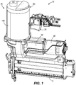
FIG. 1 is a perspective view of a powered fastener driver in accordance with an embodiment of the invention. -
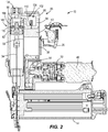
FIG. 2 is a cross-sectional view of the powered fastener driver ofFIG. 1 . -
FIG. 3 is an enlarged, partial cross-sectional view of the powered fastener driver ofFIG. 2 . -
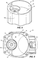
FIG. 4 is a perspective view of the powered fastener driver ofFIG. 1 , with a head assembly removed to illustrate a compressor piston and a drive piston. -
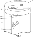
FIG. 5 is a top view of the of the powered fastener driver ofFIG. 1 , illustrating the compressor piston and the drive piston. -
FIG. 6 is a partial perspective view of the powered fastener driver ofFIG. 1 , illustrating a valve in fluid communication with a drive cylinder and a compressor cylinder. -
FIG. 7A is a cross-sectional view of a mechanical pressure valve of the powered fastener driver ofFIG. 1 , illustrating the mechanical pressure valve in a closed position. -
FIG. 7B is a cross-sectional view of the mechanical pressure valve ofFIG. 7A , illustrating the mechanical pressure valve in an open position. -
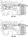
FIG. 8A is a schematic view of the powered fastener driver ofFIG. 1 , illustrating the start of an operation cycle. -
FIG. 8B is a schematic view of the powered fastener driver ofFIG. 8A , illustrating a first compression stroke of a compressor piston. -
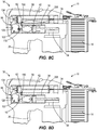
FIG. 8C is a schematic view of the powered fastener driver ofFIG. 8A , illustrating a first retraction stroke of the compressor piston. -
FIG. 8D is a schematic view of the powered fastener driver ofFIG. 8A , illustrating a second compression stroke of the compressor piston. -
FIG. 8E is a schematic view of the powered fastener driver ofFIG. 8A , illustrating the completion of the second compression stroke of the compressor piston. -
FIG. 8F is a schematic view of the powered fastener driver ofFIG. 8A , illustrating a sensor detecting a threshold pressure level present in a storage chamber. -
FIG. 8G is a schematic view of the powered fastener driver ofFIG. 8A , illustrating a pressure valve in an open position. -
FIG. 8H is a schematic view of the powered fastener driver ofFIG. 8A , illustrating a drive stroke of a drive piston. -
FIG. 8I is a schematic view of the powered fastener driver ofFIG. 8A , illustrating the completion of the drive stroke of the drive piston and the pressure valve in an open position. -
FIG. 8J is a schematic view of the powered fastener driver ofFIG. 8A , illustrating the completion of the drive stroke of the drive piston and the pressure valve in a closed position. -
FIG. 8K is a schematic view of the powered fastener driver ofFIG. 8A , illustrating a second retraction stroke of the compressor piston and a return stroke of the drive piston. -
FIG. 8L is a schematic view of the powered fastener driver ofFIG. 8A , illustrating a completion of the operation cycle. - Before any embodiments of the invention are explained in detail, it is to be understood that the present invention is not limited in its application to the details of construction and the arrangement of components set forth in the following description or illustrated in the following drawings. The present invention is capable of other embodiments and of being practiced or of being carried out in various ways.
- With reference to
FIG. 1 , apowered fastener driver 10 is operable to drive fasteners (e.g., nails, tacks, staples, etc.) held within amagazine 14 into a workpiece. Thepowered fastener driver 10 includes an outer housing with a handle portion, and a user-actuatedtrigger 26 mounted on the handle portion. Notably, thepowered fastener driver 10 does not require an external source of air pressure, but rather the poweredfastener driver 10 includes an on-board air compressor 30. In this way, the weight and/or size of tool may be reduced. The on-board air compressor 30 is powered by a power source (e.g., a battery pack), coupled to a battery attachment portion of the outer housing. - With reference to
FIGS. 1 and2 , thepowered fastener driver 10 includes adrive blade 34 actuated by the on-board air compressor 30 to drive the fasteners into a workpiece. Thecompressor 30 includes acompressor cylinder 38 and acompressor piston 42 in thecompressor cylinder 38 driven in a reciprocating manner by a reciprocating mechanism including amotor 46, atransmission 50, and acrank arm assembly 54. Thepowered fastener driver 10 also includes adrive cylinder 58 and adrive piston 62 slidably disposed in thedrive cylinder 58. Thedrive piston 62 is movable between a top-dead-center position (FIG. 8A ) and a bottom-dead-center position (FIG. 8H ). Similarly, thecompressor piston 42 is moveable between a top-dead-center position (FIG. 8B ) and a bottom-dead-center position (FIG. 8A ). - As shown in
FIGS. 2 and4 , thesmaller drive cylinder 58 at least partially extends into thelarger compressor cylinder 38. However, thecompressor piston 42 does not surround theentire drive cylinder 58. Instead, thecompressor piston 42 is kidney-shaped (i.e., bean-shaped) and only partially wraps around thedrive cylinder 58. Thecompressor piston 42, therefore, has a different shape than thedrive piston 62. In other words, thecompressor piston 42 is not circular, but rather is non-circularly shaped. In particular, thecompressor piston 42 includes an outerconvex surface 66, an innerconcave surface 70, and rounded ends 74 connecting theouter surface 66 with the inner surface 70 (FIG. 5 ). In this way, the size and/or weight of thefastener driver 10 may be advantageously reduced for improved handling, manufacturability, and/or the like. For example, thecompressor piston 42 defines asurface area 78, and if an equivalent surface area was reconfigured as a traditional circular piston, illustrated as a dashedcircle 82 inFIG. 5 , the size of the tool would be increased. By partially nesting and/or wrapping thecompressor piston 42 around thedrive cylinder 58, the overall size of the on-board compressor 30, and thus thefastener driver 10, is reduced. In some embodiments, the volume compressed by a single stroke of thecompressor piston 42 is approximately 0.000107 cubic meters (6.5 cubic inches) and achieves a compression ratio of approximately 5.3:1 per stroke. - With reference to
FIG. 3 , the on-board air compressor 30 includes ahead assembly 86 positioned at a top end of thecylinders head assembly 86 includes anend cap 90, afirst portion 94 of which is positioned within thecompressor cylinder 38 and asecond portion 98 of which is positioned within thedrive cylinder 58. Apressure storage chamber 102 is formed within thehead assembly 86. As explained in greater detail below, thepressure storage chamber 102 is capable of fluidly communicating with thecompressor cylinder 38 and thedrive cylinder 58. Thefirst portion 94 of thehead assembly 86 includes afirst passageway 106 that fluidly communicates thecompressor cylinder 38 and thepressure storage chamber 102. - A
first check valve 110 is positioned within thefirst passageway 106 between thecompressor cylinder 38 and thepressure storage chamber 102. Thefirst check valve 110 is a one-way valve that permits air to flow into thepressure storage chamber 102 from thecompressor cylinder 38, but does not permit air to flow into thecompressor cylinder 38 from thepressure storage chamber 102. In the illustrated embodiment, thefirst check valve 110 includes aball 114 that is biased by acompression spring 118 into aseat 122 around thefirst passageway 106. As explained in greater detail below, compressed air created by thecompressor piston 42 unseats theball 114 from theseat 122 and flows into thepressure storage chamber 102. During other times, thespring 118 biases theball 114 into theseat 122 to seal thepressure storage chamber 102 from thecompressor cylinder 38. - A
pressure sensor 126 is partially positioned within thepressure storage chamber 102 and is configured to detect a pressure level within thepressure storage chamber 102. Thepressure sensor 126 is electrically coupled to a control system (i.e., a controller). In some embodiments, the pressure detected within thepressure storage chamber 102 by thepressure sensor 126 is utilized by the controller to determine when to de-energize themotor 46. In other embodiments, the pressure detected within thepressure storage chamber 102 by thepressure sensor 126 is utilized by the controller to determine when to energize a solenoid-actuated pressure valve that communicates thepressure storage chamber 102 with thedrive cylinder 58. In the illustrated embodiment, thehead assembly 86 includes apassageway 130 in which to receive a portion of thepressure sensor 126. Thepassageway 130 extends between thepressure storage chamber 102 and the exterior of thehead assembly 86. - A pressure valve 134 (i.e., a pressure release valve, a firing valve, and/or the like) is positioned within the
head assembly 86 and selectively fluidly communicates thepressure storage chamber 102 with thedrive cylinder 58. Thepressure valve 134 may be an electrically actuated valve or a pressure-actuated valve (i.e., a valve that is responsive to external forces applied by the compressed air in the pressure storage chamber 102). Thepressure valve 134 remains in a closed position (FIG. 7A ) as the pressure within thepressure storage chamber 102 increases. Upon reaching a threshold pressure value within thepressure storage chamber 102, thepressure valve 134 moves to an open position (FIG. 7B ). When thepressure valve 134 is in the open position, the pressure within thepressure storage chamber 102 is fluidly communicated to thedrive cylinder 58. As described in further detail below, when thepressure valve 134 opens, the pressure within thepressure storage chamber 102 moves thedrive piston 62 toward a bottom-dead-center position causing a fastener to be driven into a workpiece by thedrive blade 34. - With references to
FIGS. 7A and 7B , thepressure valve 134 is illustrated as a pressure-actuated release valve. Thepressure valve 134 includes aplunger 138 with afirst surface 142 and asecond surface 146. Thefirst surface 142 is opposite of (i.e., in facing relationship to) thesecond surface 146. In the illustrated embodiment, thefirst surface 142 is larger than thesecond surface 146. Thefirst surface 142 and thesecond surface 146 are in fluid communication with thepressure storage chamber 102. In some embodiments, thefirst surface 142 and thesecond surface 146 partially define thepressure storage chamber 102. Aspring 150 biases theplunger 138 into a first position (FIG. 7A ) in which thepressure storage chamber 102 is sealed from thedrive cylinder 58 by a sealingplate 162. - When the pressure within the
pressure storage chamber 102 reaches a threshold pressure value (i.e., a firing pressure), theplunger 138 is caused to automatically move to a second position (FIG. 7B ) in which thepressure storage chamber 102 is fluidly communicated with thedrive cylinder 58. More specifically, when the pressure in thepressure storage chamber 102 is at or below the threshold, aforce 154 acting upward (as viewed inFIG. 7A ) on thefirst surface 142 and aforce 158 acting downward (as viewed inFIG. 7A ) on thesecond surface 146 are approximately the same and essentially cancel each other out. As a result of the approximatelyequal forces spring 150 keeps theplunger 138 in the closed position. Once the pressure within thepressure storage chamber 102 reaches the threshold pressure value, theforce 154 acting on thefirst surface 142 is much larger than theforce 158 acting on thesecond surface 146. In other words, thefirst surface 142 is larger than thesecond surface 146 so the force acting on thefirst surface 142 is larger when bothsurfaces first surface 142 and the force acting on thesecond surface 146 causes theplunger 138 to move (e.g., slide, translate, and/or the like) against the bias of thespring 150 into the open position (FIG. 7B ). As theplunger 138 is lifted from the seated, closed position, the pressure from thepressure storage chamber 102 surrounds the sealingplate 162 of theplunger 138 so that the pressure is no longer creating a net force acting on thesecond surface 146. As such, theplunger 138 will quickly move to the open position once thebottom sealing plate 162 of theplunger 138 has been unseated. Theplunger 138 may remain in the open position until the pressure drops and thespring 150 biases theplunger 138 back into the seated, closed position. - In some embodiments, the threshold pressure value at which the
pressure valve 134 moves from the closed position (FIG. 7A ) to the open position (FIG. 7B ) can be adjusted or controlled by the design of the difference in surface area of thefirst surface 142 and thesecond surface 146, and with the stiffness of thespring 150. In this way, the amount of pressure acting on thedrive piston 62 may be increased or decreased for driving different sizes of fasteners (e.g., 16 gauge nails, 18 gauge nails, and/or the like) to appropriate distances within a workpiece. In this way, thefastener driver 10 may be suitable for use in a variety of different fastening applications. For example, with a given spring a plunger with a first surface that is two times the size of the second surface will move to an open position at a lower threshold pressure value than a plunger with a surface 1.5 times the size of the second surface. Likewise, with a given plunger, a stiffer spring will cause the plunger to move open at a higher threshold pressure value. - In other embodiments, the pressure valve is an electronically controlled solenoid valve that is actuated between an open position (fluidly communicating the
drive cylinder 58 with the pressure storage chamber 102) and a closed position (sealing thedrive cylinder 58 from the pressure storage chamber 102). In some embodiments, thefirst surface 142 of the plunger is equal to thesecond surface 146, and the plunger is actuated by the electrical actuator. The output from thepressure sensor 126 is utilized by the controller to determine when to actuate the solenoid and open the pressure valve. - With reference to
FIG. 3 , thedrive piston 62 includes abody 166 and aferromagnetic cap 170 is secured to thebody 166 by a threadedfastener 174. Thedrive blade 34 may be attached to themain body 166 of thedrive piston 62 by apin 178 interference-fit to themain body 166. Amagnetic latch 182 may be capable of holding thedrive piston 62 in the top-dead-center position by way of a magnetic force. Thelatch 182 may include anannular magnet 186 positioned near the top of thedrive cylinder 58. Theannular magnet 186 may emit a magnetic field that magnetically attracts theferromagnetic cap 170, which is also a part of themagnetic latch 182. Alternatively, themagnetic latch 182 could include a ferromagnetic portion positioned near the top of thedrive cylinder 58 and a magnet secured to thedrive piston 62. - With reference to
FIG. 6 , asecond check valve 190 may be positioned within acutout 194 formed between asidewall 198 of thecompressor cylinder 38 and asidewall 202 of thedrive cylinder 58. Thesecond check valve 190 may be a one-way valve the permits air to flow into thecompressor cylinder 38 from thedrive cylinder 58, but does not permit air to flow into thedrive cylinder 58 from thecompressor cylinder 38. In the illustrated embodiment, thesecond check valve 190 is a spring-biased ball valve like thefirst check valve 110 described above. As explained in greater detail below, air is drawn into thecompressor cylinder 38 through thesecond check valve 190 as thecompressor piston 42 retracts towards the bottom-dead-center position. Holes 206 (i.e., vents, apertures, openings, and/or the like;FIGS. 8A-8L ) are formed in the bottom of thedrive cylinder 58 and permit atmosphere to enter thedrive cylinder 58. - With reference to
FIGS. 8A-8L , a fastener driving operation (i.e., a drive cycle, an operation cycle, and/or the like) of thepowered fastener driver 10 is illustrated. With reference toFIG. 8A , at the beginning of the operation cycle, themagnetic latch 182 maintains thedrive piston 62 in the top-dead-center position, while thecompressor piston 42 is in the bottom-dead-center position. When the user of thedriver 10 depresses the trigger 26 (FIG. 8A ), thecompressor piston 42 is driven upward and toward the top end of thecompressor cylinder 38 by themotor 46 and crank arm assembly 54 (FIG. 8B ). As thecompressor piston 42 travels upward, the air in thecompressor cylinder 38 and above thecompressor piston 42 is compressed. The compressed air in thecompressor cylinder 38 passes through thefirst check valve 110 and enters thepressure storage chamber 102. After thecompressor piston 42 completes a first compression stroke, the pressure within thepressure storage chamber 102 may remain below the threshold pressure value for initiating a firing operation, and therefore, thedrive piston 62 remains in the top-dead-center position. In other words, more than one compression stroke (i.e., multiple compression strokes) is required to achieve the threshold pressure value within thepressure storage chamber 102. - With reference to
FIG. 8C , thecompressor piston 42 is driven through a first retraction stroke. Atmospheric air from theholes 206 is drawn into thecompressor cylinder 38 through thesecond check valve 190. With reference toFIG. 8D , thecompressor piston 42 is driven through a second compression stroke, again compressing the air within thecompressor cylinder 38. With reference toFIG. 8E , the compressed air within thecompressor cylinder 38 moves through thefirst check valve 110 and continues to build the pressure within thepressure storage chamber 102. - With reference to
FIG. 8F , thepressure sensor 126 detects the pressure within thepressure storage chamber 102 satisfied (e.g., reached, and/or the like) the threshold pressure value, which may be achieved after two or more compression strokes of thecompressor piston 42. With reference toFIG. 8G , upon reaching or satisfying the pressure threshold value, thepressure valve 134 is moved to an open position. As discussed above, thepressure valve 134 in the illustrated embodiment is a pressure-actuated valve that opens automatically in response to the threshold pressure value being reached. Alternatively, thepressure valve 134 may be electronically controlled to be actuated to the open position in response to the pressure detected by thepressure sensor 126. - With reference to
FIG. 8H , with thepressure valve 134 in the open position, the compressed air within thepressure storage chamber 102 rushes into thedrive cylinder 58. The force of the compressed air acting on thedrive piston 62 overcomes the magnetic force of themagnetic latch 182 acting on thedrive piston 62, and thedrive piston 62 is accelerated downward within thedrive cylinder 58 by the compressed air. As thedrive piston 62 is driven downwards, thedrive blade 34 impacts a fastener held in themagazine 14 and drives the fastener into a workpiece until thedrive piston 62 reaches the bottom-dead-center position (FIG. 8I ). Once thedrive piston 62 reaches bottom-dead-center, thepressure valve 134 is moved back into the closed position (FIG. 8J ). - With reference to
FIG. 8K , to prepare for a subsequent fastener driving operation, thecompressor piston 42 is driven downwards towards the bottom-dead-center position by themotor 46 and crankarm assembly 54. As thecompressor piston 42 is driven through a retraction stroke, a vacuum is created within thecompressor cylinder 38 and thedrive cylinder 58. Specifically, thesecond check valve 190 allows the vacuum to be communicated to thedrive cylinder 58 above thedrive piston 62. The vacuum draws thedrive piston 62 upwards in thedrive cylinder 58 until theferromagnetic cap 170 of thedrive piston 62 reaches top-dead-center, after which time themagnetic latch 182 again holds or maintains thedrive piston 62 in the top-dead-center position. With thedrive piston 62 retained in the top-dead-center position, retraction of thecompressor piston 42 continues to draw in atmospheric air from theholes 206 flowing through the second check valve 190 (FIG. 8L ). At which point, the operation cycle has been completed and thefastener driver 10 is ready for the next operation cycle in response to user actuation of thetrigger 26, for example (FIG. 8A ). - Although the present invention has been described in detail with reference to certain preferred embodiments, variations and modifications exist within the scope of one or more independent aspects of the present invention as described.
- Various features of the invention are set forth in the claims.
Claims (15)
- A powered fastener driver comprising:a cylinder; anda piston positioned within the cylinder, the piston being moveable between a top-dead-center position and a bottom-dead-center position, the piston having a non-circular shape.
- The powered fastener driver of claim 1,
wherein the piston has a kidney-bean shape; and/or
wherein the piston is a compressor piston that is driven between the top-dead-center position and the bottom-dead-center position by a reciprocating mechanism. - The powered fastener driver of claim 1 or 2, wherein:the cylinder is a first cylinder,the piston is a first piston, andthe powered fastener driver further comprises:a second cylinder in selective fluid communication with the first cylinder,a second piston positioned within the second cylinder, the second piston being moveable between a top-dead-center position and a bottom-dead-center position, anda drive blade coupled to the second piston for movement therewith.
- The powered fastener driver of claim 3,
wherein the second piston has a different shape than the first piston; and/or
wherein the first piston only partially wraps around the second piston. - The powered fastener driver of claim 3 or 4, further comprising a reciprocating mechanism configured to drive the first piston between the top-dead-center position and the bottom-dead-center position, wherein the second piston is driven from the top-dead-center position to the bottom-dead-center position in response to the movement of the first piston.
- The powered fastener driver of any one of claims 3 to 5, further comprising:a pressure storage chamber in selective fluid communication with the first cylinder, anda pressure valve positioned between the pressure storage chamber and the second cylinder, wherein the pressure valve is configured to move from a closed position to an open position in response to the pressure within the pressure storage chamber reaching a threshold pressure.
- A powered fastener driver comprising:a first cylinder;a first piston positioned within the first cylinder, the first piston being moveable between a top-dead-center position and a bottom-dead-center position;a pressure storage chamber in fluid communication with the first cylinder;a second cylinder in selective fluid communication with the pressure storage chamber;a second piston positioned within the second cylinder, the second piston being moveable between a top-dead-center position and a bottom-dead-center position to initiate a fastener driving operation;a drive blade coupled to the second piston for movement therewith; anda pressure valve positioned between the pressure storage chamber and the second cylinder, wherein the pressure valve is configured to move from a closed position to an open position in response to the pressure within the pressure storage chamber reaching a threshold pressure.
- The powered fastener driver of claim 7, further comprising a reciprocating mechanism configured to drive the first piston between the top-dead-center position and the bottom-dead-center position, wherein the second piston is driven from the top-dead-center position to the bottom-dead-center position in response to the movement of the first piston.
- The powered fastener driver of claim 7 or 8, further comprising a pressure sensor positioned within the pressure storage chamber, wherein the pressure sensor is electronically coupled to a control system of the powered fastener driver.
- The powered fastener driver of claim 9, wherein
the pressure valve is a solenoid-actuated valve, and
the pressure detected within the pressure storage chamber by the pressure sensor is utilized by the control system to determine when to energize the solenoid-actuated valve. - The powered fastener driver of any one of claims 7 to 10, further comprising a first check valve positioned between the first cylinder and the pressure storage chamber, wherein the first check valve is configured to open to permit air flow into the pressure storage chamber from the first cylinder, and optionally: further comprising a second check valve positioned between the first cylinder and the second cylinder, wherein the second check valve is configured to open to permit air to flow into the first cylinder from the second cylinder.
- The powered fastener driver of any one of claims 7 to 11,
wherein the second piston includes a magnetic latch that interacts with an annular magnet positioned near the second cylinder to hold the second piston in the top-dead-center position. - A powered fastener driver comprising:a first cylinder;a first piston positioned within the first cylinder, the first piston being moveable between a top-dead-center position and a bottom-dead-center position;a second cylinder in selective fluid communication with the first cylinder;a second piston positioned within the second cylinder, the second piston being moveable between a top-dead-center position and a bottom-dead-center position to initiate a fastener driving operation;a drive blade coupled to the second piston for movement therewith; anda check valve positioned between the second cylinder and the first cylinder, wherein the check valve is configured to open to permit air to flow into the first cylinder from the second cylinder.
- The powered fastener driver of claim 13, further comprising:(i) a pressure storage chamber in selective fluid communication with the first cylinder, a first check valve positioned between the first cylinder and the pressure storage chamber, wherein the first check valve is configured to open to permit air flow into the pressure storage chamber from the first cylinder, and wherein the check valve is a second valve; and/or(ii) a reciprocating mechanism configured to drive the first piston between the top-dead-center position and the bottom-dead-center position, wherein the second piston is driven from the top-dead-center position to the bottom-dead-center position in response to the movement of the first piston.
- The powered fastener driver of any one of claims 7 to 14, wherein the first piston has a non-circular shape.
Applications Claiming Priority (1)
| Application Number | Priority Date | Filing Date | Title |
|---|---|---|---|
| US202063048868P | 2020-07-07 | 2020-07-07 |
Publications (1)
| Publication Number | Publication Date |
|---|---|
| EP3936282A1 true EP3936282A1 (en) | 2022-01-12 |
Family
ID=76829380
Family Applications (1)
| Application Number | Title | Priority Date | Filing Date |
|---|---|---|---|
| EP21184108.5A Pending EP3936282A1 (en) | 2020-07-07 | 2021-07-06 | Powered fastener driver |
Country Status (4)
| Country | Link |
|---|---|
| US (1) | US11819989B2 (en) |
| EP (1) | EP3936282A1 (en) |
| CN (1) | CN216372032U (en) |
| CA (1) | CA3123878A1 (en) |
Families Citing this family (7)
| Publication number | Priority date | Publication date | Assignee | Title |
|---|---|---|---|---|
| CA3167425A1 (en) | 2021-07-16 | 2023-01-16 | Techtronic Cordless Gp | Powered fastener driver |
| JP7739134B2 (en) * | 2021-10-26 | 2025-09-16 | 株式会社マキタ | Driving tools |
| EP4543633A1 (en) * | 2022-06-22 | 2025-04-30 | Black & Decker Inc. | Fastening tool having position biased release valve |
| DE102023212240A1 (en) * | 2023-12-05 | 2025-06-05 | Robert Bosch Gesellschaft mit beschränkter Haftung | Driving tool with a gas spring mechanism |
| CN120962587A (en) * | 2024-05-08 | 2025-11-18 | 南京泉峰科技有限公司 | Fastener driver |
| US20260027686A1 (en) * | 2024-06-06 | 2026-01-29 | Illinois Tool Works Inc. | Fastener-driving tool with chamber member retaining assembly |
| EP4686530A1 (en) * | 2024-07-31 | 2026-02-04 | Hilti Aktiengesellschaft | A device and a method for driving a fastener into a workpiece |
Citations (4)
| Publication number | Priority date | Publication date | Assignee | Title |
|---|---|---|---|---|
| US3035268A (en) * | 1959-10-05 | 1962-05-22 | Modernair Corp | Pneumatically-operated fastener driving machine |
| WO2011010634A1 (en) * | 2009-07-24 | 2011-01-27 | 株式会社マキタ | Hammering tool |
| US8079504B1 (en) * | 2010-11-04 | 2011-12-20 | Tricord Solutions, Inc. | Fastener driving apparatus |
| US9050712B2 (en) * | 2011-01-20 | 2015-06-09 | Black & Decker Inc. | Driving tool with internal air compressor |
Family Cites Families (126)
| Publication number | Priority date | Publication date | Assignee | Title |
|---|---|---|---|---|
| US942163A (en) | 1909-12-07 | August Berner | Pneumatic power-hammer. | |
| US317212A (en) | 1885-05-05 | Max eubin | ||
| US1072358A (en) | 1905-11-25 | 1913-09-02 | Pneumelectric Machine Company | Fluid-pressure-driven tool. |
| US1072367A (en) | 1912-05-08 | 1913-09-02 | Pneumelectric Machine Company | Double-compression reciprocating implement. |
| US1829609A (en) | 1929-05-06 | 1931-10-27 | Frank R Robinson | Pneumatic hammer |
| US3150488A (en) | 1961-11-22 | 1964-09-29 | Emmett L Haley | Power devices |
| DE1277166B (en) | 1963-04-27 | 1968-09-05 | Behrens Friedrich Joh | Device operated with compressed air for driving in nails, staples or the like. |
| GB1044288A (en) | 1964-09-17 | 1966-09-28 | Gen Wire Overseas Corp | Power devices suitable for operating hand tools |
| FR1414089A (en) | 1964-09-21 | 1965-10-15 | Gen Wire Overseas Corp | Motor device for hand tool |
| US3567098A (en) | 1966-12-23 | 1971-03-02 | Bostitch Div Of Textron | Fastener driving apparatus operable under pressure conditions greater than line pressure |
| GB1243472A (en) * | 1969-03-15 | 1971-08-18 | Daiichi Kikai Seisakusho Co Lt | A free-piston type percussion device with an air pump |
| SE343784B (en) | 1969-11-07 | 1972-03-20 | Atlas Copco Ab | |
| SE371128B (en) | 1971-08-02 | 1974-11-11 | K Charlez | |
| JPS519199B2 (en) | 1972-04-03 | 1976-03-24 | ||
| US4192389A (en) | 1978-08-02 | 1980-03-11 | Boeing Commercial Airplane Company | Single impact rivet gun |
| DE2946387C2 (en) | 1979-11-16 | 1986-04-10 | Signode Corp., Glenview, Ill. | Pneumatically actuated driving tool |
| US4415110A (en) | 1981-08-17 | 1983-11-15 | Hunter C Lamont | LP Gas-operated impact tool |
| JPH0747270B2 (en) | 1986-09-13 | 1995-05-24 | 松下電工株式会社 | Battery powered nailer |
| DE3728454C2 (en) | 1987-08-26 | 1993-12-23 | Bosch Gmbh Robert | Pressurized impact device |
| DE3826213A1 (en) | 1988-08-02 | 1990-02-15 | Bosch Gmbh Robert | DRILLING HAMMER |
| US4913331A (en) | 1988-10-21 | 1990-04-03 | Hitachi Koki Company, Ltd. | Internal-combustion piston driving apparatus having a decompression channel |
| JP3676879B2 (en) | 1995-07-25 | 2005-07-27 | 株式会社マキタ | Fastener driving tool |
| US6158643A (en) | 1997-12-31 | 2000-12-12 | Porter-Cable Corporation | Internal combustion fastener driving tool piston and piston ring |
| US6231319B1 (en) * | 1998-02-13 | 2001-05-15 | Matsushita Electric Industrial Co., Ltd. | Hermetic compressor |
| US6672498B2 (en) | 1999-09-17 | 2004-01-06 | Stanley Fastening Sytems Lp | Feed system for nailer |
| DE10033362A1 (en) | 2000-07-08 | 2002-01-17 | Hilti Ag | Electric hand tool with empty stroke shutdown |
| US6796475B2 (en) | 2000-12-22 | 2004-09-28 | Senco Products, Inc. | Speed controller for flywheel operated hand tool |
| ES2208623T3 (en) | 2001-03-07 | 2004-06-16 | Black & Decker Inc. | HAMMER. |
| US7225959B2 (en) | 2001-04-30 | 2007-06-05 | Black & Decker, Inc. | Portable, battery-powered air compressor for a pneumatic tool system |
| US7494035B2 (en) | 2001-04-30 | 2009-02-24 | Black & Decker Inc. | Pneumatic compressor |
| TW570864B (en) | 2001-05-17 | 2004-01-11 | Li-Jeng Jang | Portable pneumatic tool |
| US6705503B1 (en) | 2001-08-20 | 2004-03-16 | Tricord Solutions, Inc. | Electrical motor driven nail gun |
| US6604666B1 (en) | 2001-08-20 | 2003-08-12 | Tricord Solutions, Inc. | Portable electrical motor driven nail gun |
| US7032683B2 (en) | 2001-09-17 | 2006-04-25 | Milwaukee Electric Tool Corporation | Rotary hammer |
| US6874452B2 (en) * | 2002-01-15 | 2005-04-05 | Joseph S. Adams | Resonant combustion chamber and recycler for linear motors |
| US20040232194A1 (en) | 2002-03-07 | 2004-11-25 | Pedicini Christopher S. | Enhanced electrical motor driven nail gun |
| DE10260704A1 (en) | 2002-12-23 | 2004-07-01 | Hilti Ag | Combustion-powered setting tool |
| CN1798954A (en) | 2003-06-12 | 2006-07-05 | 三索解决方案公司 | Portable electric driven compressed air gun |
| US20080217372A1 (en) | 2003-12-30 | 2008-09-11 | Poly Systems Pty Ltd | Fastener Driving Tool |
| EP1773545A2 (en) | 2004-07-23 | 2007-04-18 | Gavin Beales | Nailer device |
| US6971567B1 (en) | 2004-10-29 | 2005-12-06 | Black & Decker Inc. | Electronic control of a cordless fastening tool |
| US20060180631A1 (en) | 2005-02-16 | 2006-08-17 | Chris Pedicini | Electric motor driven energy storage device for impacting |
| DE102005000061A1 (en) | 2005-05-18 | 2006-11-23 | Hilti Ag | Electrically operated tacker |
| JP2008544864A (en) | 2005-06-29 | 2008-12-11 | ポリ・システムズ・プロプライエタリー・リミテッド | Portable power tools |
| DE102005000107B4 (en) | 2005-08-25 | 2014-03-13 | Hilti Aktiengesellschaft | Pneumatically operated setting tool |
| US7419079B2 (en) | 2006-02-03 | 2008-09-02 | Basso Industry Corp. | Pneumatic tool |
| JP2007222989A (en) | 2006-02-23 | 2007-09-06 | Max Co Ltd | Drive piston holding structure in gas nailer |
| US20080078799A1 (en) | 2006-10-03 | 2008-04-03 | Wan-Fu Wen | Nail Gun with Electric Power Generating Unit |
| US8875969B2 (en) | 2007-02-09 | 2014-11-04 | Tricord Solutions, Inc. | Fastener driving apparatus |
| JP2008255813A (en) | 2007-04-02 | 2008-10-23 | Max Co Ltd | Gas internal combustion type nail driver |
| US8276798B2 (en) | 2007-06-21 | 2012-10-02 | Illinois Tool Works Inc. | Feeder mechanism retention device for fastener driving tool |
| US7984708B2 (en) | 2007-08-27 | 2011-07-26 | Impulse Solutions, Llc | Projectile launching apparatus |
| US8011547B2 (en) | 2007-10-05 | 2011-09-06 | Senco Brands, Inc. | Fastener driving tool using a gas spring |
| JP5146734B2 (en) | 2008-01-15 | 2013-02-20 | 日立工機株式会社 | Fastener driving machine |
| DE102008000909A1 (en) | 2008-04-01 | 2009-10-08 | Hilti Aktiengesellschaft | Internal combustion setting device |
| US8550321B2 (en) | 2008-05-21 | 2013-10-08 | Poly Systems Pty Ltd | Tool for driving fasteners |
| JP5212713B2 (en) | 2008-09-05 | 2013-06-19 | 日立工機株式会社 | air compressor |
| US20100072248A1 (en) | 2008-09-19 | 2010-03-25 | Basso Industry Corp. | Nailing force-adjusting device for a pneumatic nail gun |
| EP2367662A1 (en) * | 2008-12-24 | 2011-09-28 | Globalforce Ip Limited | Vaporisation system |
| US7793811B1 (en) | 2009-02-25 | 2010-09-14 | Tricord Solutions, Inc. | Fastener driving apparatus |
| JPWO2011010511A1 (en) | 2009-07-24 | 2012-12-27 | トリコード ソリューションズ,インコーポレイティド | Driving tool |
| JP2012187640A (en) | 2009-07-24 | 2012-10-04 | Makita Corp | Hammering tool |
| DE102009041824A1 (en) | 2009-09-18 | 2011-03-24 | Hilti Aktiengesellschaft | Device for transmitting energy to a fastener |
| US8523035B2 (en) | 2009-11-11 | 2013-09-03 | Tricord Solutions, Inc. | Fastener driving apparatus |
| US20110180581A1 (en) | 2010-01-24 | 2011-07-28 | De Poan Pneumatic Corp. | Resetting and Driving Mechanism for Nail Driving Rod in Pneumatic Nailer having Embedded Air Compressor |
| US20120085226A1 (en) * | 2010-10-08 | 2012-04-12 | Bradhart Products, Inc. | Gas Piston System Actuator Assembly for Rifle Automatic Ejection and Reload |
| MX344420B (en) | 2010-11-04 | 2016-12-15 | John Witzigreuter | Fastener driving apparatus. |
| JP5551050B2 (en) | 2010-11-24 | 2014-07-16 | 株式会社マキタ | Air compressor |
| US8800834B2 (en) | 2011-05-11 | 2014-08-12 | Tricord Solutions, Inc. | Fastener driving apparatus |
| US9770818B2 (en) * | 2011-10-03 | 2017-09-26 | Illinois Tool Works Inc. | Fastener driving tool with portable pressurized power source |
| AU2012323764A1 (en) | 2011-10-13 | 2014-07-03 | Poly Systems Pty Ltd | Hand held power tool for driving fasteners |
| JP5800749B2 (en) | 2012-04-09 | 2015-10-28 | 株式会社マキタ | Driving tool |
| JP5800748B2 (en) | 2012-04-09 | 2015-10-28 | 株式会社マキタ | Driving tool |
| JP5859372B2 (en) | 2012-04-27 | 2016-02-10 | 株式会社マキタ | Driving tool |
| JP2013233609A (en) | 2012-05-08 | 2013-11-21 | Makita Corp | Driving tool |
| JP5758841B2 (en) | 2012-05-08 | 2015-08-05 | 株式会社マキタ | Driving tool |
| DE102012210347A1 (en) | 2012-06-19 | 2013-12-19 | Hilti Aktiengesellschaft | Setting tool and control method |
| US8733610B2 (en) | 2012-08-21 | 2014-05-27 | Tricord Solutions, Inc. | Fastener driving apparatus |
| JP2014083601A (en) | 2012-10-19 | 2014-05-12 | Makita Corp | Driving tool |
| JP2014091196A (en) | 2012-11-05 | 2014-05-19 | Makita Corp | Driving tool |
| JP5921037B2 (en) | 2012-11-12 | 2016-05-24 | 株式会社マキタ | Driving tool |
| JP2014104533A (en) | 2012-11-27 | 2014-06-09 | Makita Corp | Driving tool |
| JP2014104534A (en) | 2012-11-27 | 2014-06-09 | Makita Corp | Driving tool |
| JP2014108495A (en) | 2012-12-03 | 2014-06-12 | Makita Corp | Driving tool |
| US9555530B2 (en) | 2013-06-20 | 2017-01-31 | Tricord Solutions, Inc. | Fastener driving apparatus |
| US8939341B2 (en) | 2013-06-20 | 2015-01-27 | Tricord Solutions, Inc. | Fastener driving apparatus |
| EP2826599A1 (en) | 2013-07-16 | 2015-01-21 | HILTI Aktiengesellschaft | Control method and hand tool machine |
| EP2826601A1 (en) | 2013-07-16 | 2015-01-21 | HILTI Aktiengesellschaft | Control method and hand tool machine |
| EP2826600A1 (en) | 2013-07-16 | 2015-01-21 | HILTI Aktiengesellschaft | Control method and hand tool machine |
| US9662777B2 (en) | 2013-08-22 | 2017-05-30 | Techtronic Power Tools Technology Limited | Pneumatic fastener driver |
| EP2851157A1 (en) | 2013-09-19 | 2015-03-25 | HILTI Aktiengesellschaft | Driving device with pneumatic storage |
| EP2851158A1 (en) | 2013-09-19 | 2015-03-25 | HILTI Aktiengesellschaft | Driving device with heated pneumatic reservoir |
| JP6100680B2 (en) | 2013-12-11 | 2017-03-22 | 株式会社マキタ | Driving tool |
| CA2943806C (en) | 2014-03-27 | 2022-05-31 | Techtronic Power Tools Technology Limited | Powered fastener driver and operating method thereof |
| JP6284417B2 (en) | 2014-04-16 | 2018-02-28 | 株式会社マキタ | Driving tool |
| GB2556457B (en) * | 2015-04-30 | 2021-10-13 | Koki Holdings Co Ltd | Fastener driving machine |
| CN204736190U (en) | 2015-06-26 | 2015-11-04 | 张华定 | Nailer |
| WO2017015654A1 (en) | 2015-07-23 | 2017-01-26 | Tricord Solutions, Inc. | Fastener driving apparatus |
| US20180243891A1 (en) | 2015-09-14 | 2018-08-30 | Hilti Aktiengesellschaft | Fuel gas-fired driving-in tool with charging function |
| EP3141348A1 (en) | 2015-09-14 | 2017-03-15 | HILTI Aktiengesellschaft | Driving device powered by combustion gas with valve member |
| EP3181295A1 (en) | 2015-12-18 | 2017-06-21 | HILTI Aktiengesellschaft | Internal combustion operated driving tool |
| EP3184250A1 (en) | 2015-12-22 | 2017-06-28 | HILTI Aktiengesellschaft | Internal combustion gas operated driving tool |
| CN105818099B (en) | 2016-05-26 | 2017-11-17 | 杭州科龙电器工具股份有限公司 | Use the electric nail gun of gas spring |
| US20170361443A1 (en) | 2016-06-20 | 2017-12-21 | Black & Decker Inc. | Cylindrical Integrated Valve Assembly |
| US20180207777A1 (en) | 2016-07-06 | 2018-07-26 | Tti (Macao Commercial Offshore) Limited | Powered fastener driver |
| US20180009097A1 (en) | 2016-07-06 | 2018-01-11 | Tti (Macao Commercial Offshore) Limited | Powered fastener driver |
| CN206263884U (en) | 2016-11-07 | 2017-06-20 | 浙江三锋实业股份有限公司 | A kind of electronic air nail gun |
| CN108098694B (en) * | 2016-11-25 | 2020-09-01 | 南京德朔实业有限公司 | Power tool |
| CN206614481U (en) | 2016-12-09 | 2017-11-07 | 南京德朔实业有限公司 | Ailing machine |
| EP3565689B1 (en) | 2017-01-09 | 2024-12-11 | Tricord Solutions, Inc. | Impacting apparatus |
| TWI744560B (en) * | 2017-11-02 | 2021-11-01 | 鑽全實業股份有限公司 | Pneumatic nail gun and its firing pin device |
| US11110577B2 (en) | 2017-11-16 | 2021-09-07 | Milwaukee Electric Tool Corporation | Pneumatic fastener driver |
| CN107914242A (en) | 2017-12-22 | 2018-04-17 | 王家宏 | Integral electric air pressure nailing gun |
| CN207629980U (en) | 2017-12-22 | 2018-07-20 | 王家宏 | Integral electric air pressure nailing gun |
| CN108527255B (en) | 2018-03-10 | 2021-03-26 | 南京腾亚精工科技股份有限公司 | Nailing power adjustable mosquito nail gun |
| CN208614700U (en) | 2018-08-25 | 2019-03-19 | 张华定 | A kind of adjustable nailing rifle |
| CN110900524B (en) | 2018-09-18 | 2023-07-14 | 苏州宝时得电动工具有限公司 | Nail gun, control system of nail gun and start-stop control method |
| CA3111568C (en) * | 2018-10-17 | 2023-08-22 | Kyocera Senco Industrial Tools, Inc. | Working cylinder for power tool with piston lubricating system |
| CN109623737B (en) | 2018-12-17 | 2022-06-21 | 浙江普莱得电器股份有限公司 | Stable nail rifle of nailing |
| CN209648625U (en) | 2018-12-17 | 2019-11-19 | 浙江普莱得电器有限公司 | A kind of simple nail gun of structure |
| CN109623736B (en) | 2018-12-17 | 2022-11-08 | 浙江普莱得电器股份有限公司 | Nail gun with reliable work |
| CN109571373B (en) | 2019-01-30 | 2023-08-18 | 浙江荣鹏气动工具股份有限公司 | Locking device on firing pin of double-cylinder electric nailing gun |
| TWI808135B (en) * | 2019-03-06 | 2023-07-11 | 鑽全實業股份有限公司 | electric nail gun |
| CN210550947U (en) | 2019-07-05 | 2020-05-19 | 朱益民 | Cylinder and nailing tool |
| CN112677109B (en) | 2020-12-28 | 2025-08-08 | 台州市钉霸电动工具有限公司 | A pneumatic nail gun |
| CN112828827B (en) | 2021-02-02 | 2025-05-23 | 台州市钉霸电动工具有限公司 | Pneumatic nailing gun with adjustable nailing force |
-
2021
- 2021-06-29 US US17/362,435 patent/US11819989B2/en active Active
- 2021-07-06 CN CN202121530358.7U patent/CN216372032U/en active Active
- 2021-07-06 CA CA3123878A patent/CA3123878A1/en active Pending
- 2021-07-06 EP EP21184108.5A patent/EP3936282A1/en active Pending
Patent Citations (4)
| Publication number | Priority date | Publication date | Assignee | Title |
|---|---|---|---|---|
| US3035268A (en) * | 1959-10-05 | 1962-05-22 | Modernair Corp | Pneumatically-operated fastener driving machine |
| WO2011010634A1 (en) * | 2009-07-24 | 2011-01-27 | 株式会社マキタ | Hammering tool |
| US8079504B1 (en) * | 2010-11-04 | 2011-12-20 | Tricord Solutions, Inc. | Fastener driving apparatus |
| US9050712B2 (en) * | 2011-01-20 | 2015-06-09 | Black & Decker Inc. | Driving tool with internal air compressor |
Also Published As
| Publication number | Publication date |
|---|---|
| CN216372032U (en) | 2022-04-26 |
| US11819989B2 (en) | 2023-11-21 |
| US20220009067A1 (en) | 2022-01-13 |
| CA3123878A1 (en) | 2022-01-07 |
Similar Documents
| Publication | Publication Date | Title |
|---|---|---|
| US11819989B2 (en) | Powered fastener driver | |
| US9662777B2 (en) | Pneumatic fastener driver | |
| EP0034372B1 (en) | Self-cycling pneumatic fastener applying tool | |
| JP3818234B2 (en) | Nailer | |
| US8800834B2 (en) | Fastener driving apparatus | |
| US8079504B1 (en) | Fastener driving apparatus | |
| US9844865B2 (en) | Driver tool | |
| CN107249823A (en) | Beating machine | |
| US20150129630A1 (en) | Driver Tool | |
| EP3036069B1 (en) | Pneumatic fastener driver | |
| EP2635408B1 (en) | Fastener driving apparatus | |
| WO2015037299A1 (en) | Driving tool | |
| JP2011025362A (en) | Driving tool | |
| CA2420553A1 (en) | Pneumatic reciprocating motor and grease gun incorporating same | |
| JPH09324870A (en) | Fastener drive with main valve / frame valve | |
| AU2005201108B2 (en) | Fastener driving tool and magazine device | |
| US3584776A (en) | Pneumatically actuated stapling tool | |
| TWI523739B (en) | Pneumatic electric nail gun | |
| JPH10109280A (en) | Driving machine | |
| US20080272326A1 (en) | Driving tool and head valve assembly for a driving tool | |
| US8746527B2 (en) | High efficiency pneumatic nailer | |
| US20250375865A1 (en) | Fastening tool having position biased released valve | |
| JP2556431Y2 (en) | Driving machine | |
| JP2006218585A (en) | Nailing machine | |
| JP2006218587A (en) | Nailer |
Legal Events
| Date | Code | Title | Description |
|---|---|---|---|
| PUAI | Public reference made under article 153(3) epc to a published international application that has entered the european phase |
Free format text: ORIGINAL CODE: 0009012 |
|
| STAA | Information on the status of an ep patent application or granted ep patent |
Free format text: STATUS: THE APPLICATION HAS BEEN PUBLISHED |
|
| AK | Designated contracting states |
Kind code of ref document: A1 Designated state(s): AL AT BE BG CH CY CZ DE DK EE ES FI FR GB GR HR HU IE IS IT LI LT LU LV MC MK MT NL NO PL PT RO RS SE SI SK SM TR |
|
| B565 | Issuance of search results under rule 164(2) epc |
Effective date: 20211206 |
|
| STAA | Information on the status of an ep patent application or granted ep patent |
Free format text: STATUS: REQUEST FOR EXAMINATION WAS MADE |
|
| 17P | Request for examination filed |
Effective date: 20220119 |
|
| RBV | Designated contracting states (corrected) |
Designated state(s): AL AT BE BG CH CY CZ DE DK EE ES FI FR GB GR HR HU IE IS IT LI LT LU LV MC MK MT NL NO PL PT RO RS SE SI SK SM TR |
|
| STAA | Information on the status of an ep patent application or granted ep patent |
Free format text: STATUS: EXAMINATION IS IN PROGRESS |
|
| 17Q | First examination report despatched |
Effective date: 20230829 |