EP3935441B1 - Kollimator - Google Patents
Kollimator Download PDFInfo
- Publication number
- EP3935441B1 EP3935441B1 EP20714118.5A EP20714118A EP3935441B1 EP 3935441 B1 EP3935441 B1 EP 3935441B1 EP 20714118 A EP20714118 A EP 20714118A EP 3935441 B1 EP3935441 B1 EP 3935441B1
- Authority
- EP
- European Patent Office
- Prior art keywords
- camera
- collimator
- reticle
- lens
- image
- Prior art date
- Legal status (The legal status is an assumption and is not a legal conclusion. Google has not performed a legal analysis and makes no representation as to the accuracy of the status listed.)
- Active
Links
Images
Classifications
-
- G—PHYSICS
- G02—OPTICS
- G02B—OPTICAL ELEMENTS, SYSTEMS OR APPARATUS
- G02B27/00—Optical systems or apparatus not provided for by any of the groups G02B1/00 - G02B26/00, G02B30/00
- G02B27/30—Collimators
-
- G—PHYSICS
- G01—MEASURING; TESTING
- G01B—MEASURING LENGTH, THICKNESS OR SIMILAR LINEAR DIMENSIONS; MEASURING ANGLES; MEASURING AREAS; MEASURING IRREGULARITIES OF SURFACES OR CONTOURS
- G01B11/00—Measuring arrangements characterised by the use of optical techniques
- G01B11/26—Measuring arrangements characterised by the use of optical techniques for measuring angles or tapers; for testing the alignment of axes
-
- G—PHYSICS
- G01—MEASURING; TESTING
- G01M—TESTING STATIC OR DYNAMIC BALANCE OF MACHINES OR STRUCTURES; TESTING OF STRUCTURES OR APPARATUS, NOT OTHERWISE PROVIDED FOR
- G01M11/00—Testing of optical apparatus; Testing structures by optical methods not otherwise provided for
- G01M11/02—Testing optical properties
- G01M11/0207—Details of measuring devices
-
- G—PHYSICS
- G01—MEASURING; TESTING
- G01M—TESTING STATIC OR DYNAMIC BALANCE OF MACHINES OR STRUCTURES; TESTING OF STRUCTURES OR APPARATUS, NOT OTHERWISE PROVIDED FOR
- G01M11/00—Testing of optical apparatus; Testing structures by optical methods not otherwise provided for
- G01M11/02—Testing optical properties
- G01M11/0221—Testing optical properties by determining the optical axis or position of lenses
-
- G—PHYSICS
- G01—MEASURING; TESTING
- G01M—TESTING STATIC OR DYNAMIC BALANCE OF MACHINES OR STRUCTURES; TESTING OF STRUCTURES OR APPARATUS, NOT OTHERWISE PROVIDED FOR
- G01M11/00—Testing of optical apparatus; Testing structures by optical methods not otherwise provided for
- G01M11/02—Testing optical properties
- G01M11/0242—Testing optical properties by measuring geometrical properties or aberrations
- G01M11/0257—Testing optical properties by measuring geometrical properties or aberrations by analyzing the image formed by the object to be tested
- G01M11/0264—Testing optical properties by measuring geometrical properties or aberrations by analyzing the image formed by the object to be tested by using targets or reference patterns
-
- G—PHYSICS
- G02—OPTICS
- G02B—OPTICAL ELEMENTS, SYSTEMS OR APPARATUS
- G02B27/00—Optical systems or apparatus not provided for by any of the groups G02B1/00 - G02B26/00, G02B30/00
- G02B27/32—Fiducial marks and measuring scales within the optical system
-
- G—PHYSICS
- G02—OPTICS
- G02B—OPTICAL ELEMENTS, SYSTEMS OR APPARATUS
- G02B27/00—Optical systems or apparatus not provided for by any of the groups G02B1/00 - G02B26/00, G02B30/00
- G02B27/32—Fiducial marks and measuring scales within the optical system
- G02B27/34—Fiducial marks and measuring scales within the optical system illuminated
-
- G—PHYSICS
- G02—OPTICS
- G02B—OPTICAL ELEMENTS, SYSTEMS OR APPARATUS
- G02B27/00—Optical systems or apparatus not provided for by any of the groups G02B1/00 - G02B26/00, G02B30/00
- G02B27/32—Fiducial marks and measuring scales within the optical system
- G02B27/36—Fiducial marks and measuring scales within the optical system adjustable
-
- G—PHYSICS
- G02—OPTICS
- G02B—OPTICAL ELEMENTS, SYSTEMS OR APPARATUS
- G02B27/00—Optical systems or apparatus not provided for by any of the groups G02B1/00 - G02B26/00, G02B30/00
- G02B27/62—Optical apparatus specially adapted for adjusting optical elements during the assembly of optical systems
-
- H—ELECTRICITY
- H04—ELECTRIC COMMUNICATION TECHNIQUE
- H04N—PICTORIAL COMMUNICATION, e.g. TELEVISION
- H04N17/00—Diagnosis, testing or measuring for television systems or their details
- H04N17/002—Diagnosis, testing or measuring for television systems or their details for television cameras
-
- H—ELECTRICITY
- H04—ELECTRIC COMMUNICATION TECHNIQUE
- H04N—PICTORIAL COMMUNICATION, e.g. TELEVISION
- H04N23/00—Cameras or camera modules comprising electronic image sensors; Control thereof
- H04N23/56—Cameras or camera modules comprising electronic image sensors; Control thereof provided with illuminating means
-
- H—ELECTRICITY
- H04—ELECTRIC COMMUNICATION TECHNIQUE
- H04N—PICTORIAL COMMUNICATION, e.g. TELEVISION
- H04N23/00—Cameras or camera modules comprising electronic image sensors; Control thereof
- H04N23/60—Control of cameras or camera modules
- H04N23/695—Control of camera direction for changing a field of view, e.g. pan, tilt or based on tracking of objects
Definitions
- the invention relates to a collimator according to the preamble of claim 1.
- collimators are already known and used in a variety of forms and configurations.
- an illumination device generates a test beam, which is detected by an optical device and a spatially resolving sensor device, with them being arranged in a reference position relative to one another.
- the EP 3 076 148 A1 reference discloses a collimator in which the collimator is provided with a reticle and an image sensor and a processing unit, the collimator illuminating the imaging optical system in such a way that a test pattern has a longitudinal direction and this longitudinal direction is at an unequal angle with an optical axis of the collimator includes 90°.
- the EP 2 148 501 A2 the DE 10 2013 212 097 A1 and the JP S57 172221 A referenced, which has a collimator with a comparable structure and thereby discloses an angle equal to 90°.
- WO 99/50636 A1 which shows that a collimator body usually extends beyond a terminal lens.
- a lens test device which has a holder attached to a tripod for receiving a test object on the left and a test object that is illuminated from behind, as well as an imaging lens and a detector device for evaluating the image of the test object.
- the lens is combined with the detector device into one unit, the lens test item being a lens test item, the test object being arranged in the focal plane of the lens test item within the holder and the imaging lens being a collimator lens.
- Collimators are used to measure the quality of cameras, composed of a light-sensitive sensor element and a imaging optics to determine.
- collimators can be used to geometrically align the components imaging optics and light-sensitive sensor element to one another while they are being assembled to form the camera. After alignment, the components of the camera are fixed, for example by gluing with adhesives that can be cured by ultraviolet light.
- a salient feature of collimators is that a localized pattern-bearing element localized in the collimator's object plane, called the reticle, appears to the camera at a certain adjustable distance.
- a collimator consists of an illumination unit that illuminates a pattern-carrying optical element, a so-called reticle.
- the light beams emitted by this reticle are then imaged into the working distance of the collimator by optics, often designed as a lens system.
- the working distance of the collimator can be adjusted by shifting the optics or the lens system to the reticle.
- parallel beams of rays are generated from each object point on the reticle at the exit of the collimator. If the reticle were designed as a pinhole, a parallel bundle of rays would be obtained at the collimator exit - a collimated light beam which propagates along the optical axis of the collimator.
- the diameter of this collimated light beam is limited by the aperture of the lens or lens system.
- the working distance of the collimator is negated in relation to the working distance of the camera to be checked with it.
- the working distance of a camera is positive for objects that are at a distance in front of the camera, e.g. a camera with a working distance of 1 m images objects at this distance with the best contrast.
- the collimator used for this has a working distance of -1 m.
- the x and y directions form an orthogonal coordinate system with the optical axis. To simplify the description, it is assumed here that the surface of the reticle is perpendicular to the optical axis. For an extended reticle, from the exit of the collimator the light will diverge, the size of the light beam increasing with increasing distance.
- a camera placed in front of a collimator on its optical axis images the reticle.
- the distance to the reticle seen by the camera corresponds to the set working distance of the collimator.
- a sharp image is obtained if the working distances of the collimator and the camera or their focus setting match. This is independent of the distance between the collimator and the camera.
- the image size of the reticles on the camera decreases with increasing collimator-to-camera distance. This can be explained by the previously mentioned effect that light rays from areas of the reticle at a distance from the optical axis propagate at an angle to the optical axis and therefore no longer hit the camera entrance pupil from a certain distance.
- the largest possible exit aperture of the collimator is also desired, that is to say as large as possible Diameter. Values for the diameter in the range of 30 mm are usual. These can deviate upwards and downwards without restriction.
- collimators are arranged in groups, with one collimator usually being placed on the optical axis in front of the camera and other collimators at different angles in azimuth and elevation usually being evenly distributed over the camera's field of view .
- a collimator group When a collimator group is used to adjust a camera, the camera lens is then adjusted to the image sensor in such a way that as many images as possible from the various collimators are sharply imaged at previously calculated positions in the image.
- An arrangement of five collimators in a group is often used for this purpose, with one collimator being arranged on the optical axis of the camera and four collimators on the image diagonals at about 70 percent of the opening angle of the camera.
- a special area of application is the camera assembly with regard to the adjustment of the lens to the image sensor and its permanent fixation in automated production lines in mass production, for example in the automotive sector. Due to the high quantities and the cost pressure in production, there are special requirements for the camera assembly process.
- MTF curves are followed step by step in six degrees of freedom. These are the focus distance z and the two tilt angles of the sensor surface, for which the MTF values are dependent.
- the other degrees of freedom, the lateral displacements x and y and the rotation around the optical axis have no influence on the measured MTF values at first approximation, but determine the centering and rotation of the image sensor to the geometry of a reference axis system determined by the collimator arrangement. For each An image is captured and analyzed. This results in a function of the measured MTF values from the respective parameter - z and the two tilt angles. The ideal position is determined by the positions of the maxima of the respective curves. The adjustment process according to the prior art is therefore very time-consuming.
- the object of the present invention is to overcome the disadvantages of the prior art.
- the adjustment process of a lens to the image sensor should be possible on the basis of a single image recording or with a reduced number of image recordings compared to the prior art, as a result of which the adjustment process can be carried out more quickly compared to the prior art.
- Prior art collimators are large. As a result, they can only be grouped together so that the diameters do not touch at the front. Thus, the distance between the collimator and the camera is also large, which further increases the dimensions of the overall construction.
- the object plane of the collimator on which the reticle is located, being inclined by an angle deviating from 90 degrees with respect to the optical axis, in connection with a short focal length of the collimation optics, this focal length being similar to the focal length of the lens of the camera to be examined.
- a crosshair is used as a reticle, for example, in which one line is arranged along the tilting axis of the object plane and the second line is arranged perpendicularly thereto. In the latter case, there is a variation in the working distance of the collimator along the direction perpendicular to the tilting axis of the object plane.
- the resulting image is sharp only in the image area where the effective working distance of the collimator matches the working distance of the camera.
- this is true for a line of pixels on the camera image that has the orientation parallel to the tilt axis of the collimator and for which the working distances of the collimator and the camera match. This line can be anywhere inside or outside the camera image.
- the line perpendicular to the slanted line of the collimator has the width corresponding to the slanted line at the intersection of both lines.
- This line is placed in the center of the camera image, assuming that the optical axes of the collimator and the camera are aligned.
- the camera adjustment with regard to maximum image sharpness at the image point of the camera with the image of the collimator pattern is achieved when this line intersects the inclined line at its narrowest point.
- the method also allows an offset to be set in relation to the position of maximum image sharpness.
- the position of the narrowest point of the inclined line in the image clearly shows whether the camera lens is in front of or behind the optimal position in relation to the image sensor.
- collimators arranged in a group with a defined geometry to the camera are used for camera adjustment. This arrangement is possible using micro lenses. This ensures that the requirement for a short focal length is met and conforms to the geometric arrangement of the collimators in the collimator group and the corresponding space requirements.
- the effect of a tilted reticle becomes more visible the closer the focal length of the collimator is to the focal length of the camera lens.
- Typical focal lengths of camera lenses in the automotive sector are between around 1 mm and 10 mm.
- the size d_image of the image of the reticle on the camera can be specified in a first approximation by the ratio of the focal lengths of the collimator f_Coll and the camera f_Cam. Effects such as distortion that occur are not taken into account.
- Example values are given in the table below.
- the reticle is tilted by 45° and all rays hit the entrance pupil of the camera.
- Focal length f _Coll 100mm 10mm focal length f _cam 1 mm 1 mm Reticle size d _Ret 10mm 10mm Image size d _image 0.1mm 1 mm
- Maximum defocus camera image 0.5 ⁇ m 91 ⁇ m
- a collimator for this task must therefore be small and have a focal length in the range of around 10 mm. Micro lenses are used for this. These can be placed in a group a few mm from the camera.
- the light rays running outwards from the collimator are guided to the entrance pupil of the camera lens with an optical system without changing the divergence of the individual beam bundles or without changing the working distance of the collimator.
- One embodiment of the optical system is an array of mirrors between the collimating lens and the camera.
- the mirror surfaces are preferably parallel to the optical axis of the collimator and perpendicular to the lateral direction of propagation of the reticle pattern. In the case of a reticle, four mirrors are arranged perpendicular to the direction of propagation in x and y of the lines.
- optical system This directs rays to the camera that would not hit the camera's entrance pupil without mirror optics. In the camera image, these parts appear as an extension of the lines of the crosshairs but mirrored at their crossing point.
- Another embodiment of the optical system is afocal optics, which are arranged between the collimator lens and the camera and direct the light rays emanating from the collimator to the camera without changing the working distance of the collimator.
- the image of the crosshair appears larger in the camera image. Small influences on the working distance caused by optical aberrations of these optics do not restrict the use of these optics as long as the influence on the inspection or adjustment of the camera is negligible.
- the optical systems can also be integrated into the collimator.
- the compact camera mounting system is cost effective.
- the compact system for camera mounting is modular and allows easy replacement in a camera assembly line for conversion to different camera variants.
- the collimator according to the invention is used to test a camera.
- This is a CMOS camera, a CCD camera, an analogue camera or other cameras.
- the collimator has a collimator housing.
- the collimator housing is a higher or a three to four-walled cylindrical construction. These are longitudinal walls. The cylinder construction is closed at both ends to provide a shield from ambient light inside the collimator body and to prevent distortion of the light rays produced by the light source.
- the two closed ends are referred to as end walls within the scope of the invention.
- the first end wall has a light source and the second end wall includes an optical system.
- a reticle is also arranged in the collimator housing between the optics and the light source.
- the reticle has a printed pattern or an image or another target application whose information is stored in a computer.
- the reticle is arranged in the collimator housing at an angle to the optics and/or at an angle to the longitudinal wall. Oblique in this context means non-parallel. In this case, an edge or a corner of the reticle is arranged closer to the optics than the other corners or edges.
- a diffuser (3) is arranged between the reticle and the light source.
- the diffuser causes the light beams emitted by the light source to generate a defined light in a defined radiation in the collimator housing. Without restriction, the reticle can also be illuminated using other illumination methods.
- the inner wall of the illumination volume in front of the reticle can be made reflective.
- the reflection causes the light rays of the light source, which emit through the diffuser, to be thrown back by the longitudinal walls. This has the advantage that the overall length of the collimator housing can be further reduced.
- the camera is adjustable. This means that the camera can be adjusted towards the lens or adjusted or arranged away from the lens. The camera is adjusted and its parameters and the ideal distance to the lens are recorded in the computer.
- the light source shines through the diffuser in order to create defined conditions in the collimator housing.
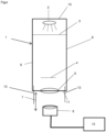
- a collimator housing 1 is shown in the figure.
- the collimator housing 1 consists of four longitudinal walls, the first longitudinal wall 8 and the second longitudinal wall 9 being shown here.
- the two longitudinal walls 8 , 9 have a first end wall 10 at one end and a second end wall 11 at the other end.
- the first end wall 10 includes a light source 2.
- the second end wall 11 includes a lens 5.
- the two longitudinal walls 8, 9 include a mirror 13, the mirror 13 being mounted on the inside of the collimator housing S1 in order to reflect light beams emitting from the light source 2 if necessary.
- the reflection 13 extends out of the collimator housing 1 towards the camera 6.
- the reflection is exclusively on the longitudinal walls 8, 9.
- a diffuser 3 is arranged between a reticle 4 and the light source 2 in the collimator housing 1 .
- the reticle 4 is arranged at an angle to the lens 5 . It is also arranged obliquely to the second end wall 11 or to one of the longitudinal walls 8,9.
- a displacement direction 7 also indicates how a camera 6 can be displaced towards the lens 5 or can be displaced away from the lens 5 . It is also shown that the camera 6 is connected to a computer 12 .
- the computer 12 is designed in such a way that the images recorded by the camera 6 are recorded in an ACTUAL/TARGET comparison and compared with the data stored by the reticle 4 .
- the camera 6 can be moved toward or away from the lens 5 by a device that is not shown in detail.
Landscapes
- Physics & Mathematics (AREA)
- General Physics & Mathematics (AREA)
- Optics & Photonics (AREA)
- Engineering & Computer Science (AREA)
- Signal Processing (AREA)
- Multimedia (AREA)
- Analytical Chemistry (AREA)
- Chemical & Material Sciences (AREA)
- Health & Medical Sciences (AREA)
- General Health & Medical Sciences (AREA)
- Biomedical Technology (AREA)
- Geometry (AREA)
- Length Measuring Devices By Optical Means (AREA)
- Studio Devices (AREA)
Applications Claiming Priority (2)
| Application Number | Priority Date | Filing Date | Title |
|---|---|---|---|
| DE102019105622.5A DE102019105622B4 (de) | 2019-03-06 | 2019-03-06 | Kollimator und Verfahren zum Testen einer Kamera |
| PCT/EP2020/055795 WO2020178366A1 (de) | 2019-03-06 | 2020-03-05 | Kollimator |
Publications (3)
| Publication Number | Publication Date |
|---|---|
| EP3935441A1 EP3935441A1 (de) | 2022-01-12 |
| EP3935441B1 true EP3935441B1 (de) | 2023-08-23 |
| EP3935441C0 EP3935441C0 (de) | 2023-08-23 |
Family
ID=70005577
Family Applications (1)
| Application Number | Title | Priority Date | Filing Date |
|---|---|---|---|
| EP20714118.5A Active EP3935441B1 (de) | 2019-03-06 | 2020-03-05 | Kollimator |
Country Status (8)
| Country | Link |
|---|---|
| US (1) | US12066638B2 (pl) |
| EP (1) | EP3935441B1 (pl) |
| CN (1) | CN113614617A (pl) |
| DE (1) | DE102019105622B4 (pl) |
| ES (1) | ES2964684T3 (pl) |
| HU (1) | HUE064256T2 (pl) |
| PL (1) | PL3935441T3 (pl) |
| WO (1) | WO2020178366A1 (pl) |
Families Citing this family (6)
| Publication number | Priority date | Publication date | Assignee | Title |
|---|---|---|---|---|
| CN114205576A (zh) * | 2020-09-02 | 2022-03-18 | 晋城三赢精密电子有限公司 | 摄像头检测装置 |
| DE102021102246A1 (de) * | 2021-02-01 | 2022-08-04 | Trioptics Gmbh | Vorrichtung und Verfahren zum Messen einer optischen Eigenschaft eines optischen Systems |
| DE102022204539A1 (de) | 2021-05-20 | 2022-11-24 | Magna Electronics Europe Gmbh & Co. Ohg | Verfahren zum Justieren einer Kamera |
| CN215811551U (zh) * | 2021-09-06 | 2022-02-11 | 茂莱(南京)仪器有限公司 | 一种测量光学系统mtf的装置 |
| WO2023074401A1 (ja) * | 2021-10-27 | 2023-05-04 | 京セラ株式会社 | 光学装置及び撮像装置 |
| WO2025147256A1 (en) * | 2024-01-04 | 2025-07-10 | Applied Materials, Inc. | Optical property measurement |
Family Cites Families (34)
| Publication number | Priority date | Publication date | Assignee | Title |
|---|---|---|---|---|
| US1442015A (en) * | 1919-07-08 | 1923-01-09 | American Optical Corp | Gun sight |
| GB1569256A (en) * | 1975-11-14 | 1980-06-11 | Sira Institute | Optical apparatus and method |
| US4199220A (en) * | 1978-09-12 | 1980-04-22 | Casagrande John T | Lens system with reticle and diffuser glass |
| JPS57172221A (en) * | 1981-04-16 | 1982-10-23 | Ricoh Co Ltd | Mtf measuring device for image sensor |
| GB2193817B (en) * | 1986-08-07 | 1990-01-10 | Leech | Collimator device |
| JPH0626375U (ja) * | 1992-08-27 | 1994-04-08 | 日本ビクター株式会社 | ビデオカメラ用コリメータ |
| EP0985140B1 (de) * | 1998-03-27 | 2004-09-15 | Leica Camera AG | Linsen-prüfgerät |
| DE19823844C1 (de) * | 1998-03-27 | 1999-10-14 | Leica Camera Ag | Linsen-Prüfgerät |
| US6025908A (en) * | 1998-05-18 | 2000-02-15 | Houde-Walter; William R. | Alignment of optical elements in telescopes using a laser beam with a holographic projection reticle |
| US6366349B1 (en) * | 1998-05-18 | 2002-04-02 | Lasermax, Inc. | Apparatus for aligning optical elements in response to the display of a reflected reticle image and method of aligning |
| GB0014365D0 (en) * | 2000-06-14 | 2000-08-02 | Digilens Inc | Alignment of holographic diffraction elements |
| DE102004020881B4 (de) * | 2004-04-26 | 2007-03-08 | Deutsches Zentrum für Luft- und Raumfahrt e.V. | Verfahren und Vorrichtung zum geometrischen Kalibrieren von optoelektronischen Messbildkameras |
| DE102004056723B4 (de) * | 2004-11-19 | 2007-04-05 | Deutsches Zentrum für Luft- und Raumfahrt e.V. | Verfahren und Vorrichtung zur geometrischen Kalibrierung eines optoelektronischen Sensorsystems |
| CN100378436C (zh) * | 2004-12-03 | 2008-04-02 | 中国地震局第二监测中心 | 数字水准仪和光学水准仪室内检定装置 |
| BE1016981A3 (fr) * | 2006-02-08 | 2007-11-06 | Fn Herstal Sa | Viseur ameliore a pont rouge mobile. |
| DE102007003681B4 (de) * | 2006-02-10 | 2017-11-30 | Hochschule Bremen | Verfahren und Vorrichtung zur Analyse einer optischen Einrichtung |
| US8675077B2 (en) * | 2008-07-23 | 2014-03-18 | Flir Systems, Inc. | Alignment metrology and resolution measurement system for imaging arrays |
| CN201903291U (zh) * | 2010-12-06 | 2011-07-20 | 西安北方光电有限公司 | 便携式激光三轴测试仪 |
| CN202393958U (zh) * | 2011-05-16 | 2012-08-22 | 于书奎 | 新型平行光管 |
| DE102012200152A1 (de) * | 2012-01-05 | 2013-07-11 | Robert Bosch Gmbh | Vorrichtung und Verfahren zum Vermessen einer Kamera |
| KR101481085B1 (ko) * | 2013-05-16 | 2015-01-14 | (주) 루리텍 | 카메라의 성능 평가 장치 |
| DE102013212097A1 (de) | 2013-06-25 | 2015-01-08 | Cassidian Optronics Gmbh | Kollimatorvorrichtung und Verfahren zur Prüfung und Justierung wenigstens eines optischen Geräts |
| US9535257B2 (en) * | 2014-03-27 | 2017-01-03 | Goodrich Corporation | Multiple collimator unit |
| DE102014209040B4 (de) * | 2014-05-13 | 2019-02-14 | Carl Mahr Holding Gmbh | Verfahren zur Kalibrierung eines Messgerätes |
| JP6512673B2 (ja) * | 2015-03-27 | 2019-05-15 | オリンパス株式会社 | 偏心測定装置及び偏心測定方法 |
| EP3076148B1 (de) | 2015-03-31 | 2019-05-08 | Trioptics GmbH | Vorrichtung und verfahren zum messen von abbildungseigenschaften eines optischen abbildungssystems |
| EP3166312B1 (de) * | 2015-11-06 | 2020-12-30 | Trioptics GmbH | Vorrichtung und verfahren zum justieren und/oder kalibrieren eines multi-kamera moduls sowie verwendung einer solchen vorrichtung |
| JP6561327B2 (ja) * | 2016-03-10 | 2019-08-21 | パナソニックIpマネジメント株式会社 | 光学検査装置、鏡筒の製造方法、および光学検査方法 |
| CN106768872B (zh) * | 2016-11-17 | 2019-08-30 | 孝感华中精密仪器有限公司 | 一种自动焦距测量仪 |
| CN107346050A (zh) * | 2017-07-31 | 2017-11-14 | 美国通用光电公司 | 一种紧凑型光学延迟器 |
| JP7043055B2 (ja) * | 2017-10-26 | 2022-03-29 | 株式会社カツラ・オプト・システムズ | 検査カメラモジュールの調整装置及びその調整方法 |
| CN108278923A (zh) * | 2018-01-29 | 2018-07-13 | 陕西远航光电有限责任公司 | 一种校靶镜(或准直仪)的高同轴度接口装置 |
| EP3896146A4 (en) * | 2018-12-12 | 2022-01-19 | GeneMind Biosciences Company Limited | OPTICAL SYSTEM, METHOD OF CALIBRATION OF AN OPTICAL SYSTEM AND SEQUENCING SYSTEM |
| EP3911982B1 (en) * | 2019-01-20 | 2023-07-05 | Lumus Ltd. | Optical device testing method and apparatus |
-
2019
- 2019-03-06 DE DE102019105622.5A patent/DE102019105622B4/de active Active
-
2020
- 2020-03-05 WO PCT/EP2020/055795 patent/WO2020178366A1/de not_active Ceased
- 2020-03-05 EP EP20714118.5A patent/EP3935441B1/de active Active
- 2020-03-05 HU HUE20714118A patent/HUE064256T2/hu unknown
- 2020-03-05 PL PL20714118.5T patent/PL3935441T3/pl unknown
- 2020-03-05 US US17/436,671 patent/US12066638B2/en active Active
- 2020-03-05 CN CN202080018302.5A patent/CN113614617A/zh active Pending
- 2020-03-05 ES ES20714118T patent/ES2964684T3/es active Active
Also Published As
| Publication number | Publication date |
|---|---|
| DE102019105622A1 (de) | 2020-09-10 |
| US12066638B2 (en) | 2024-08-20 |
| HUE064256T2 (hu) | 2024-03-28 |
| ES2964684T3 (es) | 2024-04-09 |
| PL3935441T3 (pl) | 2024-04-08 |
| CN113614617A (zh) | 2021-11-05 |
| EP3935441A1 (de) | 2022-01-12 |
| US20220137425A1 (en) | 2022-05-05 |
| DE102019105622B4 (de) | 2022-03-17 |
| WO2020178366A1 (de) | 2020-09-10 |
| EP3935441C0 (de) | 2023-08-23 |
Similar Documents
| Publication | Publication Date | Title |
|---|---|---|
| EP3935441B1 (de) | Kollimator | |
| EP2458363B1 (de) | Messung der Positionen von Krümmungsmittelpunkten optischer Flächen eines mehrlinsigen optischen Systems | |
| DE102017131224A1 (de) | Verfahren und Vorrichtung zur Erfassung einer Fokuslage eines Laserstrahls | |
| DE102007003681A1 (de) | Verfahren und Vorrichtung zur Analyse einer optischen Einrichtung | |
| DE102015102111A1 (de) | Mehrkopf-Laseranlage mit Sensoreinheit | |
| DE10234757B4 (de) | Autofokusmodul für Mikroskopbasierte Systeme | |
| WO2022167393A1 (de) | Messvorrichtung und verfahren zum vermessen einer modulationstransferfunktion eines afokalen optischen systems | |
| DE112016006183T5 (de) | Probenform-Messverfahren und Probenform-Messvorrichtung | |
| DE102018115197A1 (de) | Optische Abbildungseinheit und System zur Positionsbestimmung eines beweglichen Objektes im Raum | |
| DE102021118327B4 (de) | Messkamera zur zweidimensionalen Vermessung von Gegenständen | |
| DE102019105627B3 (de) | Kollimator und Verfahren zum Testen einer Kamera | |
| EP1892495A2 (de) | Vorrichtung und Verfahren zur elektronischen Trefferauswertung | |
| DE10037783A1 (de) | Verfahren und Vorrichtung zur Phasenkorrektur von Positions- und Detektionssignalen in der Scanmikroskopie und Scanmikroskop | |
| DE102014010667B4 (de) | Verfahren und Vorrichtung zur Messung der Form einer Wellenfront eines optischen Strahlungsfeldes | |
| DE102022116214A1 (de) | Messkamera und Verfahren zur zweidimensionalen Vermessung von Gegenständen | |
| DE102012219169B4 (de) | Strahlregelungsvorrichtung für einen Beleuchtungsstrahl, optisches System mit einer derartigen Strahlregelungsvorrichung sowie Metrologiesystem mit einem eine solche Strahlregelungsvorrichtung enthaltenden optischen System | |
| DE102019124671B3 (de) | Detektionsanordnung, Autofokusvorrichtung und Fokussierverfahren | |
| DE102013224583A1 (de) | Messanordnung zur Verwendung bei der Trajektorienbestimmung fliegender Objekte | |
| DE102022204539A1 (de) | Verfahren zum Justieren einer Kamera | |
| DE102021118429B4 (de) | Verfahren und Gerät zur 3D-Koordinatenmessung nach dem Autofokusverfahren | |
| DE102012016337B4 (de) | Verfahren zum Bestimmen einer optischen Qualität eines Fotomoduls | |
| DE102017009334B3 (de) | Verfahren zum Prüfen eines optischen Systems | |
| DE102015003392A1 (de) | Optische Triangulations-Sensoranordnung und Linsenanordnung hierfür | |
| EP2966489A1 (de) | Beleuchtungsoptik sowie abbildende optik für ein metrologiesystem für die untersuchung eines objekts mit euv-beleuchtungs- und abbildungslicht sowie metrologiesystem mit einer derartigen beleuchtungsoptik bzw. einer derartigen abbildungsoptik | |
| DE10362244B4 (de) | Verfahren zur Bestimmung der Fokusposition und der Verkippung der Fokusebene bei der Abbildung einer Probe |
Legal Events
| Date | Code | Title | Description |
|---|---|---|---|
| STAA | Information on the status of an ep patent application or granted ep patent |
Free format text: STATUS: UNKNOWN |
|
| STAA | Information on the status of an ep patent application or granted ep patent |
Free format text: STATUS: THE INTERNATIONAL PUBLICATION HAS BEEN MADE |
|
| PUAI | Public reference made under article 153(3) epc to a published international application that has entered the european phase |
Free format text: ORIGINAL CODE: 0009012 |
|
| STAA | Information on the status of an ep patent application or granted ep patent |
Free format text: STATUS: REQUEST FOR EXAMINATION WAS MADE |
|
| 17P | Request for examination filed |
Effective date: 20210917 |
|
| AK | Designated contracting states |
Kind code of ref document: A1 Designated state(s): AL AT BE BG CH CY CZ DE DK EE ES FI FR GB GR HR HU IE IS IT LI LT LU LV MC MK MT NL NO PL PT RO RS SE SI SK SM TR |
|
| DAV | Request for validation of the european patent (deleted) | ||
| DAX | Request for extension of the european patent (deleted) | ||
| REG | Reference to a national code |
Ref country code: DE Ref legal event code: R079 Free format text: PREVIOUS MAIN CLASS: G02B0027360000 Ipc: H04N0017000000 Ref country code: DE Ref legal event code: R079 Ref document number: 502020004860 Country of ref document: DE Free format text: PREVIOUS MAIN CLASS: G02B0027360000 Ipc: H04N0017000000 |
|
| GRAP | Despatch of communication of intention to grant a patent |
Free format text: ORIGINAL CODE: EPIDOSNIGR1 |
|
| STAA | Information on the status of an ep patent application or granted ep patent |
Free format text: STATUS: GRANT OF PATENT IS INTENDED |
|
| RIC1 | Information provided on ipc code assigned before grant |
Ipc: G02B 27/36 20060101ALI20230215BHEP Ipc: G02B 27/62 20060101ALI20230215BHEP Ipc: H04N 17/00 20060101AFI20230215BHEP |
|
| INTG | Intention to grant announced |
Effective date: 20230313 |
|
| GRAS | Grant fee paid |
Free format text: ORIGINAL CODE: EPIDOSNIGR3 |
|
| GRAA | (expected) grant |
Free format text: ORIGINAL CODE: 0009210 |
|
| STAA | Information on the status of an ep patent application or granted ep patent |
Free format text: STATUS: THE PATENT HAS BEEN GRANTED |
|
| AK | Designated contracting states |
Kind code of ref document: B1 Designated state(s): AL AT BE BG CH CY CZ DE DK EE ES FI FR GB GR HR HU IE IS IT LI LT LU LV MC MK MT NL NO PL PT RO RS SE SI SK SM TR |
|
| REG | Reference to a national code |
Ref country code: GB Ref legal event code: FG4D Free format text: NOT ENGLISH |
|
| REG | Reference to a national code |
Ref country code: CH Ref legal event code: EP |
|
| REG | Reference to a national code |
Ref country code: IE Ref legal event code: FG4D Free format text: LANGUAGE OF EP DOCUMENT: GERMAN |
|
| REG | Reference to a national code |
Ref country code: DE Ref legal event code: R096 Ref document number: 502020004860 Country of ref document: DE |
|
| U01 | Request for unitary effect filed |
Effective date: 20230922 |
|
| U07 | Unitary effect registered |
Designated state(s): AT BE BG DE DK EE FI FR IT LT LU LV MT NL PT SE SI Effective date: 20231030 |
|
| PG25 | Lapsed in a contracting state [announced via postgrant information from national office to epo] |
Ref country code: GR Free format text: LAPSE BECAUSE OF FAILURE TO SUBMIT A TRANSLATION OF THE DESCRIPTION OR TO PAY THE FEE WITHIN THE PRESCRIBED TIME-LIMIT Effective date: 20231124 |
|
| PG25 | Lapsed in a contracting state [announced via postgrant information from national office to epo] |
Ref country code: IS Free format text: LAPSE BECAUSE OF FAILURE TO SUBMIT A TRANSLATION OF THE DESCRIPTION OR TO PAY THE FEE WITHIN THE PRESCRIBED TIME-LIMIT Effective date: 20231223 |
|
| PG25 | Lapsed in a contracting state [announced via postgrant information from national office to epo] |
Ref country code: RS Free format text: LAPSE BECAUSE OF FAILURE TO SUBMIT A TRANSLATION OF THE DESCRIPTION OR TO PAY THE FEE WITHIN THE PRESCRIBED TIME-LIMIT Effective date: 20230823 Ref country code: NO Free format text: LAPSE BECAUSE OF FAILURE TO SUBMIT A TRANSLATION OF THE DESCRIPTION OR TO PAY THE FEE WITHIN THE PRESCRIBED TIME-LIMIT Effective date: 20231123 Ref country code: IS Free format text: LAPSE BECAUSE OF FAILURE TO SUBMIT A TRANSLATION OF THE DESCRIPTION OR TO PAY THE FEE WITHIN THE PRESCRIBED TIME-LIMIT Effective date: 20231223 Ref country code: HR Free format text: LAPSE BECAUSE OF FAILURE TO SUBMIT A TRANSLATION OF THE DESCRIPTION OR TO PAY THE FEE WITHIN THE PRESCRIBED TIME-LIMIT Effective date: 20230823 Ref country code: GR Free format text: LAPSE BECAUSE OF FAILURE TO SUBMIT A TRANSLATION OF THE DESCRIPTION OR TO PAY THE FEE WITHIN THE PRESCRIBED TIME-LIMIT Effective date: 20231124 |
|
| REG | Reference to a national code |
Ref country code: SK Ref legal event code: T3 Ref document number: E 43193 Country of ref document: SK |
|
| REG | Reference to a national code |
Ref country code: HU Ref legal event code: AG4A Ref document number: E064256 Country of ref document: HU |
|
| REG | Reference to a national code |
Ref country code: ES Ref legal event code: FG2A Ref document number: 2964684 Country of ref document: ES Kind code of ref document: T3 Effective date: 20240409 |
|
| PG25 | Lapsed in a contracting state [announced via postgrant information from national office to epo] |
Ref country code: SM Free format text: LAPSE BECAUSE OF FAILURE TO SUBMIT A TRANSLATION OF THE DESCRIPTION OR TO PAY THE FEE WITHIN THE PRESCRIBED TIME-LIMIT Effective date: 20230823 Ref country code: CZ Free format text: LAPSE BECAUSE OF FAILURE TO SUBMIT A TRANSLATION OF THE DESCRIPTION OR TO PAY THE FEE WITHIN THE PRESCRIBED TIME-LIMIT Effective date: 20230823 |
|
| U20 | Renewal fee for the european patent with unitary effect paid |
Year of fee payment: 5 Effective date: 20240326 |
|
| REG | Reference to a national code |
Ref country code: DE Ref legal event code: R097 Ref document number: 502020004860 Country of ref document: DE |
|
| PLBE | No opposition filed within time limit |
Free format text: ORIGINAL CODE: 0009261 |
|
| STAA | Information on the status of an ep patent application or granted ep patent |
Free format text: STATUS: NO OPPOSITION FILED WITHIN TIME LIMIT |
|
| 26N | No opposition filed |
Effective date: 20240524 |
|
| REG | Reference to a national code |
Ref country code: CH Ref legal event code: PL |
|
| PG25 | Lapsed in a contracting state [announced via postgrant information from national office to epo] |
Ref country code: MC Free format text: LAPSE BECAUSE OF FAILURE TO SUBMIT A TRANSLATION OF THE DESCRIPTION OR TO PAY THE FEE WITHIN THE PRESCRIBED TIME-LIMIT Effective date: 20230823 |
|
| PG25 | Lapsed in a contracting state [announced via postgrant information from national office to epo] |
Ref country code: MC Free format text: LAPSE BECAUSE OF FAILURE TO SUBMIT A TRANSLATION OF THE DESCRIPTION OR TO PAY THE FEE WITHIN THE PRESCRIBED TIME-LIMIT Effective date: 20230823 |
|
| PG25 | Lapsed in a contracting state [announced via postgrant information from national office to epo] |
Ref country code: IE Free format text: LAPSE BECAUSE OF NON-PAYMENT OF DUE FEES Effective date: 20240305 |
|
| PG25 | Lapsed in a contracting state [announced via postgrant information from national office to epo] |
Ref country code: IE Free format text: LAPSE BECAUSE OF NON-PAYMENT OF DUE FEES Effective date: 20240305 Ref country code: CH Free format text: LAPSE BECAUSE OF NON-PAYMENT OF DUE FEES Effective date: 20240331 |
|
| PGFP | Annual fee paid to national office [announced via postgrant information from national office to epo] |
Ref country code: RO Payment date: 20250304 Year of fee payment: 6 |
|
| PGFP | Annual fee paid to national office [announced via postgrant information from national office to epo] |
Ref country code: HU Payment date: 20250331 Year of fee payment: 6 |
|
| PGFP | Annual fee paid to national office [announced via postgrant information from national office to epo] |
Ref country code: PL Payment date: 20250227 Year of fee payment: 6 |
|
| PGFP | Annual fee paid to national office [announced via postgrant information from national office to epo] |
Ref country code: SK Payment date: 20250227 Year of fee payment: 6 Ref country code: GB Payment date: 20250324 Year of fee payment: 6 |
|
| U20 | Renewal fee for the european patent with unitary effect paid |
Year of fee payment: 6 Effective date: 20250324 |
|
| PGFP | Annual fee paid to national office [announced via postgrant information from national office to epo] |
Ref country code: ES Payment date: 20250416 Year of fee payment: 6 |
|
| PG25 | Lapsed in a contracting state [announced via postgrant information from national office to epo] |
Ref country code: CY Free format text: LAPSE BECAUSE OF FAILURE TO SUBMIT A TRANSLATION OF THE DESCRIPTION OR TO PAY THE FEE WITHIN THE PRESCRIBED TIME-LIMIT; INVALID AB INITIO Effective date: 20200305 |
|
| PG25 | Lapsed in a contracting state [announced via postgrant information from national office to epo] |
Ref country code: TR Free format text: LAPSE BECAUSE OF FAILURE TO SUBMIT A TRANSLATION OF THE DESCRIPTION OR TO PAY THE FEE WITHIN THE PRESCRIBED TIME-LIMIT Effective date: 20230823 |