EP3934393A1 - Soldering apparatus and method of detecting failures of gasket - Google Patents
Soldering apparatus and method of detecting failures of gasket Download PDFInfo
- Publication number
- EP3934393A1 EP3934393A1 EP21173525.3A EP21173525A EP3934393A1 EP 3934393 A1 EP3934393 A1 EP 3934393A1 EP 21173525 A EP21173525 A EP 21173525A EP 3934393 A1 EP3934393 A1 EP 3934393A1
- Authority
- EP
- European Patent Office
- Prior art keywords
- seal
- gasket
- gas
- sealed space
- furnace body
- Prior art date
- Legal status (The legal status is an assumption and is not a legal conclusion. Google has not performed a legal analysis and makes no representation as to the accuracy of the status listed.)
- Granted
Links
Images




Classifications
-
- B—PERFORMING OPERATIONS; TRANSPORTING
- B23—MACHINE TOOLS; METAL-WORKING NOT OTHERWISE PROVIDED FOR
- B23K—SOLDERING OR UNSOLDERING; WELDING; CLADDING OR PLATING BY SOLDERING OR WELDING; CUTTING BY APPLYING HEAT LOCALLY, e.g. FLAME CUTTING; WORKING BY LASER BEAM
- B23K3/00—Tools, devices or special appurtenances for soldering, e.g. brazing, or unsoldering, not specially adapted for particular methods
-
- B—PERFORMING OPERATIONS; TRANSPORTING
- B23—MACHINE TOOLS; METAL-WORKING NOT OTHERWISE PROVIDED FOR
- B23K—SOLDERING OR UNSOLDERING; WELDING; CLADDING OR PLATING BY SOLDERING OR WELDING; CUTTING BY APPLYING HEAT LOCALLY, e.g. FLAME CUTTING; WORKING BY LASER BEAM
- B23K3/00—Tools, devices or special appurtenances for soldering, e.g. brazing, or unsoldering, not specially adapted for particular methods
- B23K3/08—Auxiliary devices therefor
-
- B—PERFORMING OPERATIONS; TRANSPORTING
- B23—MACHINE TOOLS; METAL-WORKING NOT OTHERWISE PROVIDED FOR
- B23K—SOLDERING OR UNSOLDERING; WELDING; CLADDING OR PLATING BY SOLDERING OR WELDING; CUTTING BY APPLYING HEAT LOCALLY, e.g. FLAME CUTTING; WORKING BY LASER BEAM
- B23K1/00—Soldering, e.g. brazing, or unsoldering
- B23K1/0008—Soldering, e.g. brazing, or unsoldering specially adapted for particular articles or work
- B23K1/0016—Soldering of electronic components
-
- B—PERFORMING OPERATIONS; TRANSPORTING
- B23—MACHINE TOOLS; METAL-WORKING NOT OTHERWISE PROVIDED FOR
- B23K—SOLDERING OR UNSOLDERING; WELDING; CLADDING OR PLATING BY SOLDERING OR WELDING; CUTTING BY APPLYING HEAT LOCALLY, e.g. FLAME CUTTING; WORKING BY LASER BEAM
- B23K1/00—Soldering, e.g. brazing, or unsoldering
- B23K1/008—Soldering within a furnace
-
- B—PERFORMING OPERATIONS; TRANSPORTING
- B23—MACHINE TOOLS; METAL-WORKING NOT OTHERWISE PROVIDED FOR
- B23K—SOLDERING OR UNSOLDERING; WELDING; CLADDING OR PLATING BY SOLDERING OR WELDING; CUTTING BY APPLYING HEAT LOCALLY, e.g. FLAME CUTTING; WORKING BY LASER BEAM
- B23K3/00—Tools, devices or special appurtenances for soldering, e.g. brazing, or unsoldering, not specially adapted for particular methods
- B23K3/04—Heating appliances
-
- G—PHYSICS
- G01—MEASURING; TESTING
- G01M—TESTING STATIC OR DYNAMIC BALANCE OF MACHINES OR STRUCTURES; TESTING OF STRUCTURES OR APPARATUS, NOT OTHERWISE PROVIDED FOR
- G01M3/00—Investigating fluid-tightness of structures
- G01M3/02—Investigating fluid-tightness of structures by using fluid or vacuum
-
- G—PHYSICS
- G01—MEASURING; TESTING
- G01M—TESTING STATIC OR DYNAMIC BALANCE OF MACHINES OR STRUCTURES; TESTING OF STRUCTURES OR APPARATUS, NOT OTHERWISE PROVIDED FOR
- G01M3/00—Investigating fluid-tightness of structures
- G01M3/02—Investigating fluid-tightness of structures by using fluid or vacuum
- G01M3/04—Investigating fluid-tightness of structures by using fluid or vacuum by detecting the presence of fluid at the leakage point
- G01M3/20—Investigating fluid-tightness of structures by using fluid or vacuum by detecting the presence of fluid at the leakage point using special tracer materials, e.g. dye, fluorescent material, radioactive material
-
- G—PHYSICS
- G01—MEASURING; TESTING
- G01M—TESTING STATIC OR DYNAMIC BALANCE OF MACHINES OR STRUCTURES; TESTING OF STRUCTURES OR APPARATUS, NOT OTHERWISE PROVIDED FOR
- G01M3/00—Investigating fluid-tightness of structures
- G01M3/02—Investigating fluid-tightness of structures by using fluid or vacuum
- G01M3/26—Investigating fluid-tightness of structures by using fluid or vacuum by measuring rate of loss or gain of fluid, e.g. by pressure-responsive devices, by flow detectors
-
- G—PHYSICS
- G01—MEASURING; TESTING
- G01M—TESTING STATIC OR DYNAMIC BALANCE OF MACHINES OR STRUCTURES; TESTING OF STRUCTURES OR APPARATUS, NOT OTHERWISE PROVIDED FOR
- G01M3/00—Investigating fluid-tightness of structures
- G01M3/02—Investigating fluid-tightness of structures by using fluid or vacuum
- G01M3/26—Investigating fluid-tightness of structures by using fluid or vacuum by measuring rate of loss or gain of fluid, e.g. by pressure-responsive devices, by flow detectors
- G01M3/28—Investigating fluid-tightness of structures by using fluid or vacuum by measuring rate of loss or gain of fluid, e.g. by pressure-responsive devices, by flow detectors for pipes, cables or tubes; for pipe joints or seals; for valves ; for welds
- G01M3/30—Investigating fluid-tightness of structures by using fluid or vacuum by measuring rate of loss or gain of fluid, e.g. by pressure-responsive devices, by flow detectors for pipes, cables or tubes; for pipe joints or seals; for valves ; for welds using progressive displacement of one fluid by another
-
- H—ELECTRICITY
- H05—ELECTRIC TECHNIQUES NOT OTHERWISE PROVIDED FOR
- H05K—PRINTED CIRCUITS; CASINGS OR CONSTRUCTIONAL DETAILS OF ELECTRIC APPARATUS; MANUFACTURE OF ASSEMBLAGES OF ELECTRICAL COMPONENTS
- H05K3/00—Apparatus or processes for manufacturing printed circuits
- H05K3/30—Assembling printed circuits with electric components, e.g. with resistors
- H05K3/32—Assembling printed circuits with electric components, e.g. with resistors electrically connecting electric components or wires to printed circuits
- H05K3/34—Assembling printed circuits with electric components, e.g. with resistors electrically connecting electric components or wires to printed circuits by soldering
- H05K3/3494—Heating processes for reflow soldering
-
- B—PERFORMING OPERATIONS; TRANSPORTING
- B23—MACHINE TOOLS; METAL-WORKING NOT OTHERWISE PROVIDED FOR
- B23K—SOLDERING OR UNSOLDERING; WELDING; CLADDING OR PLATING BY SOLDERING OR WELDING; CUTTING BY APPLYING HEAT LOCALLY, e.g. FLAME CUTTING; WORKING BY LASER BEAM
- B23K2101/00—Articles made by soldering, welding or cutting
- B23K2101/36—Electric or electronic devices
- B23K2101/42—Printed circuits
Definitions
- the soldering apparatuses generally include the sealing gaskets that mainly prevent the in-furnace air from leaking to the outside of the apparatuses.
- the gaskets to which the failures such as the deterioration by the heat have occurred may cause the leakage of the in-furnace air.
- the first seal 12 and the second seal 14 respectively have a first sealing surface 12a and a second sealing surface 14a to be held in contact with the upper furnace body 110A.
- the first sealing surface 12a and the second sealing surface 14a each have a semi-circular shape in cross-section.
- the first sealing surface 12a and the second sealing surface 14a may each have an arbitrary protruding shape.
- the gas to be supplied by the gas supply apparatus 32 is not limited to the inert gas, and may be an arbitrary gas. However, in order that influence on an environment in the processing chamber 110D is suppressed even in a case where the gas filling the sealed space S1 leaks into the processing chamber 110D, the gas is desirably the inert gas such as nitrogen.
- the gas in the sealed space S1 can be prevented from leaking through the through-hole 16a formed in the fixation portion 16.
Landscapes
- Engineering & Computer Science (AREA)
- Mechanical Engineering (AREA)
- Physics & Mathematics (AREA)
- General Physics & Mathematics (AREA)
- Manufacturing & Machinery (AREA)
- Microelectronics & Electronic Packaging (AREA)
- Electric Connection Of Electric Components To Printed Circuits (AREA)
- Examining Or Testing Airtightness (AREA)
- Furnace Details (AREA)
Abstract
Description
- The present invention relates to a soldering apparatus and a method of detecting failures of a gasket.
- A reflow apparatus has been known as an example of apparatuses that solder electronic components to printed circuit boards. In the reflow apparatus, for ease of maintenance, a structure in which a housing of an upper furnace body is superimposed in a separable manner on a lower furnace body has been employed. A superimposed part of the furnace bodies is sealed with a gasket such that in-furnace air is prevented from leaking to the outside. By preventing the in-furnace air from leaking to the outside, in-furnace heating efficiency can be maintained. In addition, N2 reflow apparatuses including furnaces in which a nitrogen atmosphere is maintained for increasing soldering efficiency also have been used. Also in the N2 reflow apparatuses, the nitrogen atmosphere in the furnace can be maintained by preventing the in-furnace air from leaking to the outside. As an example of such reflow apparatuses including the gaskets, an apparatus disclosed in Japanese Patent Application Laid-open No.
2019-166532 - PTL 1: Japanese Patent Application Laid-open No.
2019-166532 - In the reflow apparatus, boards to which solder paste has been printed in advance are transported into and then heated in a reflow furnace of the reflow apparatus. The gasket that prevents the leakage of the in-furnace air is deteriorated along with heating of the in-furnace air. In addition, when the boards are heated, flux contained in the solder paste is vaporized into flux fumes that waft in the reflow furnace. Adhesion of these flux fumes to the gasket causes corrosion of the gasket. The gasket to which failures such as the deterioration by the heat and the corrosion by the adhesion of the flux fumes have occurred may cause the leakage of the in-furnace air.
- In addition, as an example of soldering apparatuses other than the reflow apparatus, there may be mentioned a jet soldering apparatus including a jet solder bath. In this jet soldering apparatus, boards to which flux has been applied in advance are heated during a process of being transported to the jet solder bath, and then soldered with molten solder that is jetted in the jet solder bath. In the heating of the boards and the soldering in the jet solder bath, the flux is vaporized into the flux fumes. As a countermeasure, also in the jet soldering apparatus, the gasket that prevents the in-furnace air and the flux fumes from leaking to the outside of the apparatus is provided as in the reflow apparatus. In such ways, the soldering apparatuses generally include the sealing gaskets that mainly prevent the in-furnace air from leaking to the outside of the apparatuses. However, the gaskets to which the failures such as the deterioration by the heat have occurred may cause the leakage of the in-furnace air.
- In the reflow apparatus disclosed in Japanese Patent Application Laid-open No.
2019-166532 2019-166532 - In addition, the reflow apparatus disclosed in Japanese Patent Application Laid-open No.
2019-166532 - The present invention has been made to solve the related-art problems as described above, and an object thereof is to detect failures of a gasket more promptly. In addition, another object of the present invention is to determine whether or not abnormalities of oxygen concentration in a furnace (in processing chamber) have been caused by the failures of the gasket.
- The present invention achieves at least one of the objects.
- According to a first aspect, there is provided a soldering apparatus. This soldering apparatus includes:
- a furnace body including a processing chamber in which boards are processed;
- a gasket
- provided at least to a part of the furnace body, and
- configured to seal the furnace body;
- a sealed space
- isolated from the processing chamber, and
- defined by the furnace body and the gasket;
- a gas supply apparatus configured to supply a first gas into the sealed space; and
- a measuring apparatus configured to measure one of
- pressure in the sealed space and
- concentration of a second gas in the sealed space.
- According to the first aspect, the one of the pressure and the concentration of the second gas in the sealed space can be measured after the sealed space has been filled with the first gas. Thus, in a case where the one of the pressure and the concentration of the second gas in the sealed space reaches a predetermined threshold, it can be grasped that failures of the gasket have occurred. Further, the sealed space that is defined by the gasket is located to separate the processing chamber and the outside of the furnace, and in addition, can be more easily reduced in volume than the processing chamber. Thus, unlike the related art, leakage of the gas from the sealed space that is narrower than the processing chamber can be detected before occurrence of abnormalities of the concentration of the gas such as oxygen in the processing chamber. As a result, the failures of the gasket can be more promptly detected.
- According to a second aspect, the soldering apparatus according to the first aspect, in which the first gas is nitrogen.
- According to the second aspect, even in a case where nitrogen that has filled the sealed space leaks into the processing chamber (into furnace), influence on an environment in the processing chamber can be suppressed.
- According to a third aspect, the soldering apparatus according to the first or second aspect, in which the second gas is oxygen.
- According to the third aspect, when an atmosphere in the processing chamber is monitored with an oxygen meter, this oxygen meter is connected to an inside of the sealed space. With this, measurement in the processing chamber and measurement in the sealed space can be performed alternately to each other. Thus, the number of components (number of measurement apparatuses) necessary for the soldering apparatus can be suppressed from increasing.
- According to a fourth aspect, the soldering apparatus according to the first aspect, in which the first gas and the second gas are gases of the same type.
- According to the fourth aspect, if the second gas of the same type as that of the first gas decreases to a predetermined value after the first gas has filled the sealed space, it can be determined that the failures of the gasket have occurred.
- According to a fifth aspect, the soldering apparatus according to any one of the first to fourth aspects, in which
the gasket includes - a first seal,
- a second seal that is arranged away from the first seal,
- a third seal that effects sealing between the first seal and the second seal, and
- a fourth seal
- that effects the sealing between the first seal and the second seal, and
- that is arranged away from the third seal, and
the sealed space is defined at least by
- the furnace body,
- the first seal,
- the second seal,
- the third seal, and
- the fourth seal.
- According to the fifth aspect, the furnace body is sealed with the plurality of seals. Thus, even in a case where any of these seals is deteriorated, the furnace body can remain sealed by other ones of the seals.
- According to a sixth aspect, the soldering apparatus according to the fifth aspect, in which
the third seal is arranged between respective end portions on one side of the first seal and the second seal, and
the fourth seal is arranged between respective end portions on another side of the first seal and the second seal. - According to the sixth aspect, the sealed space can be elongated along a transport direction of the boards. Thus, failures can be detected substantially all over the first seal and the second seal.
- According to a seventh aspect, the soldering apparatus according to any one of the first to sixth aspects further including a control apparatus capable of communicating with the measuring apparatus, in which
the control apparatus is configured to determine whether or not the one of the pressure and the concentration received from the measuring apparatus has reached a predetermined threshold. - According to the seventh aspect, when the one of pressure in the sealed space and the concentration of the second gas in a case where the failures of the gasket have occurred is set to a predetermined threshold, the control apparatus is enabled to determine that the failures of the gasket have occurred.
- According to an eighth aspect, there is provided a method of detecting failures of a gasket that seals a furnace body including a processing chamber in which boards are processed. This method of detecting the failures of the gasket includes:
- supplying a first gas into a sealed space
- isolated from the processing chamber, and
- defined by the furnace body and the gasket;
- measuring one of
- pressure in the sealed space and
- concentration of a second gas in the sealed space; and
- determining whether or not the one of the pressure and the concentration of the second gas has reached a predetermined threshold.
- According to the eighth aspect, the one of the pressure and the concentration of the second gas in the sealed space can be measured after the first gas has been supplied into the sealed space. Thus, in a case where the one of the pressure and the concentration of the second gas in the sealed space reaches a predetermined threshold, it can be grasped that failures of the gasket have occurred. Further, the sealed space that is defined by the gasket is located to separate the processing chamber and the outside of the furnace, and in addition, can be more easily reduced in volume than the processing chamber. Thus, unlike the related art, leakage of the gas from the sealed space that is narrower than the processing chamber can be detected before occurrence of abnormalities of the concentration of the gas such as oxygen in the processing chamber. As a result, the failures of the gasket can be more promptly detected.
- According to a ninth aspect, the method according to the eighth aspect, in which the first gas is nitrogen.
- According to the ninth aspect, even in a case where nitrogen that has filled the sealed space leaks into the processing chamber, influence on an environment in the processing chamber can be suppressed.
- According to a tenth aspect, the method according to the eighth or ninth aspect, in which the second gas is oxygen.
- According to the tenth aspect, when an atmosphere in the processing chamber is monitored with an oxygen meter, this oxygen meter is connected to an inside of the sealed space. With this, measurement in the processing chamber and measurement in the sealed space can be performed alternately to each other. Thus, the number of components (number of measurement apparatuses) necessary for implementing the method of detecting the failures of the gasket can be suppressed from increasing.
-
Fig. 1 is a schematic top view of a reflow apparatus according to an embodiment of the present invention; -
Fig. 2 is a schematic side view of the reflow apparatus according to the embodiment of the present invention; -
Fig. 3 is a top view of a gasket according to the embodiment of the present invention; -
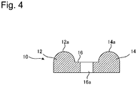
Fig. 4 is a cross-sectional view of the gasket, which is taken along arrows 4-4 inFig. 3 ; -
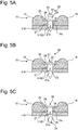
Fig. 5A is a view illustrating a procedure for attaching the gasket with use of push rivets; -
Fig. 5B is another view illustrating the procedure for attaching the gasket with use of the push rivets; -
Fig. 5C is a still another view illustrating the procedure for attaching the gasket with use of the push rivets; -
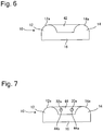
Fig. 6 is a side view of the gasket, which is taken along arrows 6-6 inFig. 3 ; -
Fig. 7 is a side view of thegasket 10, which is taken along arrows 7-7; -
Fig. 8 is a flowchart showing a method of detecting failures of the gasket in the reflow apparatus according to the embodiment of the present invention; -
Fig. 9 is a flowchart showing another method of detecting the failures of the gasket in the reflow apparatus according to the embodiment of the present invention; and -
Fig. 10 is a top view illustrating another example of the gasket according to the embodiment of the present invention. - Now, an embodiment of the present invention is described with reference to the drawings. In the drawings referred to below, the same or corresponding components are denoted by the same reference symbols to omit redundant description thereof. Note that, although a reflow apparatus is exemplified as a soldering apparatus of the present invention in the embodiment described below, the soldering apparatus is not limited thereto, and any soldering apparatus in which the gaskets are used as described above may be encompassed within the scope of the present invention.
-
Fig. 1 is a schematic top view of the reflow apparatus according to this embodiment.Fig. 2 is a schematic side view of the reflow apparatus according to this embodiment. As illustrated inFig. 1 andFig. 2 , thisreflow apparatus 100 includes afurnace body 110, a carry-inport 120, a carry-outport 130, and acontrol apparatus 140. Thefurnace body 110 includes therein aprocessing chamber 110D in which boards (not shown) are processed. The carry-inport 120 is an inlet for allowing the boards to which solder paste has been applied (not shown) to be carried into theprocessing chamber 110D in thefurnace body 110. The carry-outport 130 is an outlet for allowing the heated boards (not shown) to be carried out of theprocessing chamber 110D in thefurnace body 110. Thereflow apparatus 100 according to this embodiment need not necessarily include the single carry-inport 120 and the single carry-outport 130, and may, for example, include two or more carry-inports 120 and as many carry-outports 130 such that a larger number of boards are processed at the same time. - The
reflow apparatus 100 includes a transport conveyor (not shown) for transporting the boards, which have been fed through the carry-inport 120, to the carry-outport 130. Thefurnace body 110 includes therein a configuration that heats, from above and below, the boards having been carried in through the carry-inport 120, and then cools the heated boards. Specifically, for example, thefurnace body 110 includes therein a plurality of heating zones and at least one cooling zone arranged in line. The boards that have been carried in through the carry-inport 120 are transported toward the carry-outport 130 at a predetermined speed. The boards are preliminarily heated at a preliminary heating portion in one of the heating zones, and then heated to a predetermined temperature at a main heating portion in another one of the heating zones. During these processes, the solder paste on the boards is molten, and flux fumes are generated at the time when the solder paste is molten. In the cooling zone, the boards are rapidly cooled to solidify the solder. - The
control apparatus 140 is configured, for example, to be capable of controlling an operation of thereflow apparatus 100 according to this embodiment, and is communicably connected to the transport conveyor, the heating zones, and the cooling zone (none of which is shown). Thecontrol apparatus 140 may include, for example, a CPU, a memory that stores operating programs, and a PLC (Programmable Logic Controller) that includes an input/output unit. In addition, thecontrol apparatus 140 is configured to be capable of controlling operations of a measuringapparatus 30 and agas supply apparatus 32 described below. - The
reflow apparatus 100 may have thegas supply apparatus 32 configured to supply an inert gas such as nitrogen (corresponding to an example of a first gas) into theprocessing chamber 110D, and the measuringapparatus 30. The measuringapparatus 30 may be a gas concentration sensor that measures concentration of a gas such as oxygen (corresponding to an example of a secondary gas). In thereflow apparatus 100, thegas supply apparatus 32 supplies the inert gas such as nitrogen such that oxygen concentration in theprocessing chamber 110D is reduced. The measuringapparatus 30 measures the oxygen concentration in theprocessing chamber 110D. Data of the oxygen concentration measured by the measuringapparatus 30 may be transmitted, for example, to thecontrol apparatus 140 or an external computer other than thecontrol apparatus 140. This enables an operator to check whether an atmosphere in theprocessing chamber 110D is normal. - As illustrated in
Fig. 2 , thefurnace body 110 includes anupper furnace body 110A and alower furnace body 110B. Theupper furnace body 110A and thelower furnace body 110B are coupled to each other with, for example, hinges, and theupper furnace body 110A is configured to be openable/closable on its one side relative to thelower furnace body 110B such that internal maintenance and the like can be performed. In this embodiment, in order that in-furnace air is prevented from leaking through a superimposition plane between theupper furnace body 110A and thelower furnace body 110B, as illustrated inFig. 1 , agasket 10 is provided to at least one of theupper furnace body 110A and thelower furnace body 110B. Thegasket 10 may be formed of an arbitrary sealing material such as a silicone sponge. Specifically, in this embodiment, along a direction in which the carry-inport 120 and the carry-outport 130 are linked to each other (transport direction of the boards), thegasket 10 is provided along both edges of opening portions of thelower furnace body 110B. This prevents the leakage of the in-furnace air under a state in which theupper furnace body 110A and thelower furnace body 110B are closed to each other. Thus, during the process of heating the boards, the flux fumes generated in thefurnace body 110 also can be suppressed from flowing to an outside of thefurnace body 110. Note that, thegasket 10 may be provided to theupper furnace body 110A. - In the
reflow apparatus 100 as described above in this embodiment, thegasket 10 is deteriorated along with heating of the in-furnace air. In addition, adhesion of the flux fumes causes corrosion of thegasket 10. Thegasket 10 to which failures such as the deterioration by the heat and the corrosion by the adhesion of the flux fumes have occurred may cause the leakage of the in-furnace air. As a countermeasure, it is conceivable to detect the leakage of the in-furnace air by measuring concentration of a specific one of the gases in theprocessing chamber 110D of thefurnace body 110. However, it may take time to determine whether or not the concentration of the specific one of the in-furnace gases has reached a predetermined value as a result of the occurrence of the failures of thegasket 10. - In view of such circumstances, in the
reflow apparatus 100 according to this embodiment, a sealed space isolated from theprocessing chamber 110D is formed with use of thegasket 10 such that the failures of thegasket 10 are more promptly detected.Fig. 3 is a top view of thegasket 10 according to this embodiment.Fig. 4 is a cross-sectional view of thegasket 10, which is taken along arrows 4-4 inFig. 3 . As illustrated inFig. 3 andFig. 4 , thegasket 10 according to this embodiment includes afirst seal 12, asecond seal 14, and afixation portion 16. Thefirst seal 12, thesecond seal 14, and thefixation portion 16 extend along the direction in which the carry-inport 120 and the carry-outport 130 illustrated inFig. 1 are linked to each other (transport direction of the boards), that is, along each of both the edges of the opening portions of theupper furnace body 110A and thelower furnace body 110B. Thefirst seal 12 and thesecond seal 14 are arranged away from each other, and thefixation portion 16 is located therebetween. - As illustrated in
Fig. 4 , thefirst seal 12 and thesecond seal 14 respectively have afirst sealing surface 12a and asecond sealing surface 14a to be held in contact with theupper furnace body 110A. As illustrated inFig. 4 , in this embodiment, thefirst sealing surface 12a and thesecond sealing surface 14a each have a semi-circular shape in cross-section. Alternatively, thefirst sealing surface 12a and thesecond sealing surface 14a may each have an arbitrary protruding shape. - Although the
first seal 12 and thesecond seal 14 may have thicknesses and shapes different from each other, as illustrated inFig. 4 , in this embodiment, thefirst seal 12 and thesecond seal 14 each have substantially the same thickness and substantially the same shape. This enables substantially-uniform pressure application to thefirst seal 12 and thesecond seal 14 under the state in which thefurnace body 110 is closed. As a result, degrees of deterioration of thefirst seal 12 and thesecond seal 14 can be further equalized to each other. - The
fixation portion 16 is a plate-like part to be coupled to thefirst seal 12 and thesecond seal 14. In other words, thefixation portion 16 has a function to couple thefirst seal 12 and thesecond seal 14 integrally to each other. Thefixation portion 16 is located between thefirst seal 12 and thesecond seal 14, and extends in the same direction as a direction in which thefirst seal 12 and thesecond seal 14 extend. As illustrated inFig. 3 , thefixation portion 16 has a plurality of through-holes 16a. As described below, by inserting push rivets into the through-holes 16a, thegasket 10 can be fixed in an attachable/detachable manner to thefurnace body 110. - In addition, as illustrated in
Fig. 4 , thefixation portion 16 is thinner than each of thefirst seal 12 and thesecond seal 14. This configuration prevents the push rivets arranged in thefixation portion 16 from protruding higher than thefirst seal 12 and thesecond seal 14 under the state in which thefurnace body 110 is sealed. In this way, this configuration does not physically influence the sealing of thefurnace body 110. - Next, a procedure for attaching the
gasket 10 illustrated inFig. 3 andFig. 4 to thefurnace body 110 is described.Fig. 5A, Fig. 5B, and Fig. 5C are views illustrating the procedure for attaching thegasket 10 with use of the push rivets.Fig. 5A to Fig. 5C illustrate a part of thefurnace body 110, whereholes 110C that allow the push rivets to be inserted thereinto are provided at corresponding parts in thefurnace body 110. As illustrated inFig. 5A , apush rivet 20 includes apin 21 and arivet body 25. Thepin 21 includes ahead portion 22 and ashaft portion 23. Theshaft portion 23 includes a tapered part such that a diameter of theshaft portion 23 gradually increases toward a distal end of thepin 21. Therivet body 25 includes aflange portion 26 and aleg portion 27 extending from theflange portion 26. Theflange portion 26 has a hole that allows thepin 21 to be inserted thereinto, and theleg portion 27 is formed into a substantially cylindrical shape so as to allow thepin 21 to be inserted thereinto. Theleg portion 27 includesnotch portions 27a at an end portion on the distal end side of thepin 21. - The
gasket 10 is attached to thefurnace body 110 as follows. First, thegasket 10 is arranged in thefurnace body 110, and as illustrated inFig. 5A , thepush rivet 20 is inserted into the through-hole 16a of thegasket 10 and thehole 110C of thefurnace body 110. Under the state illustrated inFig. 5A , thegasket 10 has not yet been fixed to thefurnace body 110. - Then, as illustrated in
Fig. 5B , an operator or the like pushes thehead portion 22 of thepin 21 into therivet body 25. At this time, theshaft portion 23 of thepin 21 causes theleg portion 27 of therivet body 25 to radially expand. With this, theleg portion 27 of therivet body 25 is pressed against an inner peripheral surface of thehole 110C of thefurnace body 110. In this way, thepush rivet 20 is fixed to thefurnace body 110. Thegasket 10 is pressed against thefurnace body 110 by theflange portion 26 of therivet body 25. In this way, thegasket 10 is fixed to thefurnace body 110 by thepush rivet 20. - In order to detach the
gasket 10 from thefurnace body 110, as illustrated inFig. 5C , thepin 21 of thepush rivet 20 is further pushed in toward the distal end. As a result, a relatively radially-small part of thepin 21 comes to an inside of therivet body 25. With this, theleg portion 27 of therivet body 25 is radially shrunk (enters a straight state). In this state, thepush rivet 20 is pulled out of the through-hole 16a of thegasket 10 and thehole 110C of thefurnace body 110. In this way, the fixation of thegasket 10 is released. - As described above, the
gasket 10 is fixed in the attachable/detachable manner to thefurnace body 110 by thepush rivet 20. Thepush rivet 20 can be easily attached and detached by the operator, and hence thegasket 10 can be easily attached to and detached from thefurnace body 110. Further, in this embodiment, by inserting thepush rivet 20 into the through-hole 16a of thegasket 10, theflange portion 26 is brought into direct contact with thegasket 10, whereby thegasket 10 can be fixed to thefurnace body 110. Still further, in this fixed state, by further pushing in thepin 21 of thepush rivet 20 toward the distal end, and then by pulling thepush rivet 20 out of the through-hole 16a of thegasket 10 and thehole 110C of thefurnace body 110, the fixation of thegasket 10 is released. With this, efficiency at the time of the operation to attach thegasket 10 and maintainability at the time of replacing thegasket 10 can be increased to be higher than those in the related-art fixation methods including using screws or bond. - The
first seal 12 and thesecond seal 14 need not necessarily be fixed with thepush rivet 20, and may be fixed to thefurnace body 110 with an arbitrary adhesive. In addition, in that case, the through-hole 16a of thefixation portion 16 may be omitted, or thefixation portion 16 itself may be omitted. In other words, thefirst seal 12 and thesecond seal 14 may be fixed as independent members to thefurnace body 110 with the arbitrary adhesive. - Referring back to
Fig. 3 , thegasket 10 is described in detail. As illustrated inFig. 3 , thegasket 10 further includes athird seal 42 and afourth seal 44.Fig. 6 is a side view of thegasket 10, which is taken along arrows 6-6 inFig. 3 .Fig. 7 is a side view of thegasket 10, which is taken along arrows 7-7. Thethird seal 42 and thefourth seal 44 are arranged between thefirst seal 12 and thesecond seal 14, and are configured to effect sealing between thefirst seal 12 and thesecond seal 14. Similar to thefirst seal 12 and thesecond seal 14, thethird seal 42 and thefourth seal 44 may be formed of the arbitrary sealing material such as the silicone sponge. Thethird seal 42 and thefourth seal 44 may each have an arbitrary shape as long as the sealing between thefirst seal 12 and thesecond seal 14 can be effected. In the example illustrated inFig. 6 and Fig. 7 , thethird seal 42 and thefourth seal 44 each have such a shape that fills a gap between thefirst seal 12 and thesecond seal 14. - As illustrated in
Fig. 3 , thethird seal 42 and thefourth seal 44 are arranged away from each other. In the example illustrated inFig. 3 , thethird seal 42 is arranged between respective end portions on one side of thefirst seal 12 and the second seal 14 (lower end portions in the illustration). Thefourth seal 44 is arranged between respective end portions on another side of thefirst seal 12 and the second seal 14 (upper end portions in the illustration). This enables a sealed space S1 to be elongated along the transport direction of the boards, and hence failures can be detected substantially all over thefirst seal 12 and thesecond seal 14. - As illustrated in
Fig. 3 , the gaps between thefirst seal 12 and thesecond seal 14 are sealed with thefirst seal 12 and thesecond seal 14 that are away from each other and with thethird seal 42 and thefourth seal 44 that are away from each other. With this, when thefurnace body 110 is closed, the sealed space S1 is defined by thefurnace body 110 and thegasket 10. In other words, in the example illustrated inFig. 3 , the sealed space S1 is defined at least by thefurnace body 110, thefirst seal 12, thesecond seal 14, thethird seal 42, and thefourth seal 44. This sealed space S1 is isolated from theprocessing chamber 110D of thefurnace body 110 to serve as an independent space. In this embodiment, since thegasket 10 includes the plurality of seals, specifically, thefirst seal 12, thesecond seal 14, thethird seal 42, and thefourth seal 44, even in a case where any of these seals is deteriorated, thefurnace body 110 can remain sealed by other ones of the seals. - The
reflow apparatus 100 further includes the measuringapparatus 30 and thegas supply apparatus 32. These measuringapparatus 30 andgas supply apparatus 32, which desirably serve also as the measuringapparatus 30 and thegas supply apparatus 32 illustrated inFig. 1 , may be provided in addition thereto. With this, the number of components of thereflow apparatus 100 can be reduced. Thegas supply apparatus 32 is configured to supply the inert gas such as nitrogen (corresponding to the example of the first gas) into the sealed space S1. Thegas supply apparatus 32 includes a gas source, and supplies the gas into the sealed space S1 through asupply pipe 32a In the example illustrated inFig. 3 , a part of thesupply pipe 32a is located in the sealed space S1 through thefourth seal 44. Note that, the gas to be supplied by thegas supply apparatus 32 is not limited to the inert gas, and may be an arbitrary gas. However, in order that influence on an environment in theprocessing chamber 110D is suppressed even in a case where the gas filling the sealed space S1 leaks into theprocessing chamber 110D, the gas is desirably the inert gas such as nitrogen. - The measuring
apparatus 30 measures pressure or concentration of the gas in the sealed space S1. The measuringapparatus 30 may be, for example, a pressure sensor that measures the pressure in the sealed space S1. Alternatively, the measuringapparatus 30 may be, for example, a gas concentration sensor that measures the concentration of the gas such as oxygen (corresponding to the example of the secondary gas). As the oxygen concentration sensor, for example, there may be employed an EcoaZ EZY series manufactured by Daiichinekken Co., Ltd. In the example illustrated inFig. 3 , the measuringapparatus 30 is arranged on an outside of the sealed space S1, and acommunication pipe 30a that is connected to the measuringapparatus 30 extends into the sealed space S1 through thefourth seal 44. The measuringapparatus 30 is configured to be capable of measuring the concentration of the gas in the sealed space S1 by sucking the gas through thecommunication pipe 30a, and of transmitting measurement data, for example, to thecontrol apparatus 140. - As illustrated in
Fig. 7 , thefourth seal 44 includes apiping hole 44a through which thecommunication pipe 30a that is connected to the measuringapparatus 30 passes, and apiping hole 44b through which thesupply pipe 32a from thegas supply apparatus 32 passes. Thepiping hole 44a has a diameter slightly smaller than a diameter of thecommunication pipe 30a such that the gas in the sealed space S1 can be suppressed from leaking through between thecommunication pipe 30a and thepiping hole 44a. Similarly, thepiping hole 44b has a diameter slightly smaller than a diameter of thesupply pipe 32a from thegas supply apparatus 32 such that the gas in the sealed space S1 can be suppressed from leaking through between thesupply pipe 32a and thepiping hole 44b. Note that, thefourth seal 44 need not necessarily include thepiping hole 44a or thepiping hole 44b. In that case, both thecommunication pipe 30a and thesupply pipe 32a may be arranged to extend between thefourth seal 44 and thefirst seal 12, thesecond seal 14, thethird seal 42, or thefixation portion 16. When thefurnace body 110 is closed, thefirst seal 12, thesecond seal 14, thethird seal 42, and thefourth seal 44 are compressed and deformed. With this, gaps between thecommunication pipe 30a and thesupply pipe 32a and thegasket 10 are closed. As a result, the leakage of the gas in the sealed space S1 can be suppressed. Alternatively, both thecommunication pipe 30a and thesupply pipe 32a may be arranged to extend through any of thefirst seal 12, thesecond seal 14, thethird seal 42, and thefixation portion 16. In other words, as long as thecommunication pipe 30a and thesupply pipe 32a can be connected to an inside of the sealed space S1 while maintaining the sealed state, thecommunication pipe 30a and thesupply pipe 32a may be arbitrarily located. Note that, the measuringapparatus 30 may be arranged in the sealed space S1. - Note that, by fitting the
push rivet 20 rigidly into the through-hole 16a, the gas in the sealed space S1 can be prevented from leaking through the through-hole 16a formed in thefixation portion 16. - Now, a method of detecting the failures of the
gasket 10 is described.Fig. 8 is a flowchart showing the method of detecting the failures of thegasket 10 in thereflow apparatus 100 according to this embodiment.Fig. 8 shows the example in which the measuringapparatus 30 is the pressure sensor. First, thefurnace body 110 is closed (Step S801). With this, the sealed space S1 isolated from theprocessing chamber 110D of thefurnace body 110 is defined by thefurnace body 110 and thegasket 10. Then, thegas supply apparatus 32 injects the inert gas such as nitrogen into the sealed space S1 through thesupply pipe 32a (Step S802). The inert gas may be injected by a predetermined injection amount into the sealed space S1. When the measuringapparatus 30 is the pressure sensor, the inert gas may be injected to cause the pressure in the sealed space S1 to reach predetermined pressure. - After the inert gas has been supplied into the sealed space S1, the measuring
apparatus 30 measures the pressure in the sealed space S1 via thecommunication pipe 30a at an arbitrary timing (Step S803). The measurement data obtained by the measuringapparatus 30 is transmitted, for example, to thecontrol apparatus 140. Alternatively, the measurement data may be transmitted to the external computer other than thecontrol apparatus 140. - Next, after a predetermined time period has elapsed since the injection of the inert gas from the
gas supply apparatus 32, it is determined whether or not the pressure measured by the measuringapparatus 30 has reached a predetermined threshold (Step S804). Specifically, thecontrol apparatus 140 compares a value of the pressure measured by the measuringapparatus 30 to the predetermined threshold, and determines whether or not the value of the measured pressure has increased to this threshold. If it is determined that the value of the pressure has not reached the threshold even after the predetermined time period has elapsed (No in Step S804), it is estimated that the gas in the sealed space S1 has leaked to the outside of the sealed space S1. - When the
control apparatus 140 includes a display capable of displaying the value measured by the measuringapparatus 30, this measured value may be displayed on the display. In this case, the operator may check the value displayed on the display, and the operator may determine whether or not this value has reached the predetermined threshold. - If the measuring
apparatus 30 determines that the pressure has not reached the predetermined threshold even after the predetermined time period has elapsed (No in Step S804), thecontrol apparatus 140 causes a notification apparatus (not shown) provided to thereflow apparatus 100 to notify the operator that the failures of thegasket 10 have occurred (Step S805). This notification apparatus may be, for example, a display apparatus that is provided to thecontrol apparatus 140 and that displays the failures, or an alarm apparatus that notifies the operator of the failures by sound or vibration. Note that, if the operator determines whether or not the measured value displayed on the display has reached the predetermined threshold in Step S804, Step S805 may be omitted. Meanwhile, if it is determined that the value of the pressure has reached the threshold, that is, the value of the pressure has increased to the threshold (Yes in Step S804), it is determined that the failures of thegasket 10 have not occurred, and the processes of Step S803 and Step S804 are repeated. -
Fig. 9 is a flowchart showing another method of detecting the failures of thegasket 10 in thereflow apparatus 100 according to this embodiment.Fig. 9 shows the example in which the measuringapparatus 30 is the gas concentration sensor. InFig. 9 , the same processes as those shown inFig. 8 are denoted by the same reference symbols to omit redundant description thereof. - After the inert gas has been supplied into the sealed space S1 in Step S802, the measuring
apparatus 30 measures concentration of a certain gas in the sealed space S1 via thecommunication pipe 30a at an arbitrary timing (Step S903). Specifically, when the measuringapparatus 30 is the oxygen concentration sensor, the measuringapparatus 30 measures oxygen concentration in the sealed space S1. The measurement data obtained by the measuringapparatus 30 is transmitted, for example, to thecontrol apparatus 140. Alternatively, the measurement data may be transmitted to the external computer other than thecontrol apparatus 140. - Next, after a predetermined time period has elapsed since the injection of the inert gas from the
gas supply apparatus 32, it is determined whether or not the gas concentration measured by the measuringapparatus 30 has reached a predetermined threshold (Step S904). Specifically, when the measuringapparatus 30 is the oxygen concentration sensor, thecontrol apparatus 140 compares a value of the oxygen concentration measured by the measuringapparatus 30 to the predetermined threshold, and determines whether or not the value of the oxygen concentration has reached this threshold. If it is determined that the value of the oxygen concentration has not reached the threshold (No in Step S904), the processes of Step S903 and Step S904 are repeated. Meanwhile, if it is determined that the value of the oxygen concentration has reached the threshold, that is, the value of the oxygen concentration has increased to the threshold (Yes in Step S904), it is estimated that the oxygen concentration has increased due to ingress of oxygen from the outside of the sealed space S1 into the sealed space S1. - Alternatively, the measuring
apparatus 30 may be a sensor that measures a gas of the same type as that of the gas to be injected into the sealed space S1 by the gas supply apparatus 32 (corresponding to an example of a second gas). Specifically, for example, when thegas supply apparatus 32 supplies nitrogen into the sealed space S1, the measuringapparatus 30 may be a nitrogen concentration sensor. In this case, thecontrol apparatus 140 compares a value of nitrogen concentration measured by the measuringapparatus 30 to a predetermined threshold, and determines whether or not the value of the nitrogen concentration has reached this threshold. If it is determined that the value of the nitrogen concentration has not reached the threshold (No in Step S904), the processes of Step S903 and Step S904 are repeated. Meanwhile, if it is determined that the value of the nitrogen concentration has reached the threshold, that is, the value of the nitrogen concentration has decreased to the threshold (Yes in Step S904), it is estimated that nitrogen in the sealed space S1 has leaked to the outside of the sealed space S1. - If the measuring
apparatus 30 determines that the gas concentration has reached the predetermined threshold (Yes in Step S904), thecontrol apparatus 140 causes the notification apparatus (not shown) provided to thereflow apparatus 100 to notify the operator that the failures of thegasket 10 have occurred (Step S805). - Next, another example of the
gasket 10 according to this embodiment is described.Fig. 10 is a top view illustrating the other example of thegasket 10 according to this embodiment. Thegasket 10 illustrated inFig. 10 is different from thegasket 10 illustrated inFig. 3 in further including afifth seal 45, asixth seal 46, and aseventh seal 47 that effect the sealing between thefirst seal 12 and thesecond seal 14. Note that, although not shown, still other seals that effect the sealing between thefirst seal 12 and thesecond seal 14 may be provided. Thethird seal 42, thefourth seal 44, thefifth seal 45, thesixth seal 46, and theseventh seal 47 are away from each other. - The
third seal 42, thefourth seal 44, thefifth seal 45, thesixth seal 46, and theseventh seal 47 of thegasket 10 illustrated inFig. 10 effect the sealing between thefirst seal 12 and thesecond seal 14. With this, when thefurnace body 110 is closed, a plurality of sealed spaces S2, S3, S4, and S5 are defined by thefurnace body 110 and thegasket 10. In other words, the sealed space S1 that is formed by thegasket 10 illustrated inFig. 3 is divided by thefifth seal 45, thesixth seal 46, and theseventh seal 47 of thegasket 10 illustrated inFig. 10 . - As illustrated in
Fig. 10 , thecommunication pipe 30a and thesupply pipe 32a are connected to an inside of each of the sealed spaces S2, S3, S4, and S5. In the illustrated example, in the sealed space S2, thecommunication pipe 30a and thesupply pipe 32a are connected to the inside of the sealed space S2 through thefourth seal 44. In the sealed spaces S3, S4, and S5, thecommunication pipe 30a and thesupply pipe 32a are connected to the inside of each of the sealed spaces S3, S4, and S5 through thefixation portion 16. As long as thecommunication pipe 30a and thesupply pipe 32a communicate with the inside of each of the sealed spaces S2, S3, S4, and S5, positions of these pipes are not limited. Therespective communication pipes 30a may be connected to thesingle measuring apparatus 30, or may be connected respectively to independent measuringapparatuses 30. Therespective supply pipes 32a may be connected to thesingle measuring apparatus 30, or may be connected respectively to independentgas supply apparatuses 32. The inert gas such as nitrogen may be supplied from thegas supply apparatus 32 into the sealed spaces S2, S3, S4, and S5 respectively through thesupply pipes 32a. In addition, pressure or concentration of the gas in the sealed spaces S2, S3, S4, and S5 may be measured by the measuringapparatus 30 respectively via thecommunication pipes 30a. - In the example illustrated in
Fig. 10 , the pressure or the concentration of the gas in the sealed spaces S2, S3, S4, and S5 are measured by the measuringapparatus 30. With this, which part of thefirst seal 12 and thesecond seal 14 in the transport direction of the boards is damaged can be detected. Specifically, for example, in a case where the measuringapparatus 30 detects abnormalities of the pressure or the concentration of the gas in the sealed space S3, it can be determined that, of parts of thefirst seal 12 or thesecond seal 14, ones defining the sealed space S3 have been damaged. - As described above, in the
reflow apparatus 100 according to this embodiment, the pressure or the concentration of the gas in the sealed space S1 can be measured after the sealed space S1 has been filled with the inert gas such as nitrogen. Thus, in a case where the pressure or the concentration of the gas in the sealed space S1 reaches a predetermined threshold, it can be grasped that the failures of thegasket 10 have occurred. Further, the sealed space S1 that is defined by thegasket 10 is located to separate theprocessing chamber 110D and the outside of the furnace, and in addition, can be more easily reduced in volume than theprocessing chamber 110D. Thus, unlike the related art, leakage of the gas from the sealed space S1 that is narrower than theprocessing chamber 110D can be detected before occurrence of abnormalities of the concentration of the gas such as oxygen in theprocessing chamber 110D. As a result, the failures of thegasket 10 can be more promptly detected. - In addition, in the
reflow apparatus 100 according to this embodiment, whether or not abnormalities of oxygen concentration in theprocessing chamber 110D have occurred can be monitored by the measuringapparatus 30 illustrated inFig. 1 , and the failures of thegasket 10 can be monitored by the measuringapparatus 30 illustrated inFig. 3 andFig. 10 . With this, by monitoring whether or not the failures of thegasket 10 have occurred in a case where the abnormalities of the oxygen concentration in theprocessing chamber 110D are detected, it can be determined whether or not the abnormalities of the oxygen concentration in theprocessing chamber 110D are caused by thegasket 10. Thus, if the failures of thegasket 10 have not occurred, it can be determined that the abnormalities of the oxygen concentration in theprocessing chamber 110D are caused by other factors. Therefore, causes of the abnormalities of the oxygen concentration can be easily specified. - Although the
upper furnace body 110A is openable/closable on its one side relative to thelower furnace body 110B in the above-described configuration of thereflow apparatus 100 according to this embodiment, the present invention is not limited to this configuration. For example, the configuration of the present invention is applicable, for example, also to a soldering apparatus as disclosed inPCT Application WO 2018/225437 , in which theupper furnace body 110A is opened and closed by being moved upward and downward by raising/lowering means. In addition, the present invention is applicable also to a soldering apparatus including two or more transport conveyors. - The above description of the embodiment of the present invention is made merely for the sake of better understanding of the present invention, and hence is not intended to limit the present invention. As a matter of course, the present invention may be varied and modified within the gist thereof, and may encompass equivalents thereof. In addition, as long as at least some of the above-described problems can be solved, or as long as at least some of the above-described advantages can be obtained, the components described in Claims and described herein may be arbitrarily omitted or combined with each other.
- 12
- first seal
- 14
- second seal
- 30
- measuring apparatus
- 32
- gas supply apparatus
- 42
- third seal
- 44
- fourth seal
- 100
- reflow apparatus
- 110
- furnace body
- 110D
- processing chamber
- 140
- control apparatus
- S1, S2, S3, S4, S5
- sealed space
Claims (10)
- A soldering apparatus, comprising:a furnace body including a processing chamber in which boards are processed;a gasketprovided at least to a part of the furnace body, andconfigured to seal the furnace body;a sealed spaceisolated from the processing chamber, anddefined by the furnace body and the gasket;a gas supply apparatus configured to supply a first gas into the sealed space; anda measuring apparatus configured to measure one ofpressure in the sealed space andconcentration of a second gas in the sealed space.
- The soldering apparatus according to Claim 1,
wherein the first gas is nitrogen. - The soldering apparatus according to Claim 1 or 2,
wherein the second gas is oxygen. - The soldering apparatus according to Claim 1,
wherein the first gas and the second gas are gases of the same type. - The soldering apparatus according to any one of Claims 1 to 4,
wherein the gasket includesa first seal,a second seal that is arranged away from the first seal,a third seal that effects sealing between the first seal and the second seal, anda fourth sealthat effects the sealing between the first seal and the second seal, andthat is arranged away from the third seal, and
wherein the sealed space is defined at least bythe furnace body,the first seal,the second seal,the third seal, andthe fourth seal. - The soldering apparatus according to Claim 5,
wherein the third seal is arranged between respective end portions on one side of the first seal and the second seal, and
wherein the fourth seal is arranged between respective end portions on another side of the first seal and the second seal. - The soldering apparatus according to any one of Claims 1 to 6, further comprising
a control apparatus capable of communicating with the measuring apparatus, wherein the control apparatus is configured to determine whether or not the one of the pressure and the concentration received from the measuring apparatus has reached a predetermined threshold. - A method of detecting failures of a gasket that seals a furnace body including a processing chamber in which boards are processed, the method comprising:supplying a first gas into a sealed spaceisolated from the processing chamber, anddefined by the furnace body and the gasket;measuring one ofpressure in the sealed space andconcentration of a second gas in the sealed space; anddetermining whether or not the one of the pressure and the concentration of the second gas has reached a predetermined threshold.
- The method of detecting the failures of the gasket according to Claim 8,
wherein the first gas is nitrogen. - The method of detecting the failures of the gasket according to Claim 8 or 9, wherein the second gas is oxygen.
Applications Claiming Priority (1)
| Application Number | Priority Date | Filing Date | Title |
|---|---|---|---|
| JP2020111315A JP6778880B1 (en) | 2020-06-29 | 2020-06-29 | How to detect abnormalities in soldering equipment and packing |
Publications (2)
| Publication Number | Publication Date |
|---|---|
| EP3934393A1 true EP3934393A1 (en) | 2022-01-05 |
| EP3934393B1 EP3934393B1 (en) | 2025-02-26 |
Family
ID=73022443
Family Applications (1)
| Application Number | Title | Priority Date | Filing Date |
|---|---|---|---|
| EP21173525.3A Active EP3934393B1 (en) | 2020-06-29 | 2021-05-12 | Soldering apparatus and method of detecting failures of gasket |
Country Status (9)
| Country | Link |
|---|---|
| US (2) | US11819952B2 (en) |
| EP (1) | EP3934393B1 (en) |
| JP (1) | JP6778880B1 (en) |
| KR (1) | KR102415188B1 (en) |
| CN (1) | CN113145965B (en) |
| HU (1) | HUE071640T2 (en) |
| MX (1) | MX2021007931A (en) |
| MY (1) | MY209094A (en) |
| PH (2) | PH12021050288A1 (en) |
Citations (5)
| Publication number | Priority date | Publication date | Assignee | Title |
|---|---|---|---|---|
| JPH0685450A (en) * | 1992-08-31 | 1994-03-25 | A Tec Tekutoron Kk | Automatic soldering device |
| CN203629755U (en) * | 2013-12-31 | 2014-06-04 | 苏州宝骅机械技术有限公司 | A quantitative leakage detection apparatus for a pressure system |
| WO2018225437A1 (en) | 2017-06-05 | 2018-12-13 | 千住金属工業株式会社 | Soldering device |
| JP2019166532A (en) | 2018-03-22 | 2019-10-03 | 日本電気株式会社 | Manufacturing apparatus and method |
| JP2020136626A (en) * | 2019-02-26 | 2020-08-31 | 千住金属工業株式会社 | Soldering equipment and how to fix the packing to the soldering equipment |
Family Cites Families (24)
| Publication number | Priority date | Publication date | Assignee | Title |
|---|---|---|---|---|
| JPS6076638A (en) * | 1983-10-03 | 1985-05-01 | Nissan Motor Co Ltd | Method for detecting gas leakage from head gasket of water cooled engine |
| JPH0573496A (en) | 1991-09-12 | 1993-03-26 | Hitachi Ltd | Command execution control method |
| JPH0573496U (en) * | 1992-03-05 | 1993-10-08 | 光洋リンドバーグ株式会社 | Solder reflow equipment |
| JP3420283B2 (en) * | 1993-06-07 | 2003-06-23 | 株式会社タムラ製作所 | Method and apparatus for controlling oxygen concentration in soldering apparatus for inert atmosphere |
| JP3380597B2 (en) * | 1993-08-06 | 2003-02-24 | 株式会社タムラ製作所 | heating furnace |
| US5364007A (en) * | 1993-10-12 | 1994-11-15 | Air Products And Chemicals, Inc. | Inert gas delivery for reflow solder furnaces |
| US5573174A (en) * | 1994-08-15 | 1996-11-12 | Pekol; Robert | Automatic reflow soldering system |
| FR2757650B1 (en) * | 1996-12-20 | 1999-01-15 | Air Liquide | METHOD FOR SUPPLYING GAS TO A SPEAKER AND METHOD FOR REGULATING THE CONTENT OF A GIVEN ELEMENT IN THE ATMOSPHERE OF SUCH A SPEAKER |
| US6672139B2 (en) * | 1999-06-28 | 2004-01-06 | Inflow Products, Inc. | Leak testing device and a coupling therefor |
| US7648177B2 (en) * | 2003-09-02 | 2010-01-19 | Atomate Corporation | Apparatus and method for actuating or maintaining a seal by differential pressure |
| JP2005288497A (en) * | 2004-03-31 | 2005-10-20 | Tamura Seisakusho Co Ltd | Reflow device |
| JP2007180447A (en) * | 2005-12-28 | 2007-07-12 | Toyota Industries Corp | Soldering method, soldering apparatus, and semiconductor device manufacturing method |
| JP2007180442A (en) * | 2005-12-28 | 2007-07-12 | Toyota Industries Corp | Soldering container and semiconductor device manufacturing method |
| US20090001054A1 (en) * | 2007-06-26 | 2009-01-01 | Tdk Corporation | Bonding method and bonding apparatus |
| CN101598624B (en) * | 2009-06-19 | 2011-08-31 | 安东石油技术(集团)有限公司 | High-efficiency high pressure gas leak detection method |
| CN101799349B (en) * | 2010-04-07 | 2011-12-28 | 苏州宝骅机械技术有限公司 | Device and method for detecting sealing property of sealing component |
| KR101839717B1 (en) * | 2013-12-25 | 2018-03-16 | 센주긴조쿠고교 가부시키가이샤 | Vacuum soldering apparatus and control method therefor |
| JP6149827B2 (en) * | 2014-09-02 | 2017-06-21 | 千住金属工業株式会社 | Vacuum processing apparatus, control method therefor, vacuum solder processing apparatus, and control method therefor |
| CN105092164A (en) * | 2015-09-08 | 2015-11-25 | 深圳供电局有限公司 | Method and device for detecting air tightness of sealing ring |
| CN105738047B (en) | 2016-03-29 | 2017-12-26 | 威格气体纯化科技(苏州)股份有限公司 | Work seal detection means, multi-section type annular seal space process equipment and method |
| CN108387343B (en) * | 2018-03-01 | 2019-11-05 | 英特尔产品(成都)有限公司 | Baking oven air leakage point quickly detects positioning device and method |
| CN108672878B (en) * | 2018-06-04 | 2020-07-14 | 武汉倍普科技有限公司 | Gas control system of reflow oven |
| JP7216537B2 (en) * | 2018-12-13 | 2023-02-01 | オリンパス株式会社 | heating furnace |
| CN110153527B (en) * | 2019-06-12 | 2021-06-08 | 盐城海荣炉业科技有限公司 | Heating chamber of vacuum brazing furnace |
-
2020
- 2020-06-29 JP JP2020111315A patent/JP6778880B1/en active Active
-
2021
- 2021-03-31 CN CN202110347319.1A patent/CN113145965B/en active Active
- 2021-05-12 EP EP21173525.3A patent/EP3934393B1/en active Active
- 2021-05-12 HU HUE21173525A patent/HUE071640T2/en unknown
- 2021-05-24 US US17/328,197 patent/US11819952B2/en active Active
- 2021-06-23 MY MYPI2021003535A patent/MY209094A/en unknown
- 2021-06-25 PH PH12021050288A patent/PH12021050288A1/en unknown
- 2021-06-28 KR KR1020210083695A patent/KR102415188B1/en active Active
- 2021-06-28 MX MX2021007931A patent/MX2021007931A/en unknown
-
2023
- 2023-05-30 PH PH1/2023/050232A patent/PH12023050232A1/en unknown
- 2023-10-17 US US18/380,939 patent/US20240042539A1/en active Pending
Patent Citations (5)
| Publication number | Priority date | Publication date | Assignee | Title |
|---|---|---|---|---|
| JPH0685450A (en) * | 1992-08-31 | 1994-03-25 | A Tec Tekutoron Kk | Automatic soldering device |
| CN203629755U (en) * | 2013-12-31 | 2014-06-04 | 苏州宝骅机械技术有限公司 | A quantitative leakage detection apparatus for a pressure system |
| WO2018225437A1 (en) | 2017-06-05 | 2018-12-13 | 千住金属工業株式会社 | Soldering device |
| JP2019166532A (en) | 2018-03-22 | 2019-10-03 | 日本電気株式会社 | Manufacturing apparatus and method |
| JP2020136626A (en) * | 2019-02-26 | 2020-08-31 | 千住金属工業株式会社 | Soldering equipment and how to fix the packing to the soldering equipment |
Also Published As
| Publication number | Publication date |
|---|---|
| JP2022010636A (en) | 2022-01-17 |
| PH12021050288A1 (en) | 2022-01-10 |
| PH12023050232A1 (en) | 2024-04-22 |
| JP6778880B1 (en) | 2020-11-04 |
| CN113145965B (en) | 2022-06-24 |
| MY209094A (en) | 2025-06-20 |
| EP3934393B1 (en) | 2025-02-26 |
| KR102415188B1 (en) | 2022-06-29 |
| US11819952B2 (en) | 2023-11-21 |
| KR20220001487A (en) | 2022-01-05 |
| MX2021007931A (en) | 2022-11-24 |
| HUE071640T2 (en) | 2025-09-28 |
| US20240042539A1 (en) | 2024-02-08 |
| CN113145965A (en) | 2021-07-23 |
| US20210402498A1 (en) | 2021-12-30 |
Similar Documents
| Publication | Publication Date | Title |
|---|---|---|
| US20160167148A1 (en) | Steam reflow apparatus and steam reflow method | |
| KR101407931B1 (en) | Substrate processing apparatus | |
| EP3934393B1 (en) | Soldering apparatus and method of detecting failures of gasket | |
| CN104126091B (en) | Assembling pipe joint with purification gas | |
| US8104662B2 (en) | Inert environment enclosure | |
| MX2008001443A (en) | Method for reflow soldering. | |
| US8511333B2 (en) | Double pipe apparatus | |
| WO2012067154A1 (en) | Oil supply device for conveyance device | |
| US8229696B2 (en) | Overheat detection system | |
| HK40056554A (en) | Soldering apparatus and method of detecting failures of gasket | |
| HK40056554B (en) | Soldering apparatus and method of detecting failures of gasket | |
| US11235407B2 (en) | Soldering apparatus and method of fixing gasket to the soldering apparatus | |
| KR100530620B1 (en) | Heat treatment systems of metal | |
| JPWO2015129034A1 (en) | Viscous fluid adhesion device | |
| CN111763927B (en) | LPCVD furnace tube flange temperature control device and LPCVD furnace equipment | |
| KR101146320B1 (en) | Chip mounter having assist controller | |
| JP2007333277A (en) | Muffle furnace for nuclear fuel production and muffle damage detection device for muffle furnace for nuclear fuel production | |
| KR20240088442A (en) | Cooling flow path inspection apparatus of space launch vehicle combustor and Cooling flow path inspection method of space launch vehicle combustor | |
| JPH0356873A (en) | Environmental tester | |
| JPH0227590B2 (en) | TAIKAZAINOATSUNYUHOHO | |
| JPH04322878A (en) | Inert gas atmosphere reflow soldering device | |
| KR19990020627A (en) | Refrigerator temperature sensor error detection method | |
| JPH10253262A (en) | Remaining thickness detecting method of refractory used to operating part of industrial furnace | |
| JP2017039154A (en) | Viscous fluid adhesion device | |
| KR20050069606A (en) | Cooling apparatus having cooling water detector in furnace equipment |
Legal Events
| Date | Code | Title | Description |
|---|---|---|---|
| PUAI | Public reference made under article 153(3) epc to a published international application that has entered the european phase |
Free format text: ORIGINAL CODE: 0009012 |
|
| STAA | Information on the status of an ep patent application or granted ep patent |
Free format text: STATUS: THE APPLICATION HAS BEEN PUBLISHED |
|
| AK | Designated contracting states |
Kind code of ref document: A1 Designated state(s): AL AT BE BG CH CY CZ DE DK EE ES FI FR GB GR HR HU IE IS IT LI LT LU LV MC MK MT NL NO PL PT RO RS SE SI SK SM TR |
|
| B565 | Issuance of search results under rule 164(2) epc |
Effective date: 20211105 |
|
| STAA | Information on the status of an ep patent application or granted ep patent |
Free format text: STATUS: REQUEST FOR EXAMINATION WAS MADE |
|
| 17P | Request for examination filed |
Effective date: 20220705 |
|
| RBV | Designated contracting states (corrected) |
Designated state(s): AL AT BE BG CH CY CZ DE DK EE ES FI FR GB GR HR HU IE IS IT LI LT LU LV MC MK MT NL NO PL PT RO RS SE SI SK SM TR |
|
| STAA | Information on the status of an ep patent application or granted ep patent |
Free format text: STATUS: EXAMINATION IS IN PROGRESS |
|
| 17Q | First examination report despatched |
Effective date: 20240209 |
|
| GRAP | Despatch of communication of intention to grant a patent |
Free format text: ORIGINAL CODE: EPIDOSNIGR1 |
|
| STAA | Information on the status of an ep patent application or granted ep patent |
Free format text: STATUS: GRANT OF PATENT IS INTENDED |
|
| INTG | Intention to grant announced |
Effective date: 20240926 |
|
| GRAS | Grant fee paid |
Free format text: ORIGINAL CODE: EPIDOSNIGR3 |
|
| GRAA | (expected) grant |
Free format text: ORIGINAL CODE: 0009210 |
|
| STAA | Information on the status of an ep patent application or granted ep patent |
Free format text: STATUS: THE PATENT HAS BEEN GRANTED |
|
| AK | Designated contracting states |
Kind code of ref document: B1 Designated state(s): AL AT BE BG CH CY CZ DE DK EE ES FI FR GB GR HR HU IE IS IT LI LT LU LV MC MK MT NL NO PL PT RO RS SE SI SK SM TR |
|
| REG | Reference to a national code |
Ref country code: GB Ref legal event code: FG4D |
|
| REG | Reference to a national code |
Ref country code: CH Ref legal event code: EP |
|
| REG | Reference to a national code |
Ref country code: DE Ref legal event code: R096 Ref document number: 602021026638 Country of ref document: DE |
|
| REG | Reference to a national code |
Ref country code: IE Ref legal event code: FG4D |
|
| REG | Reference to a national code |
Ref country code: NL Ref legal event code: MP Effective date: 20250226 |
|
| PG25 | Lapsed in a contracting state [announced via postgrant information from national office to epo] |
Ref country code: RS Free format text: LAPSE BECAUSE OF FAILURE TO SUBMIT A TRANSLATION OF THE DESCRIPTION OR TO PAY THE FEE WITHIN THE PRESCRIBED TIME-LIMIT Effective date: 20250526 |
|
| PG25 | Lapsed in a contracting state [announced via postgrant information from national office to epo] |
Ref country code: FI Free format text: LAPSE BECAUSE OF FAILURE TO SUBMIT A TRANSLATION OF THE DESCRIPTION OR TO PAY THE FEE WITHIN THE PRESCRIBED TIME-LIMIT Effective date: 20250226 |
|
| PG25 | Lapsed in a contracting state [announced via postgrant information from national office to epo] |
Ref country code: PL Free format text: LAPSE BECAUSE OF FAILURE TO SUBMIT A TRANSLATION OF THE DESCRIPTION OR TO PAY THE FEE WITHIN THE PRESCRIBED TIME-LIMIT Effective date: 20250226 |
|
| PGFP | Annual fee paid to national office [announced via postgrant information from national office to epo] |
Ref country code: DE Payment date: 20250319 Year of fee payment: 5 |
|
| PG25 | Lapsed in a contracting state [announced via postgrant information from national office to epo] |
Ref country code: ES Free format text: LAPSE BECAUSE OF FAILURE TO SUBMIT A TRANSLATION OF THE DESCRIPTION OR TO PAY THE FEE WITHIN THE PRESCRIBED TIME-LIMIT Effective date: 20250226 |
|
| REG | Reference to a national code |
Ref country code: LT Ref legal event code: MG9D |
|
| PG25 | Lapsed in a contracting state [announced via postgrant information from national office to epo] |
Ref country code: NO Free format text: LAPSE BECAUSE OF FAILURE TO SUBMIT A TRANSLATION OF THE DESCRIPTION OR TO PAY THE FEE WITHIN THE PRESCRIBED TIME-LIMIT Effective date: 20250526 |
|
| PGFP | Annual fee paid to national office [announced via postgrant information from national office to epo] |
Ref country code: IS Payment date: 20250505 Year of fee payment: 5 |
|
| PG25 | Lapsed in a contracting state [announced via postgrant information from national office to epo] |
Ref country code: NL Free format text: LAPSE BECAUSE OF FAILURE TO SUBMIT A TRANSLATION OF THE DESCRIPTION OR TO PAY THE FEE WITHIN THE PRESCRIBED TIME-LIMIT Effective date: 20250226 |
|
| PG25 | Lapsed in a contracting state [announced via postgrant information from national office to epo] |
Ref country code: HR Free format text: LAPSE BECAUSE OF FAILURE TO SUBMIT A TRANSLATION OF THE DESCRIPTION OR TO PAY THE FEE WITHIN THE PRESCRIBED TIME-LIMIT Effective date: 20250226 |
|
| PG25 | Lapsed in a contracting state [announced via postgrant information from national office to epo] |
Ref country code: LV Free format text: LAPSE BECAUSE OF FAILURE TO SUBMIT A TRANSLATION OF THE DESCRIPTION OR TO PAY THE FEE WITHIN THE PRESCRIBED TIME-LIMIT Effective date: 20250226 Ref country code: PT Free format text: LAPSE BECAUSE OF FAILURE TO SUBMIT A TRANSLATION OF THE DESCRIPTION OR TO PAY THE FEE WITHIN THE PRESCRIBED TIME-LIMIT Effective date: 20250626 |
|
| PGFP | Annual fee paid to national office [announced via postgrant information from national office to epo] |
Ref country code: HU Payment date: 20250409 Year of fee payment: 5 |
|
| PG25 | Lapsed in a contracting state [announced via postgrant information from national office to epo] |
Ref country code: BG Free format text: LAPSE BECAUSE OF FAILURE TO SUBMIT A TRANSLATION OF THE DESCRIPTION OR TO PAY THE FEE WITHIN THE PRESCRIBED TIME-LIMIT Effective date: 20250226 Ref country code: GR Free format text: LAPSE BECAUSE OF FAILURE TO SUBMIT A TRANSLATION OF THE DESCRIPTION OR TO PAY THE FEE WITHIN THE PRESCRIBED TIME-LIMIT Effective date: 20250527 |
|
| PGFP | Annual fee paid to national office [announced via postgrant information from national office to epo] |
Ref country code: TR Payment date: 20250512 Year of fee payment: 5 |
|
| PGFP | Annual fee paid to national office [announced via postgrant information from national office to epo] |
Ref country code: CZ Payment date: 20250328 Year of fee payment: 5 |
|
| REG | Reference to a national code |
Ref country code: SK Ref legal event code: T3 Ref document number: E 46476 Country of ref document: SK |
|
| REG | Reference to a national code |
Ref country code: AT Ref legal event code: MK05 Ref document number: 1771963 Country of ref document: AT Kind code of ref document: T Effective date: 20250226 |
|
| PG25 | Lapsed in a contracting state [announced via postgrant information from national office to epo] |
Ref country code: SE Free format text: LAPSE BECAUSE OF FAILURE TO SUBMIT A TRANSLATION OF THE DESCRIPTION OR TO PAY THE FEE WITHIN THE PRESCRIBED TIME-LIMIT Effective date: 20250226 |
|
| REG | Reference to a national code |
Ref country code: HU Ref legal event code: AG4A Ref document number: E071640 Country of ref document: HU |
|
| PG25 | Lapsed in a contracting state [announced via postgrant information from national office to epo] |
Ref country code: SM Free format text: LAPSE BECAUSE OF FAILURE TO SUBMIT A TRANSLATION OF THE DESCRIPTION OR TO PAY THE FEE WITHIN THE PRESCRIBED TIME-LIMIT Effective date: 20250226 |
|
| PG25 | Lapsed in a contracting state [announced via postgrant information from national office to epo] |
Ref country code: DK Free format text: LAPSE BECAUSE OF FAILURE TO SUBMIT A TRANSLATION OF THE DESCRIPTION OR TO PAY THE FEE WITHIN THE PRESCRIBED TIME-LIMIT Effective date: 20250226 |
|
| PG25 | Lapsed in a contracting state [announced via postgrant information from national office to epo] |
Ref country code: IT Free format text: LAPSE BECAUSE OF FAILURE TO SUBMIT A TRANSLATION OF THE DESCRIPTION OR TO PAY THE FEE WITHIN THE PRESCRIBED TIME-LIMIT Effective date: 20250226 |
|
| PG25 | Lapsed in a contracting state [announced via postgrant information from national office to epo] |
Ref country code: AT Free format text: LAPSE BECAUSE OF FAILURE TO SUBMIT A TRANSLATION OF THE DESCRIPTION OR TO PAY THE FEE WITHIN THE PRESCRIBED TIME-LIMIT Effective date: 20250226 |
|
| PG25 | Lapsed in a contracting state [announced via postgrant information from national office to epo] |
Ref country code: EE Free format text: LAPSE BECAUSE OF FAILURE TO SUBMIT A TRANSLATION OF THE DESCRIPTION OR TO PAY THE FEE WITHIN THE PRESCRIBED TIME-LIMIT Effective date: 20250226 |
|
| PG25 | Lapsed in a contracting state [announced via postgrant information from national office to epo] |
Ref country code: RO Free format text: LAPSE BECAUSE OF FAILURE TO SUBMIT A TRANSLATION OF THE DESCRIPTION OR TO PAY THE FEE WITHIN THE PRESCRIBED TIME-LIMIT Effective date: 20250226 |
|
| PGFP | Annual fee paid to national office [announced via postgrant information from national office to epo] |
Ref country code: SK Payment date: 20250327 Year of fee payment: 5 |
|
| REG | Reference to a national code |
Ref country code: DE Ref legal event code: R097 Ref document number: 602021026638 Country of ref document: DE |
|
| REG | Reference to a national code |
Ref country code: CH Ref legal event code: H13 Free format text: ST27 STATUS EVENT CODE: U-0-0-H10-H13 (AS PROVIDED BY THE NATIONAL OFFICE) Effective date: 20251223 |
|
| PLBE | No opposition filed within time limit |
Free format text: ORIGINAL CODE: 0009261 |
|
| STAA | Information on the status of an ep patent application or granted ep patent |
Free format text: STATUS: NO OPPOSITION FILED WITHIN TIME LIMIT |
|
| PG25 | Lapsed in a contracting state [announced via postgrant information from national office to epo] |
Ref country code: LU Free format text: LAPSE BECAUSE OF NON-PAYMENT OF DUE FEES Effective date: 20250512 |
|
| PG25 | Lapsed in a contracting state [announced via postgrant information from national office to epo] |
Ref country code: CH Free format text: LAPSE BECAUSE OF NON-PAYMENT OF DUE FEES Effective date: 20250531 |
|
| GBPC | Gb: european patent ceased through non-payment of renewal fee |
Effective date: 20250526 |
|
| REG | Reference to a national code |
Ref country code: BE Ref legal event code: MM Effective date: 20250531 |
|
| PG25 | Lapsed in a contracting state [announced via postgrant information from national office to epo] |
Ref country code: MC Free format text: LAPSE BECAUSE OF FAILURE TO SUBMIT A TRANSLATION OF THE DESCRIPTION OR TO PAY THE FEE WITHIN THE PRESCRIBED TIME-LIMIT Effective date: 20250226 |
|
| 26N | No opposition filed |
Effective date: 20251127 |
|
| PG25 | Lapsed in a contracting state [announced via postgrant information from national office to epo] |
Ref country code: GB Free format text: LAPSE BECAUSE OF NON-PAYMENT OF DUE FEES Effective date: 20250526 |
|
| PG25 | Lapsed in a contracting state [announced via postgrant information from national office to epo] |
Ref country code: IE Free format text: LAPSE BECAUSE OF NON-PAYMENT OF DUE FEES Effective date: 20250512 |
|
| PG25 | Lapsed in a contracting state [announced via postgrant information from national office to epo] |
Ref country code: BE Free format text: LAPSE BECAUSE OF NON-PAYMENT OF DUE FEES Effective date: 20250531 |
|
| PG25 | Lapsed in a contracting state [announced via postgrant information from national office to epo] |
Ref country code: FR Free format text: LAPSE BECAUSE OF NON-PAYMENT OF DUE FEES Effective date: 20250531 |