EP3933884B1 - Generator für die spektrometrie - Google Patents
Generator für die spektrometrie Download PDFInfo
- Publication number
- EP3933884B1 EP3933884B1 EP21180224.4A EP21180224A EP3933884B1 EP 3933884 B1 EP3933884 B1 EP 3933884B1 EP 21180224 A EP21180224 A EP 21180224A EP 3933884 B1 EP3933884 B1 EP 3933884B1
- Authority
- EP
- European Patent Office
- Prior art keywords
- plasma
- circuit
- spectrometer
- plasma generator
- transistors
- Prior art date
- Legal status (The legal status is an assumption and is not a legal conclusion. Google has not performed a legal analysis and makes no representation as to the accuracy of the status listed.)
- Active
Links
Images

Classifications
-
- H—ELECTRICITY
- H02—GENERATION; CONVERSION OR DISTRIBUTION OF ELECTRIC POWER
- H02M—APPARATUS FOR CONVERSION BETWEEN AC AND AC, BETWEEN AC AND DC, OR BETWEEN DC AND DC, AND FOR USE WITH MAINS OR SIMILAR POWER SUPPLY SYSTEMS; CONVERSION OF DC OR AC INPUT POWER INTO SURGE OUTPUT POWER; CONTROL OR REGULATION THEREOF
- H02M7/00—Conversion of AC power input into DC power output; Conversion of DC power input into AC power output
- H02M7/42—Conversion of DC power input into AC power output without possibility of reversal
- H02M7/44—Conversion of DC power input into AC power output without possibility of reversal by static converters
- H02M7/48—Conversion of DC power input into AC power output without possibility of reversal by static converters using discharge tubes with control electrode or semiconductor devices with control electrode
- H02M7/4815—Resonant converters
-
- G—PHYSICS
- G01—MEASURING; TESTING
- G01N—INVESTIGATING OR ANALYSING MATERIALS BY DETERMINING THEIR CHEMICAL OR PHYSICAL PROPERTIES
- G01N21/00—Investigating or analysing materials by the use of optical means, i.e. using sub-millimetre waves, infrared, visible or ultraviolet light
- G01N21/62—Systems in which the material investigated is excited whereby it emits light or causes a change in wavelength of the incident light
- G01N21/66—Systems in which the material investigated is excited whereby it emits light or causes a change in wavelength of the incident light electrically excited, e.g. electroluminescence
- G01N21/67—Systems in which the material investigated is excited whereby it emits light or causes a change in wavelength of the incident light electrically excited, e.g. electroluminescence using electric arcs or discharges
-
- H—ELECTRICITY
- H01—ELECTRIC ELEMENTS
- H01J—ELECTRIC DISCHARGE TUBES OR DISCHARGE LAMPS
- H01J49/00—Particle spectrometers or separator tubes
- H01J49/02—Details
- H01J49/10—Ion sources; Ion guns
- H01J49/105—Ion sources; Ion guns using high-frequency excitation, e.g. microwave excitation, Inductively Coupled Plasma [ICP]
-
- H—ELECTRICITY
- H05—ELECTRIC TECHNIQUES NOT OTHERWISE PROVIDED FOR
- H05H—PLASMA TECHNIQUE; PRODUCTION OF ACCELERATED ELECTRICALLY-CHARGED PARTICLES OR OF NEUTRONS; PRODUCTION OR ACCELERATION OF NEUTRAL MOLECULAR OR ATOMIC BEAMS
- H05H1/00—Generating plasma; Handling plasma
- H05H1/24—Generating plasma
-
- H—ELECTRICITY
- H05—ELECTRIC TECHNIQUES NOT OTHERWISE PROVIDED FOR
- H05H—PLASMA TECHNIQUE; PRODUCTION OF ACCELERATED ELECTRICALLY-CHARGED PARTICLES OR OF NEUTRONS; PRODUCTION OR ACCELERATION OF NEUTRAL MOLECULAR OR ATOMIC BEAMS
- H05H1/00—Generating plasma; Handling plasma
- H05H1/24—Generating plasma
- H05H1/46—Generating plasma using applied electromagnetic fields, e.g. high frequency or microwave energy
- H05H1/4645—Radiofrequency discharges
- H05H1/4652—Radiofrequency discharges using inductive coupling means, e.g. coils
-
- H—ELECTRICITY
- H05—ELECTRIC TECHNIQUES NOT OTHERWISE PROVIDED FOR
- H05H—PLASMA TECHNIQUE; PRODUCTION OF ACCELERATED ELECTRICALLY-CHARGED PARTICLES OR OF NEUTRONS; PRODUCTION OR ACCELERATION OF NEUTRAL MOLECULAR OR ATOMIC BEAMS
- H05H1/00—Generating plasma; Handling plasma
- H05H1/24—Generating plasma
- H05H1/26—Plasma torches
- H05H1/30—Plasma torches using applied electromagnetic fields, e.g. high frequency or microwave energy
-
- H—ELECTRICITY
- H05—ELECTRIC TECHNIQUES NOT OTHERWISE PROVIDED FOR
- H05H—PLASMA TECHNIQUE; PRODUCTION OF ACCELERATED ELECTRICALLY-CHARGED PARTICLES OR OF NEUTRONS; PRODUCTION OR ACCELERATION OF NEUTRAL MOLECULAR OR ATOMIC BEAMS
- H05H2242/00—Auxiliary systems
- H05H2242/20—Power circuits
- H05H2242/22—DC, AC or pulsed generators
-
- Y—GENERAL TAGGING OF NEW TECHNOLOGICAL DEVELOPMENTS; GENERAL TAGGING OF CROSS-SECTIONAL TECHNOLOGIES SPANNING OVER SEVERAL SECTIONS OF THE IPC; TECHNICAL SUBJECTS COVERED BY FORMER USPC CROSS-REFERENCE ART COLLECTIONS [XRACs] AND DIGESTS
- Y02—TECHNOLOGIES OR APPLICATIONS FOR MITIGATION OR ADAPTATION AGAINST CLIMATE CHANGE
- Y02B—CLIMATE CHANGE MITIGATION TECHNOLOGIES RELATED TO BUILDINGS, e.g. HOUSING, HOUSE APPLIANCES OR RELATED END-USER APPLICATIONS
- Y02B70/00—Technologies for an efficient end-user side electric power management and consumption
- Y02B70/10—Technologies improving the efficiency by using switched-mode power supplies [SMPS], i.e. efficient power electronics conversion e.g. power factor correction or reduction of losses in power supplies or efficient standby modes
Definitions
- the present invention relates to an RF plasma generator for generating an inductively coupled plasma in spectrometry having the features of the preamble of the first claim and to a spectrometer having an RF plasma generator according to the invention.
- Inductively coupled plasmas are widely used in the field of spectroscopy, for example to generate ions in mass spectroscopy or to generate a spectrum in optical emission spectroscopy.
- RF plasma generators for generating an inductively coupled plasma have become known from the prior art, such as free-running or frequency-stabilized generators, as well as generators based on high-power tubes and those using semiconductors.
- a plasma generator typically comprises a voltage supply device and an oscillator circuit, which is coupled to a load circuit for generating the plasma.
- the oscillator circuits are, for example, circuits according to Colpitts, M regardingner, or Huth-Kühn.
- the use of half-bridge or full-bridge circuits has also become known.
- WO2007/134363A1 An RF generator for spectroscopy based on the principle of a full-bridge circuit has become known, in which semiconductor switching elements are used.
- a device for generating an inductively coupled plasma further comprises one or more induction coils arranged coaxially with a burner into which a gas, often argon gas, is introduced and heated.
- a high-frequency generator (HF generator) generates a strong alternating electromagnetic field in the coils, which supplies the plasma with the required energy through inductive coupling.
- Typical plasma temperatures are in the range of 3000 K to 10000 K.
- Frequencies for generating the alternating magnetic fields are in the range of MHz to GHz, frequently in the range between 10 MHz and 50 MHz.
- the HF plasma generators must be capable of producing sufficient power for the generation and To maintain the plasma, the power is typically in the range of 500 W to 3 kW. High efficiency and high quality are also desirable.
- the US 2013/265810 A1 discloses a high-frequency power supply device for supplying high-frequency power to a load whose impedance varies greatly, maintaining a stable high-frequency current without generating an overcurrent or overvoltage in a driver circuit.
- a similar device can be applied to the US 2016/066405 A1 or the WO 2007/134363 A1
- a high-frequency generator that provides for adjustment of a plasma oscillation frequency is disclosed by EP 2 020 672 A2 .
- the plasma shape is also of great importance, which depends, among other things, on the prevailing potentials in the vicinity of the plasma, for example, a cone of the respective spectrometer, the shape and mechanical design of the induction coil used, and various properties of the components used.
- the shape of the plasma especially the plasma core, it is necessary, for example, to bring prevailing electrical potential shifts to an analytical optimum.
- various circuit concepts have been described that implement conditions for an analytically optimal plasma shape. However, these are generally static and cannot be automatically adjusted to changing conditions.
- complex adaptation of the components used and the geometry of the plasma coil is typically necessary to achieve optimal plasma shaping. Accordingly, each plasma generator is unique, and its manufacturing process is complex and expensive. Series production of plasma generators that enable the generation of an analytically optimally shaped plasma is very difficult to achieve.
- the present invention is based on the object of providing a plasma generator with which an optimally shaped plasma can be generated in a simple manner.
- the plasma generator may comprise a computing unit for controlling the controllable voltage source.
- a controllable voltage source allows the plasma, particularly the plasma core, to be shaped during continuous operation of the RF plasma generator.
- the plasma By deliberately varying the voltage applied to the load circuit and/or at least a potential difference between the induction coil and a cone of a spectrometer, the plasma, particularly the plasma core, can be deliberately compressed or stretched, or the distance to a cone of the spectrometer can be changed. In this way, the plasma shape can be continuously optimized and, for example, corrected with regard to the analytical optimum. This enables controllable focusing of the ion beam generated.
- An advantage of the present invention is that plasma deformation with a plasma generator according to the invention is possible without any component modifications to the generator.
- This electronic adjustment option can significantly reduce the costs and duration of manufacturing the respective generator, as well as optimize the analytical performance of the respective device during continuous operation.
- the oscillator circuit of the RF plasma generator comprises a bridge circuit, in particular a half-bridge circuit or a full-bridge circuit.
- the bridge circuit is a full bridge circuit with four transistors arranged in four branches, each of the transistors having a gate electrode via which it can be supplied with a gate control voltage, and the transistors being switched alternately to generate the RF power.
- the RF plasma generator comprises a gate control circuit for generating the gate control voltage for switching the transistors.
- the gate control circuit can preferably set the plasma oscillation frequency based on the temporal profile of the gate control voltage.
- the gate control voltage can be a temporally periodic signal, in particular a square-wave signal, by means of which the transistors can be switched on and off in a suitable manner.
- Such targeted control of the gate control voltage advantageously allows both compensation of varying plasma loads and compensation of specific component properties.
- a reliable, analytically usable plasma can be provided in a simple manner by means of the RF plasma generator according to the invention.
- the RF plasma generator comprises at least two controllable voltage sources which are arranged in two different branches of the oscillator circuit.
- the RF plasma generator comprises at least four controllable voltage sources arranged in four different branches of the oscillator circuit.
- This variant is particularly advantageous in conjunction with an oscillator circuit configured as a full-bridge circuit. In this case, a targeted adjustment of the potentials in all four quadrants is possible.
- controllable voltage sources allows a targeted adjustment of the voltage applied to the load circuit and/or at least a potential difference between the induction coil and a cone of the spectrometer.
- a spectrometer comprising an RF plasma generator according to the invention according to at least one of the described embodiments.
- the spectrometer is a mass spectrometer or an optical emission spectrometer.
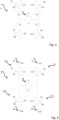
- FIG. 1 A schematic block diagram of an RF plasma generator 1 is shown.
- the generator 1 comprises a voltage supply device 2 in the form of a DC voltage source, by means of which the oscillator circuit 3 is supplied.
- the required high-frequency power is generated by means of the oscillator circuit 3.
- the oscillator circuit 3 is correspondingly connected to the load circuit 4 for generating of the plasma, which has the induction coil L P (not shown separately here) and a capacitance C P connected in parallel to the induction coil.
- the RF plasma generator 1, in particular the voltage supply device 2, further comprises a controllable voltage source 5, which is arranged in a branch of the oscillator circuit 3 and which is designed to adjust a voltage applied to the load circuit 4 and/or at least a potential difference between the induction coil (not shown here) and a spectrometer (likewise not shown), in particular a cone of the spectrometer.
- a controllable voltage source 5 which is arranged in a branch of the oscillator circuit 3 and which is designed to adjust a voltage applied to the load circuit 4 and/or at least a potential difference between the induction coil (not shown here) and a spectrometer (likewise not shown), in particular a cone of the spectrometer.
- Fig. 2 The mode of operation of the controllable voltage source 5 is shown schematically.
- the shape of the plasma P generated in each case, in particular of the plasma core shown here, depends crucially on the potentials U 1 , U 2 between the plasma coil L P and the cone 7, for example a sampler, a spectrometer 6 with which the plasma generator 1 can be used, as well as on the voltage U L applied to the load circuit 4.
- the plasma shape can therefore be specifically influenced.
- dynamic adaptation of the plasma shape during continuous operation is even possible.
- the oscillator circuit 3 comprises a full-bridge circuit of four transistors T1-T4, each of which has a gate electrode E1-E4, via which it can be supplied with a gate control voltage U G .
- the transistors T1-T4 are connected alternately.
- An inductive element L1-L4 is optionally connected in series with each of the transistors T1-T4.
- the inductive elements L1-L4 then each form a series resonant circuit with the output capacitances C1-C4 of the transistors T1-T4.
- Fig. 4 shows an example of a preferred variant of the present invention, in which four controllable voltage sources 5a-5d are used. This can be advantageous, for example, when an oscillator circuit 3 designed as a full-bridge circuit is used.
- the Oscillator circuit 3 is similar to the one in Fig. 3
- Each of the four branches a, b, c, d comprises a transistor T1-T4 and a controllable voltage source 5a-5d for generating the voltages U s aU s d.
- additional series-connected inductors L1-L4 as in the case of Fig. 3 .
- the potentials U 1 , U 2 between the plasma coil L P and the cone 7, as well as the voltage U L applied to the load circuit 4 can be varied.
- This in turn allows the plasma shape, in particular the plasma core, to be specifically influenced, for example, parallel and/or perpendicular to a longitudinal axis I (cf. Fig. 2 ) can be stretched or compressed by the coil L P. All of this can be accomplished without changing the other components used or the coil geometry.
- the distance of the plasma core from the cone 7 of the spectrometer 6 can be adjusted accordingly. Overall, the focusing of the resulting ion beam can thus be precisely controlled using the voltage sources 5a-5d.
- controllable voltage sources 5 may also be provided. It is advantageous, but by no means absolutely necessary, if the number of branches of the oscillator circuit 3 corresponds to the number of controllable voltage sources 5 used.
Landscapes
- Physics & Mathematics (AREA)
- Engineering & Computer Science (AREA)
- Plasma & Fusion (AREA)
- Chemical & Material Sciences (AREA)
- Analytical Chemistry (AREA)
- Spectroscopy & Molecular Physics (AREA)
- Health & Medical Sciences (AREA)
- Electromagnetism (AREA)
- Biochemistry (AREA)
- Life Sciences & Earth Sciences (AREA)
- Nuclear Medicine, Radiotherapy & Molecular Imaging (AREA)
- General Health & Medical Sciences (AREA)
- General Physics & Mathematics (AREA)
- Immunology (AREA)
- Pathology (AREA)
- Power Engineering (AREA)
- Other Investigation Or Analysis Of Materials By Electrical Means (AREA)
- Electron Tubes For Measurement (AREA)
- Investigating, Analyzing Materials By Fluorescence Or Luminescence (AREA)
- Plasma Technology (AREA)
Description
- Die vorliegende Erfindung betrifft einen HF-Plasmagenerator zur Erzeugung eines induktiv gekoppelten Plasmas in der Spektrometrie mit den Merkmalen des Oberbegriffs des ersten Anspruchs und ein Spektrometer mit einem erfindungsgemäßen HF-Plasmagenerator.
- Induktiv gekoppelte Plasmen finden im Bereich der Spektroskopie vielfach Anwendung, beispielsweise zur Erzeugung von Ionen in der Massenspektroskopie oder zur Erzeugung eines Spektrums in der optischen Emissionsspektroskopie.
- Aus dem Stand der Technik sind unterschiedlichste HF-Plasmageneratoren zur Erzeugung eines induktiv gekoppelten Plasmas bekannt geworden, wie beispielsweise freilaufende oder frequenzstabilisierte Generatoren, sowie Generatoren, welche auf Hochleistungsröhren basieren und solche, die Halbleiter verwenden. Grundsätzlich umfasst ein Plasmagenerator typischerweise eine Spannungsversorgungseinrichtung und eine Oszillatorschaltung, welche mit einer Lastschaltung zur Erzeugung des Plasmas gekoppelt ist. Bei den Oszillatorschaltungen handelt es sich beispielsweise um Schaltungen nach Colpitts, Meißner oder Huth-Kühn. Aber auch die Verwendung von Halbrücken- oder Vollbrückenschaltungen sind bekannt geworden. So ist aus der
WO2007/134363A1 ein auf dem Prinzip einer Vollbrückenschaltung basierender HF-Generator für die Spektroskopie bekannt geworden, bei welchem Halbleiter-Schaltelemente zum Einsatz kommen. - Eine Einrichtung zur Erzeugung eines induktiv gekoppelten Plasmas umfasst ferner eine oder mehrere Induktionsspulen, welche koaxial zu einem Brenner angeordnet sind, in welchen ein Gas, häufig Argon-Gas, eingeleitet und dort erhitzt wird. Mittels eines Hochfrequenzgenerators (HF-Generator) wird in den Spulen ein starkes elektromagnetisches Wechselfeld erzeugt, welches das Plasma durch induktive Kopplung mit der benötigten Energie versorgt. Typische Temperaturen des Plasmas liegen im Bereich von 3000 K bis 10000 K. Frequenzen zur Erzeugung der magnetischen Wechselfelder wiederum liegen im Bereich von MHz bis GHz, häufig im Bereich zwischen 10 MHz und 50 MHz. Grundsätzlich müssen die HF-Plasmageneratoren dazu in der Lage sein, ausreichend Leistung zur Erzeugung und Aufrechterhaltung des Plasmas zur Verfügung zu stellen. So liegt die Leistung typischerweise im Bereich von 500 W bis 3 kW. Außerdem sind ein hoher Wirkungsgrad bzw. eine hohe Güte wünschenswert.
- Die
US 2013/265810 A1 offenbart eine Hochfrequenz-Energieversorgungsvorrichtung zur Versorgung einer Last, deren Impedanz stark schwankt, mit Hochfrequenz-Energie, wobei ein stabiler Hochfrequenzstrom aufrechterhalten wird, ohne dass ein Überstrom oder eine Überspannung in einer Treiberschaltung erzeugt wird. Eine ähnliche Vorrichtung lässt sich derUS 2016/066405 A1 oder derWO 2007/134363 A1 entnehmen. Einen Hochfrequenzgenerator, der eine Einstellung einer Plasmaschwingfrequenz vorsieht, offenbart dieEP 2 020 672 A2 . - Ebenfalls von großer Wichtigkeit ist die Plasmaform, welche unter anderem von den jeweils vorherrschenden Potentialen in der Nähe des Plasmas, beispielsweise eines Konus des jeweiligen Spektrometers, von der Form und mechanischen Ausgestaltung der verwendeten Induktionsspule, und verschiedensten Eigenschaften der verwendeten Bauteile abhängt. Um die Form des Plasmas, insbesondere des Plasmakerns, gezielt zu beeinflussen, gilt es beispielsweise, vorherrschende elektrische Potentialverschiebungen in ein analytisches Optimum zu bringen. In diesem Zusammenhang wurden zwar unterschiedliche Schaltungskonzepte beschrieben, die zwar Bedingungen für eine analytisch optimale Ausformung des Plasmas umsetzen, die jedoch in der Regel statisch sind und sich nicht automatisch auf veränderliche Verhältnisse einstellen lassen. So ist typischerweise auch eine aufwändige Anpassung der verwendeten Bauteile sowie der Geometrie der Plasmaspule notwendig, um eine optimale Plasmaformung zu erreichen. Entsprechend stellt jeder Plasmagenerator ein Unikat dar, dessen Fertigungsprozess aufwendig und teuer ist. Eine Serienfertigung von Plasmageneratoren, die die Erzeugung eines analytisch optimal ausgeformten Plasmas ermöglichen, ist dagegen nur sehr schwer realisierbar.
- Hiervon ausgehend liegt der vorliegenden Erfindung die Aufgabe zugrunde, eine Plasmagenerator bereitzustellen, mit welchem sich auf einfache Art und Weise ein optimal ausgeformtes Plasma erzeugen lässt.
- Diese Aufgabe wird gelöst durch den HF-Plasmagenerator mit den Merkmalen des ersten Anspruchs .
- Zudem kann der Plasmagenerator in einer möglichen Ausgestaltung eine Recheneinheit zur Steuerung der steuerbaren Spannungsquelle umfassen.
- Die Bereitstellung einer steuerbaren Spannungsquelle erlaubt eine Formung des Plasmas, insbesondere des Plasmakerns, im fortlaufenden Betrieb des HF-Plasmagenerators. Durch eine gezielte Variation der an der Lastschaltung anliegenden Spannung und/oder zumindest einer Potentialdifferenz zwischen der Induktionsspule und einem Konus eines Spektrometers kann das Plasma, insbesondere der Plasmakern gezielt gestaucht oder gestreckt werden, oder auch eine Entfernung zu einem Konus des Spektrometers verändert werden. Auf diese Weise kann demnach die Plasmaform fortlaufend optimiert und beispielsweise hinsichtlich des analytischen Optimums korrigiert werden. Dies ermöglicht eine steuerbare Bündelung des jeweils erzeugten Ionenstrahls.
- Es ist ein Vorteil der vorliegenden Erfindung, dass eine Verformung des Plasmas mit einem erfindungsgemäßen Plasmagenerator ohne bauteiltechnische Eingriffe in den Generator möglich ist. Durch diese elektronische Justiermöglichkeit können Kosten und Dauer der Fertigung des jeweiligen Generators deutlich reduziert werden, sowie die analytische Leistung des jeweiligen Geräts im fortlaufenden Betrieb optimiert werden.
- In einer Ausgestaltung umfasst die Oszillatorschaltung des HF-Plasmagenerators eine Brückenschaltung, insbesondere eine Halbrückenschaltung oder eine Vollbrückenschaltung.
- In dieser Hinsicht ist es von Vorteil, wenn es sich bei der Brückenschaltung um eine Vollbrückenschaltung mit vier Transistoren, welche in vier Zweigen angeordnet sind, handelt, wobei jeder der Transistoren eine Gate-Elektrode aufweist, über welche er mit einer Gate-Steuerspannung beaufschlagbar ist, und wobei die Transistoren alternierend geschaltet werden, um die HF-Leistung zu erzeugen.
- Es ist ferner von Vorteil, wenn der HF-Plasmagenerator eine Gate-Steuerschaltung zum Erzeugen der Gate-Steuerspannung zum Schalten der Transistoren umfasst.
- Schließlich ist es hinsichtlich der Gate-Steuerschaltung von Vorteil, wenn diese dazu ausgestaltet ist, einen vorgebbaren Wert einer Plasma-Schwingfrequenz eines Lastenschwingkreises einzustellen. Bevorzugt kann die Gate-Steuerschaltung die Plasma-Schwingfrequenz anhand des zeitlichen Verlaufs der Gate-Steuerspannung einstellen, beispielsweise kann es sich bei der Gate-Steuerspannung um ein zeitlich periodisches Signal, insbesondere um ein Rechtecksignal, handeln, mittels welchem die Transistoren auf geeignete Art und Weise ein- und ausgeschaltet werden können. Eine derartige gezielte Steuerung der Gate-Steuerspannung erlaubt vorteilhaft sowohl eine Kompensation variierender Plasmalasten als auch die Kompensation von spezifischen Bauteileigenschaften. Es kann also mittels des erfindungsgemäßen HF-Plasmagenerators auf einfache Weise ein zuverlässiges, analytisch verwertbares Plasma bereitgestellt werden. In diesem Zusammenhang sei auf die deutsche Patentanmeldung mit dem Aktenzeichen
DE 10 2020 106 692.9 verwiesen. - In einer erfindungsgemäßen Variante umfasst der HF-Plasmagenerator zumindest zwei steuerbare Spannungsquellen, welche in zwei unterschiedlichen Zweigen der Oszillatorschaltung angeordnet sind.
- In der anderen erfindungsgemäßen Variante umfasst der HF-Plasmagenerators zumindest vier steuerbare Spannungsquellen, welche in vier unterschiedlichen Zweigen der Oszillatorschaltung angeordnet sind. Diese Variante ist besonders vorteilhaft in Zusammenhang mit einer in Form einer Vollbrückenschaltung ausgestalteten Oszillatorschaltung. In diesem Falle ergibt sich eine gezielte Einstellmöglichkeit der Potentiale in allen vier Quadranten.
- Die Verwendung mehrerer, insbesondere baugleicher, steuerbarer Spannungsquellen erlaubt eine gezielte Einstellung der an der Lastschaltung anliegenden Spannung und/oder zumindest einer Potentialdifferenz zwischen der Induktionsspule und einem Konus des Spektrometers.
- Die der Erfindung zugrundeliegende Aufgabe wird ferner gelöst durch ein Spektrometer umfassend einen erfindungsgemäßen HF-Plasmagenerator nach zumindest einer der beschriebenen Ausgestaltungen.
- Es ist dabei von Vorteil, wenn es sich bei dem Spektrometer um ein Massenspektrometer oder um ein optisches Emissionsspektrometer handelt.
- Es sei darauf verwiesen, dass sich die in Zusammenhang mit dem erfindungsgemäßen HF-Plasmagenerator beschriebenen Ausgestaltungen mutatis mutandis auch auf das erfindungsgemäße Spektrometer anwenden lassen und umgekehrt.
- Nähere Einzelheiten der Erfindung werden anhand der nachfolgenden Figuren erläutert. Es zeigt:
- Fig. 1
- eine schematische Darstellung eines HF-Plasmagenerators mit einer steuerbaren Spannungsquelle,
- Fig. 2
- eine schematische Illustration zur Wirkweise der steuerbaren Spannungsquelle,
- Fig. 3
- ein Schaltbild einer erfindungsgemäßen Oszillatorschaltung in Form einer Vollbrückenschaltung mit vier Transistoren und zusätzlichen induktiven Elementen, und
- Fig. 4
- ein Schaltbild einer erfindungsgemäßen Oszillatorschaltung gemäß
Fig. 3 sowie mit vier steuerbaren Spannungsquellen. - Gleiche Elemente werden in den Figuren mit demselben Bezugszeichen versehen.
- In
Fig. 1 ist ein schematisches Blockschaltbild eines HF-Plasmagenerators 1 gezeigt. Der Generator 1 umfasst eine Spannungsversorgungseinrichtung 2 in Form einer Gleichspannungsquelle, mittels welcher die Oszillatorschaltung 3 versorgt wird. Mittels der Oszillatorschaltung 3 wird die benötigte Hochfrequenzleistung erzeugt. Die Oszillatorschaltung 3 ist entsprechend mit der Lastschaltung 4 zum Erzeugen des Plasmas gekoppelt, welche die hier nicht separat gezeigte Induktionsspule LP und eine zur Induktionsspule parallel geschaltete Kapazität CP aufweist. - Der HF-Plasmagenerator 1, insbesondere die Spannungsversorgungseinrichtung 2, umfasst ferner eine steuerbare Spannungsquelle 5, welche in einem Zweig der Oszillatorschaltung 3 angeordnet ist, und welche dazu ausgestaltet ist, eine an der Lastschaltung 4 anliegende Spannung und/oder zumindest eine Potentialdifferenz zwischen der hier nicht gezeigten Induktionsspule und einem ebenfalls nicht dargestellten Spektrometer, insbesondere einem Konus des Spektrometers, einzustellen.
- In
Fig. 2 ist die Wirkungsweise der steuerbaren Spannungsquelle 5 schematisch dargestellt. Die Form des jeweils erzeugten Plasmas P, insbesondere des hier dargestellten Plasmakerns, hängt unter anderem entscheidend von den Potentialen U1, U2 zwischen der Plasmaspule LP und dem Konus 7, beispielsweise einem Sampler, eines Spektrometers 6, mit welchem der Plasma-Generator 1 verwendbar ist, sowie von der an der Lastschaltung 4 anliegenden Spannung UL, ab. Durch eine gezielte Einstellung einer oder mehrerer dieser Potentiale lässt sich demnach die Plasmaform gezielt beeinflussen. Insbesondere ist sogar eine dynamische Anpassung der Plasmaform im fortlaufenden Betrieb möglich. - Eine exemplarische Ausgestaltung für eine Oszillatorschaltung 3 ist in
Fig. 3 dargestellt. Die Oszillatorschaltung 3 umfasst eine Vollbrückenschaltung aus vier Transistoren T1-T4, wobei jeder der Transistoren eine Gate-Elektrode E1-E4 aufweist, über welche er mit einer Gate-Steuerspannung UG beaufschlagbar ist. Zum Erzeugen der HF-Leistung für den Lastkreis 4 mit der Induktionsspule LP und der Kapazität CP werden die Transistoren T1-T4 alternierend geschaltet. Zu jedem der Transistoren T1-T4 ist optional ein induktives Element L1-L4 in Reihe geschaltet. Die induktiven Elemente L1-L4 bilden dann mit den Ausgangskapazitäten C1-C4 der Transistoren T1-T4 jeweils einen Reihenschwingkreis aus. -
Fig. 4 zeigt beispielhaft eine bevorzugte Variante der vorliegenden Erfindung, bei welcher vier steuerbare Spannungsquellen 5a-5d verwenden. Dies kann beispielsweise dann von Vorteil sein, wenn eine als Vollbrückenschaltung ausgestalte Oszillatorschaltung 3 zum Einsatz kommt. Die hier gezeigte Oszillatorschaltung 3 ist ähnlich wie die inFig. 3 gezeigte ausgebildet. Jeder der vier Zweige a,b,c,d umfasst einen Transistor T1-T4 sowie eine steuerbare Spannungsquelle 5a-5d zur Erzeugung, mittels welcher die Spannungen Usa-Usd erzeugbar sind. Optional wäre es auch für den Fall derFig. 4 denkbar, zusätzliche, in Reihe geschaltete Induktivitäten L1-L4 zu verwenden, wie im Falle derFig. 3 . - Mittels der gesteuerten Spannungsquellen 5a-5d bzw. mittels der Spannungen Usa-Usd können die Potentiale U1, U2 zwischen der Plasmaspule LP und dem Konus 7, sowie die an der Lastschaltung 4 anliegenden Spannung UL variiert werden. Dadurch wiederum kann die Plasmaform, insb. der Plasmakern gezielt beeinflusst, beispielsweise parallel und/oder senkrecht zu einer Längsachse I (vgl.
Fig. 2 ) durch die Spule LP gestreckt oder gestaucht, werden. Dies alles kann ohne eine Veränderung der weiteren verwendeten Bauteile und ohne eine Änderung der Spulengeometrie erfolgen. Zudem kann eine Entfernung des Plasmakerns zum Konus 7 des Spektrometers 6 passend eingestellt werden. Insgesamt ist somit auch die Bündelung des entstehenden Ionenstrahls anhand der Spannungsquellen 5a-5d gezielt steuerbar. - In anderen Ausgestaltungen können auch andere Anzahlen von steuerbaren Spannungsquellen 5 vorgesehen sein. Es ist vorteilhaft, jedoch keineswegs zwingend notwendig, wenn die Anzahl an Zweigen der Oszillatorschaltung 3 der Anzahl der verwendeten steuerbaren Spannungsquellen 5 entspricht.
-
- 1
- HF-Plasmagenerator
- 2
- Spannungsversorgungseinrichtung
- 3
- Oszillatorschaltung
- 4
- Lastschaltung
- 5,5a-5d
- Steuerbare Spannungsquelle
- 6
- Spektrometer
- 7
- Konus
- T1-T4
- Transistoren
- E1-E4
- Gate-Elektroden
- LP
- Induktionsspule
- CP
- Kapazität
- L1-L4
- Induktive Elemente
- C1-C4
- Ausgangskapazitäten
- Usa-Usd
- Spannungen der steuerbaren Spannungsquellen
- U1, U2
- Potentiale zwischen Induktionsspule und Konus
- P
- Plasma, Plasmakern
- L
- Längsachse
Claims (6)
- HF-Plasmagenerator (1) zur Erzeugung eines induktiv gekoppelten Plasmas (P) in der Spektrometrie, umfassendeine Spannungsversorgungseinrichtung (2) mit einer Gleichspannungsquelle, eine an die Spannungsversorgungseinrichtung (2) angeschlossene Oszillatorschaltung (3) zum Erzeugen von HF-Leistung, undeine mit der Oszillatorschaltung (3) gekoppelte Lastschaltung (4) zum Erzeugen des Plasmas (P), welche Lastschaltung (4) zumindest eine Induktionsspule (LP) und eine zur Induktionsspule (LP) parallel geschaltete Kapazität (Cp) aufweist,dadurch gekennzeichnet,dass die Spannungsversorgungseinrichtung (2) ferner zwei steuerbare Spannungsquellen (5) oder vier steuerbare Spannungsquellen (5a-5d) umfasst, welche in zwei unterschiedlichen Zweigen bzw. vier unterschiedlichen Zweigen (a-d) der Oszillatorschaltung (3) angeordnet sind, unddass die steuerbare Spannungsquellen (5, 5a-5d) dazu ausgestaltet sind, eine an der Lastschaltung (4) anliegende Spannung (UL) und/oder zumindest eine Potentialdifferenz (U1,U2) zwischen der Induktionsspule (LP) und einem Spektrometer (6) einzustellen.
- HF-Plasmagenerator (1) nach Anspruch 1,wobei die Oszillatorschaltung (3) eine Brückenschaltung umfasst,wobei es sich bei der Brückenschaltung um eine Vollbrückenschaltung mit vier Transistoren (T1-T4), welche in vier Zweigen (a-d) der Oszillatorschaltung (3) angeordnet sind, handelt,wobei jeder der Transistoren (T1-T4) eine Gate-Elektrode (E1-E4) aufweist, über welche der Transistor (T1-T4) mit einer Gate-Steuerspannung beaufschlagbar ist, undwobei die Transistoren (T1-T4) alternierend geschaltet werden, um die HF-Leistung zu erzeugen.
- HF-Plasmagenerator (1) nach Anspruch 2,
umfassend eine Gate-Steuerschaltung zum Erzeugen der Gate-Steuerspannung zum Schalten der Transistoren (T1-T4). - HF-Plasmagenerator (1) nach Anspruch 3,
wobei die Gate-Steuerschaltung dazu ausgestaltet ist, einen vorgebbaren Wert einer Plasma-Schwingfrequenz eines Lastenschwingkreises einzustellen. - Spektrometer (6) umfassend einen HF-Plasmagenerator (1) nach zumindest einem der Ansprüche 1 bis 4.
- Spektrometer (6) nach Anspruch 5,
wobei es sich bei dem Spektrometer (6) um ein Massenspektrometer oder um ein optisches Emissionsspektrometer handelt.
Applications Claiming Priority (1)
| Application Number | Priority Date | Filing Date | Title |
|---|---|---|---|
| DE102020117402.0A DE102020117402A1 (de) | 2020-07-01 | 2020-07-01 | Generator für die Spektrometrie |
Publications (2)
| Publication Number | Publication Date |
|---|---|
| EP3933884A1 EP3933884A1 (de) | 2022-01-05 |
| EP3933884B1 true EP3933884B1 (de) | 2025-05-14 |
Family
ID=76522870
Family Applications (1)
| Application Number | Title | Priority Date | Filing Date |
|---|---|---|---|
| EP21180224.4A Active EP3933884B1 (de) | 2020-07-01 | 2021-06-18 | Generator für die spektrometrie |
Country Status (4)
| Country | Link |
|---|---|
| US (1) | US12022603B2 (de) |
| EP (1) | EP3933884B1 (de) |
| CN (1) | CN113889396B (de) |
| DE (1) | DE102020117402A1 (de) |
Families Citing this family (1)
| Publication number | Priority date | Publication date | Assignee | Title |
|---|---|---|---|---|
| EP4036793A1 (de) * | 2021-02-01 | 2022-08-03 | Centre national de la recherche scientifique | Verfahren zur erkennung eines musters in einem bild und zugehörige vorrichtungen |
Family Cites Families (17)
| Publication number | Priority date | Publication date | Assignee | Title |
|---|---|---|---|---|
| AU2003203127A1 (en) * | 2002-03-15 | 2003-09-29 | Unaxis Balzers Ag | Vacuum plasma generator |
| CN1314191C (zh) * | 2002-12-03 | 2007-05-02 | 夏义峰 | 带有功率控制的电感耦合等离子体自激式射频发生器 |
| US7214934B2 (en) | 2004-07-22 | 2007-05-08 | Varian Australia Pty Ltd | Radio frequency power generator |
| WO2007134363A1 (en) | 2006-05-22 | 2007-11-29 | Varian Australia Pty Ltd | Power generator for spectrometry |
| DE102007036592B4 (de) * | 2007-08-02 | 2014-07-10 | Astrium Gmbh | Hochfrequenzgenerator für Ionen- und Elektronenquellen |
| US8610501B2 (en) * | 2009-11-16 | 2013-12-17 | Covidien Lp | Class resonant-H electrosurgical generators |
| WO2012039035A1 (ja) | 2010-09-22 | 2012-03-29 | 株式会社 島津製作所 | 高周波電源 |
| JP5729693B2 (ja) * | 2011-03-30 | 2015-06-03 | 株式会社ダイヘン | 高周波電源装置 |
| CN102891613A (zh) * | 2011-07-21 | 2013-01-23 | 台达电子企业管理(上海)有限公司 | 一种ac-dc 电源转换器及其dc 充电站 |
| US9028479B2 (en) * | 2011-08-01 | 2015-05-12 | Covidien Lp | Electrosurgical apparatus with real-time RF tissue energy control |
| US9283028B2 (en) * | 2013-03-15 | 2016-03-15 | Covidien Lp | Crest-factor control of phase-shifted inverter |
| US9872719B2 (en) * | 2013-07-24 | 2018-01-23 | Covidien Lp | Systems and methods for generating electrosurgical energy using a multistage power converter |
| JP2016054041A (ja) * | 2014-09-03 | 2016-04-14 | 株式会社島津製作所 | 高周波電源装置 |
| US20160066504A1 (en) | 2014-09-05 | 2016-03-10 | Michael Holman | Crop Stubble Flattening and Slicing Apparatus |
| KR102746117B1 (ko) * | 2016-01-22 | 2024-12-24 | 에스피피 테크놀로지스 컴퍼니 리미티드 | 플라즈마 제어 장치 |
| JP2022544983A (ja) * | 2019-08-19 | 2022-10-24 | シグニファイ ホールディング ビー ヴィ | Dc供給電圧を複数の平衡dc出力電圧に変換するためのスイッチング電力変換器 |
| DE102020106692A1 (de) | 2020-03-11 | 2021-09-16 | Analytik Jena Gmbh | Generator für die Spektrometrie |
-
2020
- 2020-07-01 DE DE102020117402.0A patent/DE102020117402A1/de active Pending
-
2021
- 2021-06-18 EP EP21180224.4A patent/EP3933884B1/de active Active
- 2021-06-28 CN CN202110718867.0A patent/CN113889396B/zh active Active
- 2021-06-29 US US17/362,041 patent/US12022603B2/en active Active
Also Published As
| Publication number | Publication date |
|---|---|
| US20220007490A1 (en) | 2022-01-06 |
| US12022603B2 (en) | 2024-06-25 |
| CN113889396B (zh) | 2025-03-07 |
| EP3933884A1 (de) | 2022-01-05 |
| CN113889396A (zh) | 2022-01-04 |
| DE102020117402A1 (de) | 2022-01-05 |
Similar Documents
| Publication | Publication Date | Title |
|---|---|---|
| DE102018204587B4 (de) | Verfahren zur Zündung eines Plasmas in einer Plasmakammer und Zündschaltung | |
| EP2097921B1 (de) | Hochfrequenzstromversorgungsanordnung, insbesondere eine plasmaversorgungseinrichtung und verfahren zum betreiben einer hochfrequenzstromversorgungseinrichtung | |
| DE102018121942B3 (de) | Ionenfalle, Verfahren zum Regeln der Ionenfalle und Verwendungen als Antrieb einer Ionenfalle | |
| DE69914435T2 (de) | Abstimmbare und anpassbare Resonator-Spulenanordnung für Ionenimplantation-Linearbeschleuniger | |
| DE19933842A1 (de) | Vorrichtung und Verfahren zum Ätzen eines Substrates mittels eines induktiv gekoppelten Plasmas | |
| EP3894794B1 (de) | Vorrichtung zur anregung eines resolvers und resolveranordnung | |
| DE112013005486T5 (de) | HF-Transformator | |
| EP2020672A2 (de) | Hochfrequenzgenerator für Ionen- und Elektronenquellen | |
| EP3933884A1 (de) | Generator für die spektrometrie | |
| DE102006005128B4 (de) | Verfahren und Vorrichtung zur Lastanpassung | |
| DE3884790T2 (de) | Durch hf-entladung angeregter laser. | |
| DE102020106692A1 (de) | Generator für die Spektrometrie | |
| DE4322608C2 (de) | Einrichtung zur Leistungsmodulation bei einer Plasmaanregung, vorzugsweise beim Einsatz von Gaslasern | |
| DE102005049583A1 (de) | Elektronisches Vorschaltgerät und Verfahren zum Betreiben einer elektrischen Lampe | |
| EP0957529A1 (de) | Verfahren zum Abgleichen der Resonanzfrequenz eines Ringresonators | |
| EP1634484B1 (de) | Ansteuerung für einen excimer-strahler | |
| DE10304544A1 (de) | Elektronisches Vorschaltgerät | |
| DE4404077C2 (de) | Anordnung und Verfahren zum plasmagestützten Bearbeiten von Werkstücken | |
| EP4091189A1 (de) | Resonator und leistungsoszillator zum aufbau einer integrierten plasmaquelle sowie deren verwendung | |
| DE4440130A1 (de) | Anordnung und Verfahren zum Zünden bzw. Löschen von Gasentladungen, insbesondere bei Gaslasern | |
| DE102024104008A1 (de) | HF-Generator für ein Plasmabearbeitungssystem und ein solches Plasmabearbeitungssystem | |
| DE298484C (de) | ||
| DE102023115520A1 (de) | Hochleistungslasersystem mit vereinfachter impedanzanpassung | |
| EP3005551A1 (de) | Hochfrequenz-oszillator, hochfrequenz-schweissanlage und verfahren zur frequenzregelung mit einem derartigen hochfrequenz-oszillator | |
| WO2004054327A1 (de) | Elektrische schaltung zum zünden einer entladungslampe und verfahren zum zünden der entladungslampe |
Legal Events
| Date | Code | Title | Description |
|---|---|---|---|
| PUAI | Public reference made under article 153(3) epc to a published international application that has entered the european phase |
Free format text: ORIGINAL CODE: 0009012 |
|
| STAA | Information on the status of an ep patent application or granted ep patent |
Free format text: STATUS: THE APPLICATION HAS BEEN PUBLISHED |
|
| STAA | Information on the status of an ep patent application or granted ep patent |
Free format text: STATUS: REQUEST FOR EXAMINATION WAS MADE |
|
| AK | Designated contracting states |
Kind code of ref document: A1 Designated state(s): AL AT BE BG CH CY CZ DE DK EE ES FI FR GB GR HR HU IE IS IT LI LT LU LV MC MK MT NL NO PL PT RO RS SE SI SK SM TR |
|
| B565 | Issuance of search results under rule 164(2) epc |
Effective date: 20211129 |
|
| 17P | Request for examination filed |
Effective date: 20211209 |
|
| RBV | Designated contracting states (corrected) |
Designated state(s): AL AT BE BG CH CY CZ DE DK EE ES FI FR GB GR HR HU IE IS IT LI LT LU LV MC MK MT NL NO PL PT RO RS SE SI SK SM TR |
|
| RAP3 | Party data changed (applicant data changed or rights of an application transferred) |
Owner name: ANALYTIK JENA GMBH+CO. KG |
|
| STAA | Information on the status of an ep patent application or granted ep patent |
Free format text: STATUS: EXAMINATION IS IN PROGRESS |
|
| 17Q | First examination report despatched |
Effective date: 20241025 |
|
| GRAP | Despatch of communication of intention to grant a patent |
Free format text: ORIGINAL CODE: EPIDOSNIGR1 |
|
| STAA | Information on the status of an ep patent application or granted ep patent |
Free format text: STATUS: GRANT OF PATENT IS INTENDED |
|
| INTG | Intention to grant announced |
Effective date: 20250217 |
|
| GRAS | Grant fee paid |
Free format text: ORIGINAL CODE: EPIDOSNIGR3 |
|
| GRAA | (expected) grant |
Free format text: ORIGINAL CODE: 0009210 |
|
| STAA | Information on the status of an ep patent application or granted ep patent |
Free format text: STATUS: THE PATENT HAS BEEN GRANTED |
|
| AK | Designated contracting states |
Kind code of ref document: B1 Designated state(s): AL AT BE BG CH CY CZ DE DK EE ES FI FR GB GR HR HU IE IS IT LI LT LU LV MC MK MT NL NO PL PT RO RS SE SI SK SM TR |
|
| REG | Reference to a national code |
Ref country code: GB Ref legal event code: FG4D Free format text: NOT ENGLISH |
|
| REG | Reference to a national code |
Ref country code: CH Ref legal event code: EP |
|
| REG | Reference to a national code |
Ref country code: IE Ref legal event code: FG4D Free format text: LANGUAGE OF EP DOCUMENT: GERMAN |
|
| REG | Reference to a national code |
Ref country code: DE Ref legal event code: R096 Ref document number: 502021007451 Country of ref document: DE |
|
| P01 | Opt-out of the competence of the unified patent court (upc) registered |
Free format text: CASE NUMBER: APP_28531/2025 Effective date: 20250616 |
|
| PGFP | Annual fee paid to national office [announced via postgrant information from national office to epo] |
Ref country code: AT Payment date: 20250721 Year of fee payment: 5 |
|
| REG | Reference to a national code |
Ref country code: NL Ref legal event code: MP Effective date: 20250514 |
|
| PG25 | Lapsed in a contracting state [announced via postgrant information from national office to epo] |
Ref country code: FI Free format text: LAPSE BECAUSE OF FAILURE TO SUBMIT A TRANSLATION OF THE DESCRIPTION OR TO PAY THE FEE WITHIN THE PRESCRIBED TIME-LIMIT Effective date: 20250514 Ref country code: ES Free format text: LAPSE BECAUSE OF FAILURE TO SUBMIT A TRANSLATION OF THE DESCRIPTION OR TO PAY THE FEE WITHIN THE PRESCRIBED TIME-LIMIT Effective date: 20250514 Ref country code: PT Free format text: LAPSE BECAUSE OF FAILURE TO SUBMIT A TRANSLATION OF THE DESCRIPTION OR TO PAY THE FEE WITHIN THE PRESCRIBED TIME-LIMIT Effective date: 20250915 |
|
| PGFP | Annual fee paid to national office [announced via postgrant information from national office to epo] |
Ref country code: DE Payment date: 20250627 Year of fee payment: 5 |
|
| REG | Reference to a national code |
Ref country code: LT Ref legal event code: MG9D |
|
| PG25 | Lapsed in a contracting state [announced via postgrant information from national office to epo] |
Ref country code: NO Free format text: LAPSE BECAUSE OF FAILURE TO SUBMIT A TRANSLATION OF THE DESCRIPTION OR TO PAY THE FEE WITHIN THE PRESCRIBED TIME-LIMIT Effective date: 20250814 Ref country code: GR Free format text: LAPSE BECAUSE OF FAILURE TO SUBMIT A TRANSLATION OF THE DESCRIPTION OR TO PAY THE FEE WITHIN THE PRESCRIBED TIME-LIMIT Effective date: 20250815 |
|
| PG25 | Lapsed in a contracting state [announced via postgrant information from national office to epo] |
Ref country code: PL Free format text: LAPSE BECAUSE OF FAILURE TO SUBMIT A TRANSLATION OF THE DESCRIPTION OR TO PAY THE FEE WITHIN THE PRESCRIBED TIME-LIMIT Effective date: 20250514 Ref country code: NL Free format text: LAPSE BECAUSE OF FAILURE TO SUBMIT A TRANSLATION OF THE DESCRIPTION OR TO PAY THE FEE WITHIN THE PRESCRIBED TIME-LIMIT Effective date: 20250514 |
|
| PG25 | Lapsed in a contracting state [announced via postgrant information from national office to epo] |
Ref country code: BG Free format text: LAPSE BECAUSE OF FAILURE TO SUBMIT A TRANSLATION OF THE DESCRIPTION OR TO PAY THE FEE WITHIN THE PRESCRIBED TIME-LIMIT Effective date: 20250514 |
|
| PG25 | Lapsed in a contracting state [announced via postgrant information from national office to epo] |
Ref country code: HR Free format text: LAPSE BECAUSE OF FAILURE TO SUBMIT A TRANSLATION OF THE DESCRIPTION OR TO PAY THE FEE WITHIN THE PRESCRIBED TIME-LIMIT Effective date: 20250514 |
|
| PG25 | Lapsed in a contracting state [announced via postgrant information from national office to epo] |
Ref country code: RS Free format text: LAPSE BECAUSE OF FAILURE TO SUBMIT A TRANSLATION OF THE DESCRIPTION OR TO PAY THE FEE WITHIN THE PRESCRIBED TIME-LIMIT Effective date: 20250814 |
|
| PG25 | Lapsed in a contracting state [announced via postgrant information from national office to epo] |
Ref country code: IS Free format text: LAPSE BECAUSE OF FAILURE TO SUBMIT A TRANSLATION OF THE DESCRIPTION OR TO PAY THE FEE WITHIN THE PRESCRIBED TIME-LIMIT Effective date: 20250914 |
|
| PG25 | Lapsed in a contracting state [announced via postgrant information from national office to epo] |
Ref country code: LV Free format text: LAPSE BECAUSE OF FAILURE TO SUBMIT A TRANSLATION OF THE DESCRIPTION OR TO PAY THE FEE WITHIN THE PRESCRIBED TIME-LIMIT Effective date: 20250514 |
|
| PG25 | Lapsed in a contracting state [announced via postgrant information from national office to epo] |
Ref country code: DK Free format text: LAPSE BECAUSE OF FAILURE TO SUBMIT A TRANSLATION OF THE DESCRIPTION OR TO PAY THE FEE WITHIN THE PRESCRIBED TIME-LIMIT Effective date: 20250514 Ref country code: SM Free format text: LAPSE BECAUSE OF FAILURE TO SUBMIT A TRANSLATION OF THE DESCRIPTION OR TO PAY THE FEE WITHIN THE PRESCRIBED TIME-LIMIT Effective date: 20250514 |
|
| PG25 | Lapsed in a contracting state [announced via postgrant information from national office to epo] |
Ref country code: CZ Free format text: LAPSE BECAUSE OF FAILURE TO SUBMIT A TRANSLATION OF THE DESCRIPTION OR TO PAY THE FEE WITHIN THE PRESCRIBED TIME-LIMIT Effective date: 20250514 |
|
| PG25 | Lapsed in a contracting state [announced via postgrant information from national office to epo] |
Ref country code: EE Free format text: LAPSE BECAUSE OF FAILURE TO SUBMIT A TRANSLATION OF THE DESCRIPTION OR TO PAY THE FEE WITHIN THE PRESCRIBED TIME-LIMIT Effective date: 20250514 |
|
| PG25 | Lapsed in a contracting state [announced via postgrant information from national office to epo] |
Ref country code: SK Free format text: LAPSE BECAUSE OF FAILURE TO SUBMIT A TRANSLATION OF THE DESCRIPTION OR TO PAY THE FEE WITHIN THE PRESCRIBED TIME-LIMIT Effective date: 20250514 Ref country code: RO Free format text: LAPSE BECAUSE OF FAILURE TO SUBMIT A TRANSLATION OF THE DESCRIPTION OR TO PAY THE FEE WITHIN THE PRESCRIBED TIME-LIMIT Effective date: 20250514 |
|
| REG | Reference to a national code |
Ref country code: CH Ref legal event code: H13 Free format text: ST27 STATUS EVENT CODE: U-0-0-H10-H13 (AS PROVIDED BY THE NATIONAL OFFICE) Effective date: 20260127 |
|
| PG25 | Lapsed in a contracting state [announced via postgrant information from national office to epo] |
Ref country code: IT Free format text: LAPSE BECAUSE OF FAILURE TO SUBMIT A TRANSLATION OF THE DESCRIPTION OR TO PAY THE FEE WITHIN THE PRESCRIBED TIME-LIMIT Effective date: 20250514 |
|
| PG25 | Lapsed in a contracting state [announced via postgrant information from national office to epo] |
Ref country code: LU Free format text: LAPSE BECAUSE OF NON-PAYMENT OF DUE FEES Effective date: 20250618 |
|
| REG | Reference to a national code |
Ref country code: DE Ref legal event code: R097 Ref document number: 502021007451 Country of ref document: DE |
|
| PG25 | Lapsed in a contracting state [announced via postgrant information from national office to epo] |
Ref country code: MC Free format text: LAPSE BECAUSE OF FAILURE TO SUBMIT A TRANSLATION OF THE DESCRIPTION OR TO PAY THE FEE WITHIN THE PRESCRIBED TIME-LIMIT Effective date: 20250514 |
|
| REG | Reference to a national code |
Ref country code: BE Ref legal event code: MM Effective date: 20250630 |
|
| PLBE | No opposition filed within time limit |
Free format text: ORIGINAL CODE: 0009261 |
|
| STAA | Information on the status of an ep patent application or granted ep patent |
Free format text: STATUS: NO OPPOSITION FILED WITHIN TIME LIMIT |
|
| REG | Reference to a national code |
Ref country code: CH Ref legal event code: L10 Free format text: ST27 STATUS EVENT CODE: U-0-0-L10-L00 (AS PROVIDED BY THE NATIONAL OFFICE) Effective date: 20260325 |
|
| PG25 | Lapsed in a contracting state [announced via postgrant information from national office to epo] |
Ref country code: IE Free format text: LAPSE BECAUSE OF NON-PAYMENT OF DUE FEES Effective date: 20250618 |
|
| PG25 | Lapsed in a contracting state [announced via postgrant information from national office to epo] |
Ref country code: BE Free format text: LAPSE BECAUSE OF NON-PAYMENT OF DUE FEES Effective date: 20250630 |
|
| PG25 | Lapsed in a contracting state [announced via postgrant information from national office to epo] |
Ref country code: FR Free format text: LAPSE BECAUSE OF NON-PAYMENT OF DUE FEES Effective date: 20250714 |
|
| 26N | No opposition filed |
Effective date: 20260217 |
|
| PG25 | Lapsed in a contracting state [announced via postgrant information from national office to epo] |
Ref country code: CH Free format text: LAPSE BECAUSE OF NON-PAYMENT OF DUE FEES Effective date: 20250630 |
|
| GBPC | Gb: european patent ceased through non-payment of renewal fee |
Effective date: 20250814 |