EP3933869A1 - Betätigungsmechanismus für doppelstromversorgungwechselschalter sowie doppelstromversorgungwechselschalter - Google Patents
Betätigungsmechanismus für doppelstromversorgungwechselschalter sowie doppelstromversorgungwechselschalter Download PDFInfo
- Publication number
- EP3933869A1 EP3933869A1 EP21305856.3A EP21305856A EP3933869A1 EP 3933869 A1 EP3933869 A1 EP 3933869A1 EP 21305856 A EP21305856 A EP 21305856A EP 3933869 A1 EP3933869 A1 EP 3933869A1
- Authority
- EP
- European Patent Office
- Prior art keywords
- supporting plate
- operating mechanism
- disc
- elastic member
- driving
- Prior art date
- Legal status (The legal status is an assumption and is not a legal conclusion. Google has not performed a legal analysis and makes no representation as to the accuracy of the status listed.)
- Granted
Links
Images




Classifications
-
- H—ELECTRICITY
- H01—ELECTRIC ELEMENTS
- H01H—ELECTRIC SWITCHES; RELAYS; SELECTORS; EMERGENCY PROTECTIVE DEVICES
- H01H3/00—Mechanisms for operating contacts
- H01H3/32—Driving mechanisms, i.e. for transmitting driving force to the contacts
- H01H3/40—Driving mechanisms, i.e. for transmitting driving force to the contacts using friction, toothed, or screw-and-nut gearing
-
- H—ELECTRICITY
- H01—ELECTRIC ELEMENTS
- H01H—ELECTRIC SWITCHES; RELAYS; SELECTORS; EMERGENCY PROTECTIVE DEVICES
- H01H3/00—Mechanisms for operating contacts
- H01H3/32—Driving mechanisms, i.e. for transmitting driving force to the contacts
- H01H3/42—Driving mechanisms, i.e. for transmitting driving force to the contacts using cam or eccentric
-
- H—ELECTRICITY
- H01—ELECTRIC ELEMENTS
- H01H—ELECTRIC SWITCHES; RELAYS; SELECTORS; EMERGENCY PROTECTIVE DEVICES
- H01H3/00—Mechanisms for operating contacts
- H01H3/22—Power arrangements internal to the switch for operating the driving mechanism
- H01H3/30—Power arrangements internal to the switch for operating the driving mechanism using spring motor
- H01H2003/3084—Kinetic energy of moving parts recuperated by transformation into potential energy in closing or opening spring to be used in next operation
-
- H—ELECTRICITY
- H01—ELECTRIC ELEMENTS
- H01H—ELECTRIC SWITCHES; RELAYS; SELECTORS; EMERGENCY PROTECTIVE DEVICES
- H01H2300/00—Orthogonal indexing scheme relating to electric switches, relays, selectors or emergency protective devices covered by H01H
- H01H2300/018—Application transfer; between utility and emergency power supply
-
- H—ELECTRICITY
- H01—ELECTRIC ELEMENTS
- H01H—ELECTRIC SWITCHES; RELAYS; SELECTORS; EMERGENCY PROTECTIVE DEVICES
- H01H3/00—Mechanisms for operating contacts
- H01H3/22—Power arrangements internal to the switch for operating the driving mechanism
- H01H3/28—Power arrangements internal to the switch for operating the driving mechanism using electromagnet
-
- Y—GENERAL TAGGING OF NEW TECHNOLOGICAL DEVELOPMENTS; GENERAL TAGGING OF CROSS-SECTIONAL TECHNOLOGIES SPANNING OVER SEVERAL SECTIONS OF THE IPC; TECHNICAL SUBJECTS COVERED BY FORMER USPC CROSS-REFERENCE ART COLLECTIONS [XRACs] AND DIGESTS
- Y02—TECHNOLOGIES OR APPLICATIONS FOR MITIGATION OR ADAPTATION AGAINST CLIMATE CHANGE
- Y02B—CLIMATE CHANGE MITIGATION TECHNOLOGIES RELATED TO BUILDINGS, e.g. HOUSING, HOUSE APPLIANCES OR RELATED END-USER APPLICATIONS
- Y02B70/00—Technologies for an efficient end-user side electric power management and consumption
- Y02B70/30—Systems integrating technologies related to power network operation and communication or information technologies for improving the carbon footprint of the management of residential or tertiary loads, i.e. smart grids as climate change mitigation technology in the buildings sector, including also the last stages of power distribution and the control, monitoring or operating management systems at local level
-
- Y—GENERAL TAGGING OF NEW TECHNOLOGICAL DEVELOPMENTS; GENERAL TAGGING OF CROSS-SECTIONAL TECHNOLOGIES SPANNING OVER SEVERAL SECTIONS OF THE IPC; TECHNICAL SUBJECTS COVERED BY FORMER USPC CROSS-REFERENCE ART COLLECTIONS [XRACs] AND DIGESTS
- Y04—INFORMATION OR COMMUNICATION TECHNOLOGIES HAVING AN IMPACT ON OTHER TECHNOLOGY AREAS
- Y04S—SYSTEMS INTEGRATING TECHNOLOGIES RELATED TO POWER NETWORK OPERATION, COMMUNICATION OR INFORMATION TECHNOLOGIES FOR IMPROVING THE ELECTRICAL POWER GENERATION, TRANSMISSION, DISTRIBUTION, MANAGEMENT OR USAGE, i.e. SMART GRIDS
- Y04S20/00—Management or operation of end-user stationary applications or the last stages of power distribution; Controlling, monitoring or operating thereof
- Y04S20/20—End-user application control systems
Definitions
- the present disclosure relates to an operating mechanism for a dual power supply changeover switch and a dual power supply changeover switch.
- Dual power supply changeover switches are widely used in industrial field, especially in emergency power supply systems. Based on the condition of a power supply circuit, the dual power supply changeover switch can switch a load circuit from one power supply to another one, for example, switching between a commercial power supply and a standby power supply, so as to maintain a continuous and reliable operation of the load circuit.
- the present disclosure provides an operating mechanism for a dual power supply changeover switch and a dual power supply changeover switch.
- Such operating mechanism has a symmetrical configuration, so that it can be flexibly assembled, can meet requirements of different application situations, decreases the types of components and parts, reduces the cost and improves the reliability.
- the present disclosure provides an operating mechanism for a dual power supply changeover switch capable of switching among a dual-off position, a first power-on position and a second power-on position.
- the operating mechanism includes: a first supporting plate and a second supporting plate which are parallel to each other and spaced apart from each other; a plurality of first supporting members configured to fix the first supporting plate and the second supporting plate together; a first electromagnet assembly and a second electromagnet assembly which are symmetrically mounted on the first supporting plate and the second supporting plate about a symmetry plane; and an output assembly mounted on the first supporting plate and the second supporting plate along a rotation axis in the symmetry plane, the output assembly is capable of rotating around the rotation axis and has a first driving rod, the first driving rod protrudes from the second supporting plate and is connected to a movable contact carrier.
- the first electromagnet assembly and the second electromagnet assembly are configured to drive the output assembly to rotate in a first direction and a second direction which are opposite to each other, respectively, and hence to drive the movable contact carrier of the dual power supply changeover switch to rotate by the first driving rod.
- the operating mechanism further includes a first elastic member and a second elastic member which are symmetrically arranged about the symmetry plane, wherein one end of the first elastic member abuts against the output assembly, and the other end of the first elastic member is mounted between the first supporting plate and the second supporting plate through a pivot shaft of the first elastic member, so that it can store an energy when the output assembly rotates and can release the energy after passing through a "dead point" to drive the output assembly to further rotate; one end of the second elastic member abuts against the output assembly, and the other end of the second elastic member is mounted between the first supporting plate and the second supporting plate through a pivot shaft of the second elastic member, so that it can store an energy when the output assembly rotates and can release the energy after passing through a "dead point" to drive the output assembly to further rotate.
- the second supporting plate is provided with an opening for the first driving rod.
- the operating mechanism further includes: a third supporting plate which is parallel to the first supporting plate and the second supporting plate and is located between the first supporting plate and the second supporting plate; a second supporting member configured to fix the first supporting plate and the third supporting plate together; and a third supporting member configured to fix the second supporting plate and the third supporting plate together, wherein the other end of the first elastic member and the other end of the second elastic member are mounted between the first supporting plate and the third supporting plate through corresponding pivot shafts.
- the first supporting plate and the third supporting plate are provided with a plurality of first holes, the plurality of first holes are configured to mount the pivot shaft of the first elastic member and the pivot shaft of the second elastic member and are arranged symmetrically with respect to the symmetry plane.
- the output assembly includes: a rotating shaft mounted on the first supporting plate and the second supporting plate along a rotation axis; a rotating disc mounted on the rotating shaft and capable of rotating around the rotating shaft; and a first driving disc mounted on the rotating shaft and capable of rotating in cooperation with the rotating disc when the rotating disc rotates, wherein the first driving rod is fixed on the first driving disc.
- the output assembly further includes a transmission disc, the transmission disc is mounted on the rotating shaft and is capable of driving the first driving disc to rotate when the rotating disc rotates, and the transmission disc includes tooth parts symmetrical about the symmetry plane.
- the operating mechanism further includes a manual operating member mounted between the second supporting plate and the third supporting plate at one side of the symmetry plane, and tooth parts of the manual operating member are engaged with the tooth parts of the transmission disc to rotate the transmission disc under a manual operation so as to drive the first driving disc to rotate.
- the manual operating member has a mounting shaft; and the second supporting plate and the third supporting plate are provided with a plurality of second holes for the mounting shaft, and the plurality of second holes are arranged symmetrically with respect to the symmetry plane.
- the operating mechanism further includes a second driving disc and a second driving rod, wherein the second driving disc is mounted on the rotating shaft, is located near the first supporting plate, and is capable of rotating together with the first driving disc; and the second driving rod is fixed on the second driving disc, protrudes out of the operating mechanism from a side opposite to the first driving rod, and is connected to another movable contact carrier so as to drive the another movable contact carrier to rotate when the first driving disc rotates.
- the operating mechanism further includes a transmission rod which connects the second driving disc with the first driving disc.
- the present disclosure further provides a dual power supply changeover switch including the operating mechanism described above.
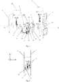
- Fig. 1 illustrates an exploded view of an operating mechanism for a dual power supply changeover switch according to an embodiment of the present disclosure.
- the dual power supply changeover switch can be switched among a dual-off position, a first power-on position and a second power-on position.
- the operating mechanism includes a first supporting plate 1, a second supporting plate 2 and a third supporting plate 3, which are parallel to each other and spaced apart from each other.
- the third supporting plate 3 is located between the first supporting plate 1 and the second supporting plate 2.
- the operating mechanism also includes a plurality of first supporting members 24 for fixing the first supporting plate 1 and the second supporting plate 2 together.
- the first supporting members 24 pass through corresponding holes in the third supporting plate 3.
- the operating mechanism also includes a second supporting member 25 for fixing the first supporting plate 1 and the third supporting plate 3 together, and a third supporting member 26 for fixing the second supporting plate 2 and the third supporting plate 3 together.
- the amount of the second supporting member 25 is two, and the two second supporting members 25 are symmetrical about a symmetry plane A.
- the operating mechanism may not include the third supporting plate 3.
- the operating mechanism further includes a first electromagnet assembly 12 and a second electromagnet assembly 13 symmetrically mounted on the first supporting plate 1 and the second supporting plate 2 about a symmetry plane A.
- the operating mechanism also includes an output assembly, which is mounted on the first supporting plate 1 and the second supporting plate 2 along a rotation axis Z located in the symmetry plane A and is capable of rotating about the rotation axis Z.
- the output assembly includes a rotating shaft 4, a rotating disc 5, a first driving disc 8 and a first driving rod 9.
- the rotating shaft 4 is mounted on the first supporting plate 1 and the second supporting plate 2 along the rotation axis Z, and may be located between the first supporting plate 1 and the second supporting plate 2 or protrude from one of the two supporting plates.
- the rotating shaft 4 is mounted in corresponding holes in the first supporting plate 1 and the second supporting plate 2 through a hole (not illustrated) in the third supporting plate 3.
- the rotating disc 5 is mounted on the rotating shaft 4 and is capable of rotating about the rotating shaft 4.
- the first driving disc 8 is mounted on the rotating shaft 4 and is capable of rotating in cooperation with the rotating disc 5 when the rotating disc 5 rotates.
- the first driving rod 9 is fixed on the first driving disc 8, protrudes out of an opening 10 in the second supporting plate 2 and is connected to a movable contact carrier of the dual power supply changeover switch.
- the first driving rod 9 is capable of driving the movable contact carrier to rotate when the first driving disc 8 rotates, so that the dual power supply changeover switch can be switched among the dual-off position, the first power-on position and the second power-on position.
- the opening 10 in the second supporting plate 2 is provided so that the first driving rod 9 is capable of rotating therein without any obstruction.
- the first supporting plate 1 may also be provided with an opening 10 with a corresponding shape for bidirectional output, the details of which will be described later.
- the first electromagnet assembly 12 and the second electromagnet assembly 13 can be movable upwards to drive the output assembly to rotate in opposite, first and second directions respectively, and then drive the movable contact carrier to rotate through the first driving rod 9.
- the first electromagnet assembly 12 drives the rotating disc 5 to rotate clockwise around the rotation axis Z
- the second electromagnet assembly 13 drives the rotating disc 5 to rotate counterclockwise around the rotation axis Z.
- the operating mechanism further includes a first elastic member 6 and a second elastic member 7 symmetrically arranged about the symmetry plane A.
- One end of the first elastic member 6 abuts against the output assembly (for example, the rotating disc 5), and the other end is mounted between the first supporting plate and the third supporting plate through a pivot shaft of the first elastic member 6.
- the first elastic member 6 and the second elastic member 7 are mounted between the first supporting plate 1 and the second supporting plate 2, respectively.
- the first elastic member 6 can store an energy when the output assembly (e.g., the rotating disc 5) rotates and can release the energy after passing through a "dead point" so as to drive the output assembly to rotate further.
- the second elastic member 7 abuts against the output assembly (e.g., the rotating disc 5), and the other end is mounted between the first supporting plate and the third supporting plate through a pivot shaft of the second elastic member 7.
- the second elastic member 7 can store an energy when the output assembly (for example, the rotating disc 5) rotates and can release the energy after passing through a "dead point" so as to drive the output assembly to rotate further.
- the first electromagnet assembly 12 drives the rotating disc 5 to rotate in the clockwise direction (the first direction) around the rotation axis
- the second elastic member 7 stores an energy
- the second elastic member 7 releases the energy after passing through the "dead point” so as to drive the rotating disc 5 to rotate further in the clockwise direction around the rotation axis Z.
- the second electromagnetic component 13 drives the rotating disc 5 to rotate in the counterclockwise direction (the second direction) around the rotation axis Z
- the first elastic member 6 stores an energy
- the first elastic member 6 releases the energy after passing through the "dead point” so as to drive the rotating disc 5 to rotate further in the counterclockwise direction around the rotation axis Z.
- the switching between different positions of the dual power supply changeover switch can be realized.
- each of the first supporting plate 1 and the third supporting plate 3 is provided with a plurality of first holes 11, for example, two first holes, for mounting pivot shafts of the first elastic member 6 and the second elastic member 7, and the plurality of first holes 11 are arranged symmetrically with respect to the symmetry plane A.
- the first supporting plate 1 and the second supporting plate 2 are respectively provided with third holes 14 and 15, the third holes 14 and 15 are symmetrical about the symmetry plane A and are configured to mount the first electromagnet assembly 12 and the second electromagnet assembly 13, respectively.
- the operating mechanism can be arranged at the left or right side of the breaking unit.
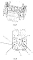
- the operating mechanism provides a right-side driving mode, and the perspective view of the operating mechanism at this time is illustrated in the figure at the upper left corner of Fig. 5 .
- the operating mechanism provides a left-side driving mode, and the perspective view of the operating mechanism at this time is illustrated in the figure at the upper right corner of Fig. 5 .
- the first driving disc in the figure at the upper right corner of Fig. 5 is reversely mounted on the rotating shaft with respect to the first driving disc in the figure at the upper left corner of Fig. 5 ; however, in other examples, the installation of the first driving disc may be unchanged.
- two operating mechanisms can be mounted for one breaking unit; the two operating mechanisms are located at opposite sides of the breaking unit, as illustrated in Fig. 7 . In this case, it can provide more power for the conversion process, and such operating mechanism can also be applied to the situation of high rated current.
- the operating mechanism can realize the left-side driving mode and the right-side driving mode, as illustrated in the upper, two figures of Fig. 5 .
- a driving mode at the positions illustrated in the lower, two figures of Fig. 5 can be realized, which can be applied to switches with wire inlet terminals at different positions.
- the operating mechanism of the present disclosure can also be applied to the breaking unit with high rated current, as illustrated in Fig. 7 . Therefore, the operating mechanism of the present disclosure can be flexibly assembled according to the position of the movable contact of the breaking unit, so as to meet the requirements of different application situations, decrease the types of components and parts, reduce the cost and improve the reliability.
- the output assembly further includes a transmission disc 18, which is mounted on the rotating shaft 4 and is capable of driving the first driving disc 8 to rotate when the rotating disc 5 rotates.
- the transmission disc 18 includes tooth parts 19 symmetrical about the symmetry plane A.
- the transmission disc 18 may be formed integrally with the rotating disc 5.
- the operating mechanism further includes a manual operating member 16, which has a mounting shaft 27 and is mounted between the second supporting plate and the third supporting plate through the mounting shaft 27.
- a manual operating member 16 which has a mounting shaft 27 and is mounted between the second supporting plate and the third supporting plate through the mounting shaft 27.
- Each of the second supporting plate 2 and the third supporting plate 3 is provided with a plurality of second holes 17, for example, two second holes, for the mounting shaft 27, and the plurality of second holes 17 are arranged symmetrically with respect to the symmetry plane.
- the mounting shaft 27 is arranged between the second supporting plate and the third supporting plate through two second holes 17 at corresponding positions in the second supporting plate and the third supporting plate.
- the manual operating member 16 is located at the left side of the symmetry plane A, and tooth parts 20 of the manual operating member 16 are engaged with the tooth parts 19 of the transmission disc 18 so as to rotate the transmission disc 18 under a manual operation, thereby driving the first driving disc 8 to rotate.
- the manual operating member 16 may be located at the left side of the symmetry plane A, as illustrated in the left-side figure of Fig. 9 .
- the manual operating member 16 may also be located at the right side of the symmetry plane A, as illustrated in the right-side figure of Fig. 9 .
- the two positions of the manual operating member 16 in Fig. 9 are symmetrical about the symmetry plane A. In this way, the operating mechanism can provide flexible manual operation positions to be suitable for different application situations.
- the manual operating member 16 can drive the transmission disc 18 to rotate so as to realize the rotation of the driving rod 9.
- the operating mechanism further includes a second driving disc 21, a second driving rod 22 and a transmission rod 23.
- the second driving disc 21 is mounted on the rotating shaft 4, located near the first supporting plate 1, away from the first driving disc 8, for example, located at an outer side of the first supporting plate 1 as illustrated in the figure. In other examples, the second driving disc 21 may also be located at an inner side of the first supporting plate 1.
- the transmission rod 23 connects the second driving disc 21 with the first driving disc 8 so that the second driving disc 21 can rotate together with the first driving disc 8. As illustrated in Fig. 11 , the transmission rod 23 passes through the opening 10 in the first supporting plate 1 to connect the second driving disc 21 with the first driving disc 8.
- the transmission rod 23 is connected to the first driving disc 8 by a pin located at an end of the transmission rod 23, as illustrated in Figs. 12 and 13 .
- the second driving rod 22 is fixed on the second driving disc 21, protrudes out of the operating mechanism from a side opposite to the first driving rod 9 (for example, along the horizontal, right direction in Fig. 11 ), and is connected to another movable contact carrier so as to be capable of rotating the another movable contact carrier when the first driving disc 8 rotates.
- the second driving rod may protrude from the opening 10 in the first supporting plate 1.
- the operating mechanism of the present disclosure can realize the output in two directions, and can drive the breaking units at both sides of the operating mechanism respectively, thereby providing more flexible configuration, stable driving mode and higher reliability.
Landscapes
- Mechanisms For Operating Contacts (AREA)
- Driving Mechanisms And Operating Circuits Of Arc-Extinguishing High-Tension Switches (AREA)
Applications Claiming Priority (1)
| Application Number | Priority Date | Filing Date | Title |
|---|---|---|---|
| CN202021203315.3U CN213025884U (zh) | 2020-06-24 | 2020-06-24 | 用于双电源转换开关的操作机构和双电源转换开关 |
Publications (2)
| Publication Number | Publication Date |
|---|---|
| EP3933869A1 true EP3933869A1 (de) | 2022-01-05 |
| EP3933869B1 EP3933869B1 (de) | 2026-04-01 |
Family
ID=75498189
Family Applications (1)
| Application Number | Title | Priority Date | Filing Date |
|---|---|---|---|
| EP21305856.3A Active EP3933869B1 (de) | 2020-06-24 | 2021-06-23 | Betätigungsmechanismus für doppelstromversorgungwechselschalter sowie doppelstromversorgungwechselschalter |
Country Status (3)
| Country | Link |
|---|---|
| EP (1) | EP3933869B1 (de) |
| CN (1) | CN213025884U (de) |
| AU (1) | AU2021204251B2 (de) |
Cited By (3)
| Publication number | Priority date | Publication date | Assignee | Title |
|---|---|---|---|---|
| CN114743811A (zh) * | 2022-04-27 | 2022-07-12 | 北京海博思创科技股份有限公司 | 铜排组件和电源切换开关 |
| EP4258308A1 (de) * | 2022-04-08 | 2023-10-11 | Schneider Electric Industries SAS | Betätigungsmechanismus für einen zweistrom-umschalter und zweistrom-umschalter |
| CN118538554A (zh) * | 2024-07-26 | 2024-08-23 | 厦门顾德益电气股份有限公司 | 开关主轴传动装置及气体柜 |
Families Citing this family (1)
| Publication number | Priority date | Publication date | Assignee | Title |
|---|---|---|---|---|
| CN216624025U (zh) * | 2021-12-30 | 2022-05-27 | 施耐德电器工业公司 | 电磁铁驱动机构、组件和双电源自动转换开关 |
Citations (3)
| Publication number | Priority date | Publication date | Assignee | Title |
|---|---|---|---|---|
| US20080245645A1 (en) * | 2007-04-09 | 2008-10-09 | Asco Power Technologies, L.P. | Three-position apparatus capable of positioning an electrical transfer switch |
| EP3567622A1 (de) * | 2018-05-04 | 2019-11-13 | Schneider Electric Industries SAS | Doppelstromversorgungstransferschalter und schaltmechanismus dafür |
| CN210743822U (zh) * | 2019-12-31 | 2020-06-12 | 常熟开关制造有限公司(原常熟开关厂) | 一种双电源转换开关的合分闸机构 |
-
2020
- 2020-06-24 CN CN202021203315.3U patent/CN213025884U/zh active Active
-
2021
- 2021-06-23 AU AU2021204251A patent/AU2021204251B2/en active Active
- 2021-06-23 EP EP21305856.3A patent/EP3933869B1/de active Active
Patent Citations (3)
| Publication number | Priority date | Publication date | Assignee | Title |
|---|---|---|---|---|
| US20080245645A1 (en) * | 2007-04-09 | 2008-10-09 | Asco Power Technologies, L.P. | Three-position apparatus capable of positioning an electrical transfer switch |
| EP3567622A1 (de) * | 2018-05-04 | 2019-11-13 | Schneider Electric Industries SAS | Doppelstromversorgungstransferschalter und schaltmechanismus dafür |
| CN210743822U (zh) * | 2019-12-31 | 2020-06-12 | 常熟开关制造有限公司(原常熟开关厂) | 一种双电源转换开关的合分闸机构 |
Cited By (5)
| Publication number | Priority date | Publication date | Assignee | Title |
|---|---|---|---|---|
| EP4258308A1 (de) * | 2022-04-08 | 2023-10-11 | Schneider Electric Industries SAS | Betätigungsmechanismus für einen zweistrom-umschalter und zweistrom-umschalter |
| AU2023202030B2 (en) * | 2022-04-08 | 2024-01-25 | Schneider Electric Industries Sas | Operating mechanism for dual-power changeover switch and dual-power changeover switch |
| CN114743811A (zh) * | 2022-04-27 | 2022-07-12 | 北京海博思创科技股份有限公司 | 铜排组件和电源切换开关 |
| CN114743811B (zh) * | 2022-04-27 | 2023-09-26 | 北京海博思创科技股份有限公司 | 铜排组件和电源切换开关 |
| CN118538554A (zh) * | 2024-07-26 | 2024-08-23 | 厦门顾德益电气股份有限公司 | 开关主轴传动装置及气体柜 |
Also Published As
| Publication number | Publication date |
|---|---|
| CN213025884U (zh) | 2021-04-20 |
| AU2021204251B2 (en) | 2022-08-25 |
| EP3933869B1 (de) | 2026-04-01 |
| AU2021204251A1 (en) | 2022-01-20 |
Similar Documents
| Publication | Publication Date | Title |
|---|---|---|
| EP3933869B1 (de) | Betätigungsmechanismus für doppelstromversorgungwechselschalter sowie doppelstromversorgungwechselschalter | |
| EP4451539A2 (de) | Schalter, leistungsumwandlungsvorrichtung und stromversorgungssystem | |
| US8723069B2 (en) | Viewing window and ground contact connection for a high-voltage arrangement | |
| EP4254462B1 (de) | Betriebssystem eines miniaturschutzschalters und miniaturschutzschalter damit | |
| US20190304713A1 (en) | Automatic Power Transfer Switching Mechanism | |
| WO2021155565A1 (en) | Disconnector for switchgear | |
| RU2777724C1 (ru) | Исполнительный механизм для переключателя питания от двух источников и переключатель питания от двух источников | |
| CN220796550U (zh) | 一种执行机构、转换开关及配电设备 | |
| CN118053683A (zh) | 转换开关的传动结构及转换开关 | |
| CN105428116A (zh) | 双电源切换机构以及自动转换开关 | |
| EP4258308B1 (de) | Betätigungsmechanismus für einen zweistrom-umschalter und zweistrom-umschalter | |
| CN110534365B (zh) | 一种两位置储能型转换开关装置 | |
| CN210123696U (zh) | 一种三工位电动机构止位装置 | |
| CN109509647B (zh) | 一种操作机构及其开关装置 | |
| CN223296684U (zh) | 用于开关设备的三相连接的传动装置和开关设备 | |
| CN114758919B (zh) | 隔离开关和开关柜 | |
| CN222507382U (zh) | 操作机构及转换开关 | |
| CN216698143U (zh) | 一种旁路型双电源自动转换开关联锁装置 | |
| CN218769353U (zh) | 双电源联锁装置 | |
| CN113012954B (zh) | 三工位操作机构及具有其的开关设备 | |
| CN212412834U (zh) | 双电源转换开关和开关柜 | |
| CN118942946A (zh) | 一种控制型负载转换开关 | |
| CN121260684A (zh) | 模组型带零位转换开关装置 | |
| CN120261189A (zh) | 用于开关装置的传动机构和开关装置 | |
| CN103295830B (zh) | 气体绝缘或真空绝缘的配电板中的配电装置 |
Legal Events
| Date | Code | Title | Description |
|---|---|---|---|
| PUAI | Public reference made under article 153(3) epc to a published international application that has entered the european phase |
Free format text: ORIGINAL CODE: 0009012 |
|
| STAA | Information on the status of an ep patent application or granted ep patent |
Free format text: STATUS: THE APPLICATION HAS BEEN PUBLISHED |
|
| AK | Designated contracting states |
Kind code of ref document: A1 Designated state(s): AL AT BE BG CH CY CZ DE DK EE ES FI FR GB GR HR HU IE IS IT LI LT LU LV MC MK MT NL NO PL PT RO RS SE SI SK SM TR |
|
| B565 | Issuance of search results under rule 164(2) epc |
Effective date: 20211206 |
|
| STAA | Information on the status of an ep patent application or granted ep patent |
Free format text: STATUS: REQUEST FOR EXAMINATION WAS MADE |
|
| 17P | Request for examination filed |
Effective date: 20220704 |
|
| RBV | Designated contracting states (corrected) |
Designated state(s): AL AT BE BG CH CY CZ DE DK EE ES FI FR GB GR HR HU IE IS IT LI LT LU LV MC MK MT NL NO PL PT RO RS SE SI SK SM TR |
|
| STAA | Information on the status of an ep patent application or granted ep patent |
Free format text: STATUS: EXAMINATION IS IN PROGRESS |
|
| 17Q | First examination report despatched |
Effective date: 20250225 |
|
| GRAP | Despatch of communication of intention to grant a patent |
Free format text: ORIGINAL CODE: EPIDOSNIGR1 |
|
| STAA | Information on the status of an ep patent application or granted ep patent |
Free format text: STATUS: GRANT OF PATENT IS INTENDED |
|
| RIC1 | Information provided on ipc code assigned before grant |
Ipc: H01H 3/40 20060101AFI20251014BHEP Ipc: H01H 3/42 20060101ALI20251014BHEP Ipc: H01H 3/30 20060101ALN20251014BHEP Ipc: H01H 3/28 20060101ALN20251014BHEP |
|
| INTG | Intention to grant announced |
Effective date: 20251029 |
|
| GRAS | Grant fee paid |
Free format text: ORIGINAL CODE: EPIDOSNIGR3 |
|
| GRAA | (expected) grant |
Free format text: ORIGINAL CODE: 0009210 |
|
| STAA | Information on the status of an ep patent application or granted ep patent |
Free format text: STATUS: THE PATENT HAS BEEN GRANTED |
|
| AK | Designated contracting states |
Kind code of ref document: B1 Designated state(s): AL AT BE BG CH CY CZ DE DK EE ES FI FR GB GR HR HU IE IS IT LI LT LU LV MC MK MT NL NO PL PT RO RS SE SI SK SM TR |
|
| REG | Reference to a national code |
Ref country code: CH Ref legal event code: F10 Free format text: ST27 STATUS EVENT CODE: U-0-0-F10-F00 (AS PROVIDED BY THE NATIONAL OFFICE) Effective date: 20260401 Ref country code: GB Ref legal event code: FG4D |
|
| REG | Reference to a national code |
Ref country code: IE Ref legal event code: FG4D |
|
| REG | Reference to a national code |
Ref country code: DE Ref legal event code: R096 Ref document number: 602021051053 Country of ref document: DE |