EP4258308B1 - Betätigungsmechanismus für einen zweistrom-umschalter und zweistrom-umschalter - Google Patents
Betätigungsmechanismus für einen zweistrom-umschalter und zweistrom-umschalter Download PDFInfo
- Publication number
- EP4258308B1 EP4258308B1 EP23305450.1A EP23305450A EP4258308B1 EP 4258308 B1 EP4258308 B1 EP 4258308B1 EP 23305450 A EP23305450 A EP 23305450A EP 4258308 B1 EP4258308 B1 EP 4258308B1
- Authority
- EP
- European Patent Office
- Prior art keywords
- dual
- operating mechanism
- changeover switch
- driving
- power
- Prior art date
- Legal status (The legal status is an assumption and is not a legal conclusion. Google has not performed a legal analysis and makes no representation as to the accuracy of the status listed.)
- Active
Links
Images


Classifications
-
- H—ELECTRICITY
- H01—ELECTRIC ELEMENTS
- H01H—ELECTRIC SWITCHES; RELAYS; SELECTORS; EMERGENCY PROTECTIVE DEVICES
- H01H3/00—Mechanisms for operating contacts
- H01H3/02—Operating parts, i.e. for operating driving mechanism by a mechanical force external to the switch
-
- H—ELECTRICITY
- H01—ELECTRIC ELEMENTS
- H01H—ELECTRIC SWITCHES; RELAYS; SELECTORS; EMERGENCY PROTECTIVE DEVICES
- H01H3/00—Mechanisms for operating contacts
- H01H3/32—Driving mechanisms, i.e. for transmitting driving force to the contacts
-
- H—ELECTRICITY
- H01—ELECTRIC ELEMENTS
- H01H—ELECTRIC SWITCHES; RELAYS; SELECTORS; EMERGENCY PROTECTIVE DEVICES
- H01H3/00—Mechanisms for operating contacts
- H01H3/32—Driving mechanisms, i.e. for transmitting driving force to the contacts
- H01H3/40—Driving mechanisms, i.e. for transmitting driving force to the contacts using friction, toothed, or screw-and-nut gearing
-
- H—ELECTRICITY
- H01—ELECTRIC ELEMENTS
- H01H—ELECTRIC SWITCHES; RELAYS; SELECTORS; EMERGENCY PROTECTIVE DEVICES
- H01H3/00—Mechanisms for operating contacts
- H01H3/32—Driving mechanisms, i.e. for transmitting driving force to the contacts
- H01H3/46—Driving mechanisms, i.e. for transmitting driving force to the contacts using rod or lever linkage, e.g. toggle
-
- H—ELECTRICITY
- H01—ELECTRIC ELEMENTS
- H01H—ELECTRIC SWITCHES; RELAYS; SELECTORS; EMERGENCY PROTECTIVE DEVICES
- H01H9/00—Details of switching devices, not covered by groups H01H1/00 - H01H7/00
- H01H9/20—Interlocking, locking, or latching mechanisms
- H01H9/26—Interlocking, locking, or latching mechanisms for interlocking two or more switches
-
- H—ELECTRICITY
- H01—ELECTRIC ELEMENTS
- H01H—ELECTRIC SWITCHES; RELAYS; SELECTORS; EMERGENCY PROTECTIVE DEVICES
- H01H9/00—Details of switching devices, not covered by groups H01H1/00 - H01H7/00
- H01H9/20—Interlocking, locking, or latching mechanisms
- H01H9/26—Interlocking, locking, or latching mechanisms for interlocking two or more switches
- H01H2009/267—Interlocking, locking, or latching mechanisms for interlocking two or more switches with interlocking of two out of three switches, e.g. two switches each connecting a power supply to a busbar and a bus coupling switch interlocked in such a way that the power supplies are never connected in parallel
-
- H—ELECTRICITY
- H01—ELECTRIC ELEMENTS
- H01H—ELECTRIC SWITCHES; RELAYS; SELECTORS; EMERGENCY PROTECTIVE DEVICES
- H01H2300/00—Orthogonal indexing scheme relating to electric switches, relays, selectors or emergency protective devices covered by H01H
- H01H2300/018—Application transfer; between utility and emergency power supply
Definitions
- the present disclosure relates to an operating mechanism for a dual-power changeover switch and a dual-power changeover switch.
- Dual-power changeover switches are widely used in industrial fields, especially in emergency power supply systems or places where power outage is not permitted. Based on the status of a power supply circuit, the dual-power changeover switch allows a load circuit connected to one power supply to be connected to another power supply, for example, switching between commercial power grid and standby power supply, thus maintaining continuous and reliable operation of the load circuit.
- the dual-power changeover switch can also be divided into different housing frames according to the current level.
- the demand for dual-power changeover switch is relatively small.
- it is an extremely effective means to reuse components and parts for housing frames of different current levels to the maximum extent.
- Dual-power changeover switch is generally divided into two portions, which are an operating mechanism and a breaking unit, respectively.
- the operating mechanism transfers energy to a movable contact carrier of the breaking unit so that the movable contact performs opening and closing motions.
- the reused module can be the operating mechanism of the dual-power changeover switch.
- the breaking unit can also be reused to a certain extent. Such layout is especially suitable for products with smaller demand and larger number of components and parts.
- EP 3 933 869 A1 discloses an operating mechanism for a dual power supply changeover switch capable of switching among a dual-off position, a first power-on position and a second power-on position.
- the operating mechanism includes: a first supporting plate and a second supporting plate which are parallel to each other and spaced apart from each other; a plurality of first supporting members configured to fix the first supporting plate and the second supporting plate together; a first electromagnet assembly and a second electromagnet assembly which are symmetrically mounted on the first supporting plate and the second supporting plate about a symmetry plane; and an output assembly mounted on the first supporting plate and the second supporting plate along a rotation axis in the symmetry plane, the output assembly is capable of rotating around the rotation axis and has a first driving rod, the first driving rod protrudes from the second supporting plate and is connected to a movable contact carrier.
- the first electromagnet assembly and the second electromagnet assembly are configured to drive the output assembly to rotate in a first direction and a second direction which are opposite to each other
- the purpose of the present disclosure is to provide an operating mechanism for a dual-power changeover switch and a dual-power changeover switch. Such an operating mechanism can ensure that a dual-power changeover switch reusing a modular unit can perform reliable synchronous switching, with simple structure and low cost.
- the present disclosure provides an operating mechanism for a dual-power changeover switch, the operating mechanism is configured to drive breaking units of poles of the dual-power changeover switch simultaneously, so that the dual-power changeover switch can be switched between different states.
- the operating mechanism includes: a manual operating device arranged on a first side of a housing of the dual-power changeover switch and configured to rotate around a rotation axis under the action of a driving force; a synchronizing rod connected to the manual operating device in a transmission way, including a first end located close to the first side and a second end located close to a second side of the housing opposite to the first side, and configured to be rotatable around an extension direction of the synchronizing rod when the manual operating device rotates; a first driving member arranged on the first end of the synchronizing rod and connected with a first driving disc assembly at a first end of a main shaft shared by the breaking units of the poles; and a second driving member arranged on the second end of the synchronizing rod and connected with a second
- the operating mechanism further includes a first transmission assembly arranged on the first side of the housing and a second transmission assembly arranged on the second side of the housing, wherein the first transmission assembly is arranged between the first driving member and the first driving disc assembly, and the second transmission assembly is arranged between the second driving member and the second driving disc assembly.
- first transmission assembly and the second transmission assembly are the same and are each provided with at least one gear.
- first driving member and the second driving member are the same and are each in the form of a gear.
- first driving member and the second driving member are respectively connected with the first end and the second end of the synchronizing rod through spline connectors.
- the spline connector has an arc surface.
- the operating mechanism further includes a third transmission assembly, which is connected with the first driving member and configured to drive the first driving member to rotate when the manual operating device rotates, thereby driving the synchronizing rod to rotate.
- the third transmission assembly includes at least one gear.
- the main shaft is movable between a first position corresponding to a first power-on state of the dual-power changeover switch and a second position corresponding to a second power-on state of the dual-power changeover switch.
- the main shaft is movable among a first position corresponding to a first power-on state of the dual-power changeover switch, a dual-separation position corresponding to a dual-separation state of the dual-power changeover switch, and a second position corresponding to a second power-on state of the dual-power changeover switch.
- the first driving disc assembly and the second driving disc assembly are configured to be rotatable when driven by an electromagnetic operating mechanism of the dual-power changeover switch, thereby driving the main shaft to perform the opening motion and the closing motion.
- the first driving disc assembly includes a first protrusion arranged thereon
- the second driving disc assembly includes a second protrusion arranged thereon, wherein the first protrusion is connected to the first end of the main shaft, and the second protrusion is connected to the second end of the main shaft.
- the rotation axis and an extension direction of the synchronizing rod are parallel to an extension direction of the main shaft, respectively.
- the present disclosure also provides a dual-power changeover switch, which includes the operating mechanism as described above.
- the dual-power changeover switch 100 shown in Fig. 1 includes four poles which are A, B, C and N, respectively. In some other embodiments, the dual-power changeover switch may include three poles, which is not limited in the present disclosure.
- the dual-power changeover switch of the present disclosure can be used for a large current of about 630A, for example. Of course, the dual-power changeover switch of the present disclosure can also be used for larger current, which is not limited in the present disclosure.
- the width of the dual-power changeover switch of the present disclosure i.e., the sum of the widths of all the poles
- a main shaft 102 shared by breaking units of all the poles of the dual-power changeover switch is an elongate shaft.
- a main shaft 102 shared by breaking units of all the poles of the dual-power changeover switch is an elongate shaft.
- such elongate shaft when driven at a single side, it may lead to inconsistent torsions of various portions of the main shaft, resulting in nonsynchronous opening and closing motions of the breaking units of various poles.
- the "main shaft shared by all the poles” mentioned here refers to a common shaft that can drive the opening and closing motions of the movable contact carrier of the breaking unit of each of the poles, and the main shaft extends to pass through the movable contact carriers of the breaking units of all the poles.
- the operating mechanism according to the present disclosure can simultaneously drive the breaking units of various poles of the dual-power changeover switch, especially driving from both sides of the dual-power changeover switch, so that the dual-power changeover switch can be switched between different states.
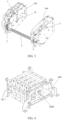
- the operating mechanism includes a manual operating device 1, a synchronizing rod 2, a first driving member 3, and a second driving member 4.
- the manual operating device 1 is arranged on a first side of a housing 101 of the dual-power changeover switch 100 and is configured to rotate around a rotation axis under the action of a driving force.
- the "housing” mentioned here refers to the entirety of all the housing frames on which various components and parts of the dual-power changeover switch are arranged.
- the manual operating device 1 is arranged on the first side at the left of the figure.
- the manual operating device 1 can be arranged on a left housing frame 103, as shown in Figs. 2 and 3 .
- the manual operating device 1 can be a manual operating panel, which is arranged on the housing frame 103 through a rotation shaft of the manual operating panel, with a rotation axis of the manual operating panel shown as "A" in the figure.
- the manual operating device 1 can also be arranged on a right housing frame 104, that is, on a second side of the housing 101 opposite to the first side. It should be noted that the operating mechanism of the present disclosure only has the manual operating device arranged at one of its sides.
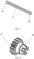
- the synchronizing rod 2 is connected to the manual operating device 1 in a transmission way, and includes a first end 21 located close to the first side of the housing 101 and a second end 22 located close to the second side of the housing 101 opposite to the first side, and is configured to rotate around its extension direction when the manual operating device 1 rotates.
- the synchronizing rod 2 is rotatably arranged on the housing 101, for example, on the left housing frame 103 and the right housing frame 104.
- the first driving member 3 is arranged on the first end 21 of the synchronizing rod 2 and connected with a first driving disc assembly 5 at a first end of the main shaft 102 shared by the breaking units of all the poles.
- the first end of the main shaft 102 is located close to the first side of the housing 101, that is, the first end is a left end. It can be considered that the first driving disc assembly 5 is located on the first side of the housing 101, for example, it's arranged on the left housing frame 103.
- the second driving member 4 is arranged on the second end 22 of the synchronizing rod 2 and connected with a second driving disc assembly 6 at a second end of the main shaft 102.
- the second end of the main shaft 102 is located close to the second side of the housing 101, that is, the second end is a right end. It can be considered that the second driving disc assembly 6 is located on the second side of the housing 101, for example, it's arranged on the right housing frame 104.
- the first driving disc assembly 5 and the second driving disc assembly 6 are configured to be capable of rotating when driven by an electromagnetic operating mechanism of the dual-power changeover switch, thereby driving the main shaft to perform opening and closing motions. That is to say, the first driving disc assembly 5 and the second driving disc assembly 6 are part of an automatic operating mechanism of the dual-power changeover switch.
- the electromagnetic operating mechanism includes electromagnets 13, 14, 15 and 16 shown in Fig. 6 .
- the electromagnets 13 and 14 are located on the first side of the housing 101, and the electromagnets 15 and 16 are located on the second side of the housing 101, for example, on their respective housing frames. Additionally, as shown in Fig.
- the first driving disc assembly 5 includes a first central turntable 51 and a first driving disc 52 coaxially arranged on the left side of the housing 101
- the second driving disc assembly 6 includes a second central turntable 61 and a second driving disc 62 coaxially arranged on the right side of the housing 101.
- the first central turntable 51 is rotatable around its rotation shaft when driven by the electromagnets 13 and 14, thereby driving the first driving disc 52 to rotate therewith.
- the second central turntable 61 is rotatable around its rotation shaft when driven by the electromagnets 15 and 16, thereby driving the second driving disc 62 to rotate therewith.
- the first driving disc assembly 5 includes a first protrusion 53 provided thereon
- the second driving disc assembly 6 includes a second protrusion 63 provided thereon.
- the first protrusion 53 is connected to the first end (i.e., the left end) of the main shaft 102
- the second protrusion 63 is connected to the second end (i.e., the right end) of the main shaft 102.
- the first protrusion 53 is in the form of a pin, which is arranged on the first driving disc 52 and inserted into a groove on a left crank arm 1021 of the main shaft 102 by passing through the left housing frame 103 of the housing 101.
- the second protrusion 63 is also in the form of a pin, which is arranged on the second driving disc 62 and inserted into a groove on a right crank arm 1022 of the main shaft 102 by passing through the right housing frame 104 of the housing 101.
- the first protrusion 53 and the second protrusion 63 may also have other forms.
- the first central turntable 51 and the first driving disc 52, as well as the second central turntable 61 and the second driving disc 62 can rotate together in the counterclockwise direction in Fig. 6 , thereby driving the main shaft to move to a first position corresponding to a first power-on state of the dual-power changeover switch, for example.
- the first central turntable 51 and the first driving disc 52, as well as the second central turntable 61 and the second driving disc 62 can rotate together in the clockwise direction in Fig. 6 , thereby driving the main shaft to move to a second position corresponding to a second power-on state of the dual-power changeover switch, for example.
- the first central turntable 51 and the first driving disc 52, as well as the second central turntable 61 and the second driving disc 62 can also collectively drive the main shaft to move to a dual-separation position corresponding to a dual-separation state of the dual-power changeover switch.
- the first driving member 3 and the second driving member 4 as described above are configured to simultaneously rotate in the same direction around the synchronizing rod 2 as a rotation shaft when the synchronizing rod 2 rotates, so as to drive the first driving disc assembly 5 and the second driving disc assembly 6 to rotate, thereby driving the main shaft to perform opening motion and closing motion.
- the main shaft 102 can move between the first position corresponding to the first power-on state of the dual-power changeover switch and the second position corresponding to the second power-on state of the dual-power changeover switch, or, the main shaft 102 can move among the first position corresponding to the first power-on state of the dual-power changeover switch, the dual-separation position corresponding to the dual-separation state of the dual-power changeover switch, and the second position corresponding to the second power-on state of the dual-power changeover switch.
- the first driving member 3 and the second driving member 4 may be exactly the same, for example, both in the form of gears.
- first driving member 3 and the second driving member 4 may be exactly the same gears with the same size and the same form of teeth.
- the first driving member 3 and the second driving member 4 can simultaneously rotate in the counterclockwise direction in Fig. 6 or simultaneously rotate in the clockwise direction in Fig. 6 .
- the manual operating device 1 and the electromagnets 13, 14 in the operating mechanism of the present disclosure can be used for driving a small-current dual-power changeover switch at a single side.
- the operating mechanism of the present disclosure reuses the module(s) of the low-current dual-power changeover switch by adding electromagnets 15 and 16, which reduces the manufacturing cost, the designing cost and the product cost.
- the main shaft is driven simultaneously at both sides by using the synchronizing rod as well as the first driving member and second driving member which rotate coaxially. In this way, the occurrence of nonsynchronous opening and closing motions of various poles due to the torsion of the main shaft is reduced, and the reliable synchronous switching can be ensured in the high-current dual-power changeover switch.
- the operating mechanism also includes a first transmission assembly 7 arranged on the first side of the housing 101 and a second transmission assembly 8 arranged on the second side of the housing 101.
- the first transmission assembly 8 is arranged between the first driving member 3 and the first driving disc assembly 5, and the second transmission assembly 8 is arranged between the second driving member 4 and the second driving disc assembly 6.
- the first transmission assembly 7 and the second transmission assembly 8 are exactly the same.
- the first transmission assembly 7 and the second transmission assembly 8 are each provided with at least one gear.
- the first transmission assembly 7 and the second transmission assembly 8 are each provided with one gear.
- the first transmission assembly 7 engages with the first driving member 3 in the form of gear and the teeth of the first central turntable 51 of the first driving disc assembly 5, respectively
- the second transmission assembly 8 engages with the second driving member 4 in the form of gear and the teeth of the second central turntable 61 of the second driving disc assembly 6, respectively.
- the transmission torque of the synchronizing rod 2 can be reduced.
- the transmission torque of the operating mechanism of the present disclosure is about 4 N ⁇ m.
- the first driving member 3 and the second driving member 4 are respectively connected with the first end 21 and the second end 22 of the synchronizing rod 2 through spline connectors 9.
- the spline connector 9 has an arc surface. This structure can ensure accurate and tight transmission of torque.
- the operating mechanism also includes a third transmission assembly 10, which is arranged between the manual operating device 1 and the synchronizing rod 2 and transmits the driving force of the manual operating device 1 to the synchronizing rod 2.
- the third transmission assembly 10 is connected with the first driving member 3, and is configured to drive the first driving member 3 to rotate when the manual operating device 1 rotates, thereby driving the synchronizing rod 2 to rotate, so that the first driving member 3 and the second driving member 4 can rotate simultaneously in the same direction.
- the third transmission assembly 10 may include at least one gear.
- the third transmission assembly 10 includes two gears shown in Fig. 6 .
- the position of the synchronizing rod 2 can be adjusted, so that the current loop (not shown in the figure) of the breaking unit can be bypassed. Additionally, the third transmission assembly 10 can also cooperate with the manual operating device 1, so as to adjust the magnitude of the force for manual operation.
- the rotation axis A of the manual operating device 1 and the extension direction of the synchronizing rod 2 are parallel to the extension direction of the main shaft 102, respectively. In some other embodiments, the rotation axis A of the manual operating device 1 may not be parallel to the extension direction of the synchronizing rod 2.
- the synchronizing rod, the first and second driving members that rotate coaxially, and other transmission assemblies added in the manual operating mechanism of the present disclosure are all driven members which will not be subject to the force exerted by the automatic operating mechanism and will not affect the synchronization of the automatic operation.
- the driving mechanisms at the first side and the second side (i.e., the left side and the right side) of the housing of the dual-power changeover switch are symmetrically arranged, and the driving chains and the directions of polarization at both sides are completely consistent with each other in addition to the introduced deformation and the error of the synchronizing rod per se, which ensures the synchronization of the movement of the first driving disc assembly and the second driving disc assembly to the greatest extent, thereby ensuring the synchronization of the opening and closing motions of the breaking units of various poles of the dual-power changeover switch.
- gears are utilized in the operating mechanism disclosed in the present disclosure for transmission, so that the torque transmitted by the synchronizing rod can be simply and directly adjusted, which leads to simple structure and low costs.
Landscapes
- Physics & Mathematics (AREA)
- Electromagnetism (AREA)
- Driving Mechanisms And Operating Circuits Of Arc-Extinguishing High-Tension Switches (AREA)
- Transmission Devices (AREA)
- Transmitters (AREA)
- Keying Circuit Devices (AREA)
Claims (14)
- Betätigungsmechanismus für einen Doppelleistungsumschalter, wobei der Betätigungsmechanismus konfiguriert ist, um Unterbrechungseinheiten von Polen des Doppelleistungsumschalters (100) gleichzeitig anzutreiben, so dass der Doppelleistungsumschalter zwischen verschiedenen Zuständen umgeschaltet werden kann, wobei der Betätigungsmechanismus umfasst:eine manuelle Betätigungsvorrichtung (1), die auf einer ersten Seite eines Gehäuses (101) des Doppelleistungsumschalters angeordnet ist und konfiguriert ist, um sich unter der Wirkung einer Antriebskraft um eine Drehachse (A) zu drehen;eine Synchronisierstange (2), die mit der manuellen Betätigungsvorrichtung (1) auf eine Übertragungsweise verbunden ist, wobei die Synchronisierstange (2) ein erstes Ende (21), das sich nahe der ersten Seite befindet,und ein zweites Ende (22), das sich nahe einer zweiten Seite des Gehäuses gegenüber der ersten Seite befindet, umfasst, und wobei die Synchronisierstange (2) so konfiguriert ist, dass sie um eine Erstreckungsrichtung der Synchronisierstange (2) drehbar ist, wenn sich die manuelle Betätigungsvorrichtung (1) dreht;ein erstes Antriebselement (3), das am ersten Ende (21) der Synchronisierstange (2) angeordnet ist und mit einer ersten Antriebsscheibenanordnung (5) an einem ersten Ende einer Hauptwelle (102) verbunden ist, die von den Unterbrechungseinheiten der Pole gemeinsam genutzt wird; undein zweites Antriebselement (4), das am zweiten Ende (22) der Synchronisierstange (2) angeordnet ist und mit einer zweiten Antriebsscheibenanordnung (6) an einem zweiten Ende der Hauptwelle (102) verbunden ist,wobei das erste Antriebselement (3) und das zweite Antriebselement (4) konfiguriert sind, um sich gleichzeitig in einer gleichen Richtung mit der Synchronisierstange (2) als eine Drehwelle zu drehen, wenn sich die Synchronisierstange (2) dreht, um die erste Antriebsscheibenanordnung (5) und die zweite Antriebsscheibenanordnung (6) zur Drehung anzutreiben, wodurch die Hauptwelle (102) angetrieben wird, um eine Öffnungsbewegung und eine Schließbewegung auszuführen.
- Betätigungsmechanismus nach Anspruch 1, wobei der Betätigungsmechanismus ferner eine erste Übertragungsanordnung (7), die auf der ersten Seite des Gehäuses (101) angeordnet ist, und eine zweite Übertragungsanordnung (8), die auf der zweiten Seite des Gehäuses (101) angeordnet ist, umfasst, wobei die erste Übertragungsanordnung (7) zwischen dem ersten Antriebselement (3) und der ersten Antriebsscheibenanordnung (5) angeordnet ist und die zweite Übertragungsanordnung (8) zwischen dem zweiten Antriebselement (4) und der zweiten Antriebsscheibenanordnung (6) angeordnet ist.
- Betätigungsmechanismus nach Anspruch 2, wobei die erste Übertragungsanordnung (7) und die zweite Übertragungsanordnung (8) gleich sind und jeweils mit mindestens einem Zahnrad versehen sind.
- Betätigungsmechanismus nach Anspruch 1, wobei das erste Antriebselement (3) und das zweite Antriebselement (4) gleich sind und jeweils in Form eines Zahnrads vorliegen.
- Betätigungsmechanismus nach Anspruch 4, wobei das erste Antriebselement (3) und das zweite Antriebselement (4) jeweils mit dem ersten Ende (21) und dem zweiten Ende (22) der Synchronisierstange (2) durch Keilverbinder (9) verbunden sind.
- Betätigungsmechanismus nach Anspruch 5, wobei der Keilverbinder (9) eine Bogenoberfläche aufweist.
- Betätigungsmechanismus nach Anspruch 4, ferner umfassend eine dritte Übertragungsanordnung (10), die mit dem ersten Antriebselement (3) verbunden ist und konfiguriert ist, um das erste Antriebselement (3) zur Drehung anzutreiben, wenn sich die manuelle Betätigungsvorrichtung (1) dreht, wodurch die Synchronisierstange (2) angetrieben wird, um sich zu drehen.
- Betätigungsmechanismus nach Anspruch 7, wobei die dritte Übertragungsanordnung (10) mindestens ein Zahnrad umfasst.
- Betätigungsmechanismus nach Anspruch 1, wobei die Hauptwelle (102) zwischen einer ersten Position, die einem ersten eingeschalteten Zustand des Doppelleistungsumschalters entspricht, und einer zweiten Position, die einem zweiten eingeschalteten Zustand des Doppelleistungsumschalters entspricht, beweglich ist.
- Betätigungsmechanismus nach Anspruch 1, wobei die Hauptwelle (102) zwischen einer ersten Position, die einem ersten eingeschalteten Zustand des Doppelleistungsumschalters entspricht, einer Doppeltrennposition, die einem Doppeltrennzustand des Doppelleistungsumschalters entspricht, und einer zweiten Position, die einem zweiten eingeschalteten Zustand des Doppelleistungsumschalters entspricht, beweglich ist.
- Betätigungsmechanismus nach Anspruch 1, wobei die erste Antriebsscheibenanordnung (5) und die zweite Antriebsscheibenanordnung (6) konfiguriert sind, um drehbar zu sein, wenn sie von einem elektromagnetischen Betätigungsmechanismus des Doppelleistungsumschalters angetrieben werden, um die Hauptwelle (102) anzutreiben, um die Öffnungsbewegung und die Schließbewegung auszuführen.
- Betätigungsmechanismus nach Anspruch 11, wobei die erste Antriebsscheibenanordnung (5) einen ersten Vorsprung (53) umfasst, der darauf angeordnet ist, und die zweite Antriebsscheibenanordnung (6) einen zweiten Vorsprung (63) umfasst, der darauf angeordnet ist, wobei der erste Vorsprung (53) mit dem ersten Ende der Hauptwelle (102) verbunden ist und der zweite Vorsprung (63) mit dem zweiten Ende der Hauptwelle (102) verbunden ist.
- Betätigungsmechanismus nach Anspruch 1, wobei die Drehachse (A) und eine Erstreckungsrichtung der Synchronisierstange (2) jeweils parallel zu einer Erstreckungsrichtung der Hauptwelle (102) sind.
- Doppelleistungsumschalter, umfassend den Betätigungsmechanismus nach einem der Ansprüche 1 bis 13.
Applications Claiming Priority (1)
| Application Number | Priority Date | Filing Date | Title |
|---|---|---|---|
| CN202210368793.7A CN116936270A (zh) | 2022-04-08 | 2022-04-08 | 用于双电源转换开关的操作机构和双电源转换开关 |
Publications (3)
| Publication Number | Publication Date |
|---|---|
| EP4258308A1 EP4258308A1 (de) | 2023-10-11 |
| EP4258308C0 EP4258308C0 (de) | 2024-09-04 |
| EP4258308B1 true EP4258308B1 (de) | 2024-09-04 |
Family
ID=86142914
Family Applications (1)
| Application Number | Title | Priority Date | Filing Date |
|---|---|---|---|
| EP23305450.1A Active EP4258308B1 (de) | 2022-04-08 | 2023-03-30 | Betätigungsmechanismus für einen zweistrom-umschalter und zweistrom-umschalter |
Country Status (4)
| Country | Link |
|---|---|
| EP (1) | EP4258308B1 (de) |
| CN (1) | CN116936270A (de) |
| AU (1) | AU2023202030B2 (de) |
| ES (1) | ES2993634T3 (de) |
Family Cites Families (4)
| Publication number | Priority date | Publication date | Assignee | Title |
|---|---|---|---|---|
| US6849811B1 (en) * | 2000-07-31 | 2005-02-01 | General Electric Company | Methods and apparatus for transfer switch |
| US6765157B2 (en) * | 2002-07-24 | 2004-07-20 | Onan Corporation | Transfer switch with improved actuator |
| WO2014131170A1 (en) * | 2013-02-28 | 2014-09-04 | General Electric Company | Electrical transfer switch system |
| CN213025884U (zh) * | 2020-06-24 | 2021-04-20 | 施耐德电器工业公司 | 用于双电源转换开关的操作机构和双电源转换开关 |
-
2022
- 2022-04-08 CN CN202210368793.7A patent/CN116936270A/zh active Pending
-
2023
- 2023-03-30 EP EP23305450.1A patent/EP4258308B1/de active Active
- 2023-03-30 ES ES23305450T patent/ES2993634T3/es active Active
- 2023-04-03 AU AU2023202030A patent/AU2023202030B2/en active Active
Also Published As
| Publication number | Publication date |
|---|---|
| EP4258308A1 (de) | 2023-10-11 |
| AU2023202030B2 (en) | 2024-01-25 |
| ES2993634T3 (en) | 2025-01-03 |
| CN116936270A (zh) | 2023-10-24 |
| AU2023202030A1 (en) | 2023-10-26 |
| EP4258308C0 (de) | 2024-09-04 |
Similar Documents
| Publication | Publication Date | Title |
|---|---|---|
| EP2387054B1 (de) | Elektrische Schaltvorrichtung sowie Hebelanordnung und Positionsanzeigeanordnung dafür | |
| CN108010768B (zh) | 一种转换开关的操作机构 | |
| CN102354627A (zh) | 开关设备用三工位电动操动机构 | |
| EP3933869B1 (de) | Betätigungsmechanismus für doppelstromversorgungwechselschalter sowie doppelstromversorgungwechselschalter | |
| CN202633075U (zh) | 开关设备用三工位电动操动机构 | |
| CN104766768A (zh) | 一种断路器用操动机构 | |
| EP4258308B1 (de) | Betätigungsmechanismus für einen zweistrom-umschalter und zweistrom-umschalter | |
| CN101101821B (zh) | 具有连锁装置的断路器组 | |
| CN106783285B (zh) | 一种隔离断路器操纵系统 | |
| CN219303550U (zh) | 一种断路器防止合闸进出车装置 | |
| CN110534365B (zh) | 一种两位置储能型转换开关装置 | |
| CN104134584B (zh) | 一种断路器用操动机构及使用该操动机构的断路器 | |
| CN100355004C (zh) | 一种用于闸刀开关的操作机构 | |
| CN208908194U (zh) | 一种机械快速储能系统 | |
| CN221927826U (zh) | 一种双电源转换开关 | |
| CN114758919B (zh) | 隔离开关和开关柜 | |
| RU2777724C1 (ru) | Исполнительный механизм для переключателя питания от двух источников и переключатель питания от двух источников | |
| CN216671414U (zh) | 一种开关装置的操作机构 | |
| CN206388616U (zh) | 开关操作机构上的位置切换辅助信号结构 | |
| EP4583137A1 (de) | Schaltgerät | |
| CN104134556B (zh) | 操动机构及使用该操动机构的断路器 | |
| CN216698143U (zh) | 一种旁路型双电源自动转换开关联锁装置 | |
| CN216487918U (zh) | 一种重合闸机构及断路器 | |
| CN113012954B (zh) | 三工位操作机构及具有其的开关设备 | |
| CN113241273B (zh) | 一种双速电机切换开关 |
Legal Events
| Date | Code | Title | Description |
|---|---|---|---|
| PUAI | Public reference made under article 153(3) epc to a published international application that has entered the european phase |
Free format text: ORIGINAL CODE: 0009012 |
|
| STAA | Information on the status of an ep patent application or granted ep patent |
Free format text: STATUS: THE APPLICATION HAS BEEN PUBLISHED |
|
| AK | Designated contracting states |
Kind code of ref document: A1 Designated state(s): AL AT BE BG CH CY CZ DE DK EE ES FI FR GB GR HR HU IE IS IT LI LT LU LV MC ME MK MT NL NO PL PT RO RS SE SI SK SM TR |
|
| STAA | Information on the status of an ep patent application or granted ep patent |
Free format text: STATUS: REQUEST FOR EXAMINATION WAS MADE |
|
| 17P | Request for examination filed |
Effective date: 20240409 |
|
| RBV | Designated contracting states (corrected) |
Designated state(s): AL AT BE BG CH CY CZ DE DK EE ES FI FR GB GR HR HU IE IS IT LI LT LU LV MC ME MK MT NL NO PL PT RO RS SE SI SK SM TR |
|
| GRAP | Despatch of communication of intention to grant a patent |
Free format text: ORIGINAL CODE: EPIDOSNIGR1 |
|
| STAA | Information on the status of an ep patent application or granted ep patent |
Free format text: STATUS: GRANT OF PATENT IS INTENDED |
|
| INTG | Intention to grant announced |
Effective date: 20240517 |
|
| GRAS | Grant fee paid |
Free format text: ORIGINAL CODE: EPIDOSNIGR3 |
|
| GRAA | (expected) grant |
Free format text: ORIGINAL CODE: 0009210 |
|
| STAA | Information on the status of an ep patent application or granted ep patent |
Free format text: STATUS: THE PATENT HAS BEEN GRANTED |
|
| AK | Designated contracting states |
Kind code of ref document: B1 Designated state(s): AL AT BE BG CH CY CZ DE DK EE ES FI FR GB GR HR HU IE IS IT LI LT LU LV MC ME MK MT NL NO PL PT RO RS SE SI SK SM TR |
|
| REG | Reference to a national code |
Ref country code: GB Ref legal event code: FG4D |
|
| REG | Reference to a national code |
Ref country code: CH Ref legal event code: EP |
|
| REG | Reference to a national code |
Ref country code: IE Ref legal event code: FG4D |
|
| REG | Reference to a national code |
Ref country code: DE Ref legal event code: R096 Ref document number: 602023000504 Country of ref document: DE |
|
| U01 | Request for unitary effect filed |
Effective date: 20240904 |
|
| U07 | Unitary effect registered |
Designated state(s): AT BE BG DE DK EE FI FR IT LT LU LV MT NL PT RO SE SI Effective date: 20240910 |
|
| REG | Reference to a national code |
Ref country code: ES Ref legal event code: FG2A Ref document number: 2993634 Country of ref document: ES Kind code of ref document: T3 Effective date: 20250103 |
|
| PG25 | Lapsed in a contracting state [announced via postgrant information from national office to epo] |
Ref country code: NO Free format text: LAPSE BECAUSE OF FAILURE TO SUBMIT A TRANSLATION OF THE DESCRIPTION OR TO PAY THE FEE WITHIN THE PRESCRIBED TIME-LIMIT Effective date: 20241204 |
|
| PG25 | Lapsed in a contracting state [announced via postgrant information from national office to epo] |
Ref country code: GR Free format text: LAPSE BECAUSE OF FAILURE TO SUBMIT A TRANSLATION OF THE DESCRIPTION OR TO PAY THE FEE WITHIN THE PRESCRIBED TIME-LIMIT Effective date: 20241205 |
|
| PG25 | Lapsed in a contracting state [announced via postgrant information from national office to epo] |
Ref country code: HR Free format text: LAPSE BECAUSE OF FAILURE TO SUBMIT A TRANSLATION OF THE DESCRIPTION OR TO PAY THE FEE WITHIN THE PRESCRIBED TIME-LIMIT Effective date: 20240904 |
|
| PG25 | Lapsed in a contracting state [announced via postgrant information from national office to epo] |
Ref country code: RS Free format text: LAPSE BECAUSE OF FAILURE TO SUBMIT A TRANSLATION OF THE DESCRIPTION OR TO PAY THE FEE WITHIN THE PRESCRIBED TIME-LIMIT Effective date: 20241204 |
|
| PG25 | Lapsed in a contracting state [announced via postgrant information from national office to epo] |
Ref country code: RS Free format text: LAPSE BECAUSE OF FAILURE TO SUBMIT A TRANSLATION OF THE DESCRIPTION OR TO PAY THE FEE WITHIN THE PRESCRIBED TIME-LIMIT Effective date: 20241204 Ref country code: NO Free format text: LAPSE BECAUSE OF FAILURE TO SUBMIT A TRANSLATION OF THE DESCRIPTION OR TO PAY THE FEE WITHIN THE PRESCRIBED TIME-LIMIT Effective date: 20241204 Ref country code: HR Free format text: LAPSE BECAUSE OF FAILURE TO SUBMIT A TRANSLATION OF THE DESCRIPTION OR TO PAY THE FEE WITHIN THE PRESCRIBED TIME-LIMIT Effective date: 20240904 Ref country code: GR Free format text: LAPSE BECAUSE OF FAILURE TO SUBMIT A TRANSLATION OF THE DESCRIPTION OR TO PAY THE FEE WITHIN THE PRESCRIBED TIME-LIMIT Effective date: 20241205 |
|
| PG25 | Lapsed in a contracting state [announced via postgrant information from national office to epo] |
Ref country code: IS Free format text: LAPSE BECAUSE OF FAILURE TO SUBMIT A TRANSLATION OF THE DESCRIPTION OR TO PAY THE FEE WITHIN THE PRESCRIBED TIME-LIMIT Effective date: 20250104 |
|
| PG25 | Lapsed in a contracting state [announced via postgrant information from national office to epo] |
Ref country code: SM Free format text: LAPSE BECAUSE OF FAILURE TO SUBMIT A TRANSLATION OF THE DESCRIPTION OR TO PAY THE FEE WITHIN THE PRESCRIBED TIME-LIMIT Effective date: 20240904 |
|
| PG25 | Lapsed in a contracting state [announced via postgrant information from national office to epo] |
Ref country code: CZ Free format text: LAPSE BECAUSE OF FAILURE TO SUBMIT A TRANSLATION OF THE DESCRIPTION OR TO PAY THE FEE WITHIN THE PRESCRIBED TIME-LIMIT Effective date: 20240904 Ref country code: PL Free format text: LAPSE BECAUSE OF FAILURE TO SUBMIT A TRANSLATION OF THE DESCRIPTION OR TO PAY THE FEE WITHIN THE PRESCRIBED TIME-LIMIT Effective date: 20240904 |
|
| PG25 | Lapsed in a contracting state [announced via postgrant information from national office to epo] |
Ref country code: SK Free format text: LAPSE BECAUSE OF FAILURE TO SUBMIT A TRANSLATION OF THE DESCRIPTION OR TO PAY THE FEE WITHIN THE PRESCRIBED TIME-LIMIT Effective date: 20240904 |
|
| U20 | Renewal fee for the european patent with unitary effect paid |
Year of fee payment: 3 Effective date: 20250325 |
|
| PGFP | Annual fee paid to national office [announced via postgrant information from national office to epo] |
Ref country code: ES Payment date: 20250417 Year of fee payment: 3 |
|
| PLBE | No opposition filed within time limit |
Free format text: ORIGINAL CODE: 0009261 |
|
| STAA | Information on the status of an ep patent application or granted ep patent |
Free format text: STATUS: NO OPPOSITION FILED WITHIN TIME LIMIT |
|
| 26N | No opposition filed |
Effective date: 20250605 |
|
| PG25 | Lapsed in a contracting state [announced via postgrant information from national office to epo] |
Ref country code: MC Free format text: LAPSE BECAUSE OF FAILURE TO SUBMIT A TRANSLATION OF THE DESCRIPTION OR TO PAY THE FEE WITHIN THE PRESCRIBED TIME-LIMIT Effective date: 20240904 |
|
| PG25 | Lapsed in a contracting state [announced via postgrant information from national office to epo] |
Ref country code: IE Free format text: LAPSE BECAUSE OF NON-PAYMENT OF DUE FEES Effective date: 20250330 |
|
| U20 | Renewal fee for the european patent with unitary effect paid |
Year of fee payment: 4 Effective date: 20260326 |