EP4451539A2 - Schalter, leistungsumwandlungsvorrichtung und stromversorgungssystem - Google Patents
Schalter, leistungsumwandlungsvorrichtung und stromversorgungssystem Download PDFInfo
- Publication number
- EP4451539A2 EP4451539A2 EP24171501.0A EP24171501A EP4451539A2 EP 4451539 A2 EP4451539 A2 EP 4451539A2 EP 24171501 A EP24171501 A EP 24171501A EP 4451539 A2 EP4451539 A2 EP 4451539A2
- Authority
- EP
- European Patent Office
- Prior art keywords
- switch
- rotating shaft
- contact
- trip
- connecting rod
- Prior art date
- Legal status (The legal status is an assumption and is not a legal conclusion. Google has not performed a legal analysis and makes no representation as to the accuracy of the status listed.)
- Pending
Links
Images







Classifications
-
- H—ELECTRICITY
- H01—ELECTRIC ELEMENTS
- H01H—ELECTRIC SWITCHES; RELAYS; SELECTORS; EMERGENCY PROTECTIVE DEVICES
- H01H19/00—Switches operated by an operating part which is rotatable about a longitudinal axis thereof and which is acted upon directly by a solid body external to the switch, e.g. by a hand
- H01H19/64—Encased switches adapted for ganged operation when assembled in a line with identical switches, e.g. stacked switches
-
- H—ELECTRICITY
- H01—ELECTRIC ELEMENTS
- H01H—ELECTRIC SWITCHES; RELAYS; SELECTORS; EMERGENCY PROTECTIVE DEVICES
- H01H71/00—Details of the protective switches or relays covered by groups H01H73/00 - H01H83/00
- H01H71/10—Operating or release mechanisms
- H01H71/12—Automatic release mechanisms with or without manual release
- H01H71/24—Electromagnetic mechanisms
-
- H—ELECTRICITY
- H01—ELECTRIC ELEMENTS
- H01H—ELECTRIC SWITCHES; RELAYS; SELECTORS; EMERGENCY PROTECTIVE DEVICES
- H01H1/00—Contacts
- H01H1/12—Contacts characterised by the manner in which co-operating contacts engage
- H01H1/36—Contacts characterised by the manner in which co-operating contacts engage by sliding
- H01H1/42—Knife-and-clip contacts
-
- H—ELECTRICITY
- H01—ELECTRIC ELEMENTS
- H01H—ELECTRIC SWITCHES; RELAYS; SELECTORS; EMERGENCY PROTECTIVE DEVICES
- H01H19/00—Switches operated by an operating part which is rotatable about a longitudinal axis thereof and which is acted upon directly by a solid body external to the switch, e.g. by a hand
- H01H19/02—Details
- H01H19/10—Movable parts; Contacts mounted thereon
- H01H19/14—Operating parts, e.g. turn knob
-
- H—ELECTRICITY
- H01—ELECTRIC ELEMENTS
- H01H—ELECTRIC SWITCHES; RELAYS; SELECTORS; EMERGENCY PROTECTIVE DEVICES
- H01H19/00—Switches operated by an operating part which is rotatable about a longitudinal axis thereof and which is acted upon directly by a solid body external to the switch, e.g. by a hand
- H01H19/02—Details
- H01H19/10—Movable parts; Contacts mounted thereon
- H01H19/20—Driving mechanisms allowing angular displacement of the operating part to be effective in either direction
-
- H—ELECTRICITY
- H01—ELECTRIC ELEMENTS
- H01H—ELECTRIC SWITCHES; RELAYS; SELECTORS; EMERGENCY PROTECTIVE DEVICES
- H01H3/00—Mechanisms for operating contacts
- H01H3/02—Operating parts, i.e. for operating driving mechanism by a mechanical force external to the switch
- H01H3/08—Turn knobs
- H01H3/10—Means for securing to shaft of driving mechanism
-
- H—ELECTRICITY
- H01—ELECTRIC ELEMENTS
- H01H—ELECTRIC SWITCHES; RELAYS; SELECTORS; EMERGENCY PROTECTIVE DEVICES
- H01H71/00—Details of the protective switches or relays covered by groups H01H73/00 - H01H83/00
- H01H71/10—Operating or release mechanisms
- H01H71/1009—Interconnected mechanisms
-
- H—ELECTRICITY
- H01—ELECTRIC ELEMENTS
- H01H—ELECTRIC SWITCHES; RELAYS; SELECTORS; EMERGENCY PROTECTIVE DEVICES
- H01H71/00—Details of the protective switches or relays covered by groups H01H73/00 - H01H83/00
- H01H71/10—Operating or release mechanisms
- H01H71/50—Manual reset mechanisms which may be also used for manual release
- H01H71/56—Manual reset mechanisms which may be also used for manual release actuated by rotatable knob or wheel
-
- H—ELECTRICITY
- H01—ELECTRIC ELEMENTS
- H01H—ELECTRIC SWITCHES; RELAYS; SELECTORS; EMERGENCY PROTECTIVE DEVICES
- H01H73/00—Protective overload circuit-breaking switches in which excess current opens the contacts by automatic release of mechanical energy stored by previous operation of a hand reset mechanism
- H01H73/36—Protective overload circuit-breaking switches in which excess current opens the contacts by automatic release of mechanical energy stored by previous operation of a hand reset mechanism having electromagnetic release and no other automatic release
- H01H73/42—Protective overload circuit-breaking switches in which excess current opens the contacts by automatic release of mechanical energy stored by previous operation of a hand reset mechanism having electromagnetic release and no other automatic release reset by rotatable knob or wheel
-
- H—ELECTRICITY
- H01—ELECTRIC ELEMENTS
- H01H—ELECTRIC SWITCHES; RELAYS; SELECTORS; EMERGENCY PROTECTIVE DEVICES
- H01H83/00—Protective switches, e.g. circuit-breaking switches, or protective relays operated by abnormal electrical conditions otherwise than solely by excess current
- H01H83/20—Protective switches, e.g. circuit-breaking switches, or protective relays operated by abnormal electrical conditions otherwise than solely by excess current operated by excess current as well as by some other abnormal electrical condition
-
- H—ELECTRICITY
- H02—GENERATION; CONVERSION OR DISTRIBUTION OF ELECTRIC POWER
- H02M—APPARATUS FOR CONVERSION BETWEEN AC AND AC, BETWEEN AC AND DC, OR BETWEEN DC AND DC, AND FOR USE WITH MAINS OR SIMILAR POWER SUPPLY SYSTEMS; CONVERSION OF DC OR AC INPUT POWER INTO SURGE OUTPUT POWER; CONTROL OR REGULATION THEREOF
- H02M1/00—Details of apparatus for conversion
-
- H—ELECTRICITY
- H02—GENERATION; CONVERSION OR DISTRIBUTION OF ELECTRIC POWER
- H02M—APPARATUS FOR CONVERSION BETWEEN AC AND AC, BETWEEN AC AND DC, OR BETWEEN DC AND DC, AND FOR USE WITH MAINS OR SIMILAR POWER SUPPLY SYSTEMS; CONVERSION OF DC OR AC INPUT POWER INTO SURGE OUTPUT POWER; CONTROL OR REGULATION THEREOF
- H02M1/00—Details of apparatus for conversion
- H02M1/32—Means for protecting converters other than automatic disconnection
-
- H—ELECTRICITY
- H02—GENERATION; CONVERSION OR DISTRIBUTION OF ELECTRIC POWER
- H02M—APPARATUS FOR CONVERSION BETWEEN AC AND AC, BETWEEN AC AND DC, OR BETWEEN DC AND DC, AND FOR USE WITH MAINS OR SIMILAR POWER SUPPLY SYSTEMS; CONVERSION OF DC OR AC INPUT POWER INTO SURGE OUTPUT POWER; CONTROL OR REGULATION THEREOF
- H02M7/00—Conversion of AC power input into DC power output; Conversion of DC power input into AC power output
- H02M7/003—Constructional details, e.g. physical layout, assembly, wiring or busbar connections
-
- H—ELECTRICITY
- H01—ELECTRIC ELEMENTS
- H01H—ELECTRIC SWITCHES; RELAYS; SELECTORS; EMERGENCY PROTECTIVE DEVICES
- H01H19/00—Switches operated by an operating part which is rotatable about a longitudinal axis thereof and which is acted upon directly by a solid body external to the switch, e.g. by a hand
- H01H19/46—Switches operated by an operating part which is rotatable about a longitudinal axis thereof and which is acted upon directly by a solid body external to the switch, e.g. by a hand the operating part having three operative positions, e.g. off/star/delta
-
- H—ELECTRICITY
- H01—ELECTRIC ELEMENTS
- H01H—ELECTRIC SWITCHES; RELAYS; SELECTORS; EMERGENCY PROTECTIVE DEVICES
- H01H83/00—Protective switches, e.g. circuit-breaking switches, or protective relays operated by abnormal electrical conditions otherwise than solely by excess current
- H01H83/20—Protective switches, e.g. circuit-breaking switches, or protective relays operated by abnormal electrical conditions otherwise than solely by excess current operated by excess current as well as by some other abnormal electrical condition
- H01H2083/205—Protective switches, e.g. circuit-breaking switches, or protective relays operated by abnormal electrical conditions otherwise than solely by excess current operated by excess current as well as by some other abnormal electrical condition having shunt or UVR tripping device with integrated mechanical energy accumulator
-
- H—ELECTRICITY
- H01—ELECTRIC ELEMENTS
- H01H—ELECTRIC SWITCHES; RELAYS; SELECTORS; EMERGENCY PROTECTIVE DEVICES
- H01H71/00—Details of the protective switches or relays covered by groups H01H73/00 - H01H83/00
- H01H71/10—Operating or release mechanisms
- H01H71/50—Manual reset mechanisms which may be also used for manual release
- H01H71/52—Manual reset mechanisms which may be also used for manual release actuated by lever
- H01H71/522—Manual reset mechanisms which may be also used for manual release actuated by lever comprising a cradle-mechanism
- H01H71/525—Manual reset mechanisms which may be also used for manual release actuated by lever comprising a cradle-mechanism comprising a toggle between cradle and contact arm and mechanism spring acting between handle and toggle knee
Definitions
- This application relates to the field of power supply system technologies, and in particular, to a switch and a power conversion apparatus in a power supply system, and the power supply system.
- Switches are widely used in a power supply system.
- a circuit is connected or disconnected by controlling switch-on or switch-off of a switch.
- a safety requirement becomes increasingly high.
- an emergency such as a circuit fault often occurs and a circuit needs to be cut off. Therefore, a switch needs to be manually operated to be switched off. If the switch cannot be operated in time to be switched off, a safety hazard is caused. Therefore, a research and development trend in the industry is to design a solution in which a switch has a trip-free function, so that when a circuit fault occurs, a system can automatically drive the switch to be switched off without a manual operation.
- Embodiments of this application provide a switch, a power conversion apparatus, and a power supply system, so that when a circuit fault occurs, the system can automatically drive the switch to be switched off without a manual operation.
- an embodiment of this application provides a power supply system, including a control unit, a switch, a direct current source, and a power conversion unit.
- the switch is electrically connected between the direct current source and the power conversion unit, and the control unit is configured to send a switch-off signal to the switch when a fault occurs on the direct current source or the power conversion unit.
- the direct current source may be a photovoltaic module, a photovoltaic string, or a series-parallel circuit formed by a photovoltaic module and a photovoltaic string, or the direct current source may be a power conversion unit.
- the power conversion unit may be a DC/DC converter or a DC/AC converter.
- the switch includes a contact component, a trip-free structure, and a knob that are sequentially disposed in a stacked manner in a first direction.
- the contact component includes a fixed part and a movable part.
- the movable part is rotatably connected to the fixed part.
- the fixed part is provided with a fixed contact
- the movable part is provided with a moving contact.
- the movable part has a central shaft.
- the central shaft extends in the first direction.
- the movable part is capable of being rotated by using the central shaft as a center, to enable the moving contact and the fixed contact to be switched on or switched off.
- the knob is configured to drive the moving contact and the fixed contact to be switched on or switched off.
- the trip-free structure includes a trip unit and a transmission structure.
- the transmission structure includes a connecting rod structure and a cradle.
- the connecting rod structure is connected between the cradle and the movable part.
- the cradle fits in with the trip unit.
- the trip unit is configured to receive the switch-off signal, to unlock the trip unit from the cradle.
- the cradle drives the connecting rod structure to move, to separate the moving contact from the fixed contact.
- the knob is configured to drive the connecting rod structure to move, to drive the cradle to move to be re-buckled with the trip unit.
- the knob is used for manual switch-on or switch-off and can also be used for a re-buckling process, and no other driving structure needs to be disposed in the switch to drive re-buckling between the cradle and the trip unit. This is conducive to ensuring a compact structure and a miniaturized volume of the switch.
- an automatic control apparatus may be alternatively disposed to implement re-buckling.
- an electromagnet used for switch-on is disposed to drive the transmission structure to move, so that the cradle and the trip unit are buckled with each other.
- the trip-free structure includes a contact rotating shaft and a knob rotating shaft, the contact rotating shaft is fixedly connected to a location of the central shaft of the movable part, one end of the connecting rod structure is fixedly connected to the contact rotating shaft, the knob rotating shaft is fixedly connected to the knob, and axial extension directions of both the contact rotating shaft and the knob rotating shaft are the first direction.
- the extension directions of the contact rotating shaft and the knob rotating shaft are defined to be the same, the knob is rotated to drive the contact rotating shaft to be rotated, and a rotation direction of the knob and a rotation direction of the contact rotating shaft may be designed to be the same. Because the moving contact is inside the apparatus, the moving contact cannot be observed with naked eyes. In this application, in a process of operating the knob rotating shaft, a rotation direction of the moving contact can be intuitively learned by using the knob, thereby bringing better use experience. In addition, force is transferred between the knob and the moving contact by using the connecting rod structure, and therefore the structure is simple and ingenious and is easy to maintain.
- the trip-free structure includes a mounting bracket and a contact rotating shaft, a trip limiting structure is disposed on the mounting bracket, the contact rotating shaft is rotatably connected to the mounting bracket, the contact rotating shaft is fixedly connected to a location of the central shaft of the movable part, one end of the connecting rod structure is fixedly connected to the contact rotating shaft, limiting blocks are disposed in a protruding manner on a periphery of the contact rotating shaft, and the limiting blocks abut against the trip limiting structure in a process in which the trip unit drives the moving contact and the fixed contact to separate from each other, to limit the contact rotating shaft, so that the moving contact enters a still state in a re-buckling process.
- maximum travel of the moving contact in a trip-free process is limited by making the trip limiting structure fit in with the limiting blocks. If there is no trip limiting structure, moving travel of the moving contact in the trip-free process is larger. Consequently, in the re-buckling process, the moving contact moves and a particular rotation phenomenon of the moving contact occurs. If the maximum travel of the moving contact is not limited in the trip-free process, the particular rotation phenomenon of the moving contact easily causes an electric arc in the re-buckling process, posing a safety hazard to the power supply system. Because the maximum travel of the moving contact is limited in the solution, the electric arc caused by movement of the moving contact in the re-buckling process can be avoided, and the safety of the power supply system can be ensured.
- the two fixed contacts are centrosymmetrically distributed on a periphery of the moving contact, and a location at which a rotation angle of the moving contact is 90 degrees is an optimal location of the moving contact in a switch-off state. Therefore, at a trip location, a location of the moving contact is designed to be rotated by 90 degrees. In this state, the moving contact is farthest from the fixed contacts.
- the moving contact is rotated on a plane perpendicular to the central shaft by using the central shaft as a center, and a rotation angle of the moving contact is greater than or equal to 50 degrees.
- the rotation angle of the moving contact can be limited to a range greater than or equal to 50 degrees, so that the rotation angle of the moving contact is designed to be large, and an arc blowout is easily implemented, thereby ensuring the safety of the power supply system.
- the rotation angle of the moving contact is 90 degrees; and for each contact unit, two fixed contacts exist on the periphery of the moving contact, and are distributed 180 degrees around the central shaft of the movable part on a same circumference.
- a most suitable location is a location at which the rotation angle of the moving contact is 90 degrees. The location is at an equal distance or an equal angle from the two fixed contacts.
- a rotation angle of the knob is consistent with the rotation angle of the moving contact. In this way, desirable user experience can be provided.
- the trip-free structure includes a transmission member and an elastic member, the elastic member is elastically connected between the connecting rod structure and the transmission member, and the transmission member is connected to the knob, so that manual switch-on or switch-off of the switch is capable of being implemented in a process in which the knob is rotated to drive the transmission member to swing.
- a rotation angle of the knob is greater than or equal to 50 degrees.
- An advantage of the solution lies in that the rotation angle of the knob is large, and therefore a specific switch-on or switch-off location and trip location are easily identified.
- the rotation angle of the knob is 90 degrees, and the rotation angle being 90 degrees complies with a conventional operation habit. In this way, desirable user experience can be provided.
- the trip-free structure includes a mounting bracket and a mounting plate that are fixedly connected to each other, the mounting bracket is disposed in a stacked manner between the contact component and the mounting plate in the first direction, the transmission member and the mounting bracket are connected to a location of a transmission rotating shaft, the knob is rotatably connected to the mounting plate, the trip-free structure further includes a connection unit, the connection unit is fixedly connected to the knob, and the connection unit fits in with the transmission member, so that in a rotation process of the knob, the connection unit is capable of driving the transmission member to swing by using the transmission rotating shaft as a center.
- the connection unit is disposed between the knob rotating shaft and the transmission member, so that the rotation angle of the knob can be increased. Specifically, the connection unit can adjust a torque, and large switch-off force can be obtained in the solution.
- accommodation space is enclosed by the mounting bracket, the connecting rod structure, the cradle, and at least a part of the elastic member are located in the accommodation space
- the transmission member includes swing arms and a connecting arm, a part of the swing arm is disposed in a stacked manner between the mounting bracket and the mounting plate in the first direction, the swing arms fit in with the connection unit so that the connection unit is capable of driving the transmission member to move, the connecting arm is bent relative to the swing arms, the connecting arm is located on one side edge of the mounting bracket, at least a part of the connecting arm faces the accommodation space, one end of the elastic member is fixedly connected to the connecting arm, and the other end of the elastic member extends into the accommodation space and is connected to the connecting rod structure.
- a specific transmission structure and a connection relationship between the connecting rod structure and the cradle and between the connecting rod structure and the transmission member are defined in the solution.
- the solution features a compact structure and a small volume.
- fitting space for accommodating a part of the connection unit is disposed on the swing arms, the part of the connection unit is located in the fitting space and is capable of moving in the fitting space, and the connection unit abuts against an inner surface of the fitting space, so that the connection unit drives the transmission member to move.
- a design in which a fitting part of the connection unit can move in the fitting space is used, to reduce design difficulty and precision requirements, reduce a requirement on assembly precision, and reduce fabrication costs.
- a connecting rod mechanism includes a main body part and a fitting part, the fitting part is rotatably connected to the main body part, and an outer surface of a part that is of the fitting part and that extends into the fitting space may be a cylindrical surface or an arc surface.
- a rotating connection structure between the fitting part and the main body part facilitates a smoother process in which the knob rotating shaft is rotated to drive the fitting part of the connection unit to move in the fitting space, and no jam situation occurs.
- the swing arm includes a plate-shaped main body and a pair of limiting blocks disposed in a protruding manner on a surface of the plate-shaped main body, and a region between the pair of limiting blocks is the fitting space.
- a sliding slot is disposed on the swing arms, and a region in the sliding slot is the fitting space.
- the connecting rod mechanism includes a main body part and a fitting part, the main body part is of an integral structure, one end of the main body part is fixedly connected to the knob, the other end of the main body part is connected to the fitting part, the fitting part is located in the fitting space, and the fitting part abuts against the inner surface of the fitting space, so that the connection unit drives the transmission member to move.
- the connecting rod mechanism includes a main body part and a fitting part
- the main body part includes a driving gear and a transmission gear
- the driving gear is fixedly connected to the knob
- the transmission gear is rotatably connected to the mounting plate and meshes with the driving gear
- a periphery of the transmission gear includes a transmission arm
- the transmission arm is connected to the fitting part
- the fitting part is located in the fitting space
- the fitting part abuts against the inner surface of the fitting space, so that the connection unit drives the transmission member to move.
- the fitting part is rotatably connected to the main body part.
- the knob when the switch is in a manual switch-on state, the knob is located at a first location; when the switch is in a manual switch-off state, the knob is located at a second location; or in a state in which the trip unit drives the moving contact and the fixed contact to separate from each other, the switch is in a tripping state, and the knob is located at a third location, where the third location is between the first location and the second location.
- An included angle between the first location and the second location is 90 degrees, and therefore the solution provides desirable user experience.
- an arrow-like mark may be set on an outer surface of a handle of the knob, and a specific state of the switch is indicated by using a corresponding indication relationship between the arrow and the first location, between the arrow and the second location, and between the arrow and the third location.
- the connecting rod structure includes an upper connecting rod, a lower connecting rod, and a main shaft, one end of the upper connecting rod is rotatably connected to the cradle, the other end of the upper connecting rod is rotatably connected to one end of the lower connecting rod by using a first rotating shaft, the other end of the lower connecting rod is rotatably connected to one end of the main shaft, the other end of the main shaft is fixedly connected to the moving contact, one end of the elastic member is fixedly connected to a location of the first rotating shaft, and a groove is formed at an edge location of the cradle; in a process in which the switch is switched between a manual switch-off state and a manual switch-on state, the first rotating shaft moves in the groove; and movement of the connecting rod structure is restricted by contact between the first rotating shaft and an inner wall of the groove, to limit the moving contact to be in the manual switch-off state.
- the limiting structure is fabricated on the cradle by removing materials, that is, the switch is limited to be at a manual switch-off location by disposing the groove and making the first rotating shaft fit in with the inner wall of the groove. This is conducive to a thin and light design of the switch.
- the trip-free structure includes a mounting bracket, a switch-on limiting structure is disposed on the mounting bracket; when the switch is in the manual switch-on state, the upper connecting rod is in contact with the switch-on limiting structure; and the movement of the connecting rod structure is restricted by using the switch-on limiting structure, to limit the moving contact to be in the manual switch-on state.
- the switch-on limiting structure is fastened to the mounting bracket, so that the manual switch-off location and a manual switch-on location of the switch can be designed with a small size, both the size of the switch and large travel between manual switch-off and manual switch-on can be considered, a large rotation angle of the knob can be obtained, and a small size of the trip-free structure can be ensured.
- the cradle is rotatably connected to the mounting bracket by using a cradle rotating shaft, and the switch-on limiting structure is located on the cradle rotating shaft.
- the switch-on limiting structure is designed on the cradle rotating shaft, and no switch-on limiting structure needs to be disposed outside the cradle rotating shaft. This reduces occupied space, and also facilitates a simple and ingenious structure of the switch.
- the cradle includes a buckle structure, the buckle structure is configured to be buckled with the trip unit, the cradle is rotatably connected to the connecting rod structure by using a second rotating shaft, and a center of the second rotating shaft, a center of the cradle rotating shaft, and any point on the buckle structure form an acute triangle.
- a design in which the center of the second rotating shaft, the center of the cradle rotating shaft, and the any point on the buckle structure form the acute triangle enables a size of the cradle to be controlled within a small area, and the trip-free structure with a small size can be easily obtained. In this way, an area occupied by the switch on a circuit board in a power conversion apparatus is reduced.
- the connecting rod structure includes an upper connecting rod, a lower connecting rod, and a main shaft, one end of the upper connecting rod is rotatably connected to the cradle, the other end of the upper connecting rod is rotatably connected to one end of the lower connecting rod by using a first rotating shaft, the other end of the lower connecting rod is rotatably connected to one end of the main shaft, the other end of the main shaft is fixedly connected to the moving contact, one end of the elastic member is fixedly connected to a location of the first rotating shaft, the switch is in a manual switch-on state, and an included angle between the lower connecting rod and the upper connecting rod is greater than or equal to 170 degrees and less than 180 degrees.
- An advantage of limiting a range of the included angle between the upper connecting rod and the lower connecting rod in this application is that fast switch-off can be implemented.
- the connecting rod structure can quickly drive the moving contact to move, and if the included angle between the upper connecting rod and the lower connecting rod is closer to 180 degrees, a speed of driving the moving contact and the fixed contact to be switched off is faster.
- the range of the included angle between the upper connecting rod and the lower connecting rod is set to be from 170 degrees to 178 degrees in consideration of factors such as a design error, a fabrication process tolerance, and an error in an assembly process.
- the range of the included angle between the upper connecting rod and the lower connecting rod is from 175 degrees to 178 degrees. This can improve a switch-off function of the switch.
- the connecting rod structure includes an upper connecting rod, a lower connecting rod, and a main shaft, one end of the upper connecting rod is rotatably connected to the cradle, the other end of the upper connecting rod is rotatably connected to one end of the lower connecting rod by using a first rotating shaft, the other end of the lower connecting rod is rotatably connected to one end of the main shaft, the other end of the main shaft is fixedly connected to the moving contact, one end of the elastic member is fixedly connected to a location of the first rotating shaft, the switch is in a manual switch-off state, and an included angle between an elastic force direction of the elastic member and the upper connecting rod is greater than or equal to 30 degrees and less than or equal to 45 degrees.
- the elastic force direction of the elastic member is a direction of a connection line between two ends of the elastic member
- an extension direction of the upper connecting rod is a direction of a connection line between a central location of a rotating shaft between the upper connecting rod and the cradle and a central location of the rotating shaft between the lower connecting rod and the upper connecting rod.
- large switch-off force can be achieved by limiting a range of the included angle between the elastic force direction of the elastic member and the upper connecting rod in the manual switch-off state.
- a larger included angle between the elastic member and the upper connecting rod leads to larger switch-off force.
- the included angle between the elastic force direction of the elastic member and the upper connecting rod may be limited to be greater than or equal to 35 degrees and less than or equal to 40 degrees.
- an embodiment of this application provides a switch.
- the switch includes a contact component, a knob, and a trip-free structure.
- the contact component includes a fixed part and a movable part.
- the fixed part is disposed on a periphery of the movable part.
- the fixed part is provided with a fixed contact
- the movable part is provided with a moving contact.
- the movable part has a central shaft.
- the central shaft extends in a first direction.
- the movable part is capable of being rotated by using the central shaft as a center.
- the knob is configured to drive the moving contact and the fixed contact to be switched on or switched off.
- the trip-free structure is disposed in a stacked manner between the knob and the contact component in the first direction.
- the trip-free structure includes a trip unit and a transmission structure.
- the transmission structure includes a connecting rod structure and a cradle.
- the connecting rod structure is connected between the cradle and the movable part.
- the cradle fits in with the trip unit.
- the trip unit is configured to receive a switch-off signal sent by a control unit in a power supply system, to unlock the trip unit from the cradle.
- the cradle drives the connecting rod structure to move, to separate the moving contact from the fixed contact.
- Specific embodiments of the switch in the second aspect may be the same as the specific embodiments of the switch in the power supply system in the first aspect. Details are not described again.
- an embodiment of this application provides a power conversion apparatus, including a housing and the switch according to any one of the second aspect or the possible embodiments of the second aspect.
- the knob of the switch is located outside the housing, and the contact component and the trip-free structure of the switch are located inside the housing.
- the power conversion apparatus is an inverter.
- a circuit board is disposed in the power conversion apparatus, the housing surrounds accommodation space, the circuit board is disposed in the accommodation space, the contact component and the trip-free structure of the switch are located in the accommodation space and are electrically connected to the circuit board, and the knob is located on one side of an outer surface of the housing.
- a control unit is disposed on the circuit board, the control unit is electrically connected to the trip-free structure, and the control unit is configured to send a switch-off signal to the trip-free structure, so that the trip-free structure can drive the contact component to be switched off.
- a specific embodiment of this application provides a power supply system and a switch applied to the power supply system.
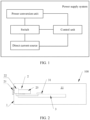
- the power supply system includes a control unit, a switch, a direct current source, and a power conversion unit.
- the switch is electrically connected between the direct current source and the power conversion unit, and the control unit is configured to send a switch-off signal to the switch when a fault occurs on the direct current source or the power conversion unit.
- the direct current source may be a photovoltaic module, a photovoltaic string, or a series-parallel circuit formed by a photovoltaic module and a photovoltaic string, or the direct current source may be a power conversion unit.
- the power conversion unit may be a DC/DC converter or a DC/AC converter.
- Both the direct current source and the power conversion unit may be considered as power supply circuits.
- the control unit detects an occurrence of the fault, and the control unit can send a switch-off signal to the switch. This switch-off signal is used to trigger (that is, drive) the switch to be switched off and disconnect the circuit.
- control unit may be an independent controller.
- the controller is disposed in the power supply system independently of the direct current source and the power conversion unit, and is electrically connected to the power conversion unit, the direct current source, and the switch by using a signal cable.
- the power conversion unit may be an independent power conversion apparatus, for example, an inverter.
- the control unit may be alternatively integrated into another functional apparatus.
- the control unit may be integrated into an inverter, and may be a control circuit or a control chip on a main board in the inverter. In this way, as an independent apparatus, the power conversion apparatus can have a trip-free function in any scenario, that is, can perform automatic tripping in case of a circuit fault.
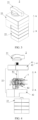
- a power conversion apparatus 100 includes a housing 1, a switch 2, and a circuit board 3.
- the housing 1 surrounds accommodation space 11, the circuit board 3 is disposed in the accommodation space 11, the switch 2 includes a knob 21, a trip-free structure 22, and a contact component 23, the contact component 23 and the trip-free structure 22 are located in the accommodation space 11 and are electrically connected to the circuit board 3, and the knob 21 is located on one side of an outer surface of the housing 1.
- a control unit 31 is disposed on the circuit board 3, the control unit 31 is electrically connected to the trip-free structure 22, and the control unit 31 is configured to send a switch-off signal to the trip-free structure 22, so that the trip-free structure 22 can drive the contact component 23 to be switched off.
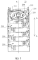
- FIG. 3 is a three-dimensional schematic diagram of a switch 2 according to an embodiment of this application.
- FIG. 4 is an exploded diagram of the switch 2 according to an embodiment of this application.
- the switch 2 includes a knob 21, a trip-free structure 22, and a contact component 23.
- the trip-free structure 22 is disposed in a stacked manner between the knob 21 and the contact component 23 in a first direction A.
- the trip-free structure 22 includes a cover body 4 and a connecting rod mechanism 5 accommodated in the cover body 4.
- the cover body 4 includes an upper cover 41 and a lower cover 42.
- the upper cover 41 and the lower cover 42 are buckled with each other and jointly surround the connecting rod mechanism 5.
- the connecting rod mechanism 5 includes a knob rotating shaft S1 and a contact rotating shaft S2.
- the knob rotating shaft extends out of the cover body 4 from the upper cover 41, the knob rotating shaft S1 is configured to fixedly connect to the knob 21, the knob rotating shaft S1 can be rotated relative to the cover body 4, and an axial extension direction of the knob rotating shaft S1 is the first direction A.
- the contact rotating shaft S2 extends out of the cover body 4 from the lower cover 42, the contact rotating shaft S2 is configured to fixedly connect to the contact component 23, and an extension direction of a rotation center of the contact rotating shaft S2 is the first direction A.
- the trip-free structure 22 and the contact component 23 are accommodated in the housing 1.
- a surface that is of the trip-free structure 22 and that faces away from the contact component 23 may be in contact with an inner surface of the housing 1.
- a through hole is disposed on the housing 1, the knob rotating shaft S1 on the trip-free structure 22 extends out of the through hole, and the knob 21 is mounted on the knob rotating shaft S1 from one side of an outer surface of the housing 1.
- the extension directions of the contact rotating shaft S2 and the knob rotating shaft S1 are defined to be the same, the knob is rotated to drive the contact rotating shaft to be rotated, and a rotation direction of the knob and a rotation direction of the contact rotating shaft may be designed to be the same. Because a moving contact is inside the apparatus, the moving contact cannot be observed with naked eyes. In this application, in a process of operating the knob rotating shaft, a rotation direction of the moving contact can be intuitively learned by using the knob, thereby bringing better use experience. In addition, force is transferred between the knob and the moving contact by using a connecting rod structure, and therefore the structure is simple and ingenious and is easy to maintain.
- the knob 21 includes a handle 211 and a seat body 212.
- the seat body 212 is configured to connect the trip-free structure 22 and the knob rotating shaft S1.
- the handle 211 is connected to one side that is of the seat body 212 and that faces away from the cover body 4 of the trip-free structure 22.
- the handle 211 is used by a user to perform a manual operation, and is configured to indicate statuses of the switch (a switch-on state, a switch-off state, and a fault state). As shown in FIG.
- a mounting hole 213 is disposed on a surface that is of the seat body 212 and that faces the trip-free structure 22, and the knob rotating shaft S1 of the trip-free structure 22 extends out of the housing of the power conversion apparatus and is fastened to the mounting hole 213.
- the mounting hole 213 is located at a central location of the seat body 212.
- the seat body 212 may be flat cylindrical.
- the first direction A is at an axial direction of the seat body 212.
- the handle 211 extends in a strip shape in a radial direction of the seat body 212 and extends out of an outer edge of the seat body 212.
- the central location of the seat body 212 is a circle center, an included angle between a radial direction of the first location P1 and a radial direction of the second location P2 is 90 degrees, and the third location P3 is between the first location P1 and the second location P2.
- the rotation angle of the knob 21 in an embodiment, in a manual switch-on or switch-off process of the switch, the rotation angle of the knob 21 is greater than or equal to 50 degrees, and the rotation angle of the knob 21 is large, and therefore a specific switch-on or switch-off location and trip location are easily identified.
- the rotation angle of the knob 21 is 90 degrees, and the rotation angle being 90 degrees complies with a conventional operation habit. In this way, desirable user experience can be provided.
- a rotation angle range of the contact rotating shaft S2 may be greater than or equal to 50 degrees.
- the moving contact 234 is rotated on a plane perpendicular to a central shaft of a movable part of the contact component by using the central shaft as a center, and a rotation angle of the moving contact 234 is greater than or equal to 50 degrees.
- the rotation angle of the moving contact 234 can be limited to a range greater than or equal to 50 degrees, so that the rotation angle of the moving contact 234 is designed to be large, and an arc blowout is easily implemented, thereby ensuring safety of a power supply system. As shown in FIG. 7 and FIG.
- the rotation angle of the moving contact 234 is 90 degrees; and for each contact unit, two fixed contacts 233 exist on a periphery of the moving contact 234, and are distributed 180 degrees around the central shaft of the movable part on a same circumference.
- a most suitable location is a location at which the rotation angle of the moving contact 234 is 90 degrees. The location is at an equal distance or an equal angle from the two fixed contacts 233.
- the rotation angle of the knob 21 is consistent with the rotation angle of the moving contact 234.
- the contact component 23 includes a plurality of contact units 230 disposed in a stacked manner in the first direction A, and the plurality of contact units 230 are sequentially stacked and are spliced together to form a whole.
- the contact unit 230 includes a fixed part 231 and a movable part 232, and the movable part 232 is rotatably connected to the fixed part 231.
- the fixed part 231 is provided with a fixed contact 233
- the movable part 232 is provided with a moving contact 234.
- the movable part 232 has a central shaft X.
- the central shaft X extends in the first direction A.
- the movable part 232 is capable of being rotated by using the central shaft X as a center, to enable the moving contact 234 and the fixed contact 233 to be switched on or switched off.
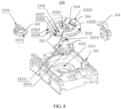
- FIG. 8 is an exploded diagram of a contact unit 230.
- the fixed part 231 can be understood as a square base architecture, and a central through hole 2311 is disposed at a central location of the fixed part 231.
- the fixed contact 233 is mounted at an edge location of the fixed part 231.
- the fixed contact 233 may be fastened to the fixed part 231 specifically in a fastening manner such as fastening using a buckle or a screw.
- the fixed contact 233 includes an inner connecting part 2331 facing the central through hole 2311 and an outer connecting part 2332 located between an outer edge of the fixed part 231 and the inner connecting part 2331.
- the inner connecting part 2331 is of a sheet-like structure, and the inner connecting part 2331 is configured to fit in with the moving contact 234 to implement a circuit connection.
- the outer connecting part 2332 is configured to electrically connect to a circuit board of the power conversion apparatus. Specifically, the outer connecting part 2332 is configured to connect to an electric wire, one end of the electric wire is electrically connected to the outer connecting part 2332, and the other end of the electric wire is electrically connected to the circuit board.
- the movable part 232 is rotatably connected to a location of the central through hole 2311 of the fixed part 231.
- the movable part 232 includes a first rotating member 2321 and a second rotating member 2322.
- the first rotating member 2321 includes a base 23211 and a rotating shaft structure 23212.
- the movable part 232 is of a centrosymmetric structure, and the central shaft of the movable part 232 is a central shaft of the rotating shaft structure 23212.
- the rotating shaft structure 23212 is fixedly connected to the base 23211 and is disposed in a protruding manner from a surface of the base 23211.
- the base 23211 is configured to fit in with the central through hole 2311 of the fixed part 231, and the base 23211 is rotatably connected to the fixed part 231.
- the base 23211 is rotatably mounted in the central through hole 2311 and can be rotated in the central through hole 2311 by using the central shaft of the movable part 232 as a rotation center.
- a direction in which the rotating shaft structure 23212 protrudes and extends is the first direction, and an extension direction of the central shaft of the movable part 232 is also the first direction.
- a rotating shaft structure 23212 in a contact unit 230 adjacent to the trip-free structure 22 is configured to fixedly connect to the contact rotating shaft S2 of the trip-free structure 22, and a rotating shaft structure 23212 of another contact unit 230 is configured to fixedly connect to a base 23211 of an adjacent contact unit 230.
- a fastening hole 23213 is disposed on the rotating shaft structure 23212, the fastening hole 23213 is formed by being recessed from an end face that is of the rotating shaft structure 23212 and that faces away from the base 23211, and the fastening hole 23213 is configured to fit in with the contact rotating shaft S2 of the trip-free structure 22. As shown in FIG.
- a fastening hole 23214 is disposed on the base 23211, the fastening hole 23214 of the base 23211 is formed by being recessed from an end face that is of the base 23211 and that faces away from the rotating shaft structure 23212, and the rotating shaft structure 23212 is inserted into the fastening hole 23214 of the base 23211, to implement a fixed connection between movable parts 232 of the two adjacent contact units 230.
- the second rotating member 2322 is fixedly connected to the first rotating member 2321.
- a fastening through hole 23221 is disposed at a central location of the second rotating member 2322, and the second rotating member 2322 is sleeved on the rotating shaft structure 23212 of the first rotating member 2321.
- the fixed connection between the first rotating member 2321 and the second rotating member 2322 is implemented by making the fastening through hole 23221 fit in with the rotating shaft structure 23212.
- the fastening through hole 23221 is square-shaped, and the rotating shaft structure 23212 is square columnar.
- the second rotating member 2322 is of a disk-like structure, the second rotating member 2322 includes an intermediate region 23222 and an edge region 23223, the edge region 23223 is disposed around a periphery of the intermediate region 23222, and the fastening through hole 23221 is located at the center of the intermediate region 23222.
- the intermediate region 23222 is of a plate-shaped structure, the edge region 23223 includes a first plate 23224 and a second plate 23225 spaced from each other, and a gap is formed between the first plate 23224 and the second plate 23225. In an axial direction (the first direction) of the second rotating member 2322, the first plate 23224 and the second plate 23225 are stacked and spaced from each other.
- the intermediate region 23222 faces a middle location of the gap between the first plate 23224 and the second plate 23225.
- a first notch 23226 is disposed on the first plate 23224, and a second notch 23227 is disposed on the second plate 23225.
- the first notch 23226 faces the second notch 23227 in the axial direction of the second rotating member 2322.
- the moving contact 234 is fixedly connected to a surface of the intermediate region 23222, and a part of the moving contact 234 extends into the first notch 23226 and the second notch 23227.
- the moving contact 234 includes an assembling part 2341 and a fitting part 2342.
- the assembling part 2341 is fixedly connected to the intermediate region 23222 of the second rotating member 2322.
- the fitting part 2342 is configured to fit in with or separate from the inner connecting part 2331 of the fixed contact 233 to implement switch-on or switch-off.
- the fitting part 2342 has an architecture with a pair of clamping pieces for clamping the inner connecting part 2331.
- the pair of clamping pieces extend into locations of the first plate 23224 and the second plate 23225 from locations of and the second notch 23227 and the first notch 23226, respectively.
- the fitting part 2342 has elastic deformation, and clamps the inner connecting part 2331 of the fixed contact 233 by elastic force.
- the inner connecting part of the fixed contact 233 extends into the gap between the first plate 23224 and the second plate 23225.
- the fitting part 2342 clamps the inner connecting part 2331 of the fixed contact 233, and the fitting part 2342 and the inner connecting part 2331 form an electrical connection.
- This state is a switch-on state of the switch. As shown in FIG.
- This state may be a switch-off state of the switch.
- the cover body 4 of the trip-free structure 22 is internally provided with the connecting rod mechanism.
- the upper cover 41 and the lower cover 42 of the cover body 4 are buckled with each other.
- the upper cover 41 may be fixedly connected to the lower cover 42 by using a fastener, or the upper cover 41 may be fixedly connected to the lower cover 42 by using an adhesive.
- the knob rotating shaft S1 of the connecting rod mechanism 5 extends out of the cover body 4 from the upper cover 41, and the contact rotating shaft S2 of the connecting rod mechanism 5 extends out of the cover body 4 from the lower cover 42.
- the contact rotating shaft S2 is configured to fixedly connect to the movable part 232 of the contact component 23, which can also be understood as follows:
- the contact rotating shaft S2 is fixedly connected to the moving contact 234. In this way, a rotation process of the contact rotating shaft S2 can drive the moving contact 234 to be rotated around the central shaft X of the contact component 23 (referring to FIG. 7 ).
- FIG. 14 is a three-dimensional diagram of the connecting rod mechanism 5, and FIG. 15 and FIG. 16 are two three-dimensional exploded diagrams of the connecting rod mechanism 5.
- the connecting rod mechanism 5 includes a trip unit 51 and a transmission structure 52.
- the trip unit 51 is electrically connected to a control unit in the power supply system, and is configured to receive a switch-off signal sent by the control unit.
- the trip unit 51 is buckled with or unlocked from the transmission structure 52.
- the trip unit 51 can be unlocked from the transmission structure 52, so that the switch is switched to a tripping state and the switch implements automatic circuit opening in a fault state, that is, implements a trip-free function.
- the trip unit 51 includes an electromagnet 511 and a latch 512.
- a connecting piece (for example, a connecting piece similar to the connecting rod structure 522 or a gear transmission structure) may be disposed between the electromagnet 511 and the latch 512.
- the electromagnet 511 drives the latch 512 to move, and the latch 512 is configured to be buckled with or unlocked from the transmission structure 52.
- the switch-off signal sent by the control unit to the trip unit 51 is an electrical signal, and is used to drive the electromagnet 511 to work, thereby driving the latch 512 to move.
- a buckle hole 5122 is disposed on the latch 512, and the buckle hole 5122 is configured to be buckled with a buckle structure on the transmission structure 52.
- the knob may be operated to implement re-buckling between the trip unit 51 and the transmission structure 52, that is, the knob may be manually operated to drive the transmission structure 52 to move to be buckled with the trip unit 51.
- the knob by rotating the knob, a re-buckling action after trip free is completed.
- the knob is used for manual switch-on or switch-off and can also be used for a re-buckling process, and no other driving structure needs to be disposed in the switch to drive re-buckling between a cradle and the trip unit. This is conducive to ensuring a compact structure and a miniaturized volume of the switch.
- an automatic control apparatus may be alternatively disposed to implement re-buckling.
- an electromagnet 511 used for switch-on is disposed to drive the transmission structure 52 to move to be buckled with the trip unit 51.
- the transmission structure 52 includes the knob rotating shaft S1, the transmission member 521, the connecting rod structure 522, the cradle 523, an elastic member 524, and the contact rotating shaft S2.
- the cradle 523 includes the buckle structure 5232, and the buckle structure 5232 is configured to be buckled with the buckle hole 5122.
- the connecting rod structure 522 is connected between the cradle 523 and the contact rotating shaft S2, and the contact rotating shaft S2 is fixedly connected to the movable part 232 of the contact component 23.
- the trip-free structure 22 includes a mounting bracket 221 and the mounting plate 222, the mounting bracket 221 is disposed in a stacked manner between the contact component 23 and the mounting plate 222 in the first direction, the mounting bracket 221 is configured to assemble the transmission member 521, the cradle 523, the connecting rod structure 522, and the contact rotating shaft S2, and the mounting plate 222 is configured to assemble the knob rotating shaft S1.
- the knob rotating shaft S1 and the contact rotating shaft S2 are disposed on the mounting plate 222 and the mounting bracket 221, respectively.
- the knob rotating shaft S1 is connected to the transmission member 521 by using a connection structure, and the transmission member 521 drives the connecting rod structure 522 to move.
- the trip unit 51 can drive the cradle 523 to drive the connecting rod structure 522 to move, and drive the moving contact 234 and the fixed contact 233 to separate from each other.
- the transmission member 521 and the mounting bracket 221 are connected to a location of a transmission rotating shaft S3, the knob rotating shaft S1 is rotatably connected to the mounting plate 222, and the knob 21 is fastened to the knob rotating shaft S1 and is located on one side that is of the mounting plate 222 and that is away from the mounting bracket 221.
- the transmission structure 52 further includes the connecting rod mechanism 525.
- the connecting rod mechanism 525 is also referred to as a connection unit.
- the connection unit is connected between the knob rotating shaft S1 and the transmission member 521 to transfer force.
- the connecting rod mechanism 525 is fixedly connected to the knob rotating shaft S 1.
- the connecting rod mechanism 525 fits in with the transmission member 521, so that in a rotation process of the knob 21, the connecting rod mechanism 525 is capable of driving the transmission member 521 to swing by using the transmission rotating shaft S3 as a center.
- the transmission member 521 includes swing arms 5211 and a connecting arm 5212, a part of the swing arm 5211 is disposed in a stacked manner between the mounting bracket 221 and the mounting plate 222 in the first direction, and the swing arms 5211 fit in with the connecting rod mechanism 525 so that the connecting rod mechanism 525 is capable of driving the transmission member 521 to move.
- the first arm 11A is disposed in a stacked manner between the mounting bracket 221 and the mounting plate 222 in the first direction.
- the second arm 11B is disposed in a stacked manner in the first direction on one side that is of the mounting bracket 221 and that is away from the mounting plate 222.
- the first arm 11A and the second arm 11B are located on a top surface and a bottom surface of the mounting bracket 221, respectively.
- the connecting arm 5212 is bent relative to the swing arms 5211, and the connecting arm 5212 is located on one side edge of the mounting bracket 221 (the side edge of the mounting bracket 221 can be understood as a portion connected between the top surface and the bottom surface).
- Accommodation space G is enclosed by the mounting bracket 221.
- the mounting bracket 221 includes a bottom plate 2211 and a top plate 2212 that are disposed opposite to each other, the bottom plate 2211 and the top plate 2212 are stacked and spaced from each other in the first direction, and the accommodation space G is formed between the bottom plate 2211 and the top plate 2212.
- the cradle 523 and the connecting rod structure 522 are disposed in the accommodation space G and are rotatably connected to the mounting bracket 221.
- the electromagnet 511 of the trip unit 51 is mounted on the bottom plate 2211 and is located on one side that is of the bottom plate 2211 and that is away from the top plate 2212, and the latch 512 of the trip unit 51 is located between the bottom plate 2211 and the top plate 2212.
- the contact rotating shaft S2 is rotatably connected to the mounting bracket 221 and extends out of the accommodation space G from the side that is of the bottom plate 2211 and that is away from the top plate 2212, and the knob rotating shaft S2 is located on one side that is of the top plate 2212 and that is away from the bottom plate 2211.
- At least a part of the connecting arm 5212 faces the accommodation space G, one end of the elastic member 524 is fixedly connected to the connecting arm 5212, and the other end of the elastic member 524 extends into the accommodation space G and is connected to the connecting rod structure 522.
- the connecting arm 5212 is connected between the first arm 11A and the second arm 11B, one end of the connecting arm 5212 is connected to an edge of the first arm 11A, and the other end of the connecting arm 5212 is connected to an edge of the second arm 11B.
- the mounting bracket 221 and an edge location that is of the first arm 11A and that is away from the connecting arm 5212 are rotatably connected to a location of the transmission rotating shaft S3, and the mounting bracket 221 and an edge location that is of the second arm 11B and that is away from the connecting arm are rotatably connected to a location of the transmission rotating shaft S3, which can be understood as follows:
- a rotating shaft rotatably connected between the first arm 11A and the mounting bracket 221 and a rotating shaft rotatably connected between the second arm 11B and the mounting bracket 221 are coaxial and are both the transmission rotating shaft S3.
- fitting space 11G for accommodating a part of the connecting rod mechanism 525 is disposed on the first arm 11A of the swing arms 5211, the part of the connecting rod mechanism 525 is located in the fitting space 11G and can move in the fitting space 11G, and the connecting rod mechanism 525 abuts against an inner surface of the fitting space 11G, so that the connecting rod mechanism 525 drives the transmission member 521 to swing around the transmission rotating shaft S3.
- the first arm 11A includes a plate-shaped main body 11A1 and a pair of limiting blocks 11A2 disposed in a protruding manner on a surface of the plate-shaped main body 11A1, and a region between the pair of limiting blocks 11A2 is the fitting space 11G.
- the first arm 11A includes a plate-shaped main body 11A1 and a limiting clamp 11A3.
- the limiting clamp 11A3 is U-shaped, and the limiting clamp 11A3 includes a pair of limiting blocks 11A2 and a connecting block 11A4.
- the connecting block 11A4 is connected between the pair of limiting blocks 11A2.
- a pair of through holes are disposed on the plate-shaped main body 11A1, and the pair of limiting blocks 11A2 respectively pass through the pair of through holes.
- the connecting block 11A4 is fastened to the plate-shaped main body 11A1 by using a fastener, for example, by using a screw.
- the connecting block 11A4 is located on a bottom surface of the plate-shaped main body 11A1.
- the pair of limiting blocks 11A2 protrude from a top surface of the plate-shaped main body 11A1 after passing through the through holes, and form the fitting space 11G on the top surface of the plate-shaped main body 11A1.
- the connecting rod mechanism 525 includes a first end 5251 and a second end 5252, the first end 5251 is fixedly connected to the knob rotating shaft S1, and the second end 5252 fits in with the transmission member 521.
- the second end 5252 moves circumferentially by using a central shaft of the knob rotating shaft S1 as a center.
- the connecting rod mechanism 525 is configured to: in the rotation process of the knob rotating shaft S1, apply driving force in a circumferential direction to the transmission member 521, and drive the transmission member 521 to swing around the transmission rotating shaft S3.
- the connecting rod mechanism 525 includes a main body part 5253 and a fitting part 5254, the main body part 5253 is of an integral structure and is strip-shaped sheet-like or rod-like, and the first end 5251 and the second end 5252 of the connecting rod mechanism 525 are two opposite ends of the main body part 5253.
- the fitting part 5254 is rotatably connected to the main body part 5253, an outer surface of a part that is of the fitting part 5254 and that extends into the fitting space 11G may be a cylindrical surface or an arc surface, and the fitting part 5254 may be of a flat cylindrical structure or a spherical structure.
- a rotating connection structure between the fitting part 5254 and the main body part 5253 facilitates a smoother process in which the knob rotating shaft S 1 is rotated to drive the fitting part 5254 of the connecting rod mechanism 525 to move in the fitting space 11G, and no jam situation occurs. It can be learnt from FIG. 20 that, in a state in which one side of the fitting part 5254 is in contact with the inner surface of the fitting space 11G, a gap is disposed between the other side of the fitting part 5254 and the inner surface of the fitting space 11G. Disposing the gap can ensure that a location of the fitting part 5254 is not limited or interfered with by the limiting blocks 11A2 in a process in which the connecting rod mechanism 525 drives the transmission member 521 to swing.
- arc-shaped sliding space is enclosed by the limiting blocks 11A2, it means that the fitting part 5254 needs to slide along the arc-shaped sliding space. This imposes a requirement on precision and difficulty control for a designer, and a high requirement on assembly tolerance fitting in an assembly process. Therefore, in this application, a design in which the fitting part 5254 can move in the fitting space 11G is used, to reduce design difficulty and precision requirements, reduce a requirement on assembly precision, and reduce fabrication costs.
- a sliding slot 11A5 may be disposed on the first arm 11A of the swing arms 5211, and an area in the sliding slot 11A5 is the fitting space 11G.
- the fitting part 5254 of the connecting rod mechanism 525 is mounted in the sliding slot 11A5, and a size of the fitting part 5254 is less than space in the sliding slot 11A5, so that the fitting part 5254 can move in the sliding slot 11A5.
- the fitting part 5254 abuts against an inner wall of the sliding slot 11A5, so that the connecting rod mechanism 525 can drive the transmission member 521 to swing.
- the sliding slot 11A5 may be in a shape of a through hole or a blind hole.
- connection unit connected between the transmission member 521 and the knob rotating shaft S1 is of a connecting rod mechanism-type structure, and the main body part of the connection unit is of an integral sheet-like or rod-like structure.
- connection unit connected between the transmission member 521 and the knob rotating shaft S1 uses a gear transmission solution.
- a connection unit 525' includes a main body part 5255 and a fitting part 5258.
- the main body part 5255 includes a driving gear 5256 and a transmission gear 5257, the driving gear 5256 is fixedly connected to the knob S1, the transmission gear 5257 is rotatably connected to the mounting plate 222 at a location of a rotating shaft 52571, the transmission gear 5257 meshes with the driving gear 5256, a periphery of the transmission gear 5257 includes a transmission arm 5259, the transmission arm 5259 is connected to the fitting part 5258, the fitting part 5258 is located in the fitting space 11G, and the fitting part 5258 abuts against the inner surface of the fitting space 11G, so that the connection unit 525' drives the transmission member 521 to move.
- the fitting part 5258 is rotatably connected to the transmission arm 5259, that is, the fitting part 5258 can be rotated freely relative to the transmission arm 5259 by using a fixed rotating shaft as a center.
- the first arm 11A of the swing arms 5211 in the transmission member 521 is rotatably connected to the top plate 2212 of the mounting bracket 221 at the location of the transmission rotating shaft S3
- the second arm 11B of the swing arms 5211 in the transmission member 521 is rotatably connected to the bottom plate 2211 at the location of the transmission rotating shaft S3.
- the latch 512 of the trip unit 51 is rotatably connected to the mounting bracket 221 by using a rotating shaft, and the latch 512 is located between the top plate 2212 and the bottom plate 2211 and is rotatably connected to edge locations of the top plate 2212 and the bottom plate 2211.
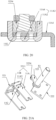
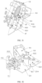
- FIG. 24 to FIG. 30 can clearly show specific forms of the cradle 523 and the connecting rod structure 522 and a specific connection relationship between the cradle 523 and the connecting rod structure 522.
- FIG. 25 and FIG. 26 are exploded diagrams of a structure shown in FIG. 24 in two directions.
- FIG. 27 and FIG. 28 are two three-dimensional diagrams of the cradle 523 and the connecting rod structure 522 in an assembled state.
- FIG. 29 and FIG. 30 are exploded diagrams of the cradle 523 and the connecting rod structure 522 in two directions.
- the cradle 523 includes a first transfer plate 5231, a second transfer plate 5233, and a connecting plate 5234 connected between the two transfer plates.
- the first transfer plate 5231 and the second transfer plate 5233 are disposed opposite to each other, and assembly space 5235 is formed between the two transfer plates. This assembly space 5235 is configured to accommodate the connecting rod structure 522.
- the connecting plate 5234 is connected between an edge of the first transfer plate 5231 and an edge of the second transfer plate 5233.
- the first transfer plate 5231 and the second transfer plate 5233 have a same structural form.
- the first transfer plate 5231 is rotatably connected to the bottom plate 2211 of the mounting bracket 221 by using a cradle rotating shaft S4
- the second transfer plate 5233 is rotatably connected to the top plate 2212 of the mounting bracket 221 by using a cradle rotating shaft S4.
- the cradle rotating shaft S4 on the bottom plate 2211 and the cradle rotating shaft S4 on the top plate 2212 are collinear (coaxially disposed). In a process in which the cradle 523 is rotated relative to the mounting bracket 221, the cradle 523 is rotated by using the cradle rotating shaft S4 as a center.
- a switch-on limiting structure 5236 is disposed on the cradle rotating shaft S4.
- the switch-on limiting structure 5236 is configured to abut against the connecting rod structure 522.
- the connecting rod structure 522 is in contact with the switch-on limiting structure 5236, to restrict the movement of the connecting rod structure 522, thereby limiting the moving contact 234 to be in the manual switch-on state.
- the cradle rotating shaft S4 is disposed on the mounting bracket 221, in the manual switch-on or switch-off process, the cradle 523 and the mounting bracket 221 are relatively stationary, that is, the cradle rotating shaft and the mounting bracket 221 are relatively fixed. It can be understood that the switch-on limiting structure 5236 provided in this embodiment of this application is disposed on the mounting bracket 221.
- a groove 5237 is disposed on the edge of the first transfer plate 5231, and a groove 5237 is disposed on the edge of the second transfer plate 5233.
- the two grooves 5237 have a same structural form, and the two grooves 5237 are disposed opposite to each other in an axial direction of the cradle rotating shaft S4.
- the axial direction of the cradle rotating shaft S4 can be understood as a direction of a vertical connection line between the first transfer plate 5231 and the second transfer plate 5233.
- the groove 5237 of the cradle 523 is configured to fit in with the connecting rod structure 522 to limit the connecting rod structure 522 when the switch is in a manual switch-off state, that is, limit a specific location of the moving contact 234.
- the first transfer plate 5231 is in contact with the bottom plate 2211 of the mounting bracket 221, and the second transfer plate 5233 is in contact with the top plate 2212 of the mounting bracket 221, so that the cradle 523 is stably connected between the bottom plate 2211 and the top plate 2212.
- the first transfer plate 5231 is attached to the bottom plate 2211 and slides along a surface of the bottom plate 2211
- the second transfer plate 5233 is attached to the top plate 2212 and slides along a surface of the top plate 2212. This can ensure stability of movement of the cradle 523 and stability of connections and the movement of the connecting rod structure 522 in a tripping process of the switch.
- the connecting plate 5234 of the cradle 523 includes a plate body 52341 and a buckle structure 5232 that is bent and extends from an edge of the plate body 52341.
- the plate body 52341 is configured to connect the first transfer plate 5231 and the second transfer plate 5233.
- a bending direction of the buckle structure 5232 is opposite to a bending direction of the first transfer plate 5231.
- the connecting rod structure 522 is located between the first transfer plate 5231 and the second transfer plate 5233, and the connecting rod structure 522 and the buckle structure 5232 are respectively located on two sides of the plate body 52341.
- the buckle structure 5232 is configured to fit in with the buckle hole 5122 of the latch 512 of the trip unit 51 to implement fitting (buckling) between the cradle 523 and the trip unit 51.
- the cradle 523 drives the connecting rod structure 522 to move, to separate the moving contact 234 from the fixed contact 233.
- a linkage path between the trip unit 51 and the moving contact 234 is that the cradle 523 drives the connecting rod structure 522 to move and the connecting rod structure 522 drives the moving contact 234 to move, and the knob rotating shaft is completely free of this linkage path.
- the connecting rod structure 522 includes an upper connecting rod 5221, a lower connecting rod 5222, and a main shaft 5223.
- One end of the upper connecting rod 5221 is rotatably connected to the cradle 523, the other end of the upper connecting rod 5221 is rotatably connected to one end of the lower connecting rod 5222 by using a first rotating shaft S5, and the other end of the lower connecting rod 5222 is rotatably connected to one end of the main shaft 5223.
- the upper connecting rod 5221 and the cradle 523 are rotatably connected to a location of a second rotating shaft S6, the second rotating shaft S6 is fixedly connected to the cradle 523, and the upper connecting rod 5221 can swing by using the second rotating shaft S6 as a fulcrum.
- the first rotating shaft S5 between the upper connecting rod 5221 and the lower connecting rod 5222 is in a free state relative to the mounting bracket 221 and the cradle 523. In other words, there is no connection relationship between the first rotating shaft S5 and the mounting bracket 221 or between the first rotating shaft S5 and the cradle 523.
- the lower connecting rod 5222 is rotatably connected to the main shaft 5223 by using a third rotating shaft S7.
- the third rotating shaft S7 is in a free state relative to the mounting bracket 221 and the cradle 523. In other words, there is no connection relationship between the third rotating shaft S7 and the mounting bracket 221 or between the third rotating shaft S7 and the cradle 523.
- a center of the second rotating shaft S6, a center of the cradle rotating shaft S4, and any point on the buckle structure 5232 form an acute triangle.
- the cradle 523 with a small size can be obtained. Disposing an internal structure of the switch in small space is conducive to miniaturization of the switch.
- the first rotating shaft S5 is configured to connect the elastic member 524.
- one end of the elastic member 524 is fastened at a location of the first rotating shaft S5, and the other end of the elastic member 524 is fastened to the transmission member 521. In this way, movement of the transmission member 521 can drive the connecting rod structure 522 to move.
- the main shaft 5223 is fixedly connected to the contact rotating shaft S2, and the two shafts may be of an integral structure. It can also be understood that the main shaft 5223 is fixedly connected to the moving contact 234, and the main shaft 5223 can be rotated relative to the mounting bracket 221, to drive the moving contact 234 to be rotated.
- limiting blocks S21 are disposed in a protruding manner on a periphery of the contact rotating shaft S2, or it can be understood that the limiting blocks S21 are fixedly connected to the main shaft 5223.
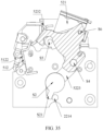
- a trip limiting structure 2214 is disposed on the mounting bracket 221.
- the limiting blocks S21 abut against the trip limiting structure 2214 in a process in which the trip unit 51 drives the moving contact 234 and the fixed contact 233 to separate from each other, to limit the contact rotating shaft S2, so that the moving contact 234 is in a still state in a re-buckling process.
- an electric arc caused by movement of the moving contact 234 in the re-buckling process can be avoided.
- two fixed contacts 233 in a contact unit are distributed 180 degrees around a circumference on a periphery of the central shaft, and a location at which a rotation angle of the moving contact 234 is 90 degrees is an optimal location of the moving contact 234 in a switch-off state.
- a location of the moving contact 234 is designed to be rotated by 90 degrees. In this state, the moving contact 234 is farthest from the fixed contacts 233. This avoids the movement of the moving contact 234 in the re-buckling process, and avoids an occurrence of a particular rotation phenomenon of the moving contact 234, thereby avoiding an occurrence of an electric arc.
- manual switch-on or switch-off of the switch can be implemented by rotating the knob.
- the buckle structure 5232 of the cradle 523 always keeps fitting in with the buckle hole 5122 of the latch 512 of the trip unit 51 in manual switch-on and manual switch-off processes.
- the knob drives the knob rotating shaft S1 to be rotated, and the knob rotating shaft S1 drives, by using the connecting rod mechanism 525, the transmission member 521 to swing by using the transmission rotating shaft S3 as a fulcrum.
- Elastic deformation occurs on the elastic member 524 in a swinging process of the transmission member 521.
- Elastic force of the elastic member 524 drives the connecting rod structure 522 to move, and the main shaft 5223 of the connecting rod structure 522 drives the contact rotating shaft S2 to be rotated. In this way, the moving contact 234 is rotated, so that the moving contact 234 is separated from the fixed contact 233. As shown in FIG. 33 , the moving contact 234 is limited to be in the manual switch-off state by contact limiting between the first rotating shaft S5 of the connecting rod structure 522 and an inner wall of the groove 5237 of the cradle 523.
- an included angle A1 between an elastic force direction of the elastic member 524 and the upper connecting rod 5221 is greater than or equal to 30 degrees and less than or equal to 45 degrees.
- the elastic force direction of the elastic member 524 is a direction of a connection line between two ends of the elastic member 524
- an extension direction of the upper connecting rod 5221 is a direction of a connection line between a central location of a rotating shaft (namely, the second rotating shaft S6) between the upper connecting rod 5221 and the cradle 523 and a central location of the rotating shaft (namely, the first rotating shaft S5) between the lower connecting rod 5222 and the upper connecting rod 5221.
- large switch-off force can be achieved by limiting a range of the included angle between the elastic force direction of the elastic member 524 and the upper connecting rod 5221 in the manual switch-off state.
- a larger included angle A1 between the elastic member 524 and the upper connecting rod 5221 leads to larger switch-off force.
- the included angle A1 between the elastic force direction of the elastic member 524 and the upper connecting rod 5221 may be limited to be greater than or equal to 35 degrees and less than or equal to 40 degrees.
- the manual switch-on process is as follows: The knob is rotated to enable the knob rotating shaft to be rotated, and the connecting rod mechanism 525 drives the transmission member to swing by using the transmission rotating shaft S3 as a fulcrum.
- the elastic deformation occurs on the elastic member 524 in the swinging process of the transmission member.
- the elastic force of the elastic member 524 drives the connecting rod structure 522 to move, and the main shaft of the connecting rod structure 522 drives the contact rotating shaft S2 to be rotated.
- the moving contact 234 moves to be in contact with the fixed contact 233.
- a state in which the moving contact 234 is in contact with the fixed contact 233 is the manual switch-on state. As shown in FIG.
- an included angle A2 between the lower connecting rod 5222 and the upper connecting rod 5221 of the connecting rod structure 522 is greater than or equal to 170 degrees and less than 180 degrees.
- the connecting rod structure 522 can quickly drive the moving contact 234 to move, and if the included angle A2 between the upper connecting rod 5221 and the lower connecting rod 5222 is closer to 180 degrees, a speed of driving the moving contact 234 and the fixed contact 233 to be switched off is faster.
- the included angle A2 between the upper connecting rod 5221 and the lower connecting rod 5222 cannot be equal to 180 degrees.
- a location at which the included angle A2 between the upper connecting rod 5221 and the lower connecting rod 5222 is 180 degrees is a dead spot location.
- the range of the included angle A2 between the upper connecting rod 5221 and the lower connecting rod 5222 is set to be from 170 degrees to 178 degrees in consideration of factors such as a design error, a fabrication process tolerance, and an error in an assembly process. In an embodiment, the range of the included angle A2 between the upper connecting rod 5221 and the lower connecting rod 5222 is from 175 degrees to 178 degrees. This can improve a switch-off function of the switch.
- the trip unit 51 receives a switch-off signal in this embodiment of this application, and the latch 512 of the trip unit 51 moves, so that the buckle structure 5232 of the cradle 523 is separated from the buckle hole 5122 of the latch 512.
- the cradle 523 is no longer restricted by the trip unit 51, and the cradle 523 is automatically rotated by using the cradle rotating shaft S4 as a center.
- the cradle 523 drives the connecting rod structure 522 to move, and the connecting rod structure 522 drives the contact rotating shaft S2 to be rotated, to drive the moving contact to move, so that the moving contact 234 is separated from the fixed contact 233, thereby implementing free cradling.
- the connecting rod structure 522 drives the contact rotating shaft S2 to be rotated, to drive the moving contact to move, so that the moving contact 234 is separated from the fixed contact 233, thereby implementing free cradling.
- the cradle 523 directly drives the connecting rod structure 522 to move and only the connecting rod structure 522 exists on a transmission path from the cradle 523 to the contact rotating shaft S2. Therefore, even if the knob is stuck and cannot move, the switch can implement free cradling.
- the contact rotating shaft S2 In a free cradling state, the contact rotating shaft S2 is restricted by contact between the trip limiting structure 2214 and the limiting blocks S21 on the contact rotating shaft S2, so that the moving contact 234 is in a still state in the re-buckling process.
- the knob in the switch provided in this application may be used for manual switch-off and manual switch-on operations, and the knob drives the connecting rod structure to move to implement manual switch-on or switch-off.
- the switch provided in this application has a trip-free function, and through unlocking of the trip unit from the cradle (removal of a buckling relationship between the buckle structure and the buckle hole), the cradle can drive the connecting rod structure to move, and the connecting rod structure drives the moving contact to move, thereby implementing switch-off. Because the knob and the transmission member are free of force transfer in a trip-free process, if the knob is blocked by a cable or other components and cannot be rotated in the trip-free process, the switch can still implement trip free.
- the knob can also be used for re-buckling after automatic tripping in a fault state, the knob can be rotated to drive the connecting rod structure to move, and the connecting rod structure drives the cradle to move to be buckled with the trip unit, to complete the re-buckling process.
Landscapes
- Engineering & Computer Science (AREA)
- Power Engineering (AREA)
- Physics & Mathematics (AREA)
- Electromagnetism (AREA)
- Rotary Switch, Piano Key Switch, And Lever Switch (AREA)
- Breakers (AREA)
- Driving Mechanisms And Operating Circuits Of Arc-Extinguishing High-Tension Switches (AREA)
- Keying Circuit Devices (AREA)
Applications Claiming Priority (2)
| Application Number | Priority Date | Filing Date | Title |
|---|---|---|---|
| CN202111212394.3A CN114093732B (zh) | 2021-10-18 | 2021-10-18 | 开关、功率变换装置和供电系统 |
| EP22201779.0A EP4167263B1 (de) | 2021-10-18 | 2022-10-17 | Schalter, leistungsumwandlungsvorrichtung und stromversorgungssystem |
Related Parent Applications (1)
| Application Number | Title | Priority Date | Filing Date |
|---|---|---|---|
| EP22201779.0A Division EP4167263B1 (de) | 2021-10-18 | 2022-10-17 | Schalter, leistungsumwandlungsvorrichtung und stromversorgungssystem |
Publications (2)
| Publication Number | Publication Date |
|---|---|
| EP4451539A2 true EP4451539A2 (de) | 2024-10-23 |
| EP4451539A3 EP4451539A3 (de) | 2025-01-08 |
Family
ID=80297085
Family Applications (2)
| Application Number | Title | Priority Date | Filing Date |
|---|---|---|---|
| EP24171501.0A Pending EP4451539A3 (de) | 2021-10-18 | 2022-10-17 | Schalter, leistungsumwandlungsvorrichtung und stromversorgungssystem |
| EP22201779.0A Active EP4167263B1 (de) | 2021-10-18 | 2022-10-17 | Schalter, leistungsumwandlungsvorrichtung und stromversorgungssystem |
Family Applications After (1)
| Application Number | Title | Priority Date | Filing Date |
|---|---|---|---|
| EP22201779.0A Active EP4167263B1 (de) | 2021-10-18 | 2022-10-17 | Schalter, leistungsumwandlungsvorrichtung und stromversorgungssystem |
Country Status (3)
| Country | Link |
|---|---|
| US (2) | US12340959B2 (de) |
| EP (2) | EP4451539A3 (de) |
| CN (2) | CN114093732B (de) |
Families Citing this family (11)
| Publication number | Priority date | Publication date | Assignee | Title |
|---|---|---|---|---|
| CN113963978B (zh) * | 2020-07-20 | 2023-01-10 | 上海良信电器股份有限公司 | 一种旋转开关 |
| CN114743843B (zh) * | 2022-03-24 | 2024-07-30 | 华为数字能源技术有限公司 | 动力机构、开关、功率变换装置和供电系统 |
| CN114792610A (zh) * | 2022-04-02 | 2022-07-26 | 华为数字能源技术有限公司 | 供电系统及开关单元 |
| CN116960746A (zh) * | 2022-04-15 | 2023-10-27 | 上海良信电器股份有限公司 | 一种隔离开关安装结构及开关柜 |
| EP4297058B1 (de) * | 2022-05-27 | 2025-12-10 | Huawei Digital Power Technologies Co., Ltd. | Stromversorgungssystem und schalteinheit |
| EP4539078A1 (de) * | 2023-01-19 | 2025-04-16 | Shanghai Liangxin Electrical Co., Ltd. | Isolationsschalterkörper, isolationsschalter und stromverteilungssystem |
| CN220359017U (zh) * | 2023-06-30 | 2024-01-16 | 华为数字能源技术有限公司 | 一种逆变器 |
| CN118675929A (zh) * | 2024-05-21 | 2024-09-20 | 华为数字能源技术有限公司 | 一种直流开关以及功率变换器 |
| CN119315494B (zh) * | 2024-07-31 | 2025-12-02 | 华为数字能源技术有限公司 | 逆变器 |
| WO2026026760A1 (zh) * | 2024-07-31 | 2026-02-05 | 华为数字能源技术有限公司 | 逆变器 |
| CN119696389B (zh) * | 2025-01-02 | 2025-10-10 | 浙江科能达智能装备有限公司 | 一种耐用且使用稳定的太阳能逆变器及其使用方法 |
Family Cites Families (12)
| Publication number | Priority date | Publication date | Assignee | Title |
|---|---|---|---|---|
| BE368280A (de) * | 1930-03-05 | |||
| US6087913A (en) * | 1998-11-20 | 2000-07-11 | General Electric Company | Circuit breaker mechanism for a rotary contact system |
| US20020158732A1 (en) * | 2001-04-30 | 2002-10-31 | Castonguay Roger Neil | Electronic trip unit interlock for circuit breakers |
| JP4720059B2 (ja) * | 2001-09-25 | 2011-07-13 | 富士電機機器制御株式会社 | 回路しゃ断器のトリップ表示装置 |
| US8093965B2 (en) * | 2008-12-03 | 2012-01-10 | Schneider Electric USA, Inc. | Add-on trip module for multi-pole circuit breaker |
| KR101492222B1 (ko) * | 2012-10-23 | 2015-02-13 | 임철근 | 누전차단기의 순시트립장치 |
| CN103594292B (zh) * | 2013-10-18 | 2016-05-25 | 上海诺雅克电气有限公司 | 带脱扣类型指示的旋钮式开关电器 |
| FR3029009B1 (fr) * | 2014-11-21 | 2017-01-06 | Socomec Sa | Systeme de commande a declenchement pour pole de coupure et appareil de coupure |
| FR3054925B1 (fr) * | 2016-08-02 | 2020-05-15 | Socomec | Module de commande pour appareil de coupure electrique modulaire et appareil de coupure electrique modulaire obtenu |
| CN112750643B (zh) * | 2019-10-31 | 2025-03-18 | 上海良信电器股份有限公司 | 一种具有远程控制切换功能的旋转开关 |
| CN111863496A (zh) * | 2020-07-20 | 2020-10-30 | 上海良信电器股份有限公司 | 一种储能状态监测结构及旋转开关 |
| CN113053689B (zh) | 2021-03-18 | 2022-09-09 | 浙江奔一电气有限公司 | 一种用于旋转开关的快速切断结构 |
-
2021
- 2021-10-18 CN CN202111212394.3A patent/CN114093732B/zh active Active
- 2021-10-18 CN CN202410841521.3A patent/CN118645409A/zh active Pending
-
2022
- 2022-10-17 EP EP24171501.0A patent/EP4451539A3/de active Pending
- 2022-10-17 EP EP22201779.0A patent/EP4167263B1/de active Active
- 2022-10-18 US US17/967,988 patent/US12340959B2/en active Active
-
2025
- 2025-06-02 US US19/224,988 patent/US20250292976A1/en active Pending
Also Published As
| Publication number | Publication date |
|---|---|
| US20250292976A1 (en) | 2025-09-18 |
| CN114093732A (zh) | 2022-02-25 |
| EP4167263A1 (de) | 2023-04-19 |
| CN118645409A (zh) | 2024-09-13 |
| EP4451539A3 (de) | 2025-01-08 |
| CN114093732B (zh) | 2024-06-25 |
| EP4167263B1 (de) | 2024-04-24 |
| US12340959B2 (en) | 2025-06-24 |
| US20230121284A1 (en) | 2023-04-20 |
Similar Documents
| Publication | Publication Date | Title |
|---|---|---|
| EP4451539A2 (de) | Schalter, leistungsumwandlungsvorrichtung und stromversorgungssystem | |
| CN102037532B (zh) | 旋转式电气开关 | |
| CN113327784B (zh) | 一种两进两出直流1500v隔离开关 | |
| EP4250321B1 (de) | Leistungsmechanismus, schalter, leistungsumwandlungsvorrichtung und stromversorgungssystem | |
| US20200243271A1 (en) | Trigger switch and electrical tool using same | |
| EP3514819B1 (de) | Drehknopf-betätigungsvorrichtung für schutzschalter | |
| CN215644191U (zh) | 一种适用于双电源自动转换开关的指示装置 | |
| CN217588718U (zh) | 一种可多侧操作的操作机构和隔离开关 | |
| CN117413334A (zh) | 自由脱扣机构、开关、电子设备及供电系统 | |
| CN113327808A (zh) | 一种隔离开关的触头系统 | |
| WO2018168126A1 (ja) | トリガースイッチ | |
| CN108630481B (zh) | 电气开关的壳体、电气开关操作机构及旋转式电气开关 | |
| KR20170000324U (ko) | 조립 가이드가 구비된 직류 릴레이 | |
| JP2005019161A (ja) | リレー装置 | |
| JP7261329B2 (ja) | スナップアクションスイッチ | |
| CN223284865U (zh) | 一种双电源转换开关 | |
| CN120020990A (zh) | 隔离开关和供电系统 | |
| CN120977804A (zh) | 操作装置及开关装置 | |
| WO2026075032A1 (ja) | 入力装置 | |
| WO2025057642A1 (ja) | 端子構造及び配線器具 | |
| CN117558591A (zh) | 一种附件及断路器 | |
| CN120854233A (zh) | 双触头旋转分离的高速机械开关 | |
| CN114188172A (zh) | 一种旋转开关 | |
| CN116544047A (zh) | 锁定机构及电器开关装置 | |
| CN119297013A (zh) | 电气隔离开关及其分断控制组件 |
Legal Events
| Date | Code | Title | Description |
|---|---|---|---|
| PUAI | Public reference made under article 153(3) epc to a published international application that has entered the european phase |
Free format text: ORIGINAL CODE: 0009012 |
|
| STAA | Information on the status of an ep patent application or granted ep patent |
Free format text: STATUS: REQUEST FOR EXAMINATION WAS MADE |
|
| 17P | Request for examination filed |
Effective date: 20240422 |
|
| AC | Divisional application: reference to earlier application |
Ref document number: 4167263 Country of ref document: EP Kind code of ref document: P |
|
| AK | Designated contracting states |
Kind code of ref document: A2 Designated state(s): AL AT BE BG CH CY CZ DE DK EE ES FI FR GB GR HR HU IE IS IT LI LT LU LV MC ME MK MT NL NO PL PT RO RS SE SI SK SM TR |
|
| REG | Reference to a national code |
Ref country code: DE Ref legal event code: R079 Free format text: PREVIOUS MAIN CLASS: H02M0007000000 Ipc: H01H0071560000 |
|
| PUAL | Search report despatched |
Free format text: ORIGINAL CODE: 0009013 |
|
| AK | Designated contracting states |
Kind code of ref document: A3 Designated state(s): AL AT BE BG CH CY CZ DE DK EE ES FI FR GB GR HR HU IE IS IT LI LT LU LV MC ME MK MT NL NO PL PT RO RS SE SI SK SM TR |
|
| RIC1 | Information provided on ipc code assigned before grant |
Ipc: H02M 7/00 20060101ALI20241203BHEP Ipc: H01H 1/42 20060101ALI20241203BHEP Ipc: H01H 73/42 20060101ALI20241203BHEP Ipc: H01H 19/64 20060101ALI20241203BHEP Ipc: H01H 71/56 20060101AFI20241203BHEP |
|
| GRAP | Despatch of communication of intention to grant a patent |
Free format text: ORIGINAL CODE: EPIDOSNIGR1 |
|
| STAA | Information on the status of an ep patent application or granted ep patent |
Free format text: STATUS: GRANT OF PATENT IS INTENDED |
|
| RIC1 | Information provided on ipc code assigned before grant |
Ipc: H01H 71/56 20060101AFI20250923BHEP Ipc: H02M 7/00 20060101ALI20250923BHEP Ipc: H01H 1/42 20060101ALI20250923BHEP Ipc: H01H 73/42 20060101ALI20250923BHEP Ipc: H01H 19/64 20060101ALI20250923BHEP Ipc: H02M 1/32 20070101ALI20250923BHEP Ipc: H01H 71/52 20060101ALI20250923BHEP |
|
| INTG | Intention to grant announced |
Effective date: 20251015 |
|
| GRAJ | Information related to disapproval of communication of intention to grant by the applicant or resumption of examination proceedings by the epo deleted |
Free format text: ORIGINAL CODE: EPIDOSDIGR1 |
|
| STAA | Information on the status of an ep patent application or granted ep patent |
Free format text: STATUS: REQUEST FOR EXAMINATION WAS MADE |
|
| INTC | Intention to grant announced (deleted) | ||
| GRAP | Despatch of communication of intention to grant a patent |
Free format text: ORIGINAL CODE: EPIDOSNIGR1 |
|
| STAA | Information on the status of an ep patent application or granted ep patent |
Free format text: STATUS: GRANT OF PATENT IS INTENDED |
|
| INTG | Intention to grant announced |
Effective date: 20260305 |