EP3930238A1 - Systeme und verfahren für verbesserte uplink-reichweite - Google Patents
Systeme und verfahren für verbesserte uplink-reichweite Download PDFInfo
- Publication number
- EP3930238A1 EP3930238A1 EP21191911.3A EP21191911A EP3930238A1 EP 3930238 A1 EP3930238 A1 EP 3930238A1 EP 21191911 A EP21191911 A EP 21191911A EP 3930238 A1 EP3930238 A1 EP 3930238A1
- Authority
- EP
- European Patent Office
- Prior art keywords
- wtru
- transmission
- harq
- uplink transmission
- uplink
- Prior art date
- Legal status (The legal status is an assumption and is not a legal conclusion. Google has not performed a legal analysis and makes no representation as to the accuracy of the status listed.)
- Granted
Links
- 238000000034 method Methods 0.000 title claims abstract description 367
- 230000001976 improved effect Effects 0.000 title description 5
- 230000005540 biological transmission Effects 0.000 claims abstract description 521
- 230000001965 increasing effect Effects 0.000 abstract description 23
- 238000012545 processing Methods 0.000 abstract description 22
- 230000009467 reduction Effects 0.000 abstract description 10
- 238000013461 design Methods 0.000 abstract description 9
- 238000012384 transportation and delivery Methods 0.000 abstract description 9
- 208000037918 transfusion-transmitted disease Diseases 0.000 abstract 1
- 230000008569 process Effects 0.000 description 240
- 230000011664 signaling Effects 0.000 description 49
- 230000006870 function Effects 0.000 description 37
- 238000013507 mapping Methods 0.000 description 28
- 238000004891 communication Methods 0.000 description 26
- 230000007480 spreading Effects 0.000 description 20
- 238000003892 spreading Methods 0.000 description 20
- 238000005516 engineering process Methods 0.000 description 19
- 230000008859 change Effects 0.000 description 15
- 125000004122 cyclic group Chemical group 0.000 description 12
- 230000001934 delay Effects 0.000 description 12
- 230000004913 activation Effects 0.000 description 11
- 238000013459 approach Methods 0.000 description 9
- 230000006872 improvement Effects 0.000 description 9
- 230000011218 segmentation Effects 0.000 description 9
- 230000001360 synchronised effect Effects 0.000 description 9
- 238000005259 measurement Methods 0.000 description 8
- 101000741965 Homo sapiens Inactive tyrosine-protein kinase PRAG1 Proteins 0.000 description 7
- 102100038659 Inactive tyrosine-protein kinase PRAG1 Human genes 0.000 description 7
- 230000000977 initiatory effect Effects 0.000 description 7
- 238000010586 diagram Methods 0.000 description 6
- 238000012546 transfer Methods 0.000 description 6
- 230000007246 mechanism Effects 0.000 description 5
- 230000008054 signal transmission Effects 0.000 description 5
- 230000007704 transition Effects 0.000 description 5
- 230000003044 adaptive effect Effects 0.000 description 4
- 230000008901 benefit Effects 0.000 description 4
- 238000001514 detection method Methods 0.000 description 4
- 230000000694 effects Effects 0.000 description 4
- 230000002829 reductive effect Effects 0.000 description 4
- 230000003068 static effect Effects 0.000 description 4
- 206010009944 Colon cancer Diseases 0.000 description 3
- 241000760358 Enodes Species 0.000 description 3
- 230000001413 cellular effect Effects 0.000 description 3
- 230000009849 deactivation Effects 0.000 description 3
- 230000004048 modification Effects 0.000 description 3
- 238000012986 modification Methods 0.000 description 3
- 238000012544 monitoring process Methods 0.000 description 3
- 230000002093 peripheral effect Effects 0.000 description 3
- 108010003272 Hyaluronate lyase Proteins 0.000 description 2
- 230000009471 action Effects 0.000 description 2
- 230000004931 aggregating effect Effects 0.000 description 2
- 230000002776 aggregation Effects 0.000 description 2
- 238000004220 aggregation Methods 0.000 description 2
- 230000003247 decreasing effect Effects 0.000 description 2
- 238000005562 fading Methods 0.000 description 2
- 230000000670 limiting effect Effects 0.000 description 2
- 229910001416 lithium ion Inorganic materials 0.000 description 2
- 230000007774 longterm Effects 0.000 description 2
- 238000007726 management method Methods 0.000 description 2
- QELJHCBNGDEXLD-UHFFFAOYSA-N nickel zinc Chemical compound [Ni].[Zn] QELJHCBNGDEXLD-UHFFFAOYSA-N 0.000 description 2
- 238000011112 process operation Methods 0.000 description 2
- 238000003860 storage Methods 0.000 description 2
- 230000008093 supporting effect Effects 0.000 description 2
- 230000001960 triggered effect Effects 0.000 description 2
- HBBGRARXTFLTSG-UHFFFAOYSA-N Lithium ion Chemical compound [Li+] HBBGRARXTFLTSG-UHFFFAOYSA-N 0.000 description 1
- 241000700159 Rattus Species 0.000 description 1
- 230000002411 adverse Effects 0.000 description 1
- 238000004873 anchoring Methods 0.000 description 1
- OJIJEKBXJYRIBZ-UHFFFAOYSA-N cadmium nickel Chemical compound [Ni].[Cd] OJIJEKBXJYRIBZ-UHFFFAOYSA-N 0.000 description 1
- 239000000969 carrier Substances 0.000 description 1
- 238000004590 computer program Methods 0.000 description 1
- 230000004069 differentiation Effects 0.000 description 1
- 238000009826 distribution Methods 0.000 description 1
- 230000002708 enhancing effect Effects 0.000 description 1
- 230000002349 favourable effect Effects 0.000 description 1
- 238000011010 flushing procedure Methods 0.000 description 1
- 239000000446 fuel Substances 0.000 description 1
- 239000004973 liquid crystal related substance Substances 0.000 description 1
- 230000005055 memory storage Effects 0.000 description 1
- 229910052987 metal hydride Inorganic materials 0.000 description 1
- 238000010295 mobile communication Methods 0.000 description 1
- 229910052759 nickel Inorganic materials 0.000 description 1
- PXHVJJICTQNCMI-UHFFFAOYSA-N nickel Substances [Ni] PXHVJJICTQNCMI-UHFFFAOYSA-N 0.000 description 1
- -1 nickel metal hydride Chemical class 0.000 description 1
- 230000003287 optical effect Effects 0.000 description 1
- 238000005457 optimization Methods 0.000 description 1
- 238000013468 resource allocation Methods 0.000 description 1
- 230000004044 response Effects 0.000 description 1
- 239000004065 semiconductor Substances 0.000 description 1
- 238000001228 spectrum Methods 0.000 description 1
- 238000012549 training Methods 0.000 description 1
Images


Classifications
-
- H—ELECTRICITY
- H04—ELECTRIC COMMUNICATION TECHNIQUE
- H04L—TRANSMISSION OF DIGITAL INFORMATION, e.g. TELEGRAPHIC COMMUNICATION
- H04L1/00—Arrangements for detecting or preventing errors in the information received
- H04L1/12—Arrangements for detecting or preventing errors in the information received by using return channel
- H04L1/16—Arrangements for detecting or preventing errors in the information received by using return channel in which the return channel carries supervisory signals, e.g. repetition request signals
- H04L1/1607—Details of the supervisory signal
- H04L1/1671—Details of the supervisory signal the supervisory signal being transmitted together with control information
- H04L1/1678—Details of the supervisory signal the supervisory signal being transmitted together with control information where the control information is for timing, e.g. time stamps
-
- H—ELECTRICITY
- H04—ELECTRIC COMMUNICATION TECHNIQUE
- H04L—TRANSMISSION OF DIGITAL INFORMATION, e.g. TELEGRAPHIC COMMUNICATION
- H04L1/00—Arrangements for detecting or preventing errors in the information received
- H04L1/12—Arrangements for detecting or preventing errors in the information received by using return channel
- H04L1/16—Arrangements for detecting or preventing errors in the information received by using return channel in which the return channel carries supervisory signals, e.g. repetition request signals
- H04L1/18—Automatic repetition systems, e.g. Van Duuren systems
- H04L1/1822—Automatic repetition systems, e.g. Van Duuren systems involving configuration of automatic repeat request [ARQ] with parallel processes
-
- H—ELECTRICITY
- H04—ELECTRIC COMMUNICATION TECHNIQUE
- H04L—TRANSMISSION OF DIGITAL INFORMATION, e.g. TELEGRAPHIC COMMUNICATION
- H04L1/00—Arrangements for detecting or preventing errors in the information received
- H04L1/08—Arrangements for detecting or preventing errors in the information received by repeating transmission, e.g. Verdan system
-
- H—ELECTRICITY
- H04—ELECTRIC COMMUNICATION TECHNIQUE
- H04L—TRANSMISSION OF DIGITAL INFORMATION, e.g. TELEGRAPHIC COMMUNICATION
- H04L1/00—Arrangements for detecting or preventing errors in the information received
- H04L1/12—Arrangements for detecting or preventing errors in the information received by using return channel
- H04L1/16—Arrangements for detecting or preventing errors in the information received by using return channel in which the return channel carries supervisory signals, e.g. repetition request signals
- H04L1/18—Automatic repetition systems, e.g. Van Duuren systems
- H04L1/1829—Arrangements specially adapted for the receiver end
- H04L1/1864—ARQ related signaling
-
- H—ELECTRICITY
- H04—ELECTRIC COMMUNICATION TECHNIQUE
- H04L—TRANSMISSION OF DIGITAL INFORMATION, e.g. TELEGRAPHIC COMMUNICATION
- H04L1/00—Arrangements for detecting or preventing errors in the information received
- H04L1/12—Arrangements for detecting or preventing errors in the information received by using return channel
- H04L1/16—Arrangements for detecting or preventing errors in the information received by using return channel in which the return channel carries supervisory signals, e.g. repetition request signals
- H04L1/18—Automatic repetition systems, e.g. Van Duuren systems
- H04L1/1867—Arrangements specially adapted for the transmitter end
- H04L1/1887—Scheduling and prioritising arrangements
-
- H—ELECTRICITY
- H04—ELECTRIC COMMUNICATION TECHNIQUE
- H04L—TRANSMISSION OF DIGITAL INFORMATION, e.g. TELEGRAPHIC COMMUNICATION
- H04L5/00—Arrangements affording multiple use of the transmission path
- H04L5/0001—Arrangements for dividing the transmission path
- H04L5/0003—Two-dimensional division
- H04L5/0005—Time-frequency
- H04L5/0007—Time-frequency the frequencies being orthogonal, e.g. OFDM(A), DMT
-
- H—ELECTRICITY
- H04—ELECTRIC COMMUNICATION TECHNIQUE
- H04W—WIRELESS COMMUNICATION NETWORKS
- H04W72/00—Local resource management
- H04W72/04—Wireless resource allocation
- H04W72/044—Wireless resource allocation based on the type of the allocated resource
- H04W72/0446—Resources in time domain, e.g. slots or frames
-
- H—ELECTRICITY
- H04—ELECTRIC COMMUNICATION TECHNIQUE
- H04W—WIRELESS COMMUNICATION NETWORKS
- H04W72/00—Local resource management
- H04W72/20—Control channels or signalling for resource management
- H04W72/21—Control channels or signalling for resource management in the uplink direction of a wireless link, i.e. towards the network
-
- H—ELECTRICITY
- H04—ELECTRIC COMMUNICATION TECHNIQUE
- H04L—TRANSMISSION OF DIGITAL INFORMATION, e.g. TELEGRAPHIC COMMUNICATION
- H04L1/00—Arrangements for detecting or preventing errors in the information received
- H04L1/12—Arrangements for detecting or preventing errors in the information received by using return channel
- H04L1/16—Arrangements for detecting or preventing errors in the information received by using return channel in which the return channel carries supervisory signals, e.g. repetition request signals
- H04L1/18—Automatic repetition systems, e.g. Van Duuren systems
- H04L1/1867—Arrangements specially adapted for the transmitter end
- H04L1/1893—Physical mapping arrangements
-
- H—ELECTRICITY
- H04—ELECTRIC COMMUNICATION TECHNIQUE
- H04W—WIRELESS COMMUNICATION NETWORKS
- H04W72/00—Local resource management
- H04W72/20—Control channels or signalling for resource management
- H04W72/23—Control channels or signalling for resource management in the downlink direction of a wireless link, i.e. towards a terminal
Definitions
- LTE Release 10 downlink (DL) and/or uplink (UL) control and data channels for noise-limited scenarios have been addressed on numerous fronts using various methods, scenarios, and/or techniques.
- the UL voice over internet protocol (VoIP) link performance when using LTE radio technology may be compared to existing 3G High Speed Packet Access (HSPA) radio technology.
- LTE protocols may be modified in order to increase coverage. For example, in order to improve LTE UL coverage achievable for VoIP, an increase of 3-4 dB may result in coverage numbers similar to those achievable with the 3G HSPA UL.
- the performance numbers obtained for existing LTE radio access may already include the possibility to use transmission time interval (TTI) bundling mode size 4 and/or radio link control (RLC) segmentation.
- TTI transmission time interval
- RLC radio link control
- current methods, scenarios, and/or techniques may not fully increase LTE link performance and coverage, and, in particular, may provide an opportunity for improving the reception or coverage of UL transmissions.
- the method and systems described herein may facilitate an increase in available signal energy received by an evolved Node B (eNB) to be used for UL transmission decoding, thereby increasing the probability of a successful decoding.
- eNB evolved Node B
- the systems and methods described herein may facilitate the more efficient use of UL resources available for transmission.
- a method implemented in a WTRU for improving UL resource utilization may include determining to implement one or more procedures associated with coverage limited operation.
- the method may include setting one or more UL transmission parameters to implement the one or more procedures associated with coverage limited operation.
- setting the one or more UL transmission parameters to implement the one or more procedures associated with coverage limited operation may include one or more of implementing UL hybrid automatic repeat request (HARQ) operation with a maximum round trip time (RTT) of less than eight subframes, dynamically modifying one or more HARQ/Transmission Time Interval (TTI) Bundling parameters during UL operation, utilizing a dedicated allocation of a physical uplink shared channel (PUSCH), performing a PUSCH transmission to multiple radio access network (RAN) reception points, or transmitting one or more radio link control (RLC) protocol data units (PDUs) without an RLC sequence number.
- HARQ UL hybrid automatic repeat request
- RTTI Transmission Time Interval
- implementing UL HARQ operation with the maximum RTT of less than eight subframes may include transmitting a HARQ transmission less than four subframes after receiving a UL grant.
- Implementing UL HARQ operation with the maximum RTT of less than eight subframes may include receiving HARQ feedback for the HARQ transmission less than four subframes after transmitting the HARQ transmission.
- a first HARQ process of a HARQ entity may be associated with a first maximum RTT and a second HARQ process of the HARQ entity may be associated with a second maximum RTT.
- dynamically modifying the one or more HARQ/ TTI Bundling parameters during UL operation may include modifying one or more of a number of subframes between reception of a UL grant and a HARQ transmission, a number of subframes between the HARQ transmission and HARQ feedback reception, a number of subframes between the HARQ feedback and a HARQ feedback transmission, and/or a size of a TTI bundling window.
- Dynamically modifying the one or more HARQ/ TTI Bundling parameters during UL operation may be based on receiving one or more of physical layer control signaling, a medium access control (MAC) control element (CE), and/or a radio resource control (RRC) message from an evolved Node B (eNB).
- MAC medium access control
- RRC radio resource control
- Dynamically modifying the one or more HARQ/ TTI Bundling parameters during UL operation may be based on one or more of an identity of a frame or subframe in which a given UL transmission is going to occur or a property of an allocation of the given UL transmission.
- Setting the one or more UL transmission parameters to implement the one or more procedures associated with coverage limited operation may include utilizing a dedicated allocation of the PUSCH.
- a dedicated allocation of the PUSCH may allocate one or more of the same resource block(s) or the same resource elements to the WTRU for multiple subframes within a radio frame.
- the dedicated allocation of the PUSCH may indicate an allocation period for which the dedicated allocation is valid and a recurrence period for transmissions occurring within the allocation period.
- Setting the one or more UL transmission parameters to implement the one or more procedures associated with coverage limited operation may include performing a PUSCH transmission to the multiple RAN reception points.
- Performing the PUSCH transmission to the multiple RAN reception points may include modifying a power control procedure to take into account feedback received from a non-serving evolved Node-B (eNB) and/or a pathloss associated with transmissions to the non-serving eNB.
- Setting the one or more UL transmission parameters to implement the one or more procedures associated with coverage limited operation may include transmitting the one or more RLC PDUs without an RLC sequence number.
- the WTRU may ensure in-order delivery of the one or more RLC PDUs without an RLC sequence number to an RLC entity.
- a method implemented in a WTRU for improving UL coverage using physical layer processing techniques may include determining that the WTRU should transition to a coverage limited mode.
- the method may include modifying UL physical layer operation to implement the coverage limited mode.
- Modifying the UL physical layer operation to implement the coverage limited mode may include one or more of utilizing a TTI that spans a plurality of subframes, transmitting a pilot sequence that is interleaved with PUSCH data, using both single carrier frequency division multiple access (SC-FDMA) and a modulation other than SC-FDMA to perform uplink transmissions, or changing an UL transmission scheme based on a property of a UL transmission to be performed.
- SC-FDMA single carrier frequency division multiple access
- modifying the UL physical layer operation to implement the coverage limited mode may include utilizing the TTI that spans a plurality of subframes.
- Subframes utilized for the TTI that spans a plurality of subframes may or may not be consecutive in the time domain.
- Utilizing the TTI that spans a plurality of subframes may include transmitting a first redundancy version of a transport block (TB) in a first TTI that spans a plurality of subframes.
- Utilizing the TTI that spans a plurality of subframes may further include transmitting a second redundancy version of the TB in a second TTI that spans a plurality of subframes.
- TB transport block
- Modifying the UL physical layer operation to implement the coverage limited mode may include transmitting a pilot sequence that is interleaved with PUSCH data.
- the pilot sequence may be interleaved with PUSCH data during shift randomization.
- Modifying the UL physical layer operation to implement the coverage limited mode may include using both SC-FDMA and the modulation other than SC-FDMA to perform uplink transmissions. Transmissions using SC-FDMA and transmissions using the modulation other than SC-FDMA are may be multiplexed in the time domain, in the frequency domain, and/or in the time and frequency domains.
- Modifying the UL physical layer operation to implement the coverage limited mode may include changing the UL transmission scheme based on a property of a UL transmission to be performed.
- Changing the UL transmission scheme may include changing one or more of a number of pilot signals per timeslot or subframe, changing a position of pilot signals with an orthogonal frequency division multiplexing (OFDM) symbol, changing a type of modulation, and/or changing a spreading code or spreading factor.
- OFDM orthogonal frequency division multiplexing
- the methods and systems described herein may be implemented in a WTRU.
- the WTRU may include a processor that is configured to perform the method. For example, the WTRU may be configured to improve UL resource utilization and/or to modify physical layer procedures to increase UL coverage.
- the WTRU may be configured to receive a configuration from an evolved eNB.
- the configuration may indicates parameters to be used for UL operation while the WTRU is configured to operate the coverage limited mode and/or parameters to be used for UL operation while the WTRU is not configured to operate in the coverage limited mode.
- the WTRU may be configured to autonomously determine whether or not to operate according to coverage limited mode, for example based on measurements performed by the WTRU.
- the WTRU may be configured to determine whether or not to operate according to coverage limited mode based on explicit signaling received from an eNB.
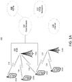
- FIG. 1A is a diagram of an example communications system 100 in which one or more disclosed embodiments may be implemented.
- the communications system 100 may be a multiple access system that provides content, such as voice, data, video, messaging, broadcast, etc., to multiple wireless users.
- the communications system 100 may enable multiple wireless users to access such content through the sharing of system resources, including wireless bandwidth.
- the communications systems 100 may employ one or more channel access methods, such as code division multiple access (CDMA), time division multiple access (TDMA), frequency division multiple access (FDMA), orthogonal FDMA (OFDMA), single-carrier FDMA (SC-FDMA), and the like.
- CDMA code division multiple access
- TDMA time division multiple access
- FDMA frequency division multiple access
- OFDMA orthogonal FDMA
- SC-FDMA single-carrier FDMA
- the communications system 100 may include wireless transmit/receive units (WTRUs) 102a, 102b, 102c, and/or 102d (which generally or collectively may be referred to as WTRU 102), a radio access network (RAN) 104, a core network 107, a public switched telephone network (PSTN) 108, the Internet 110, and other networks 112, though it will be appreciated that the disclosed embodiments contemplate any number of WTRUs, base stations, networks, and/or network elements.
- Each of the WTRUs 102a, 102b, 102c, 102d may be any type of device configured to operate and/or communicate in a wireless environment.
- the WTRUs 102a, 102b, 102c, 102d may be configured to transmit and/or receive wireless signals and may include user equipment (UE), a mobile station, a fixed or mobile subscriber unit, a pager, a cellular telephone, a personal digital assistant (PDA), a smartphone, a laptop, a netbook, a personal computer, a wireless sensor, consumer electronics, and the like.
- UE user equipment
- PDA personal digital assistant
- smartphone a laptop
- netbook a personal computer
- a wireless sensor consumer electronics, and the like.
- the communications systems 100 may also include a base station 114a and a base station 114b.
- Each of the base stations 114a, 114b may be any type of device configured to wirelessly interface with at least one of the WTRUs 102a, 102b, 102c, 102d to facilitate access to one or more communication networks, such as the core network 107, the Internet 110, and/or the networks 112.
- the base stations 114a, 114b may be a base transceiver station (BTS), a Node-B, an eNode B, a Home Node B, a Home eNode B, a site controller, an access point (AP), a wireless router, and the like. While the base stations 114a, 114b are each depicted as a single element, it will be appreciated that the base stations 114a, 114b may include any number of interconnected base stations and/or network elements.
- the base station 114a may be part of the RAN 104, which may also include other base stations and/or network elements (not shown), such as a base station controller (BSC), a radio network controller (RNC), relay nodes, etc.
- BSC base station controller
- RNC radio network controller
- the base station 114a and/or the base station 114b may be configured to transmit and/or receive wireless signals within a particular geographic region, which may be referred to as a cell (not shown).
- the cell may further be divided into cell sectors.
- the cell associated with the base station 114a may be divided into three sectors.
- the base station 114a may include three transceivers, i.e., one for each sector of the cell.
- the base station 114a may employ multiple-input multiple output (MIMO) technology and, therefore, may utilize multiple transceivers for each sector of the cell.
- MIMO multiple-input multiple output
- the base stations 114a, 114b may communicate with one or more of the WTRUs 102a, 102b, 102c, 102d over an air interface 116, which may be any suitable wireless communication link (e.g., radio frequency (RF), microwave, infrared (IR), ultraviolet (UV), visible light, etc.).
- the air interface 116 may be established using any suitable radio access technology (RAT).
- RAT radio access technology
- the communications system 100 may be a multiple access system and may employ one or more channel access schemes, such as CDMA, TDMA, FDMA, OFDMA, SC-FDMA, and the like.
- the base station 114a in the RAN 104 and the WTRUs 102a, 102b, 102c may implement a radio technology such as Universal Mobile Telecommunications System (UMTS) Terrestrial Radio Access (UTRA), which may establish the air interface 116 using wideband CDMA (WCDMA).
- WCDMA may include communication protocols such as High-Speed Packet Access (HSPA) and/or Evolved HSPA (HSPA+).
- HSPA may include High-Speed Downlink Packet Access (HSDPA) and/or High-Speed Uplink Packet Access (HSUPA).
- the base station 114a and the WTRUs 102a, 102b, 102c may implement a radio technology such as Evolved UMTS Terrestrial Radio Access (E-UTRA), which may establish the air interface 116 using Long Term Evolution (LTE) and/or LTE-Advanced (LTE-A).
- E-UTRA Evolved UMTS Terrestrial Radio Access
- LTE Long Term Evolution
- LTE-A LTE-Advanced
- the base station 114a and the WTRUs 102a, 102b, 102c may implement radio technologies such as IEEE 802.16 (i.e., Worldwide Interoperability for Microwave Access (WiMAX)), CDMA2000, CDMA2000 IX, CDMA2000 EV-DO, Interim Standard 2000 (IS-2000), Interim Standard 95 (IS-95), Interim Standard 856 (IS-856), Global System for Mobile communications (GSM), Enhanced Data rates for GSM Evolution (EDGE), GSM EDGE (GERAN), and the like.
- IEEE 802.16 i.e., Worldwide Interoperability for Microwave Access (WiMAX)
- CDMA2000, CDMA2000 IX, CDMA2000 EV-DO Code Division Multiple Access 2000
- IS-95 Interim Standard 95
- IS-856 Interim Standard 856
- GSM Global System for Mobile communications
- GSM Global System for Mobile communications
- EDGE Enhanced Data rates for GSM Evolution
- GERAN GSM EDGERAN
- the base station 114b in FIG. 1A may be a wireless router, Home Node B, Home eNode B, or access point, for example, and may utilize any suitable RAT for facilitating wireless connectivity in a localized area, such as a place of business, a home, a vehicle, a campus, and the like.
- the base station 114b and the WTRUs 102c, 102d may implement a radio technology such as IEEE 802.11 to establish a wireless local area network (WLAN).
- the base station 114b and the WTRUs 102c, 102d may implement a radio technology such as IEEE 802.15 to establish a wireless personal area network (WPAN).
- WLAN wireless local area network
- WPAN wireless personal area network
- the base station 114b and the WTRUs 102c, 102d may utilize a cellular-based RAT (e.g., WCDMA, CDMA2000, GSM, LTE, LTE-A, etc.) to establish a picocell or femtocell.
- a cellular-based RAT e.g., WCDMA, CDMA2000, GSM, LTE, LTE-A, etc.
- the base station 114b may have a direct connection to the Internet 110.
- the base station 114b may not be required to access the Internet 110 via the core network 107.
- the RAN 104 may be in communication with the core network 107, which may be any type of network configured to provide voice, data, applications, and/or voice over internet protocol (VoIP) services to one or more of the WTRUs 102a, 102b, 102c, 102d.
- the core network 107 may provide call control, billing services, mobile location-based services, pre-paid calling, Internet connectivity, video distribution, etc., and/or perform high-level security functions, such as user authentication.
- the RAN 104 and/or the core network 107 may be in direct or indirect communication with other RANs that employ the same RAT as the RAN 104 or a different RAT.
- the core network 107 may also be in communication with another RAN (not shown) employing a GSM radio technology.
- the core network 107 may also serve as a gateway for the WTRUs 102a, 102b, 102c, 102d to access the PSTN 108, the Internet 110, and/or other networks 112.
- the PSTN 108 may include circuit-switched telephone networks that provide plain old telephone service (POTS).
- POTS plain old telephone service
- the Internet 110 may include a global system of interconnected computer networks and devices that use common communication protocols, such as the transmission control protocol (TCP), user datagram protocol (UDP) and the internet protocol (IP) in the TCP/IP internet protocol suite.
- the networks 112 may include wired or wireless communications networks owned and/or operated by other service providers.
- the networks 112 may include another core network connected to one or more RANs, which may employ the same RAT as the RAN 104 or a different RAT.
- the WTRUs 102a, 102b, 102c, 102d in the communications system 100 may include multi-mode capabilities, i.e., the WTRUs 102a, 102b, 102c, 102d may include multiple transceivers for communicating with different wireless networks over different wireless links.
- the WTRU 102c shown in FIG. 1A may be configured to communicate with the base station 114a, which may employ a cellular-based radio technology, and with the base station 114b, which may employ an IEEE 802 radio technology.
- FIG. 1B is a system diagram of an example WTRU 102.
- the WTRU 102 may include a processor 118, a transceiver 120, a transmit/receive element 122, a speaker/microphone 124, a keypad 126, a display/touchpad 128, non-removable memory 130, removable memory 132, a power source 134, a global positioning system (GPS) chipset 136, and other peripherals 138.
- GPS global positioning system
- the base stations 114a and 114b, and/or the nodes that base stations 114a and 114b may represent, such as but not limited to transceiver station (BTS), a Node-B, a site controller, an access point (AP), a home node-B, an evolved home node-B (eNodeB), a home evolved node-B (HeNB), a home evolved node-B gateway, and proxy nodes, among others, may include some or all of the elements depicted in FIG. 1B and described herein.
- BTS transceiver station
- Node-B a Node-B
- AP access point
- eNodeB evolved home node-B
- HeNB home evolved node-B gateway
- proxy nodes among others, may include some or all of the elements depicted in FIG. 1B and described herein.
- the processor 118 may be a general purpose processor, a special purpose processor, a conventional processor, a digital signal processor (DSP), a plurality of microprocessors, one or more microprocessors in association with a DSP core, a controller, a microcontroller, Application Specific Integrated Circuits (ASICs), Field Programmable Gate Array (FPGAs) circuits, any other type of integrated circuit (IC), a state machine, and the like.
- the processor 118 may perform signal coding, data processing, power control, input/output processing, and/or any other functionality that enables the WTRU 102 to operate in a wireless environment.
- the processor 118 may be coupled to the transceiver 120, which may be coupled to the transmit/receive element 122. While FIG. 1B depicts the processor 118 and the transceiver 120 as separate components, it will be appreciated that the processor 118 and the transceiver 120 may be integrated together in an electronic package or chip.
- the transmit/receive element 122 may be configured to transmit signals to, or receive signals from, a base station (e.g., the base station 114a) over the air interface 116.
- a base station e.g., the base station 114a
- the transmit/receive element 122 may be an antenna configured to transmit and/or receive RF signals.
- the transmit/receive element 122 may be an emitter/detector configured to transmit and/or receive IR, UV, or visible light signals, for example.
- the transmit/receive element 122 may be configured to transmit and receive both RF and light signals. It will be appreciated that the transmit/receive element 122 may be configured to transmit and/or receive any combination of wireless signals.
- the WTRU 102 may include any number of transmit/receive elements 122. More specifically, the WTRU 102 may employ MIMO technology. Thus, in one embodiment, the WTRU 102 may include two or more transmit/receive elements 122 (e.g., multiple antennas) for transmitting and receiving wireless signals over the air interface 116.
- the transceiver 120 may be configured to modulate the signals that are to be transmitted by the transmit/receive element 122 and to demodulate the signals that are received by the transmit/receive element 122.
- the WTRU 102 may have multi-mode capabilities.
- the transceiver 120 may include multiple transceivers for enabling the WTRU 102 to communicate via multiple RATs, such as UTRA and IEEE 802.11, for example.
- the processor 118 of the WTRU 102 may be coupled to, and may receive user input data from, the speaker/microphone 124, the keypad 126, and/or the display/touchpad 128 (e.g., a liquid crystal display (LCD) display unit or organic light-emitting diode (OLED) display unit).
- the processor 118 may also output user data to the speaker/microphone 124, the keypad 126, and/or the display/touchpad 128.
- the processor 118 may access information from, and store data in, any type of suitable memory, such as the non-removable memory 130 and/or the removable memory 132.
- the non-removable memory 130 may include random-access memory (RAM), read-only memory (ROM), a hard disk, or any other type of memory storage device.
- the removable memory 132 may include a subscriber identity module (SIM) card, a memory stick, a secure digital (SD) memory card, and the like.
- SIM subscriber identity module
- SD secure digital
- the processor 118 may access information from, and store data in, memory that is not physically located on the WTRU 102, such as on a server or a home computer (not shown).
- the processor 118 may receive power from the power source 134, and may be configured to distribute and/or control the power to the other components in the WTRU 102.
- the power source 134 may be any suitable device for powering the WTRU 102.
- the power source 134 may include one or more dry cell batteries (e.g., nickel-cadmium (NiCd), nickel-zinc (NiZn), nickel metal hydride (NiMH), lithium-ion (Li-ion), etc.), solar cells, fuel cells, and the like.
- the processor 118 may also be coupled to the GPS chipset 136, which may be configured to provide location information (e.g., longitude and latitude) regarding the current location of the WTRU 102.
- location information e.g., longitude and latitude
- the WTRU 102 may receive location information over the air interface 116 from a base station (e.g., base stations 114a, 114b) and/or determine its location based on the timing of the signals being received from two or more nearby base stations. It will be appreciated that the WTRU 102 may acquire location information by way of any suitable location-determination method while remaining consistent with an embodiment.
- the processor 118 may further be coupled to other peripherals 138, which may include one or more software and/or hardware modules that provide additional features, functionality and/or wired or wireless connectivity.
- the peripherals 138 may include an accelerometer, an e-compass, a satellite transceiver, a digital camera (for photographs or video), a universal serial bus (USB) port, a vibration device, a television transceiver, a hands free headset, a Bluetooth ® module, a frequency modulated (FM) radio unit, a digital music player, a media player, a video game player module, an Internet browser, and the like.
- the peripherals 138 may include an accelerometer, an e-compass, a satellite transceiver, a digital camera (for photographs or video), a universal serial bus (USB) port, a vibration device, a television transceiver, a hands free headset, a Bluetooth ® module, a frequency modulated (FM) radio unit, a digital music player, a media player, a video
- FIG. 1C is a system diagram of the RAN 104 and the core network 107 according to an embodiment.
- the RAN 104 may employ an E-UTRA radio technology to communicate with the WTRUs 102a, 102b, 102c over the air interface 116.
- the RAN 104 may also be in communication with the core network 107.
- the RAN 104 may include eNode-Bs 160a, 160b, 160c, though it will be appreciated that the RAN 104 may include any number of eNode-Bs while remaining consistent with an embodiment.
- the eNode-Bs 160a, 160b, 160c may each include one or more transceivers for communicating with the WTRUs 102a, 102b, 102c over the air interface 116.
- the eNode-Bs 160a, 160b, 160c may implement MIMO technology.
- the eNode-B 160a for example, may use multiple antennas to transmit wireless signals to, and receive wireless signals from, the WTRU 102a.
- Each of the eNode-Bs 160a, 160b, 160c may be associated with a particular cell (not shown) and may be configured to handle radio resource management decisions, handover decisions, scheduling of users in the uplink and/or downlink, and the like. As shown in FIG. 1C , the eNode-Bs 160a, 160b, 160c may communicate with one another over an X2 interface.
- the core network 107 shown in FIG. 1C may include a mobility management gateway (MME) 162, a serving gateway 164, and a packet data network (PDN) gateway 166. While each of the foregoing elements are depicted as part of the core network 107, it will be appreciated that any one of these elements may be owned and/or operated by an entity other than the core network operator.
- MME mobility management gateway
- PDN packet data network
- the MME 162 may be connected to each of the eNode-Bs 160a, 160b, 160c in the RAN 104 via an S1 interface and may serve as a control node.
- the MME 162 may be responsible for authenticating users of the WTRUs 102a, 102b, 102c, bearer activation/deactivation, selecting a particular serving gateway during an initial attach of the WTRUs 102a, 102b, 102c, and the like.
- the MME 162 may also provide a control plane function for switching between the RAN 104 and other RANs (not shown) that employ other radio technologies, such as GSM or WCDMA.
- the serving gateway 164 may be connected to each of the eNode-Bs 160a, 160b, 160c in the RAN 104 via the S1 interface.
- the serving gateway 164 may generally route and forward user data packets to/from the WTRUs 102a, 102b, 102c.
- the serving gateway 164 may also perform other functions, such as anchoring user planes during inter-eNode B handovers, triggering paging when downlink data is available for the WTRUs 102a, 102b, 102c, managing and storing contexts of the WTRUs 102a, 102b, 102c, and the like.
- the serving gateway 164 may also be connected to the PDN gateway 166, which may provide the WTRUs 102a, 102b, 102c with access to packet-switched networks, such as the Internet 110, to facilitate communications between the WTRUs 102a, 102b, 102c and IP-enabled devices.
- the PDN gateway 166 may provide the WTRUs 102a, 102b, 102c with access to packet-switched networks, such as the Internet 110, to facilitate communications between the WTRUs 102a, 102b, 102c and IP-enabled devices.
- the core network 107 may facilitate communications with other networks.
- the core network 107 may provide the WTRUs 102a, 102b, 102c with access to circuit-switched networks, such as the PSTN 108, to facilitate communications between the WTRUs 102a, 102b, 102c and traditional land-line communications devices.
- the core network 107 may include, or may communicate with, an IP gateway (e.g., an IP multimedia subsystem (IMS) server) that serves as an interface between the core network 107 and the PSTN 108.
- IMS IP multimedia subsystem
- the core network 107 may provide the WTRUs 102a, 102b, 102c with access to the networks 112, which may include other wired or wireless networks that are owned and/or operated by other service providers.
- a VoIP packet from the speech codec arrives for transmission about every 20 ms.
- every such voice packet may in principle be sent as a single transport block (TB) in a single subframe.
- TB transport block
- sending each voice packet in a single TB in a single subframe may lead to a total of 5% UL transmission activity.
- HARQ re-transmissions may be considered when designing a coverage scheme.
- TTI bundling may be considered when considering the achievable coverage for LTE radio access.
- RLC segmentation may be considered when designing a coverage scheme.
- IP packet bundling may be considered when designing a coverage scheme.
- the amount of utilized WTRU UL transmission time may be increased both per voice packet and/or per WTRU.
- typically up to 6 HARQ retransmissions may be allowed with a 50 ms UL Uu delay budget. Therefore, a VoIP packet may be transmitted up to a total of 7 times over the duration of the same 50 ms period, assuming the Release 8/10 LTE Maximum round trip time (RTT) of 8 subframes.
- RTT Maximum round trip time
- UL coverage for a VoIP codec packet transmission in presence of HARQ may be nominally improved by a (linear) factor of 7 as compared to no HARQ.
- Such an improvement in subframe utilization may correspond to about 8.4dB more energy collected per VoIP packet by the receiver, discounting for performance aspects in presence of real-life fading channels.
- TTI bundling may be configured so as to proactively re-transmit data included in a given transport block prior to receiving any feedback regarding the reception of the TB.
- the TBs associated with the TTI bundle may be used to transmit the same data and/or different redundancy versions of the same data.
- TTI bundling may be designed to maximize the amount of time a WTRU may transmit continuously with maximum power.
- TTI bundling may repeat the same data in multiple TTIs.
- LTE Release 8 may specify a TTI bundle size of 4; however, Release 8 LTE does not specify other possible bundle sizes.
- the achievable UL performance may be increased when employing physical uplink shared channel (PUSCH) bundle sizes of both 4 and 8.
- PUSCH physical uplink shared channel
- a single TB may be channel coded and transmitted in a set of 4 consecutive TTIs.
- the bundled TTIs may be treated as a single resource, for example by utilizing a single UL grant and a single physical HARQ indicator channel (PHICH) ACK/NACK for the entire bundle.
- TTI bundling in Release 8/10 LTE may be activated through radio resource control (RRC) signaling.
- RRC radio resource control
- a evolved Node B may observe WTRU transmissions and determine a WTRU pathloss. If the WTRU pathloss exceeds a critical value and/or predetermined threshold, the eNB may activate TTI bundling.
- a VoIP codec packet including its protocol overhead may typically result in up to 7 TTIs with the existing LTE n + 4 HARQ timelines.
- a VoIP packet may be transmitted using a bundle of 4 consecutive subframes.
- a TTI bundling pattern may repeat in periods of 16 subframes. For example, for the same 50 ms UL Uu delay budget, 12 subframes (or 3 patterns that are each 16 subframes long and contain 4 TTIs) may be received by the receiver.
- TTI bundling may result in a coverage boost of approximately 2.3 dB (e.g ., 10*log10(12/7)) due to an increase in the collection of energy by the decoder.
- Second order impacts such as burst error rates (e.g ., the probability of the entire bundle in four consecutive TTIs being lost versus probability of a single TTI being lost) may be considered when designing a system with increased coverage. For example, transmission errors may often occur in bursts, so increasing the bundle size from 4 to 8 while still keeping the pattern to 16 subframes may result in an additional 1dB improvement, but perhaps not much more than that if errors occur in bursts.
- the Release 8/10 LTE RLC protocol may perform segmentation and/or concatenation of higher layer PDUs.
- One approach to improve LTE UL coverage may be to segment RLC SDUs (e.g ., VoIP codec packets including compressed IP and above headers) into several smaller units.
- MCS modulation and coding scheme
- MCS modulation and coding scheme
- the performance and drawbacks when segmenting VOIP codec packets e.g ., RLC PDUs/SDUs
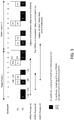
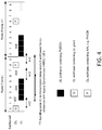
- the resulting overhead from creating smaller RLC PDUs may begin to significantly impact the achievable gains in terms of the observable Eb/No improvement when the number of RLC segments per SDU is increased beyond 4.
- Another aspect to consider may be the reduction of the number of available retransmissions per HARQ process on a per PDU basis.
- a new SDU is typically transmitted every 20 ms. This may result in N segmented PDUs occupying N HARQ processes starting every 20 ms.
- Each of these HARQ processes may remain active during the allowed 50 ms one-way Uu delay budget.
- Release 8/10 LTE since a single HARQ process per subframe or a single TB transmission per subframe may be present, when subsequent SDUs arrive for transmission, UL subframe utilization may become a limiting factor because the previous HARQ processes may still be transmitting retransmissions.
- RLC segmentation there may be a trade-off between the number of HARQ retransmissions per RLC PDU and the number of concurrent HARQ processes. Note that when RLC segmentation is used together with TTI bundling, typically no more than two RLC PDUs per SDU may be accommodated, typically resulting in four or less active HARQ processes when TTI bundling is used.
- DL IP packet bundling may be a technique that is designed to trade-off single user transmission efficiency against system capacity in LTE systems.
- IP packet bundling may be the operation of bundling multiple VoIP packets together for 1 single transmission in a subframe.
- VoIP packet bundling may be channel quality indicator (CQI) based.
- CQI channel quality indicator
- VoIP packet bundling may be applied to users which are deemed by the eNB to be in favorable channel conditions. Because bundled VoIP packets may be subject to tighter allowed one-way Uu delay budgets, on average fewer HARQ retransmissions may be used. There may be an achievable DL performance increase when aggregating 2 VoIP packets at the codec (e.g., IP or above) layer into a single TB.
- IP packet bundling may not be as effective of a technique for UL coverage improvements as for DL coverage improvement.
- the Physical Uplink Control Channel (PUCCH) and the Physical Uplink Shared Channel (PUSCH) may offer limited flexibility in terms of the configuring which resources (e.g ., resource elements) include user and/or control data versus which resources include pilot signals.
- the PUSCH may include one pilot symbol at the center of each timeslot while other transmission schemes, such as PUCCH Format 3, may include two pilot symbols per timeslot.
- PUCCH Format 3 may include a pilot signal on symbols #2 and #6 of each timeslot.
- the location of the pilot signals may be predetermined, and hence a WTRU may be unable to vary the position of the pilot signals based on link and/or channel conditions.
- PUCCH transmissions may be performed in accordance with a frequency hopping scheme.
- the frequency hopping scheme may be performed across the UL system bandwidth over the two timeslots in a subframe.
- PUSCH spatial multiplexing and/or frequency-domain scheduling gains have led to pilot signal designs such that the transmitted pilot signals are orthogonal between WTRUs transmitting on the same resource blocks. Modification of such a scheme may allow for improved link coverage, but may affect other aspects of UL system design.
- the WTRU and/or eNB may be configured to adjust the allowed one-way UL Uu delay budget for a transmitted packet. For example, typically a 50 ms air interface delays is deemed to be acceptable for UL transmission.
- the UL Uu interface delay may be a portion of the overall ear-to-mouth VoIP delay, for example along with WTRU and eNB processing times, codec delays, interface signaling durations, and/or other delay sources. Allowing for longer air interface delays may allow for more energy to be collected from each VoIP packet during the lifetime of the HARQ process. In other words, more re-transmissions may be used, increasing the likelihood of a successful decoding.
- typical end-to-end delays of the order of approximately 200 ms or less may be used to achieve a suitable voice quality.
- the portion allocated to Uu one-way delays is typically in the order of 50 ms (the remainder being absorbed by network and processing delays). Therefore, in practice the typical 50 ms delay budget numbers may be increased to delay values of the order of 60 or 70 ms for limited gain, but not much beyond such values if the mouth-to-ear delay is to be met according to current processing techniques.
- a number of techniques, methods, and systems are disclose herein to improve the reception of UL transmission in noise-limited and/or power limited scenarios. These methods are designed to increase the available signal energy and/or making more efficient use of the available signal energy at the receiver for processing UL transmissions.
- the proposed methods and systems described herein may be applied individually or in any combination.
- the methods and systems described herein may be applied when a WTRU enters or operates in a "Coverage Limited Mode” or a "Power Limited Mode.” In these modes, the WTRU may be configured to implement one or more of methods or systems described herein to improve link coverage.
- WTRUs that are not in a "Coverage Limited Mode” or a "Power Limited Mode” e.g ., "Normal Mode” may operate according to existing LTE Release 8 or Release 10 UL transmission specifications.
- a WTRU that is operating in "Normal Mode” may be triggered to transition to "Coverage Limited Mode” by an eNB, for example using RRC signaling.
- the WTRU may be configured by an eNB for operation in "Normal Mode” and "Coverage Limited Mode” through RRC signaling and the WTRU may determine the appropriate mode of operation for a given time instance based on observed conditions and/or indications received from the eNB. For example, the mode of operation (e.g., "Normal” vs.
- “Coverage Limited” may be configured dynamically by the eNB by the transmission of a MAC Control Element that indicates a specific mode or operation and/or indicates to the WTRU that it should toggle between modes (e.g ., switch from its current mode to the other mode).
- the determination by the eNB to change the mode of operation of a WTRU may be based on, but not limited to, UL power headroom (UPH) measurement reports from the WTRU and/or a request from a WTRU to change from "Normal Mode” to "Coverage Limited Mode.”
- the WTRU may autonomously determine which mode of operation to use for UL transmission, ( e.g ., "Normal Mode” or “Coverage Limited Mode”).
- the determination UL mode may be based on UPH or other measurements.
- any WTRU implementing one or more of the systems or methods described herein for improving UL coverage may be considered to be operating in "Coverage Limited Mode.”
- a WTRU may operate in a "Coverage Limited Mode” by implementing over or more of the UL coverage improvement techniques described herein ( e.g ., utilizing
- a WTRU may operate one or more (or all) HARQ processes with a shorter HARQ round trip time (RTT) (e.g., 4 subframes) than a default HARQ RTT (e.g., 8 subframes).
- RTT round trip time
- a WTRU in "Coverage Limited Mode” or "Power Limited Mode” may be configured to operate some or all HARQ processes using a shorter RTT.
- methods may be defined to dynamically adjust the HARQ RTT for the one or more HARQ process(es) and/or to dynamically change the number of subframes used for transmission of a transport block (e.g ., TBs that span multiple subframes may be used and/or the number of subframes used for transmission of a TB may be altered dynamically, for example based on channel conditions).
- a transport block e.g ., TBs that span multiple subframes may be used and/or the number of subframes used for transmission of a TB may be altered dynamically, for example based on channel conditions.
- the term HARQ process may exclude a HARQ process related to reception of system broadcasts (e.g ., HARQ process may be used to refer for HARQ processes used for transmissions that are dedicated to the WTRU).
- the term “bundling” may be used to refer to a HARQ operation by which a HARQ entity may invoke the same HARQ process for each transmission that may be part of the same bundle. For example, when bundling is used, retransmissions within a bundle may be non-adaptive and may be triggered without waiting for feedback from previous transmissions according to the size of the bundled transmission.
- the methods described herein are not limited to such a type of bundling and may be equally applicable to other form of transmission over multiple subframes including when the transmission of a single transport block may be performed over a plurality of subframes.
- the bundle size may, for example, correspond to the transmission time for the transport block.
- a typical processing sequence may include the scheduling of the HARQ process, the transmission for the HARQ process, and/or reception of feedback for the HARQ process.
- a WTRU may receive downlink control signaling that indicates a grant for an uplink resource (e.g ., dynamic scheduling).
- the WTRU may perform an autonomous synchronous HARQ retransmission without receiving any downlink control signaling for the concerned HARQ process.
- SPS semi-persistent scheduling
- the WTRU may use the configured grant in the applicable subframe if the WTRU does not receive dynamic scheduling information for the corresponding HARQ process.
- Assigning HARQ resources either implicitly or explicitly for dynamic scheduling and SPS may be referred to as scheduling of the HARQ process(es).
- a WTRU may perform a transmission on the PUSCH for a given HARQ process according to the allocated uplink resource.
- the allocated uplink resource may be dynamically scheduled and/or configured with semi-persistent scheduling.
- the retransmission times/opportunities for HARQ may be based on implicit rules. Allocating resources for transmission/retransmission either explicitly or implicitly may be referred to as transmission for the HARQ process.
- a WTRU may receive HARQ feedback on the PHICH, on the physical downlink control channel (PDCCH), and/or on both the PHICH and the PDCCH.
- the feedback may indicate whether the eNB successfully decoded a previous transmission corresponding to the applicable HARQ process.
- the feedback indication may be referred to as reception of feedback for the HARQ process.
- the timing relationships between the scheduling of the HARQ process, transmission for the HARQ process, and reception of feedback for the HARQ process may be varied for a given HARQ process.
- the subframe that corresponds to an action that is a timing reference for some future action may be referred to as subframe ( n ).
- the following timing relationships and descriptors may be used throughout this document. For example, if grant reception may occurs in subframe ( n ), HARQ transmission may occur in subframe ( n + x ) ( e.g., the HARQ transmission/data transmission may occur x subframes that the grant is received).
- the subframe utilized for HARQ transmission may be referred to as n + x.
- HARQ feedback reception may occur in subframe ( n + k ) ( e.g., the HARQ feedback may be received k subframes after the HARQ transmission associated with the received HARQ feedback was transmitted).
- the subframe utilized for HARQ feedback may be referred to as n + k.
- the WTRU-autonomous synchronous HARQ retransmission may occur in subframe ( n + y ) ( e.g., a HARQ retransmission may occur y subframes after a NACK is received).
- the subframe used for WTRU-autonomous synchronous HARQ retransmission may be referred to as n + y.
- the timing delay from HARQ transmission to HARQ feedback may be equivalent or equal to that from HARQ feedback reception to a HARQ retransmission ( e.g ., represented by n + x ).
- the corresponding timing of a subframe used for WTRU-autonomous synchronous HARQ retransmission may coincide with the subframe in which a WTRU may possibly receive a dynamic scheduling for the concerned HARQ process.
- the HARQ RTT for a given HARQ process may be further generalized as the minimum number of subframes that may be utilized and/or needed for a HARQ process to receive downlink control information that schedules the HARQ process, to perform the transmission x subframes later, and to receive HARQ feedback x subframes after the transmission.
- the timing of the HARQ feedback may implicitly also include the length of the bundle in subframes.
- TTI_BUNDLE_SIZE 4
- the timing of the HARQ feedback may be adjusted such that it may be TTI_BUNDLE_SIZE - 1 ( e.g., 3) subframes later than if bundling is not used for the transmission.
- TTI_BUNDLE_SIZE may vary from one transmission to another, for example based on various transmission parameters and channel conditions.
- the Maximum HARQ RTT for a given HARQ entity may be the maximum or largest possible HARQ RTT for any of the HARQ processes served by that HARQ entity.
- the Maximum HARQ RTT may correspond to a HARQ RTT of 8 subframes.
- the WTRU may perform uplink transmissions using up to six different HARQ processes of the HARQ entity during a given HARQ RTT.
- HARQ process n may be used for other initial transmissions that occur in subframes that are some integer multiple of x + k subframes after subframe( n ) ( e.g ., subframe( n +( x + k )), subframe( n +2( x + k )), subframe( n +2( x + k )), etc.). beginning with the subframe in which the WTRU performed the initial transmission for the HARQ process ( e.g. , subframe( n )).
- the HARQ RTT for all of HARQ processes may be equal to the Maximum HARQ RTT (e.g., 4 subframes).
- the HARQ process n may also be used for transmissions occurring in subframe( n +4), subframe( n +8), subframe( n +12), etc.
- the HARQ processes IDs may range from 0 to 3.
- the eNB may send HARQ Acknowledgement/Non-acknowledgement (A/N) Feedback 206 to the WTRU, for example via the PHICH.
- A/N HARQ Acknowledgement/Non-acknowledgement
- HARQ A/N Feedback 206 may indicate whether or not the eNB successfully received UL Transmission 204. If HARQ A/N Feedback 206 indicates that UL Transmission 204 was not successfully received, then in subframe(6), the WTRU may send UL Retransmission 208. In an example, if HARQ A/N Feedback 206 had indicated that the eNB had successfully received UL Transmission 204, the subframe(4) may have included a subsequent UL grant for subframe(6) ( e.g ., not illustrated in FIG. 2 ).
- the same HARQ process used for UL Transmission 204 could have been used for the new UL transmission in subframe(6); however, since HARQ A/N Feedback 206 indicated a negative acknowledgement, the HARQ process is used to send a UL Retransmission 208 in subframe (6), which may be an retransmission of UL Transmission 204.
- the eNB may send HARQ A/N Feedback 210 to the WTRU, for example via the PHICH, to indicate whether or not the eNB successfully received UL Retransmission 208 ( e.g ., whether the eNB was able to successfully combine UL Retransmission 208 and UL Transmission 204 to decode the UL data).
- HARQ A/N Feedback 210 indicates that the eNB was still not able to successfully decode the UL date, then in subframe(0) for the next Radio Frame (e.g ., Radio Frame i+1), the WTRU may send UL Retransmission 212.
- Each of the UL transmissions illustrated in FIG. 2 may be associated with the same HARQ process.
- the WTRU may perform UL transmission 302, which may be associated with HARQ process #0.
- the WTRU may perform UL Transmission 304, which may be associated with HARQ process #1.
- the WTRU may perform UL transmission 306, which may be associated with HARQ process #3.
- the WTRU may receive HARQ A/N Feedback 308, which may provide HARQ feedback for UL Transmission 304 corresponding to HARQ process #1.
- the WTRU may receive HARQ A/N Feedback 310, which may provide HARQ feedback for UL Transmission 302 corresponding to HARQ process #0.
- the WTRU may send UL Transmission 312 using HARQ process #1.
- UL Transmission 312 may be a new initial transmission if HARQ A/N Feedback 308 indicated that UL Transmission 304 was successfully received or may be a retransmission of UL Transmission 304 is HARQ A/N Feedback 308 indicates that UL Transmission 304 was not successfully received.
- the WTRU may receive HARQ A/N Feedback 314, which may provide HARQ feedback for UL Transmission 312 corresponding to HARQ process #1, and may also receive HARQ A/N Feedback 316, which may provide HARQ feedback for UL Transmission 306 corresponding to HARQ process #3.
- the WTRU may retransmit the same transport block using a second HARQ process that follows a first HARQ process by x + k subframes ( e.g ., possibly increasing redundancy version) when x + k is smaller than the default value.
- a second HARQ process that follows a first HARQ process by x + k subframes (e.g ., possibly increasing redundancy version) when x + k is smaller than the default value.
- This may be conceptually similar to using a single HARQ process that is active every x + k subframes, but would maintain the same number of active HARQ processes as for the default operation.
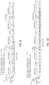
- FIG. 4 illustrates the operation of a single process in this case, where process #0 may start in subframe #2 of the first radio frame (and process #1, although not shown in FIG. 4 , may start in subframe #6 of the same radio frame).
- an LTE TTI bundling mode (e.g ., a TTI bundling size 4 is illustrated in FIG. 4 ) may now use a shorter A/N timeline of n+2/n+3.
- the WTRU may receive UL Grant 402.
- a corresponding PHICH A/N Transmission 406 may occur in subframe (n+8) (e.g., 3 subframes delay), followed by a re-transmission of the bundle via UL Transmissions 408, which may start in subframe(n+10) (e.g ., 2 subframe delay) with retransmissions occurring in subframe(n+11), subframe(n+12), and subframe(n+13).
- the bundle size may be dynamically adapted, assuming that the a bundle transmission begins in subframe( b ), then the bundle may be transmitted in subframes [ b, b + (TTI_BUNDLE_SIZE - 1)], for example, inclusively.
- the corresponding PHICH for the bundle may occur in subframe( b + (TTI_BUNDLE_SIZE - 1) + k ), followed by a retransmission of the bundle ( e.g. , if a negative acknowledgement is received) begging in subframe ( b + (TTI_BUNDLE_SIZE - 1) + k + y ).
- a different bundle size may be used for the retransmission (e.g ., a TTI_BUNDLE_SIZE different than 4 may be used after receiving a negative acknowledgement via the PHICH).
- the WTRU may begin retransmission of the bundle ( e.g ., using the same or a different TTI_BUNDLE_SIZE).
- a second HARQ event e.g ., UL grant, HARQ transmission, A/N transmission, HARQ retransmission, etc.
- a first HARQ event e.g ., UL grant, HARQ transmission, A/N transmission, HARQ retransmission, etc.
- the second HARQ event may occur in the same subframe number as the first HARQ event, but may be associated with the next radio frame in the wireless communication system.
- the WTRU may operate such that different HARQ processes may use different values for x, k, y, and/or TTI_BUNDLE_SIZE according to one or more of the following methods.
- different HARQ processes may have different x, k, y, and/or TTI_BUNDLE_SIZE for the same HARQ entity.
- the value of x , k, y, and/or TTI_BUNDLE_SIZE may be assigned and/or determined on a per HARQ process basis.
- the WTRU may be configured by an eNB with specific values of x , k, y, and/or TTI_BUNDLE_SIZE per HARQ process, or subset thereof, for example using Radio Resource Control (RRC) signaling.
- RRC Radio Resource Control
- the values of x , k, y, and/or TTI_BUNDLE_SIZE may be determined on a per HARQ entity basis. For example, different HARQ entities may have different x , k, y, and/or TTI_BUNDLE_SIZE values, but the values for that HARQ entity may be consistent across the HARQ processes associated with that HARQ entity.
- one or more HARQ process(es) may switch between different values of one or more of x , k, y, and/or TTI_BUNDLE_SIZE dynamically.
- the WTRU may change the values of one or more of x , k, y, and/or TTI_BUNDLE_SIZE for one or more HARQ processes based on implicit determinations and/or explicit signaling (or some combination thereof).
- the determination to adjust the one or more of the HARQ timing values and/or the TTI bundle size may be designed to adjust the HARQ RTT (e.g ., the WTRU may be determine and/or be configured to use faster or slower HARQ), for example on a per HARQ entity and/or on a per HARQ process basis.
- the WTRU may be configured to operate some or all HARQ processes using a TTI bundle of varying length rather than using a default TTI bundle length of 4 ( e.g., the default TTI Bundle Length may refer to the LTE R8/R9/R10/R11 Bundle Length of 4).
- the timing relationships described herein may be applicable to HARQ processes not including the HARQ process related to reception of system broadcasting.
- Layer 1 e.g ., physical layer - L1 signaling may be utilized to dynamically indicate the values of one or more of x , k, y, and/or TTI_BUNDLE_SIZE to the WTRU.
- x y
- the physical layer signaling may explicitly and/or implicitly indicate one or more of x , k, and/or TTI_BUNDLE_SIZE, and the WTRU may determine y based on the value of x .
- the value y may remain static, and the WTRU may determine changes to one or more of x , k, and/or TTI_BUNDLE_SIZE dynamically based on Layer 1 signaling.
- the WTRU may receive downlink control signaling (e.g ., via the PDCCH, for example as part of an uplink grant) that indicates what values of x , k, y, and/or TTI_BUNDLE_SIZE should be used for one or more HARQ processes.
- DCI corresponding to a UL grant may be received via the PDCCH.
- the DCI corresponding to the uplink grant may specify a specific HARQ process identification (ID) to be used for the UL grant and/or may indicate the values to use for one or more of x , k, y, and/or TTI_BUNDLE_SIZE associated with this UL grant.
- ID HARQ process identification
- the specific values themselves (and/or an indication of what configured values) for x , k, y, and/or TTI_BUNDLE_SIZE may be included in the DCI received on the PDCCH.
- the specific values may be signaled, an index value may be signaled, and/or the values may be set based on a flag.
- the value of k may be applied from the last transmission of the bundle (e.g., the timing of the HARQ feedback may vary dynamically and implicitly as a function of the size of the bundle for a given transmission).
- the value of k may be applied from the first transmission of the bundle.
- the WTRU may determine whether to change one or more of x , k, y, and/or TTI_BUNDLE_SIZE based on the value of the flag.
- the flag may be configured to toggle the WTRU between various values of one or more of x , k, y, and/or TTI_BUNDLE_SIZE.
- there may be one or more possible pre-configured values for x , k, y, and/or TTI_BUNDLE_SIZE.
- the flag may indicate whether the WTRU should switch to the next pre-configured value of one or more of x , k, y, and/or TTI_BUNDLE_SIZE.
- each of x , k, y, and/or TTI_BUNDLE_SIZE may be associated with an individual flag.
- a first flag may be used to toggle the value x
- a second flag may be used to toggle the value of k
- a third flag may be used to toggle the value of y
- a fourth flag may be used to toggle the value of TTI_BUNDLE_SIZE, etc.
- one or more flags may be used to indicate whether the values of one or more of x , k, y, and/or TTI_BUNDLE_SIZE may be changed dynamically.
- one or more flags may be used to indicate that x , k, and y are to remain statically configured, but that TTI_BUNDLE_SIZE may be dynamically changed.
- the DCI and/or flags included in the DCI may be applicable to a single HARQ parameter value ( e.g., x, k, and/or y ), to the TTI_BUNDLE_SIZE, and/or to a combination of HARQ parameter values and/or TTI_BUNDLE_SIZE.
- the WTRU may be configured with one or more cell-radio network temporary identifiers (C-RNTIs), and a given C-RNTI may be associated with certain values of one or more of x , k, y, and/or TTI_BUNDLE_SIZE.
- C-RNTIs cell-radio network temporary identifiers
- a first C-RNTI used by the WTRU may be associated with a first set of values for one or more of x , k, y, and/or TTI_BUNDLE_SIZE.
- a second C-RNTI used by the WTRU may be associated with a second set of values for one or more of x , k, y, and/or TTI_BUNDLE_SIZE.
- the WTRU may determine to use the first set of values for one or more of x , k, y, and/or TTI_BUNDLE_SIZE. If the WTRU is able to successfully decode the scheduling information using the second C-RNTI, then the WTRU may determine to use the second set of values for one or more of x , k, y, and/or TTI_BUNDLE_SIZE.
- the non-default values may be configured using RRC signaling.
- Layer 1 signaling may be used to dynamically change values for one or more of x, k, y, and/or TTI_BUNDLE_SIZE on a per HARQ process basis.
- the appropriate values for one or more of x , k, y, and/or TTI_BUNDLE_SIZE may be received as part of dynamic scheduling information that indicates a new uplink transmission.
- the values for one or more of x , k, y, and/or TTI_BUNDLE_SIZE received in dynamic scheduling information may remain valid until the HARQ process completes its current transmission/retransmission processing.
- the WTRU may use the indicated values for one or more of x , k, y, and/or TTI_BUNDLE_SIZE for the entire transmission for the concerned HARQ process and/or until some predefined event.
- the WTRU may determine to change the values for one or more of x , k, y, and/or TTI_BUNDLE_SIZE when the WTRU receives HARQ ACK feedback. In an example, the WTRU may determine to change the values for one or more of x , k, y, and/or TTI_BUNDLE_SIZE when the WTRU receives control signaling (e.g ., a PDCCH transmission) that indicates that the WTRU has been allocated UL resources for a new transmission for the concerned HARQ process.
- control signaling e.g ., a PDCCH transmission
- the WTRU may be configured to revert to one or more default values based on receiving new control signaling for the given HARQ process.
- the WTRU may be configured to change to a specific value that may or may not be indicated in the control signaling (e.g., may revert to one or more specified values that may be different than the R8/R9/R10/R11 default values for one or more of x , k, y, and/or TTI_BUNDLE_SIZE).
- the WTRU may determine to change the values for one or more of x , k, y, and/or TTI_BUNDLE_SIZE when the maximum number of HARQ retransmission(s) is reached for the concerned HARQ process.
- the WTRU may continue to utilize a configured value for one or more of x , k, y, and/or TTI_BUNDLE_SIZE until a new value is received. For example, if a first set of values for one or more of x , k, y, and/or TTI_BUNDLE_SIZE is received ( e.g., via scheduling information and/or the like), the WTRU may continue to treat the received values as valid until the WTRU receives signaling that indicates a new value for the one or more of x , k, y, and/or TTI_BUNDLE_SIZE.
- the WTRU may determine that the previous value for x is no longer valid, but that the previous values for k, y, and/or TTI_BUNDLE_SIZE are still valid (e.g., the WTRU treats previous values for HARQ/TTI Bundling parameters as no longer valid only for the HARQ/TTI Bundling parameters for which a new value is received).
- the WTRU may determine that the previously received values for each of x , k, y, and/or TTI_BUNDLE_SIZE is/are no longer valid. For example, if the WTRU receives a new value for x , but not for k, y, and/or TTI_BUNDLE_SIZE, the WTRU may determine that the previous value for x is no longer valid, and that the previous values for k, y, and/or TTI_BUNDLE_SIZE are also no longer valid even though specific values for those parameters have not been received. In an example, if the since specific values were not received for k, y, and/or TTI_BUNDLE_SIZE, the WTRU may determine to use default values for those parameters.
- the WTRU may be configured to use the default values for one or more of x, k, y, and/or TTI_BUNDLE_SIZE until some other configuration of HARQ/TTI Bundling parameters is activated.
- an eNB may configure the WTRU with some non-default configuration of HARQ/TTI Bundling parameters, for example using RRC signaling.
- the non-default configuration may be associated with non-default values for one or more of x, k, y, and/or TTI_BUNDLE_SIZE.
- the WTRU may then receive an activation message that indicates to the WTRU that the pre-configured non-default configuration should be utilized.
- the activation message may be sent by the eNB via a PDCCH order, an L1 activation command, MAC control element (CE), an RRC message, and/or some other control signaling that indicates that the WTRU should use a non-default HARQ parameter/TTI Bundling configuration.
- the WTRU may transmit HARQ feedback for the activation message.
- the activation message may include the non-default values for one or more of x , k, y, and/or TTI_BUNDLE_SIZE and/or may indicate which of the one or more of x, k, y, and/or TTI_BUNDLE_SIZE parameters should use a non-default value included in a previously configured non-default configuration. If the WTRU had been previously configured to use more than one non-default HARQ parameter/TTI Bundling configuration, then the activation message may indicate which non-default HARQ parameter/TTI Bundling configuration should be used.
- the non-default values for x and/or k and/or the non-default HARQ parameter/TTI Bundling configuration may be valid once activated and may remain valid until they are deactivated or a new value(s) is activated.
- a deactivation message may be sent by the eNB via a PDCCH order, an L1 activation command, MAC CE, an RRC message, and/or some other control signaling that indicates that the WTRU should no longer use the non-default HARQ parameter/TTI Bundling configuration.
- Layer 1 signaling may also be applied to configured values for one or more of one or more of x, k, y, and/or TTI_BUNDLE_SIZE on a per HARQ entity basis and/or on a per WTRU basis ( e.g ., rather than on a per HARQ process basis).
- the Layer 1 signaling may be applicable to set or configure values for one or more of x, k, y, and/or TTI_BUNDLE_SIZE for a plurality of HARQ processes, such as each of the HARQ processes within a HARQ entity.
- the L1 activation and/or deactivation commands may be applicable per HARQ entity and/or for some or all of the HARQ entities of the WTRU ( e.g ., in case the WTRU is configured with multiple serving cells).
- Layer 2 e.g., MAC
- control signaling may be utilized to dynamically configure values for one or more of x , k, y, and/or TTI_BUNDLE_SIZE and/or to set or establish a HARQ/TTI Bundling parameters configuration.
- MAC signaling may be used to activate a configuration for a shorter RTT (e.g ., is to configure values of one or more of x , k, y, and/or TTI_BUNDLE_SIZE such that the RTT is less than the default value of 8 subframes).
- the WTRU may apply a configuration indicated by MAC signaling after a certain delay from the successful reception of the MAC CE that indicated that change. For example, the WTRU may wait for at least one default HARQ RTT to occur after receiving the MAC CE before changing. In another example, the WTRU may wait for one HARQ RTT corresponding to the RTT for the previous configured HARQ/TTI Bundling parameters configuration prior to applying the new configuration indicated by the MAC CE.
- the WTRU may receive a MAC CE that indicates specific values of one or more of x , k, y, and/or TTI_BUNDLE_SIZE to be used for a given HARQ process, given HARQ entity, and/or for the WTRU.
- specific values or an indication of configured values using an index
- TTI_BUNDLE_SIZE may be included in a MAC CE received on from the eNB.
- the MAC CE may not specifically include the values of x , k, y, and/or TTI_BUNDLE_SIZE, but may trigger the WTRU to transition to a different HARQ/TTI Bundling parameters configuration.
- the HA HARQ/TTI Bundling parameters configuration may be preconfigured via RRC signaling, and if there are multiple preconfigured HARQ/TTI Bundling parameters configurations, the MAC CE may indicate which HARQ/TTI Bundling parameters configuration to use.
- the MAC CE may not indicate which HARQ/TTI Bundling parameters configuration to use, but the WTRU may select the appropriate HARQ/TTI Bundling parameters configuration based on some implicit criteria.
- the MAC CE signaling may be applicable to a plurality of HARQ processes, for example each of the HARQ processes associated with a given HARQ entity and/or each of the HARQ processes associated with some or all of the HARQ entities utilized by the WTRU.
- a MAC CE may be used to activate a previously configured HARQ/TTI Bundling parameters configuration for the WTRU.
- the MAC CE may be a command that activates specific values of one or more of x , k, y, and/or TTI_BUNDLE_SIZE that had been previously configured for and/or provided to the WTRU.
- the values may be applicable per HARQ entity, and/or for each of HARQ entities of the WTRU (e.g., in case the WTRU is configured with multiple serving cells).
- the MAC CE may indicate what serving cell the MAC CE command applies to, for example if the command applies the HARQ entity associated with that serving cell but not to HARQ entities associated with other serving cells.
- Layer 3 e.g., RRC
- control signaling may be utilized to dynamically and/or semi-statically configure HARQ/TTI Bundling parameters configuration and/or specific values for one or more of x , k, y, and/or TTI_BUNDLE_SIZE.
- the WTRU may be configured by RRC with configurations for one or more of x , k, y, and/or TTI_BUNDLE_SIZE that may be applicable per cell, per WTRU, per HARQ process, and/or per type of transmission (e.g ., SPS, dynamic, synchronized retransmissions, etc.).
- the WTRU may receive an RRC configuration that indicates what values of one or more of x , k, y, and/or TTI_BUNDLE_SIZE may be used for one of more HARQ processes (e.g., an HARQ/TTI Bundling parameters configuration).
- the values may be configured per HARQ process, per HARQ entity ( e.g ., per serving cell), and/or for each of the HARQ processes of the concerned WTRU.
- the WTRU may perform a reconfiguration of the HARQ process and/or HARQ parameter/TTI Bundling configuration during an RRC Connection Reconfiguration procedure.
- the WTRU may be configured to perform reconfiguration of a HARQ process (e.g., establish new values for one or more of x , k, y, and/or TTI_BUNDLE_SIZE and/or re-validate the previous values for one or more of x , k, y, and/or TTI_BUNDLE_SIZE) and/or an RRC Connection Reconfiguration procedure when the receives control signaling that changes the active set of values for one or more of x , k, y, and/or TTI_BUNDLE_SIZE.
- a HARQ process e.g., establish new values for one or more of x , k, y, and/or TTI_BUNDLE_SIZE and/or re-validate the previous values for one or more of x , k, y, and/or TTI_BUNDLE_SIZE
- RRC Connection Reconfiguration procedure when the receives control signaling that changes the active set
- the timing of a frame and/or subframe may be used to determine values for one or more of x , k, y, and/or TTI_BUNDLE_SIZE.
- the WTRU may determine the values of one or more of x , k, y, and/or TTI_BUNDLE_SIZE based on the timing of the subframe in which a given transmission ( e.g ., initial transmission, re-transmission, final transmission, etc.) is scheduled to take place.
- the WTRU may determine the values of one or more of x , k, y, and/or TTI_BUNDLE_SIZE based on the timing of the subframe in which a grant for a given transmission was received.
- Such timing may be based on the position of the subframe during which the triggering event (e.g ., HARQ transmission, UL grant, PHICH transmission, etc.) occurred within a frame ( e.g ., based on subframe number but not frame number) and/or relative to a window of more than 1 frame ( e.g ., 4 or 8 frames).
- a WTRU may be configured to determine that TTI_BUNDLE_SIZE may be set to four for a transmission starting in the 20th subframe after the start of the window ( e.g ., the first subframe of the 3rd radio frame in the window).
- a WTRU may determine to use a TTI_BUNDLING_SIZE of two based on the transmission beginning to take place in the 22nd subframe after the start of the window (e.g. , the third subframe of the 3rd radio frame in the window).
- the timing information e.g., a configuration indicating the timing relationships that are based on the determination of when a reference even occurred
- one or more properties of an uplink transmission may be used to determine appropriate values for one or more of x , k, y, and/or TTI_BUNDLE_SIZE.
- the WTRU may determine the values of for one or more of x , k, y, and/or TTI_BUNDLE_SIZE based on the properties of the resources allocated to a WTRU in a UL grant. If values for one or more of x , k, y, and/or TTI_BUNDLE_SIZE are determined based on a property of an UL grant, the values may be applicable to the transmission associated with the grant or to transmissions associated with the HARQ process utilized by the grant.
- properties of an UL transmission that may be used to determine values for one or more of x , k, y, and/or TTI_BUNDLE_SIZE to be used for transmitting the UL transmission (and/or any applicable retransmission) may include one or more of the resource block allocation (e.g ., starting resource block (RB), number of RBs, etc.), a property of a transmitted and/or received DM-RS reference signal transmitted (e.g ., the identity of which may be determined based on a field of a received grant), a property related to the transmission power (such as the transmission power itself, the power headroom, and/or the like), and/or the uplink frequency (e.g ., carrier frequency).
- the resource block allocation e.g ., starting resource block (RB), number of RBs, etc.
- a property of a transmitted and/or received DM-RS reference signal transmitted e.g ., the identity of which may be determined based on a field of a received grant
- the properties of the received DM-RS that may be used by the WTRU to determine values for one or more of x , k, y, and/or TTI_BUNDLE_SIZE may include the base sequence, the cyclic shift, the hopping patterns thereof, the orthogonal cover code, and/or the like.
- values for one or more of x , k, y, and/or TTI_BUNDLE_SIZE may be a function of the number of transmissions for a given transport block and/or for a given HARQ process.
- the size of a bundle for a given HARQ transmission may be a function of the number of transmission and retransmission(s) for a given transport block.
- a HARQ process may use a set of bundle size values (e.g., size_1, size_2, ... , size_N, where N may be equal to a total maximum number of HARQ transmissions for the process) that may be applicable to the transmission of a transport block for a given HARQ process.
- such a sequence may be [8, 6, 4, 2] for a process for which the maximum number of retransmissions is equal to 3.
- a function may be used, for example where the bundle size may be halved for each retransmission of a transport block of a given HARQ process down to a minimum value ( e.g ., no smaller than 1).
- the WTRU may autonomously determine the size of the bundle using the function for non-adaptive WTRU-autonomous retransmissions.
- the HARQ process may switch between different values for one or more of x , k, y, and/or TTI_BUNDLE_SIZE dynamically at a new HARQ transmission instance.
- the WTRU may receive dynamic scheduling that indicates a new transmission for a given HARQ process.
- the scheduling information may include an indication that of the values for one or more of x , k, y, and/or TTI_BUNDLE_SIZE to be used for the HARQ process until the process completes.
- the WTRU may determine the identity of the HARQ process, may determine that the corresponding transmission may be performed in subframe n + x , and may expect HARQ feedback k subframes later. If the HARQ feedback is negative, the retransmission (e.g. , either WTRU-autonomous, or dynamically scheduled) may occur y subframes later, and subsequent retransmission may follow the same timing until the process has completed.
- a HARQ process may switch between different values for one or more of x , k, y, and/or TTI_BUNDLE_SIZE dynamically for each new HARQ transmission.
- the WTRU may receive dynamic scheduling that may indicate a new transmission for a given HARQ process.
- the scheduling information may include an indication for one or more values for one or more of x , k, y, and/or TTI_BUNDLE_SIZE.
- TTI_BUNDLE_SIZE 8 may be used for the HARQ process until the process is complete.
- the WTRU may determine the identity of the HARQ process, may determine that it may perform the first transmission in the bundle in subframe n , and the remainder of the bundle from n +1 until n +7.
- the WTRU may also determine that it may expect HARQ feedback for the bundle as described herein.
- Retransmissions e.g ., WTRU-autonomous, and/or dynamically scheduled
- the HARQ process may switch between different values for one or more of x , k, y, and/or TTI_BUNDLE_SIZE dynamically per HARQ transmission and/or retransmission.
- the WTRU may receive dynamic scheduling that indicates a new transmission for a given HARQ process.
- the scheduling information may include an indication of the values for one or more of x , k, y, and/or TTI_BUNDLE_SIZE to be used for the initial transmission.
- the WTRU may determine the identity of the HARQ process, may determine that it may perform the corresponding transmission in subframe n + x , and may expect HARQ feedback k subframes later.
- the dynamic scheduling information may include new values for one or more of x , k, y, and/or TTI_BUNDLE_SIZE.
- the WTRU may use new values indicated in the received control signaling (e.g ., in the dynamic retransmission grant), otherwise if a dynamic grant is not received or the dynamic grant does not indicate the new values for one or more of x , k, y, and/or TTI_BUNDLE_SIZE, then the WTRU may use the default values for one or more of x , k, y, and/or TTI_BUNDLE_SIZE and/or may use the values for one or more of x , k, y, and/or TTI_BUNDLE_SIZE that were associated with the initial transmission.
- the values for values for one or more of x , k, y, and/or TTI_BUNDLE_SIZE may be applied according to a set of predefined rules. For example, the WTRU may determine to apply a first HARQ/TTI Bundling parameters configuration for initial transmissions associated with a dynamic grants and a second HARQ/TTI Bundling parameters configuration for retransmissions. Continuing with this example, the WTRU may determine to apply a third HARQ/TTI Bundling parameters configuration for transmissions associated configured grants/SPS. In such as cases, the values for one or more of x , k, y, and/or TTI_BUNDLE_SIZE associated with the first, second, and/or third HARQ/TTI Bundling parameters configuration may be different.
- the WTRU may apply specific values for one or more of x , k, y, and/or TTI_BUNDLE_SIZE for uplink transmissions that are dynamically scheduled (e.g. , granted via a PDCCH DCI).
- the WTRU may apply a second set of values for one or more of x , k, y, and/or TTI_BUNDLE_SIZE for uplink synchronized retransmissions (e.g., may apply also to asynchronous HARQ).
- the WTRU may apply a specific set of values for one or more of x , k, y, and/or TTI_BUNDLE_SIZE for uplink transmissions using a configured grant (e.g ., may also be applicable to HARQ processes configured with a Semi-Persistent Scheduling grant).
- the values applied to configured grant transmissions/SPS transmissions may be different than values used for dynamically scheduled grants.
- Another type of transmission that may be associated with an individualized HARQ/TTI bundling parameters configuration may include transmission of msg3 using a grant received in a random access response (RAR).
- the WTRU may apply specific values for one or more of x , k, y, and/or TTI_BUNDLE_SIZE for uplink transmissions of msg3 using a grant received in a RAR (e.g ., these values may also apply to the HARQ process for RACH msg3 and/or RACH msg3 transmission).
- the WTRU may apply specific values for one or more of x , k, y, and/or TTI_BUNDLE_SIZE when cross-carrier scheduling is not configured for the concerned serving cell, for example if carrier aggregation is configured for the WTRU.
- the WTRU may apply specific values for one or more of x , k, y, and/or TTI_BUNDLE_SIZE for any and/or all uplink transmissions for which a HARQ feedback is expected.
- the WTRU may revert to the default timing and/or bundle size for this process. This may be the case if the values for one or more of x , k, y, and/or TTI_BUNDLE_SIZE are adjusted dynamically for the concerned process according to other methods described herein.
- a bundle size e.g., values for one or more of x , k, y, and/or TTI_BUNDLE_SIZE
- dynamic adjustments of values for one or more of x , k, y, and/or TTI_BUNDLE_SIZE may not be applied to a HARQ process for the random access procedure.
- the WTRU may apply the default values for one or more of x , k, y, and/or TTI_BUNDLE_SIZE (or may apply some other static values) for transmission/reception of RACH msg3 following the reception of a grant in a RAR.
- the methods for dynamically modifying the HARQ timing values may not be applicable to the reception of HARQ feedback for msg3.
- t dynamic adjustments of values for one or more of x , k, y, and/or TTI_BUNDLE_SIZE may not be applied to a HARQ process associated with a configured grant.
- the WTRU may apply the default values for one or more of x , k, y, and/or TTI_BUNDLE_SIZE (or may apply some other static values) for transmission/reception configured by semi-persistent scheduling.
- HARQ processes configured for and/or reserved for SPS may apply the default values for one or more of x , k, y, and/or TTI_BUNDLE_SIZE (or may apply some other static values).
- the timing and/or bundling values may be modified for the HARQ process.
- a WTRU operating according to the fast HARQ may derive a corresponding PHICH resource assignment for a DL subframe n carrying PHICH based on transmission settings chosen for UL subframe n-k carrying PUSCH, for example a starting resource block (RB).
- the PHICH resource assignment may be determined by the WTRU as a function of one or more signaled and explicitly configured resource assignment value(s).
- Two or more PHICH resources may be monitored by a WTRU in a subframe supporting fast HARQ, where a first PHICH index may be determined based on a signaled parameter(s), previous transmission settings, and/or a combination of thereof.
- a second PHICH resource to be monitored in that same subframe may be determined by the WTRU based on an offset value.
- the offset value may be determined by the WTRU based on fixed value, it could be derived or obtained from a signaled parameter, and/or it may be determined based on one or more previous transmission settings.
- a collision between PHICH resource assignments in a DL subframe n for a Fast HARQ process and for one or more legacy HARQ process(es) may allow the PHICH resource assignment to be shared between the processes.
- HARQ feedback information may be provided along with an explicit indication of the HARQ process of which the information may pertain.
- Such an indication may include the HARQ process index itself (e.g., 0-7; 0-15, 0-31, etc., for example if more than 8 HARQ processes may be utilized) and/or of an indication to one of a subset of possible HARQ processes that may collide. For example, if feedback for two HARQ processes may possibly collide, then the feedback for the first HARQ process may be assigned a first index (e.g., 0) and feedback for the second HARQ process may be assigned a second index (e.g., 1). The index may be transmitted with the HARQ feedback.
- the indication and associated HARQ information may be provided in a downlink control information message (e.g ., carried over PDCCH and/or E-PDCCH).
- HARQ feedback information from multiple HARQ processes may be combined into a single indication (e.g ., HARQ bundling may be performed).
- an ACK indication may be provided if the HARQ information for each of the HARQ processes associated with the bundled feedback is an ACK, while a NACK may be provided otherwise.
- the WTRU may send a NACK indication, but if the HARQ feedback for each of the bundled processes is an ACK, the WTRU may send an ACK indication.
- HARQ feedback information may be provided for a subset of HARQ processes or even a single HARQ process according to a priority rule between the HARQ processes.
- the WTRU may assume a specific HARQ feedback (e.g ., ACK) for the other processes for which the information may not be provided based on feedback for one or more other HARQ process that are provided.
- ACK HARQ feedback
- the priority rule may be based on one or more of an order between processes that may be pre-defined (e.g ., based on index) or provided by higher layers, associated parameters such as the TTI bundle size, n, k, and / or y, the HARQ/TTI bundling parameters configuration, the delay since the initial transmission from each process ( e.g ., the process which started earlier may have higher priority), and/or the like.
- link coverage may be enhanced by introducing the option of utilizing transmission time intervals (TTIs) that span an interval longer than a single subframe of 1 ms.
- TTIs transmission time intervals
- a WTRU configured to operate in a "Coverage Limited Mode” and/or a "Power Limited Mode” may be configured to utilize a longer TTI for some or all transmissions that occur while in the "Coverage Limited Mode” and/or the "Power Limited Mode.”
- the following examples and features related to the enabled use of longer TTIs may be implemented in any combination. Longer TTIs may also be used in combination with other linker coverage improvement techniques described herein.
- long TTI and “longer TTI” may refer to a TTI that is longer than 1 ms ( e.g ., either via contiguous or non-contiguous subframes).
- normal TTI may refer to a TTI that is a 1 ms in length.
- transport blocks may be transmitted in a long TTI.
- Each transport block may be channel coded using one or more of the following coding steps: cyclic redundancy check (CRC) addition, code block segmentation, CRC attachment, channel coding, rate matching, code block concatenation, multiplexing with control information, and/or channel interleaving.
- CRC cyclic redundancy check
- the set of coded bits transmitted during a long TTI may correspond to one or more of the redundancy versions typically used for a normal TTI.
- the WTRU may be configured to transmit different redundancy versions of the same encoded transport block(s) (e.g., and the same HARQ process) in different TTIs and/or in a single long TTI.
- the set of coded bits transmitted during a long TTI may correspond to one or more of a number of possible redundancy versions according to a predetermined rule, WTRU configuration, and/or signaling from the eNB.
- the encoding may be such that a single redundancy version is defined.
- the channel interleaver may be configured such that symbols corresponding to adjacent coded bits may be mapped to resource elements in non-adjacent subframes after the operation of mapping to resource elements. Doing so may enhance time diversity.
- physical layer processing such as scrambling, modulation and resource mapping may be modified for transmission using a longer TTI.
- Bits for transmission such as coded and interleaved bits, may be scrambled, modulated to generate symbols, mapped onto at least one transmission layer, transform precoded, precoded, and/or mapped to resource elements.
- the layer mapping and precoding steps may be such that symbols mapped to resource elements in adjacent sub frames are transmitted on different layers and/or different antenna ports after the operation of mapping to resource elements. Doing so may increase diversity.
- the bits transmitted in the first subframe may be transmitted on a first MIMO transmission layer and/or first antenna port and the bits transmitted in the second subframe may be transmitted on a second MIMO layer and/or a second antenna port.
- mapping to resource elements and subframes may be modified for transmission using a longer TTI.
- a sequence of symbols may be generated for at least one antenna port. These symbols may be mapped onto resource elements of a number of subframes N, where N may be larger than 1 (e.g., in an example the N subframes may represent the length of the longer TTI).
- N may be larger than 1 (e.g., in an example the N subframes may represent the length of the longer TTI).
- the WTRU may be configured to refrain from using these resource elements when mapping the bits of the transport block(s) to the appropriate resource elements.
- the mapping to resource elements with more than one subframe may be such that the symbols are mapped to resource elements by order of subframe timing first, time within a subframe second, and frequency last.
- the bits may first be assigned to a given subframe, then mapped to resource elements increasing in time across a first subcarrier in (e.g., time-first mapping across OFDM symbols of a subcarrier), then mapped to resource elements increasing in time across a second subcarrier, etc. until allocation in the given subframe has been utilized.
- a second subframe may be selected, and the remaining bits may be mapped in time-first order across the sub-carriers assigned to the WTRU for the second subframe.
- the mapping may be such that the symbols (e.g ., coded bits) are mapped to resource elements by order of time within a subframe first, subframe timing second, and frequency last.
- the bits may be first mapped to the first resource element of the first subframe of the first subcarrier assigned to the WTRU.
- the remaining bits may be mapped to the first resource element of the second subframe at the first subcarrier assigned to the WTRU.
- the remaining bits may then be mapped to the first resource element of the first subcarrier across the remaining subframes assigned to the WTRU.
- the remaining bits may be mapped to the second resource element of the first subcarrier of the first subframe, followed by the second resource element of the first subcarrier of the second subframe, and so on until each of the resource elements of the first subcarrier have been utilized.
- the process may then be repeated for the second subcarrier, third subcarrier, etc. until each of the subcarriers have been utilized or the data for transmission has been exhausted.
- these resource element mapping methods increase the time diversity of the channel by mapping symbols corresponding to adjacent channel coded bits to resource elements that are further apart in the time domain.
- the N subframes may be consecutive in the time domain. Utilizing consecutive subframes in the time domain for an extended TTI may minimize the transmission delay of transport block(s) transmitted in the longer TTI. Additionally, by utilizing consecutive subframes in the time domain for a long TTI, each of the subframes onto which a long TTI is mapped may occur before any subframe onto which a subsequent long TTI is mapped. An example of utilizing consecutive subframes in the time domain for a long TTI is illustrated in FIG. 5 .
- the N subframes may be a subset of subframes within a set of M subframes, for example according to a pre-determined or signaled pattern.
- the subframes associated with a long TTI may be non-consecutive.
- the number of subframes M may be set such that the transmission delay of a transport block may be maintained within a certain delay requirement.
- a delay requirement for a VoIP packet may be 40 ms, so M may be selected to be 40.
- M may be selected to be less than 40, for example 20 or 10.
- FIG. 7 illustrates another example of possible configuration of a long TTI.
- the long TTI may allow for the transmission of two redundancy versions within the long TTI for each transport block.
- a total of 4 TTIs may be transmitted over the 40 ms period.
- a first TTI e.g., TTI# 1
- a first redundancy version e.g., RV# 0
- a first transport block e.g., Transport Block A
- a first redundancy version (e.g., RV# 0) of a second transport block (e.g., Transport Block B) may be transmitted.
- a second redundancy version (e.g., RV# 1) of the first transport block (e.g., Transport Block A) may be transmitted.
- a fourth TTI (e.g., TTI# 4) a second redundancy version (e.g., RV# 1) of the second transport block (e.g ., Transport Block B) may be transmitted.
- the use of the long TTIs interleaved in the time domain may allow for the transmission of multiple redundancy versions of various transport blocks while achieving time diversity and still meeting delay requirements.
- uplink control information such as HARQ A/N and/or CSI may be multiplexed with PUSCH on a per-subframe basis.
- the UCI may be encoded and multiplexed such that symbols are mapped to a known subset of resource elements in a given subframe, resulting in puncturing of PUSCH symbols that would normally be mapped to these resource elements (e.g., UCI, rather than PUSCH data, may be mapped to these resource elements).
- the WTRU may transmit UCI that is decodable on a per-subframe basis even if the PUSCH is transmitted over a long TTI.
- the UCI or part of the UCI may be multiplexed with PUSCH data prior to channel interleaving and mapping to resource elements of PUSCH, such that the UCI may be decodable along with PUSCH.
- UCI may be mapped to a predetermined set of symbols in a given timeslot or subframe.
- UCI may be mapped to symbols that are adjacent to the modulation symbols that carry pilot signals.
- a WTRU may determine a subset of subcarriers for the mapping of UCI and then map the UCI to resource elements in the determined subset of subcarriers. The WTRU may avoid mapping the UCI to resource elements used for the transmission of reference signals.
- UCI may correspond to un-coded UCI bits or symbols, to channel-coded sequences derived from the un-code UCI bits or symbols, and/or portions or subsets of channel-coded bits that are relevant for mapping in a given time interval such as a timeslot, subframe and/or TTI ( e.g ., normal and/or long).
- the randomization function may operate on a per-symbol, per-timeslot, per-subframe and/or per-TTI (e.g ., long and/or normal) basis.
- the randomization function may be based on a combination of parameters, for example operating on a combination of a per-symbol, per-timeslot, per-subframe and/or per-TTI basis ( e.g ., long and/or normal).
- the randomization parameters employed by the WTRU may be varied in a random and/or known order in order to generate a sequence of different selected transmission parameters for input to the randomization function.
- the randomization function used to generate the mapping of UCI may result in the use of different cyclic shift values, different spreading codes, different input positions to the discrete Fourier transform (DFT) operation or to the inverse fast Fourier transform (IFFT) operation for a signal that includes UCI, and/or different symbol positions within a given transmission for a signal(s) carrying UCI.
- the mapping of UCI onto time-/frequency resources for UL transmission may be determined by the WTRU as a function randomization parameters, such as symbol number, timeslot number, subframe number, and/or TTI number ( e.g ., long and/or normal).
- the WTRU may determine the UL transmission scheme based on a table of stored randomization values. In an example, the WTRU may determine the randomization values as a function of one or more transmission parameters (e.g ., symbol number, timeslot number, subframe number, and/or TTI ( e.g ., long and/or normal) number, etc.). For example, when multiplexing channel-coded ACK/NACK (AN) bits into a timeslot or subframe using a given transmission scheme, the OFDM symbol position for mapping such AN bits may be varied on a per-timeslot and/or per-subframe basis.
- AN channel-coded ACK/NACK
- a first (set of) AN bit(s) or a channel-coded sequence computed from AN bits may be mapped to symbol positions #2 and #4.
- a second (set of) AN bit(s) or a channel-coded sequence computed from AN bits may be mapped to symbol positions #1 and #5.
- the first and the second sets of AN bits and/or the first and second sets channel-coded sequences may be the same/identical, for example when the same UCI is repeated in more than one timeslot or subframe.
- the first and the second sets of AN bits and/or the first and second sets channel-coded sequences may be different sets of AN bits and/or different sets of channel-coded sequences in the first and second timeslots or subframes.
- different spreading codes, cyclic shifts, and/or DFT/IFFT encoding parameters may be selected by a WTRU as a function of symbol, timeslot, subframe and/or TTI (e.g ., long and/or normal) numbers.
- a first (set of) AN bit(s) or a channel-coded sequence computed from AN bits may be encoded using a first spreading code of a given length.
- a second (set of) AN bit(s) or a channel-coded sequence computed from AN bits may be encoded using a second spreading code of a given length.
- the first and the second set of AN bits and/or first and second channel-coded sequences may be the same/identical, for example when the same UCI is repeated in more than one timeslot or subframe.
- the first and the second set of AN bits and/or first and second channel-coded sequences may be different sets of AN bits and/or different sets of channel-coded sequences in the first and second symbol, timeslot or subframe.
- the WTRU may utilize both normal-length TTI (e.g ., single subframe) and long TTI.
- normal-length TTIs and long TTIs may be mapped to subframes according to a pre-determined or pre-signaled pattern, where the signaling may take place at higher layers (e.g ., MAC or RRC).
- MAC or RRC e.g ., MAC or RRC
- sub-frame #9 of radio frame #i may utilized by a normal length (e.g., TTI# 3).
- a first long TTI e.g., TTI# 2
- TTI# 3 a first long TTI
- 9 subframes instead of 10 subframes.
- Long TTIs that are not punctured to accommodate the transmission of a normal TTI e.g., or some other TTI of various length
- may utilize the normal number of subframes associated with the long TTI e.g., 10 subframes in this example).
- Whether a long TTI is to be punctured to accommodate that transmission of some other TTI may be taken into account during the operation of channel coding and multiplexing, since it may be known in advance that punctured TTI will be mapped on a smaller number of resource elements.
- normal-length TTIs and long TTIs may be mapped to subframes according to a pattern that may be undetermined or unknown at the time the data to be transmitted over a long TTI is processed. For example, such a situation may occur if a high-priority bearer is to be scheduled.
- the WTRU may determine at subframe n that data for a high-priority bearer is to be scheduled at subframe n + m ( e.g., where m may be 2 or 4), for example based on the reception of a dynamic grant from a downlink control channel.
- the WTRU may use a portion and/or all of the resource elements of a subframe that would normally be used for PUSCH transmission of data for the long TTI to transmit PUSCH data for the normal TTI instead (e.g ., data scheduled by the recently received dynamic grant). Successful reception of the data from the long TTI may still be possible at the receiver considering the use of channel coding and interleaving and/or transmission of multiple redundancy versions.
- normal-length TTIs and long TTIs may be mapped to the same subframe for certain subframes, but occupy different sets of resource elements (e.g ., in adjacent frequencies to avoid non-linearities). Whether to map both a normal TTI and a long TTI to the same subframe may be indicated in a grant from a downlink control channel or from higher layers. Channel coding, interleaving, and subsequent physical layer processing make take place independently for the data to be transmitted on each TTI.
- a WTRU may have a reduced number of UL subframes (e.g ., as compared with number of subframes available using previous radio access techniques) to utilize in order to successfully deliver a given TB (e.g ., VoIP packet, segment of a VoIP packet, etc.) during an allowed transfer time interval.
- a WTRU could suffer from UL coverage problems if radio problems persist during the shortened subframe window use for a UL transmission.
- the UL subframe utilization ratio with existing LTE radio technology may be less than 100%.
- every UL subframe may not be used by the WTRU in typical LTE deployments.
- multiple concurrent UL HARQ processes may be active during the allowed UL transfer delay of 50 ms for each packet.
- dedicated PUSCH allocations to a WTRU may be utilized in order to improve LTE UL coverage.
- Dedicated PUSCH allocations may refer to allocations of the PUSCH that repeat over time and/or occur in pre-specified times, frequencies, and/or locations.
- a dedicated PUSCH allocation may allocate certain resources to the WTRU in every UL subframe for the life of the allocation (e.g., may be until the allocation is revoked).
- the eNB may reserve the future transmission resources for the dedicated PUSCH allocation.
- a WTRU may be able to create/receive PUSCH allocations that possess an inherently higher transmission density (e.g ., more frequent transmission opportunities in time domain) than are supported by the existing LTE n +8 UL HARQ re-transmission delays (e.g ., even in presence or absence of TTI bundling).
- the UL receiver e.g ., the eNB
- the eNB may collect significantly more energy for successfully decoding a TB during the allowed transfer time interval when dedicated PUSCH allocations are utilized than what is possible by using existing LTE radio access procedures. This may facilitate successful decoding in time limited scenarios, for example when a given TB may correspond to a VoIP packet including overhead and/or segments of such a packet.
- Operation of dedicated PUSCH allocations may be implemented together with a dynamic grant mechanism and/or with Semi-Persistent allocations in LTE.
- Dedicated PUSCH allocations may be utilized in the presence and/or the absence of HARQ feedback.
- operation of Dedicated PUSCH may be combined with early termination options signaled from the UL receiver ( e.g ., eNB).
- the Dedicated PUSCH allocation may be active from the time of allocation until it is terminated by the eNB. It is noted that although some transmission benefits may be achieved for HARQ operation by matching the instantaneous transmit power to channel conditions, dedicated PUSCH channels may operate in a more effective than manner than traditional UL HARQ under certain coverage conditions, for example especially in coverage-limited scenarios.
- an eNB may monitor WTRU performance indicators such as reported pathloss, available transmit power, and/or available power headroom and configure a WTRU for use with Dedicated Channels if a coverage limited scenario is detected.
- a dynamic UL grant received in subframe n1 may allocate a Dedicated PUSCH with starting subframe n2 for an allocation period of m1 subframes with an allocation recurrence of m2 subframes.
- the grant may be received in subframe n1
- the WTRU may begin using the dedicated PUSCH resources in subframe n 2
- the allocation may last for m1 subframes and recur every m2 subframes.
- FIG. 9 An example of operation in accordance with an allocation of a dedicated PUSCH is illustrated in FIG. 9 .
- the WTRU may receive an UL grant 904 in frame i / subframe 0.
- the allocation may indicate one or more of the starting subframe (e.g., n2 ) and/or the starting subframe may be determined inherently based on the timing of the grant (e.g., allocation begins a predetermined or configured number of subframes later).
- the Dedicated PUSCH grant may indicate the length of the allocation period ( e.g., m1 ) and/or the period at which the allocation is repeated ( e.g., m2 ).
- PUSCH transmission 906 may correspond to the Dedicated allocation, for example beginning in frame i / subframe 4 and ending in frame i+2 / subframe 3.
- the WTRU may receive a subsequent UL grant resulting in another Dedicated PUSCH allocation, for starting in frame i+2 / subframe 4.
- the process may be repeated as desired.
- the parameters associated with the Dedicated PUSCH allocation e.g. , allocation period m1, allocation repetition period m2, etc.
- the proposed Dedicated PUSCH allocations may allow a WTRU to transmit each single arriving VoIP packet using every subframe for duration of some 20 ms at full UL subframe utilization. Therefore, some 20 TTIs may be collected by the receiver to successfully decode a TB using the proposed transmission approach. Using existing LTE radio access procedures, up to 7 TTIs may be collected by the receiver in absence of TTI bundling, and some 12 TTIs may typically be collected using TTI bundling size 4 with 50 ms transfer delays. Thus, for some scenarios, the use of dedicated PUSCH allocations may increase the energy that the receiver may collect by 2.2dB compared to the use of TTI bundling.
- each TB e.g ., VoIP packet or segment
- Dedicated PUSCH allocation may take 20 ms using the Dedicated PUSCH allocation. This itself may result in an improvement in perceived voice quality (e.g ., typical RAN delays in current deployments may be up to 50 ms).
- the faster transmission time may allow for inherently more flexibility using higher layer retransmission protocols if desired (e.g ., although existing LTE may utilize RLC unacknowledged mode (UM)).
- UM RLC unacknowledged mode
- FIG. 10 Another example of Dedicated PUSCH allocations is illustrated in FIG. 10 .
- the WTRU may receive UL Grant 1004 in frame i / subframe 0.
- the allocation period m1 may be set to 40 sub frames and the allocation recurrence period m2 may be 2 subframes.
- Dedicated PUSCH allocation may take 40 subframes or 40 ms to complete, and the WTRU may transmit using the Dedicated PUSCH allocation ever other subframe.
- PUSCH Transmission 1006 (e.g., indicated by the #1 inside a dashed box in FIG.
- the WTRU may receive a subsequent UL grant resulting in another Dedicated PUSCH allocation starting in frame i+2 / subframe 3 (labeled #2 in FIG. 10 ).
- the first Dedicated PUSCH may have completed, and the corresponding UL subframe may become available for transfer of the TB corresponding to this latest incoming PDU.
- These subframes may be labeled 1* in FIG 10 .
- the proposed Dedicated PUSCH allocations may allow a WTRU to transmit each arriving VoIP packet using every other subframe for a duration of some 40 ms at half UL subframe utilization per TB. Therefore, approximately 20 TTIs may be collected by the receiver to successfully decode a TB using the proposed transmission approach. Therefore, a similar improvement relative to the case of no bundling or TTI bundling using existing LTE radio access procedures can be expected for the example in FIG. 10 as was achieved for the example in FIG. 9 . It is noted that the example in FIG. 10 may allow for time diversity in the order of 40 ms during the lifetime of any given TB being transmitted.
- the receiver e.g ., eNB
- the receiver may collect more energy to successfully decode each packet, and the time diversity inherent to the Dedicated PUSCH allocation with a recurrence period of 2 subframes may typically result in an additional performance benefit of some 1-2dB in presence of many fading channels.
- Dedicated PUSCH allocations may be combined with transmission modes such as Frequency Hopping. For example, frequency hopping may be performed on a per-subframe, per timeslot, and/or some combined basis. Therefore, the dedicated physical resources utilized for the Dedicated PUSCH allocation may hop in the frequency domain according to the configured or predefined hopping pattern.
- one distinguishing characteristic of a Dedicated PUSCH allocation may be that the corresponding PUSCH transmission opportunities may be allocated at much higher density in time-domain than existing LTE transmission procedures for any given TB. For example, using existing LTE procedures any initial UL transmission may be re-transmitted every 8 subframes in case of no TTI bundling and/or every 16 subframes using TTI bundling. As a result, the eNB may have a higher probability of successfully decoding a given packet.
- the configuration of the Dedicated PUSCH allocation period m1 and/or the Dedicated PUSCH recurrence period m2 may be established using various criteria. For example, fixed length allocation periods of limited duration in terms of number of subframes and/or frames may be used. As an example, the UL grant for the Dedicated PUSCH allocation may indicate the number of subframes that correspond to the Dedication PUSCH allocation period ( e.g., m1 ). If no allocation period is provided, a predetermined allocation period may be used and/or the allocation period may be assumed to be infinite or until the dedication PUSCH allocation is revoked by the eNB.
- subframe and/or frame allocation patterns defining which subframes and/or frames a WTRU may be provided with a PUSCH transmission opportunity may be specified or predefined.
- the UL grant for the Dedicated PUSCH allocation may indicate a recurrence period (e.g., m2 ) and/or recurrence pattern.
- the Dedicated PUSCH allocation may also indicate the identity of the physical resources (e.g., in the time and/or frequency) domain to be used for the Dedicated PUSCH allocation.
- the grant may indicate the set of physical resources to use in the first subframe of the Dedicated allocation, and the WTRU may determine the appropriate dedicate resources in subsequent subframes based on the allocation period and/or allocation recurrence period.
- Resulting allocations of PUSCH transmission opportunities may be explicitly signaled through parameters such as RRC.
- allowable PUSCH transmission opportunities may be stored in a table or equivalent where an allocation message may include an indication of an entry or index corresponding to one or more Dedicated PUSCH allocation in the table.
- Dedicated PUSCH allocations may be utilized in conjunction with existing LTE resource allocation principles (e.g ., using the dynamic grant based mechanism and using SPS allocation). For example, as shown in FIG. 9 and FIG. 10 , UL Grant 904 and/or UL Grant 1004 may be received in DL frame i / subframe 0, may include DCI that corresponds to a dynamic UL grant, and/or may correspond to an SPS activation command. It is noted that existing LTE SPS allocation durations may not currently allow for allocations recurring more often than every 10 subframes. In consequence, one technical realization of Dedicated PUSCH allocation may be to extend parts of the existing SPS configuration information to allow for scheduling intervals less than every 10 subframes.
- both DL and UL SPS in existing LTE radio procedures may be utilized quite interactively (e.g ., initial TBs are typically scheduled through SPS, but re-transmissions may be explicitly scheduled using dynamic grants), dedicated PUSCH allocations may allow for the use of these mechanisms.
- a HARQ Early Termination protocol may be used when transmitting according to LTE UL channel allocations.
- the WTRU may monitor one or more DL subframes for occurrence of an Early Termination signal sent by the eNB.
- the WTRU may monitor a PHICH and/or PDCCH for an indication that the eNB has successfully decoded the UL transmission.
- PHICH ACK 910 (e.g., received by the UE in frame i+1 / subframe 9) may indicate that the eNB has successfully decoded PUSCH transmission 906, for example based on the portions of PUSCH transmission 906 from subframe frame i / subframe 4 to frame i+1 / subframe 5 (e.g., from the initial transmission until the subframe in which the ACK was received min k).
- the eNB may transmit the early termination signal in a subframe in which the WTRU is expecting HARQ feedback after the eNB has successfully decoded the Dedicate PUSCH transmission.
- the WTRU may stop UL transmissions corresponding to the dedicated PUSCH allocation. For example, if the early termination signal is received in subframe n, then the WTRU may stop UL transmission corresponding to the dedicated PUSCH allocation in and/or by subframe n + k. In an example, the WTRU may start transmitting parts of another TB and/or PDU in the transmission opportunities that were allocated but unused due to the reception of the Early Termination Signal.
- the monitoring by the WTRU of an Early Termination signal may be defined in terms of subframe numbers and/or as a function UL transmission activity.
- a PHICH carrying the Early Termination ACK for a WTRU supporting Dedicated PUSCH may be placed onto DL subframes in correspondence with the n+8 synchronous HARQ retransmission intervals for existing LTE radio access (e.g ., a WTRU transmitting according to a dedicated PUSCH allocation may monitor a PHICH in DL subframe n +4, where n corresponds to a first PUSCH transmission opportunity for the Dedicated PUSCH allocation).
- the system may still capitalize on some HARQ gains. For example, the interference that may be created in the UL by the WTRU transmissions that occur after the eNB has successfully decoded the information to be transmitted in the Dedicated PUSCH allocation may be avoided. Additionally, the system may statistically benefit as a whole due to a corresponding reduction in noise rise that may be created by WTRU operation. It is noted that the principle of Dedicated PUSCH allocations may combined with any other techniques or methods described herein.
- a higher-layer PDU received at the beginning of frame i may be channel-coded, interleaved, and/or mapped to physical transmission resources across multiple subframes, for example across the entire number of subframes corresponding to a Dedicated PUSCH allocation.
- portions of and/or an entire first PDU may be channel-coded and mapped together into TTI(s) or subframe(s) together with portions of and/or an entire second PDU.
- TTIs corresponding to Dedicated PUSCH allocations may be used by the WTRU according to a series of given transmission sequences.
- redundancy version (RV) sequences may be utilized when maintaining the principle of per-TTI processing per-subframe in existing LTE radio procedures.
- RV redundancy version
- a Dedicated PUSCH allocation may be combined with the Fast HARQ and/or operated with existing HARQ and allocation timelines.
- Dedicated PUSCH allocations may be processed by a WTRU and the actual contents of any given PUSCH transmission opportunity may be determined by the WTRU as a function of transmission status and/or indicated as part of the signaling format to the receiver (e.g., eNB).
- the WTRU may monitor DL subframes for occurrences of Dedicated PUSCH allocations.
- the dedicated PUSCH allocations may be explicitly signaled and/or may be configured using RRC and activated through DCI.
- the WTRU may map bits corresponding to the PDU received prior to allocation to the resources associated with the Dedicated PUSCH allocation.
- the WTRU may continue to transmit channel coded bits for this PDU one the resources associated with the dedicated PUSCH allocation until one or more of a next PDU arrives in the transmission buffer, a pre-determined duration has elapsed (e.g ., the end of the allocation period is reached), and/or until an early termination signal is received. Following the occurrence of one or more of these events, the WTRU may temporarily cease transmitting in the allocated dedicated PUSCH transmission opportunities ( e.g ., while these transmission opportunities remain allocated). In an example, rather than allowing the dedicated PUSCH resources go unused, the WTRU may begin sending and mapping channel coded bits corresponding to a second PDU into the remaining resources associated with the previously allocated dedicated PUSCH allocation.
- a signaling format indicator which may be a portion of one and/or several UL transmission opportunities in the dedicated PUSCH allocation, may be used to distinguish or indicate to the receiver (e.g ., eNB) which PDU or parts thereof the WTRU is sending.
- the signaling format indicator may be encoded as part of the UL PUSCH transmission and/or may be encoded/transmitted as part of a separate signal in one or more subframes.
- a preamble or signature may be sent to the eNB to indicate the new commencing transmission interval or TB within the allocated dedicated PUSCH transmission opportunities.
- the UL link performance may be improved by enhancing the design of uplink reference signals for small payloads.
- the proportion of energy that should be allocated to reference signals and/or data symbols may be different than the proportion that may be allocated for packets of varying or average size.
- the increase in the amount of energy allocated to UL reference signals may facilitate more effective channel estimation and/or decoding at the UL receiver (e.g ., eNB).
- additional resource elements within a PUSCH transmission than are typically used for reference signals may be utilized for the transmission of reference signals in some scenarios.
- resource elements within the allocation that would typically be used for user data transmission be instead be used for reference signal transmission.
- the resource elements used for reference signal transmission may not be available for the transmission of PUSCH data.
- the resource elements used for additional reference signal transmission may be located in OFDM symbols that are different that the OFDM symbols used for the transmission of demodulation reference signals (DM-RSs) in existing transmission schemes.
- DM-RSs demodulation reference signals
- the additional reference signal that are transmitted in resource elements that are typically used for PUSCH data transmission may have a similar or the same structure as the DM-RSs, for example where the signal value may depend on one or more of the position of the RE in the resource grid, the number of resource elements per OFDM time symbol, and/or the number of resource blocks in the allocation.
- a new transmission structure may be defined based one or more of these parameters.
- some of the resource elements currently used for the transmission of reference signals may be used for transmission of PUSCH data symbols. Such resource elements may not be available for the transmission of DM-RSs.
- the DM-RS signal may be generated the resource elements used for transmission of the DM-RSs may be determined based on one or more of the total number of resource elements, subcarriers, and/or OFDM symbols associated with the allocation, the identity of resource elements, subcarriers, and/or OFDM symbols associated with the allocation, and/or the total number of resource elements, subcarriers, and/or OFDM symbols in the allocation that are used to transmit user data ( e.g., if less than all of the PUSCH resources allocated to the WTRU need to be used to transmit the data).
- the current resource elements e.g ., Release 8 or Release 10 LTE
- additional resource elements that are typically used in Release 8 or 10 for PUSCH data may also include additional DM-RSs .
- a pilot signal, training sequence, and/or reference signal may be transmitted together with a channel-coded data sequence on all or a subset of OFDM symbols in a timeslot.
- the channel-coded data sequence may include user data and/or control information (e.g., UCI).
- the channel-coded data sequence may correspond to all or a subset of channel-coded bits determined from channel-coding a transport block that is to be mapped to a timeslot, subframe, and/or TTI.
- the input to the DFT spreader for a timeslot including 7 OFDM symbols for PUSCH data transmission may be used to configure 11 channel-coded data REs per OFDM symbol and 1 pilot RE per OFDM symbol.
- the input to the DFT spreader for a timeslot including 7 OFDM symbols for PUSCH data transmission may be used to configure 11 channel-coded data REs per OFDM symbol and 1 pilot RE per OFDM symbol.
- the input to the DFT spreader for a timeslot including 7 OFDM symbols for PUSCH data transmission may be used to configure 11 channel-coded data REs per OFDM symbol and 1 pilot RE per OFDM symbol.
- FIG. 11 illustrates an example implementation for transmitting a pilot sequence together with
- mapping data REs e.g., where D may be the number of data REs
- pilot REs e.g., where P may be the number of pilot REs
- a number of available OFDM symbols e.g ., where O may by the number of available OFDM symbols
- the P pilot REs may be mapped to a subset of 4 OFDM symbols in a timeslot that includes 7 OFDM symbols using normal cyclic prefix.
- the number of data REs (e.g., D 1 ), and/or the number of pilot REs (e.g., P 1 ) in a first OFDM symbol of a timeslot, subframe, and/or TTI may be different than the number of data REs ( e.g., D 2 ) and/or the number of pilot REs ( e.g., P 2 ) in a second OFDM symbol of the timeslot, subframe, and/or TTI.
- the pilot sequence may be interlaced and/or interleaved together with the channel coded data sequence as part of the shift randomization. Such an approach may result in the reuse of the randomization function.
- the pilot sequence may be interleaved and/or interlaced together with the channel coded data sequence prior to the DFT operation or the IFFT operation.
- the same randomization function may be applied to the pilot sequence as is applied the channel-coded data sequence.
- a different randomization function may be applied to the pilot sequence than is applied the channel-coded data sequence.
- the randomization function may be applied to one of the pilot sequence or the channel coded data sequence, but not both.
- Interleaving and/or interlacing the pilot sequence with a channel coded data sequence as opposed an approach wherein pilot REs are included in fixed positions within a single and/or two OFDM symbols may allow the channel estimation gains to be more uniformly distributed across the timeslot. Such an approach may be useful when frequency-hopping (e.g., Frequency Hopping type 1 and/or type 2) is employed.
- interleaving and/or interlacing the pilot sequence with a channel coded data sequence may add flexibility to configure the portion of "transmission energy" dedicated to pilot REs versus data REs.
- Interleaving and/or interlacing the pilot sequence with a channel coded data sequence may remove the orthogonality between different WTRUs transmitting on the same RB.
- some pilot sequences may be interleaved with the channel coded data sequences in order to distribute the pilot symbols across the timeslot, while other pilot sequences in the timeslot may be mapped to specified REs so that their transmission may remain orthogonal to pilot signal transmissions from other WTRUs that also use those time-frequency resources (e.g., the REs reserved for pilot signal transmission) for transmission of a pilot sequence.
- the WTRU may be configured to continue to transmit legacy pilot carrying OFDM symbol(s) at the REs indicated by the specifications defined for LTE Release 8 or Release 10, while additionally transmitting pilot sequences that are interleaved and/or interlaced with a channel coded data sequence to be transmitted on the other REs of the timeslot.
- different spreading codes may be used by a WTRU to encode and/or transmit sequences based on whether the sequence includes one or more pilot sequences.
- a first spreading code may be used for a first sequence of REs, where the first sequence of REs includes a pilot signal or data signal and a pilot signal (e.g ., interleaved prior to mapping or the pilot mapped to specific RE(s)).
- the WTRU may then use a second spreading code to encode and/or transmit a second sequence of channel-coded data REs (e.g., a sequence that does not include pilot sequences) onto one or more RBs.
- a first spreading sequence may be employed to map a first sequence that includes a pilot signal to a first set or subset of OFDM symbols occupying a given time-frequency transmission resource, for example a timeslot occupying one RB.
- a second spreading sequence may be employed to map a second sequence of channel-coded data bits to a second set or subset of OFDM symbols for the time-/frequency transmission resource.
- a channel coded data sequence may be mapped to 5 information carrying OFDM symbols in a timeslot using a normal cyclic prefix using a first spreading code of length 5.
- a pilot sequence may be mapped to the same 5 OFDM symbols in a timeslot but using a second, orthogonal spreading code of length 5.
- the mode of operation may vary for the case where different lengths of spreading codes are utilized as compared to utilizing different mappings to information carrying OFDM symbols. For example, different subsets or lengths of data and/or pilot signals may be used. Additionally, the approaches described herein may be equally applicable to different cyclic prefix configurations. For example, the techniques disclosed may be applied in situations wherein the extended cyclic prefix is utilized.
- LTE UL link coverage may be enhanced by introducing the possibility of utilizing a more power-efficient type of modulation compared to single-carrier FDMA (SC-FDMA).
- SC-FDMA single-carrier FDMA
- a new modulation may be applied to a subset or within a portion of a UL carrier (e.g., part of the UL carrier may still be used for SC-FDMA transmission while the remaining bandwidth may be used for transmissions utilizing the new modulation).
- the use of a modulation that results in waveforms with lower peak-to-average ratio (PAPR) or lower cubic metric (CM) may allow the WTRU to operate at higher transmission power without exceeding limits of out-of-band emissions and/or without causing other spurious emissions resulting from non-linearities.
- PAPR peak-to-average ratio
- CM cubic metric
- GMSK Gaussian minimum-shift keying
- IFDMA interleaved frequency division multiple access
- the use of a different uplink modulation may be enabled by designing a sharing mechanism between the time and frequency resources occupied by signals generated using the power-efficient modulation, and signals generated using the normal SC-FDMA type of modulation for LTE uplink (e.g., possibly from other WTRUs).
- transmissions modulated using SC-FDMA and transmissions not using SC-FDMA may be multiplexed in the time domain, in the frequency domain, and/or in the time and frequency domains.
- uplink grants are provided to the WTRU using dynamic scheduling on the PDCCH or are configured via SPS.
- the uplink grants usually allocate resource blocks that include a plurality of resource elements to be used for the UL transmission.
- the time-frequency resources associated with the UL grant may instead be used for the transmission using the power-efficient modulation.
- the same frequency resources may be multiplexed between SC-FDMA transmission and non-SC-FDMA transmissions in the time domain.
- the signal modulated according to the new scheme may be pulse shaped and filtered (e.g., using baseband, IF and/or RF filters) in order to limit interference to the rest of the UL carrier within a reasonable level.
- Guard bands may also be reserved for the same purpose.
- a WTRU configured to operate using the power-efficient modulation may be allocated a frequency region that is relatively large compared to the spectrum occupancy of the transmitted signal. For instance, the WTRU may be allocated 2 resource blocks for transmission (e.g., 360 kHz) even if the nominal bandwidth of the signal from the power-efficient modulation is less than 200 kHz.
- Such frequency allocation may be dynamic on a per-subframe basis, semi-persistent, and/or provided by higher layers (e.g., MAC, RRC, etc.).
- the WTRU may be configured to change the physical resource block allocation between two slots of the same sub-frame, possibly using the virtual resource block allocation mechanism.
- a second uplink modulation scheme such as a power-efficient modulation
- a second uplink modulation scheme may be allowed in certain subframes but not allowed in other subframes.
- whether the use of the power-efficient modulation is allowable in a given subframe may depend on the timing and/or type of subframe (e.g., based on a configuration provided by higher layers).
- Whether the use of the power-efficient modulation is allowable in a given subframe may also be signaled on a per-subframe basis using a dynamic grant received from a downlink control channel.
- Data transmitted using the power-efficient modulation may undergo different physical layer processing steps from other data. For example, a longer or shorter TTI may be used. If GMSK modulation is used, physical layer processing similar to that of voice for GSM may be utilized. It may be possible to transmit data from certain radio bearers using the normal physical layer processing and TTI, while data from other bearers may be transmitted using the second (e.g., power-efficient) modulation. Such co-existence may be more easily achievable if the two types of modulations are not used simultaneously or nearly so (e.g., in same subframe).
- a WTRU may support more than one transmission scheme, for example when operating in a coverage extended mode.
- the initiation and/or configuration of coverage extended mode may be based on measurements by the WTRU and/or network nodes (e.g., eNB).
- the activation and/or use of a particular transmission scheme of a plurality of transmission schemes associated with coverage extended mode may depend on fast changing and/or adjustable transmission settings.
- a given transmission scheme may be characterized by factors such as the number of pilots symbols per timeslot, per subframe, and/or per-TTI, the location of pilots or pilot signals with OFDM symbols, the type of modulation, and/or the use of different spreading codes and/or spreading factors such as orthogonal cover code (OCC).
- OCC orthogonal cover code
- the WTRU may determine an appropriate transmission scheme for a given transmission based on a variety of factors as is described below.
- a WTRU and/or eNB may dynamically and/or semi-statically determine the transmission scheme (e.g., the appropriate number and identity of resource elements; the appropriate number and identity of OFDM time symbols the appropriate modulation scheme, etc.) for reference and/or data signals that are part of the transmission based on one or more of the following factors in any combination.
- a WTRU may determine the transmission scheme (e.g., the appropriate number and identity of resource elements; the appropriate number and identity of OFDM time symbols the appropriate modulation scheme, etc.) for reference and/or data signals that are part of the transmission based on the size of the allocation (e.g., in number of resource blocks).
- a WTRU may determine the transmission scheme (e.g., the appropriate number and identity of resource elements; the appropriate number and identity of OFDM time symbols the appropriate modulation scheme, etc.) for reference and/or data signals that are part of the transmission based on the position of the allocation in the frequency domain, as possibly indicated by the starting resource block.
- the transmission scheme e.g., the appropriate number and identity of resource elements; the appropriate number and identity of OFDM time symbols the appropriate modulation scheme, etc.
- a WTRU may determine the transmission scheme (e.g., the appropriate number and identity of resource elements; the appropriate number and identity of OFDM time symbols the appropriate modulation scheme, etc.) for reference and/or data signals that are part of the transmission based on the type of UCI and/or CSI to be transmitted in the slot, subframe and/or TTI (e.g., No UCI, No CSI, No UCI and no CSI, HARQ only, CSI only, HARQ and CSI, and/or the like).
- the transmission scheme e.g., the appropriate number and identity of resource elements; the appropriate number and identity of OFDM time symbols the appropriate modulation scheme, etc.
- a WTRU may determine the transmission scheme (e.g., the appropriate number and identity of resource elements; the appropriate number and identity of OFDM time symbols the appropriate modulation scheme, etc.) for reference and/or data signals that are part of the transmission based on the size of the transport block(s) transmitted in the subframe or TTI. In an example, a WTRU may determine the transmission scheme (e.g., the appropriate number and identity of resource elements; the appropriate number and identity of OFDM time symbols the appropriate modulation scheme, etc.) for reference and/or data signals that are part of the transmission based on the size of the TTI (e.g., in number of subframes).
- the transmission scheme e.g., the appropriate number and identity of resource elements; the appropriate number and identity of OFDM time symbols the appropriate modulation scheme, etc.
- a WTRU may determine the transmission scheme (e.g., the appropriate number and identity of resource elements; the appropriate number and identity of OFDM time symbols the appropriate modulation scheme, etc.) for reference and/or data signals that are part of the transmission based on the size of a TTI bundle or subframe bundle.
- a WTRU may determine the transmission scheme (e.g., the appropriate number and identity of resource elements; the appropriate number and identity of OFDM time symbols the appropriate modulation scheme, etc.) for reference and/or data signals that are part of the transmission based on the presence or absence of HARQ control information, for example including based on aspects such as the applicable round trip delay for the transmission.
- a WTRU may determine the transmission scheme (e.g., the appropriate number and identity of resource elements; the appropriate number and identity of OFDM time symbols the appropriate modulation scheme, etc.) for reference and/or data signals that are part of the transmission based on the power headroom, and/or transmission power.
- a WTRU may determine the transmission scheme (e.g., the appropriate number and identity of resource elements; the appropriate number and identity of OFDM time symbols the appropriate modulation scheme, etc.) for reference and/or data signals that are part of the transmission based on an explicit indication provided in downlink control information received from a downlink control channel.
- a WTRU may determine the transmission scheme (e.g., the appropriate number and identity of resource elements; the appropriate number and identity of OFDM time symbols the appropriate modulation scheme, etc.) for reference and/or data signals that are part of the transmission based on a frequency hopping mode or configuration thereof.
- a WTRU may determine the transmission scheme (e.g., the appropriate number and identity of resource elements; the appropriate number and identity of OFDM time symbols the appropriate modulation scheme, etc.) for reference and/or data signals that are part of the transmission based on an indication from higher layers signaling (e.g., MAC or RRC), possibly as part or along with a receiver capability.
- higher layers signaling e.g., MAC or RRC
- a first transmission scheme using a single pilot symbol per timeslot may be appropriate for a given frequency-hopping mode where transmission in the first timeslot and transmission in the second timeslot use the same frequency resource (e.g., intra-subframe frequency hopping is not utilized).
- a second transmission scheme using 2 pilots per timeslot may be utilized in the case where intra- and/or inter-subframe frequency-hopping (e.g., the transmission during the second timeslot may use a different RB than the transmission in the first timeslot) are utilized, and channel estimation gains from availability of more pilot carrying symbols in a timeslot are available.
- a first transmission scheme may employ a different spreading code than a second transmission scheme.
- the first transmission scheme may use an OCC length of 6, while the second transmission scheme may use an OCC length of 5.
- a WTRU may be configured to operate in coverage extended mode based on the reception of a message received from a network node (e.g., eNB).
- the network node may determine to configure a WTRU in coverage extended mode based on measurements and/or metrics such as path-loss, available transmission power, and/or the like.
- the measurements may be performed by the WTRU and/or a network node (e.g., eNB).
- a WTRU may determine a transmission scheme for UL transmissions out of a set of available transmission schemes as a function of one or a combination of the elements and parameters.
- a WTRU may select a first transmission scheme that utilizes a single reference signal per timeslot based on the WTRU receiving a UL allocation that is for multiple TTIs.
- the WTRU may select a second transmission scheme using two reference signals per timeslot based on receiving a UL allocation that is for a single TTI.
- a WTRU may select a first transmission scheme that utilizes a single reference signal per timeslot based on the WTRU operating with no intra-subframe frequency hopping.
- the WTRU may select a second transmission scheme that utilizes two reference signals per timeslot based on the WTRU operating with intra-subframe frequency hopping.
- the above described mode of operation whereby a WTRU determines (or is configured with) the appropriate UL transmission scheme in coverage extended mode based on the UL transmission settings and/or allocations may provide a large amount of flexibility to adapt operation to a variety of operational scenarios.
- the encoding, mapping and/or generation of the pilot symbol(s) and/or the channel-coded data sequence or portions thereof used by a WTRU in a given transmission scheme may employ a randomization function to mitigate the impact of intra- and/or inter-cell interference.
- the randomization function may operate on a per-symbol, per-timeslot, per-subframe, per-TTI basis, and/or any combination thereof.
- different values of the randomization function may be employed by the WTRU to generate a transmission sequence associated with different selected transmission parameters for a given transmission.
- the randomization function used and/or the parameters associated with the randomization function may be selected based on one or more UL transmission parameters (e.g., timing of the transmission, number and/or identity of frequency resources used for the transmission, etc.) and/or the configuration/transmission scheme configured for the WTRU.
- the randomization function may vary on a per-symbol, per-timeslot, per-subframe and/or per-TTI basis.
- the randomization parameters employed by the WTRU may be varied in a random and/or known order in order to generate a sequence of different selected transmission parameters for input to the randomization function.
- the randomization function used to generate the mapping of pilot bits and/or channel-coded data bits may result in the use of different cyclic shift values, different spreading codes, different input positions to the discrete Fourier transform (DFT) operation or to the inverse fast Fourier transform (IFFT) operation for a pilot and/or data signal.
- DFT discrete Fourier transform
- IFFT inverse fast Fourier transform
- the use of the randomization function may result in different symbol positions within a given transmission being used to carry pilot signals for part of the transmission and data carrying signals for other parts of the transmission.
- the mapping of pilot symbols and/or channel-coded data symbols onto time-frequency resources for UL transmission may be determined by the WTRU as a function randomization parameters, such as symbol number, timeslot number, subframe number, and/or TTI number.
- the WTRU may determine the UL transmission scheme based on a table of stored randomization values.
- the WTRU may determine the UL transmission scheme as a function of one or more transmission parameters (e.g., symbol number, timeslot number, subframe number, and/or TTI number).
- the WTRU may be configured to transmit to multiple RAN reception points such that the network may determine whether the transmission was successful based on the data decoded from one of the reception points, based on the data decoded from multiple reception points (e.g., a subset of reception points), and/or based on the data decoded at each of the reception points (e.g., all of the intended reception points).
- the WTRU may be configured to utilize transmission to multiple RAN reception points for some or all transmissions associated with semi-persistent scheduling grants, but not for dynamic grants received via the PDCCH.
- Such a scheme that limits multiple RAN reception point transmissions to SPS may avoid the complexities inherent in the use of dynamic coordination of scheduling grants across RAN reception points.
- a RAN reception point controller corresponds to an eNB.
- the methods and systems described may be equally applicable to reception at other RAN reception points, such as a relay node, a femto cell access point, a pico cell access point, a hone eNB (HeNB), and/or the like.
- macro diversity reception make take place between a serving eNB and one or more neighboring non-serving eNBs.
- a non-serving eNB may refer to an eNB that serves a cell for which the WTRU does not have a current RRC connection.
- examples for multiple RAN reception point operation may be described in terms of reception by non-serving eNBs, these examples may be equally applicable to other types of reception points, such as an eNB that serves a secondary cell used by the WTRU for carrier aggregation.
- the non-serving eNBs may forward successfully decoded transmissions to the serving eNB, where macro-diversity combining of the received packets may be performed.
- the macro-diversity combining may take place in the RLC sub-layer of the serving eNB, where the RLC sequence number may be used for identifying duplicate packets.
- the eNBs associated with the multiple reception points may communicate parameters used to facilitate reception and/or the decoded data to each other via messages on the X2 interface. For example, a new X2 procedure may be provided for configuring secondary (or non-serving) eNBs for reception of transmissions originating from neighboring cell WTRUs.
- a serving eNB may configure non-serving eNBs by providing the information used in order to successfully receive the WTRU transmissions.
- Example information that the serving eNB may provide to the non-serving neighbor eNB may include semi-persistent scheduling grant information, HARQ process timing and configuration information, WTRU specific parameters used for UL transmission, specific parameters used for UL transmission, and/or the like.
- a new X2 procedure may be used for transferring decoded WTRU transmissions received at the non-serving eNBs to the serving eNB for macro-diversity combining.
- the non-serving eNB(s) may forward to the serving eNB the WTRU transmissions that have been successfully decoded (e.g., successful CRC decoding). Transmission that are not successfully decoded may not be forwarded to the serving eNB.
- Further optimizations may be defined for X2 coordination in order to improve system performance.
- a macro-diversity request procedure may be initiated, whereby a serving eNB may request that a non-serving eNB start performing macro diversity reception for a particular WTRU.
- a macro-diversity termination procedure may be defined, whereby a serving eNB and/or a non-serving eNB may request the termination of the macro diversity reception for a particular WTRU.
- the non-serving eNBs may also use the X2 interface in order to request that the serving eNB modify one or more UL transmission parameters for the WTRU.
- Example parameters that a non-serving eNB may request modification for may include, but are not limited to, increase WTRU transmission power, decreasing WTRU transmission power, increasing WTRU timing advance, decreasing WTRU timing advance, and/or the like.
- repeat automatic repeat request may be used instead of HARQ for UL transmissions that utilize multiple RAN reception points.
- repeat ARQ may be used in addition to UL HARQ.
- repeat ARQ may be used for transmissions associated with semi-persistent scheduling grants, as these grants may allocate resources for transmissions that utilize multiple RAN reception points.
- the WTRU when utilizing repeat ARQ the WTRU may be configured to transmit a fixed number of retransmissions for each MAC PDU sent, for example each AMC PDU sent using a semi-persistent scheduling grant. To reduce the overhead associated with such retransmissions, the WTRU may use one or more of the methods or systems described herein for protocol overhead reduction while ensuring in-order packet delivery so as to enable non-serving eNBs to receive transmitted packets.
- a WTRU may modify one or more other control procedures in order to take into account the reception of UL transmissions across multiple RAN reception points.
- a WTRU may implement a modified power control procedure that may take into account that multiple eNBs may attempt to receive the WTRU UL transmissions.
- the open loop power control setting may be modified to take into account the path loss to non-serving eNBs.
- the closed loop power control feedback methods may be modified to take into account reception of power control commands from non-serving eNBs.
- the WTRU may be configured to begin monitoring or otherwise accepting control information provided by non-serving eNBs.
- a WTRU utilizing multiple RAN reception points may be configured to decode one or more of the PDCCH, the PHICH, and/or new control channels associated with non-serving eNB.
- the non-serving eNB control channels may be used to transmit power control commands, timing advance commands, HARQ ACK/NACK, and/or control information used to facilitate multiple RAN reception point utilization.
- the WTRU may be configured to reduce the overhead incurred by existing LTE communication protocols.
- Such techniques may increase the ratio of transmitted user data to signal energy used, and thus may lead to increased UL coverage.
- These methods and systems which may be referred to as protocol overhead reduction, may be designed to minimize the overhead associated with small RLC PDUs although the techniques may be applicable to other RLC PDUs.
- the gains in terms of Eb/No may be improved, for example particularly for cases when the number of RLC segments per SDU is larger than four.
- the WTRU/eNB may minimize overhead by reducing the cyclic redundancy check (CRC) overhead incurred as a result of attaching a CRC to every TB. Since some TBs may include a small segment of an RLC SDU, overhead reduction may substantially increase the amount of signal energy assigned to user data portions of the RLC SDU.
- CRC cyclic redundancy check
- multiple TBs may be protected using the same CRC (e.g., rather than transmitting an attached CRC with each transmitted TB), and error detection may be provided for a group of transport blocks through a single CRC. Thus, a group of transport blocks may be used to calculate the CRC parity bits.
- the bits on which error detection is performed and CRC is calculated may be denoted by ( a 0 , a 1 , a 2 , a 3 ,..., a A - 1 ) 1 , (a 0 , a 1 , a 2 , a 3 ,..., a A- 1 ) 2 ,..., ( a 0 , a 1 , a 2 , a 3 ,..., a A- 1 ) N , where A may be the size of the transport block for each transport block N.
- the CRC parity bits may not be attached to each transport block.
- the parity bits for the group of transport blocks may be attached to one or a subset of the transport blocks in the group.
- the CRC may be attached to the last transport block transmitted from group, but not to the other transport blocks in the group.
- the CRC may be attached to the first transport block of the group. All other transport blocks in the transport block group may be transmitted without a CRC attached.
- the CRC may be attached to the first and last transport blocks.
- the physical layer may wait for each of the transport blocks belonging to the group to be received prior to coding them in order to perform the CRC.
- the CRC may be attached to the last transport block.
- the WTRU may keep in memory the data bits of each transport block belonging to the group that are delivered, coded, and/or transmitted in the physical layer, and once the last transport block of the group is received, the CRC bits may be calculated based on the data bits of all the TBs in the group. The CRC may then be attached to this last transport block.
- the WTRU may calculate the CRC per transport block, but may not attach the calculated CRC to every transport block.
- the attached CRC may correspond to the sum or some other function of each of the CRCs of transport blocks belonging to the group.
- each the transport block belonging to a group may be decoded and the receiver may use the CRC received in the last/or first transport block to perform error detection for the full block. If the CRC for the multiple TBs passes, then each of the transport blocks in the group may be delivered to the MAC and RLC.
- a group of transport blocks that share and/or utilize a common CRC may be determined or defined based one or a combination of the following criteria.
- the eNB may configure the WTRU with one or more TB group sizes, for example via higher layer (e.g., MAC, RLC, RRC) signaling.
- the WTRU may then determine a group of transport blocks based on the number of transport blocks in each group as provided by the eNB
- the WTRU may determine utilize a common CRC for a group of transport blocks based on transport blocks in the group carrying RLC PDUs or segments of RLC PDUs that are segments of the same RLC SDU (e.g. transport blocks carrying segments of the same RLC SDU).
- WTRU may determine utilize a common CRC for a group of transport blocks based on the number times an RLC SDU is segmented being above a threshold.
- the threshold for the number of segmentations triggering TB grouping may be set based on the WTRU power headroom and/or may be configured by the via higher layers (e.g., MAC, RLC, RRC) signaling.
- the WTRU may determine utilize a common CRC for a group of transport blocks based on HARQ process number. For example, transport blocks that are associated with certain HARQ process numbers and/or associated with HARQ processes configured for TB group transmission may be grouped together. The identity of HARQ processes associated with CRCs across multiple TBs may be predetermined or configured via higher layers (e.g., MAC, RLC, RRC) signaling. In order to indicate the first and/or last block of a TB group, the TTI and/or HARQ process number on which a certain (e.g., first, last, TB with CRC, etc.) TB that is part of a TB group may be predefined or configured.
- transmissions associated with HARQ process (0-N) may belong to the same group as TB number N.
- the HARQ process numbers for TBs that belong to the same group may be transmitted by and/or explicitly configured by the network.
- the CRC may be performed on the RLC SDU and attached to the RLC SDU.
- the RLC SDU + CRC may then be segmented across multiple RLC PDUs and transmitted over multiple transport blocks.
- the physical layer on the receiver side may deliver the transport blocks after decoding and soft combining. If such a technique is utilized rather than attaching the CRCs to individually transmitted TBs, since a CRC would not be present for each transport block the receiver be unaware of whether or not the transport block has been successfully decoded. Therefore, to facilitate combining at the receiver side, each transport block that is part of the group may be blindly retransmitted if the WTRU does not receive feedback. The receiving side may attempt to recombine the received data in the RLC layer. Once a RLC SDU is reassembled the WTRU may perform error detection on the RLC SDU to determine whether the data from the physical layer was successfully decoded.
- the CRC may be performed on the RLC SDU, however the CRC parity bits calculated from the RLC SDU may be attached and provided in one or a subset of the transport blocks used for transmission of the RLC SDU.
- the CRC may be attached to the last transport block containing bits from the RLC SDU on which the CRC was performed.
- the other transport blocks may be delivered without attaching a CRC.
- overheard may be reduced over the UM RLC protocol by modifying the RLC control overhead to remove the RLC Sequence Number.
- overhead may be further reduced by modifying the RLC protocol to remove some header information such as RLC sequence numbers. This may be achieved by relying on in-order delivery by the HARQ entity as described herein.
- the RLC SN number may not be present and the WTRU may rely on the segmentation information in the RLC header to reassemble the RLC PDUs.
- the HARQ process may indicate this to the RLC and the RLC may take this into account when determining how to reassemble packets. For example, a first packet may be received prior to a packet that is indicated as being lost by the HARQ entity associated with the appropriate HARQ process. A second packet may be received after the first packet and after the indication that there is a lost packet.
- the WTRU/eNB may determine that the lost data is a segment belonging to the same RLC SDU as is associated with the first packet. Therefore, the WTRU may determine to discard data associated with this RLC PDU since at least one segment thereof may be lost (e.g., the WTRU may discard data for RLC SDUs for which it has determined a segment is missing). The WTRU may then request retransmission of the entire RLC PDU (e.g., using a RLC Status Report).
- a CRC may be added and attached to the RLC SDU, for example to ensure that even if some data is lost or corrupted in the physical layer the WTRU still has some means to determine that it is combining the correct RLC PDUs (e.g., if the CRC fails).
- the RLC SN may be eliminated for logical channels configured with this functionality by RRC layer signaling and/or when UL coverage enhancements functionalities are enabled in the WTRU.
- the transmitter side may ensure that data is delivered first-in, first-out order. More specifically, this may be performed by placing data from the RLC in the physical layer transmission buffer in-order and ensuring that they are transmitted in the same order.
- the transmitting device may determine to refrain from emptying the HARQ buffer and/or may determine to refrain from initiating a new HARQ transmission at a given TTI if one and/or a combination of the following conditions are satisfied. For example, the transmitting device may determine to refrain from emptying the HARQ buffer and/or may determine to refrain from initiating a new HARQ transmission based on determining that older data has not yet finished being transmission. The WTRU may determine the older data has not yet finished processing based on determining that a previously used HARQ process has not yet completed the transmission of the earlier data (e.g., reception of the previous data for the previously used HARQ process has not yet been acknowledged or has been negatively acknowledged).
- the physical layer may determine if any earlier transmissions are ongoing by tracking the time at which a first transmission in a HARQ process was initiated. If a transmission on an ongoing HARQ process was initiated earlier than the given HARQ process, then the WTRU may determine to refrain from starting a new transmission and/or refrain from emptying its HARQ buffer. The physical layer may determine if any earlier transmissions are ongoing by monitoring the RLC PDUs that are present in the HARQ process transmissions. If the RLC PDUs of an ongoing HARQ process belong to RLC PDUs that were transmitted prior to the RLC PDU associated with a HARQ process for a subsequent transmission, then the WTRU may determine to refrain from initiating a new transmission or flushing its HARQ buffer.
- the transmitting device may determine to refrain from emptying the HARQ buffer and/or may determine to refrain from initiating a new HARQ transmission based on the data contained in the new transport block being associated with a logical channel for which UL coverage enhancements have been configured. For example, if data to be transmitted in a given TTI corresponds to a logical channel for which UL coverage enhancements and/or protocol overhead reduction is not configured, the WTRU may determine to transmit the data in the TTI without taking into account or ensuring in-order delivery. Otherwise, the WTRU may determine whether or not previously transmitted data has been successfully delivered prior to determining to transmit the data in the given TTI if the data corresponds to a logical channel for which UL coverage enhancements and/or protocol overhead reduction has been configured.
- the transmitting device may determine to refrain from emptying the HARQ buffer and/or may determine to refrain from initiating a new HARQ transmission based on the data include in the new transport block to be transmitted containing one or more segments of RLC SDUs.
- the WTRU may determine to transmit and deliver the TB in the given TTI. If the data includes one or more RLC SDU segments, then the WTRU may first determine whether previously transmitted data for the segmented RLC SDU and/or the RLC SDUs transmitted prior to the segmented RLC SDU have been successfully received prior to transmitting the RLC SDU segment in a given TTI.
- the transmitting device may determine to refrain from emptying the HARQ buffer and/or may determine to refrain from initiating a new HARQ transmission based on the maximum HARQ retransmissions having not yet been performed for data initiated prior to the given HARQ process.
- the receiver side may attempt to ensure in-order delivery to the RLC by waiting until the maximum number of HARQ retransmissions have been performed for HARQ process(es) associated with initial transmissions that occurred before the initial transmission of a given HARQ process before attempting to process the given HARQ process. In this way, the receiver may process HARQ transmissions in the order in which the initial transmissions for the HARQ processes were received. In an example, the receiver side may wait until all HARQ process(es) associated with initial transmissions that occurred before the initial transmission of a given HARQ process have been successfully received before sending data for the given HARQ process to higher layers (e.g., RLC) for processing.
- higher layers e.g., RLC
- the WTRU may not deliver this data to higher layers until HARQ processes associated with initial transmissions that occurred prior to the initial transmission of the given HARQ process have also been successfully received and/or served to higher layers.
- the WTRU and/or eNB may utilize the grant type field included in transmissions to differentiate between new HARQ transmissions and HARQ retransmissions.
- the WTRU may use a semi-persistent grant allocation for sending the initial HARQ transmission.
- HARQ retransmissions may be performed on using a PDCCH UL allocation (e.g., adaptive HARQ retransmissions).
- the adaptive HARQ retransmissions may be performed on a different set of resources than those configured through the semi-persistent allocation in order to avoid confusion between first HARQ transmission and HARQ retransmissions.
- ROM read only memory
- RAM random access memory
- register cache memory
- semiconductor memory devices magnetic media such as internal hard disks and removable disks, magneto-optical media, and optical media such as CD-ROM disks, and digital versatile disks (DVDs).
- a processor in association with software may be used to implement a radio frequency transceiver for use in a WTRU, WTRU, terminal, base station, RNC, or any host computer.
Priority Applications (1)
| Application Number | Priority Date | Filing Date | Title |
|---|---|---|---|
| EP23192335.0A EP4258588A3 (de) | 2012-01-24 | 2013-01-24 | Systeme und verfahren für verbesserte uplink-reichweite |
Applications Claiming Priority (5)
| Application Number | Priority Date | Filing Date | Title |
|---|---|---|---|
| US201261590292P | 2012-01-24 | 2012-01-24 | |
| US201261611799P | 2012-03-16 | 2012-03-16 | |
| US201261611972P | 2012-03-16 | 2012-03-16 | |
| PCT/US2013/022916 WO2013112703A2 (en) | 2012-01-24 | 2013-01-24 | Systems and methods for improved uplink coverage |
| EP13704292.5A EP2807776B1 (de) | 2012-01-24 | 2013-01-24 | Systeme und verfahren für verbessertn uplink-reichweite |
Related Parent Applications (2)
| Application Number | Title | Priority Date | Filing Date |
|---|---|---|---|
| EP13704292.5A Division EP2807776B1 (de) | 2012-01-24 | 2013-01-24 | Systeme und verfahren für verbessertn uplink-reichweite |
| EP13704292.5A Division-Into EP2807776B1 (de) | 2012-01-24 | 2013-01-24 | Systeme und verfahren für verbessertn uplink-reichweite |
Related Child Applications (2)
| Application Number | Title | Priority Date | Filing Date |
|---|---|---|---|
| EP23192335.0A Division EP4258588A3 (de) | 2012-01-24 | 2013-01-24 | Systeme und verfahren für verbesserte uplink-reichweite |
| EP23192335.0A Division-Into EP4258588A3 (de) | 2012-01-24 | 2013-01-24 | Systeme und verfahren für verbesserte uplink-reichweite |
Publications (2)
| Publication Number | Publication Date |
|---|---|
| EP3930238A1 true EP3930238A1 (de) | 2021-12-29 |
| EP3930238B1 EP3930238B1 (de) | 2023-09-27 |
Family
ID=47714552
Family Applications (3)
| Application Number | Title | Priority Date | Filing Date |
|---|---|---|---|
| EP13704292.5A Active EP2807776B1 (de) | 2012-01-24 | 2013-01-24 | Systeme und verfahren für verbessertn uplink-reichweite |
| EP21191911.3A Active EP3930238B1 (de) | 2012-01-24 | 2013-01-24 | Systeme und verfahren für verbesserte uplink-reichweite |
| EP23192335.0A Pending EP4258588A3 (de) | 2012-01-24 | 2013-01-24 | Systeme und verfahren für verbesserte uplink-reichweite |
Family Applications Before (1)
| Application Number | Title | Priority Date | Filing Date |
|---|---|---|---|
| EP13704292.5A Active EP2807776B1 (de) | 2012-01-24 | 2013-01-24 | Systeme und verfahren für verbessertn uplink-reichweite |
Family Applications After (1)
| Application Number | Title | Priority Date | Filing Date |
|---|---|---|---|
| EP23192335.0A Pending EP4258588A3 (de) | 2012-01-24 | 2013-01-24 | Systeme und verfahren für verbesserte uplink-reichweite |
Country Status (8)
| Country | Link |
|---|---|
| US (4) | US9762356B2 (de) |
| EP (3) | EP2807776B1 (de) |
| CN (2) | CN108599905B (de) |
| DK (1) | DK3930238T3 (de) |
| ES (1) | ES2963616T3 (de) |
| HU (1) | HUE064923T2 (de) |
| TW (4) | TWI646812B (de) |
| WO (1) | WO2013112703A2 (de) |
Families Citing this family (218)
| Publication number | Priority date | Publication date | Assignee | Title |
|---|---|---|---|---|
| TWI646812B (zh) | 2012-01-24 | 2019-01-01 | 內數位專利控股公司 | 無線傳輸/接收單元、在無線傳輸/接收單元中實施的方法以及網路節點 |
| CN107508621B (zh) | 2012-02-16 | 2021-02-05 | 太阳专利信托公司 | 通信装置、通信方法以及集成电路 |
| EP3389194B1 (de) | 2012-03-19 | 2023-07-19 | Panasonic Intellectual Property Corporation of America | Empfangsvorrichtung und empfangsverfahren |
| CN103516493B (zh) * | 2012-06-19 | 2018-07-06 | 中兴通讯股份有限公司 | 数据传输方法及装置 |
| US20130343273A1 (en) * | 2012-06-26 | 2013-12-26 | Qualcomm Incorporated | Enhanced tti bundling with flexible harq merging |
| EP2883401B1 (de) * | 2012-08-10 | 2018-06-27 | Telecom Italia S.p.A. | Uplink-interferenzabschwächung in heterogenen mobilfunknetzen |
| CN103634081A (zh) * | 2012-08-20 | 2014-03-12 | 中兴通讯股份有限公司 | 一种基于lte的超远距离覆盖通信的方法、系统及设备 |
| US9497012B2 (en) * | 2012-09-26 | 2016-11-15 | Lg Electronics Inc. | Method and apparatus for receiving ACK/NACK in wireless communication system |
| US9100164B2 (en) * | 2012-09-27 | 2015-08-04 | Telefonaktiebolaget L M Ericsson (Publ) | Methods and apparatuses in a mobile communication network |
| WO2014061998A1 (en) | 2012-10-16 | 2014-04-24 | Samsung Electronics Co., Ltd. | Method and apparatus for performing hybrid automatic repeat request operation in an asymmetric multicarrier communication network environment |
| KR101941996B1 (ko) * | 2012-10-31 | 2019-01-24 | 한국전자통신연구원 | 단말간 직접 통신 방법 및 이를 이용하는 모바일 디바이스 |
| US9876615B2 (en) * | 2012-11-13 | 2018-01-23 | Lg Electronics Inc. | Method and apparatus for transmitting and receiving data multiple times in consecutive subframes |
| ES2609473T3 (es) * | 2012-12-21 | 2017-04-20 | Telefonaktiebolaget L M Ericsson (Publ) | Subtramas no consecutivas en mensajes de planificación multi-TTI |
| US9144066B2 (en) | 2012-12-28 | 2015-09-22 | Sierra Wireless, Inc. | Method and system for hybrid automatic repeat request combining on an lte downlink control channel |
| PL2946519T3 (pl) | 2013-01-16 | 2022-11-28 | Interdigital Patent Holdings, Inc. | Ulepszona wydajność widmowa łącza uplink |
| US10420094B2 (en) | 2013-01-17 | 2019-09-17 | Qualcomm Incorporated | Methods and system for resource management in TTI (transmission time interval) bundling for improved phase continuity |
| DE112013006517T5 (de) * | 2013-01-28 | 2015-10-15 | Empire Technology Development Llc | Aufrechterhalten einer Uplink-Synchronisation |
| CN104039012B (zh) * | 2013-03-06 | 2018-12-28 | 索尼公司 | 在无线通信系统中进行动态下行配置的方法、基站和终端 |
| US10305626B2 (en) * | 2013-04-05 | 2019-05-28 | Qualcomm Incorporated | Enhanced transmission time interval bundling design for machine type communications |
| CN105359610B (zh) * | 2013-05-08 | 2020-10-16 | 诺基亚技术有限公司 | 用于使用时分复用的上行链路传输的绝对许可的信令优化 |
| US9554342B2 (en) * | 2013-05-09 | 2017-01-24 | Mediatek Inc. | Method and apparatus for early termination of transmission |
| US9497682B2 (en) * | 2013-06-07 | 2016-11-15 | Intel Corporation | Central processing unit and methods for supporting coordinated multipoint transmission in an LTE network |
| US9456427B1 (en) * | 2013-07-09 | 2016-09-27 | Sprint Communications Company L.P. | Dynamic power optimization to increase coverage |
| US10555286B2 (en) * | 2013-07-30 | 2020-02-04 | Qualcomm Incorporated | Uplink control information (UCI) transmission with bundling considerations |
| US9769787B2 (en) * | 2013-07-31 | 2017-09-19 | Sierra Wireless, Inc. | Method and system for facilitating transmission of TTI bundles via a LTE downlink channel |
| JP6389032B2 (ja) * | 2013-07-31 | 2018-09-12 | 株式会社Nttドコモ | 無線基地局及び移動局 |
| US9184880B2 (en) * | 2013-08-01 | 2015-11-10 | Sierra Wireless, Inc. | Method and device enabling a dynamic bundle size HARQ mechanism |
| US9961697B2 (en) | 2013-09-13 | 2018-05-01 | Telefonaktiebolaget Lm Ericsson (Publ) | Flexible transmission scheme for wireless communication |
| CN105531959B (zh) | 2013-09-13 | 2019-07-26 | 瑞典爱立信有限公司 | 针对灵活数据长度的参考信号分配 |
| US20150078188A1 (en) * | 2013-09-13 | 2015-03-19 | Qualcomm Incorporated | Uplink channel design with coverage enhancements |
| CN104518862B (zh) * | 2013-09-27 | 2018-01-09 | 宏达国际电子股份有限公司 | 通讯方法 |
| US10057932B2 (en) * | 2013-10-06 | 2018-08-21 | Lg Electronics Inc. | Method and apparatus for transceiving signal from device-to-device terminal in wireless communication system |
| US9313698B2 (en) * | 2013-10-11 | 2016-04-12 | Blackberry Limited | Method and apparatus for handover in heterogeneous cellular networks |
| US9923674B2 (en) * | 2013-10-24 | 2018-03-20 | Lg Electronics Inc. | Method for transmitting and receiving uplink/downlink data with MTC device |
| EP3065481B1 (de) * | 2013-11-01 | 2019-07-03 | Yulong Computer Telecommunication Scientific (Shenzhen) Co. Ltd. | Datenübertragungsverfahren und basisstation |
| US9408144B2 (en) * | 2013-11-07 | 2016-08-02 | Apple Inc. | Shortened HARQ timelines for low bandwidth applications |
| EP3059874B1 (de) | 2013-11-11 | 2018-10-24 | Huawei Technologies Co., Ltd. | Frequenzsprung-verarbeitungsverfahren und -vorrichtung |
| US20150131516A1 (en) * | 2013-11-12 | 2015-05-14 | Qualcomm Incorporated | Transmission time interval extension for multimedia broadcast multicast service |
| US10015068B2 (en) * | 2013-11-13 | 2018-07-03 | Telefonaktiebolaget Lm Ericsson (Publ) | Methods and devices for media processing in distributed cloud |
| PT3062548T (pt) | 2013-11-22 | 2019-05-27 | Huawei Tech Co Ltd | Determinação de um sinal e/ou uma função de um pucch para transmissão por um equipamento de utilizador |
| US9621310B2 (en) * | 2013-12-23 | 2017-04-11 | Apple Inc. | TTI bundling for downlink communication |
| WO2015113214A1 (en) * | 2014-01-28 | 2015-08-06 | Mediatek Singapore Pte. Ltd. | Methods for enhanced harq mechanism |
| WO2015134907A1 (en) * | 2014-03-06 | 2015-09-11 | Interdigital Patent Holdings, Inc. | Full duplex operation in wireless systems |
| US9942881B2 (en) * | 2014-03-14 | 2018-04-10 | Telefonaktiebolaget Lm Ericsson (Publ) | Uplink multi-TTI scheduling in TDD system |
| US9578632B2 (en) * | 2014-03-27 | 2017-02-21 | Qualcomm Incorporated | Methods and apparatus for UL DM-RS overhead reduction |
| US20150305049A1 (en) * | 2014-04-21 | 2015-10-22 | Collision Communications, Inc. | Method And System For Improving Efficiency In A Cellular Communications Network |
| US11432305B2 (en) | 2014-05-19 | 2022-08-30 | Qualcomm Incorporated | Apparatus and method for synchronous multiplexing and multiple access for different latency targets utilizing thin control |
| US11019620B2 (en) | 2014-05-19 | 2021-05-25 | Qualcomm Incorporated | Apparatus and method for inter-band pairing of carriers for time division duplex transmit- and receive-switching and its application to multiplexing of different transmission time intervals |
| US10903943B2 (en) * | 2014-06-13 | 2021-01-26 | Apple Inc. | Enhanced LTE UL HARQ feedback indication for power saving and range improvement |
| JP6410921B2 (ja) * | 2014-07-30 | 2018-10-24 | 華為技術有限公司Huawei Technologies Co.,Ltd. | 測定gap長を判定する方法およびネットワークデバイス |
| US9345028B1 (en) * | 2014-07-30 | 2016-05-17 | Sprint Spectrum L.P. | TTI bundling based on communication type |
| WO2016022287A1 (en) | 2014-08-07 | 2016-02-11 | Coherent Logix, Incorporated | Multi-partition radio frames |
| CA2956957C (en) * | 2014-08-07 | 2019-02-12 | ONE Media, LLC | Dynamic configuration of a flexible orthogonal frequency division multiplexing phy transport data frame |
| US10064164B2 (en) | 2014-08-18 | 2018-08-28 | Apple Inc. | Radio access technology with non-continuous and periodic PUSCH transmission |
| WO2016033737A1 (en) | 2014-09-02 | 2016-03-10 | Panasonic Intellectual Property Corporation Of America | Wireless communication method and wireless communication device |
| WO2016040290A1 (en) * | 2014-09-08 | 2016-03-17 | Interdigital Patent Holdings, Inc. | Systems and methods of operating with different transmission time interval (tti) durations |
| US9980257B2 (en) | 2014-09-26 | 2018-05-22 | Qualcomm Incorporated | Ultra-low latency LTE reference signal transmission |
| US9955462B2 (en) | 2014-09-26 | 2018-04-24 | Qualcomm Incorporated | Ultra-low latency LTE control data communication |
| US10064165B2 (en) * | 2014-10-03 | 2018-08-28 | Qualcomm Incorporated | Downlink and uplink channel with low latency |
| US20160119922A1 (en) * | 2014-10-22 | 2016-04-28 | Htc Corporation | Device and Method of Handling Resource Availability of Unlicensed Band |
| US10015207B2 (en) * | 2014-10-22 | 2018-07-03 | T-Mobile Usa, Inc. | Dynamic rate adaptation during real-time LTE communication |
| US9967070B2 (en) * | 2014-10-31 | 2018-05-08 | Qualcomm Incorporated | Pilot reconfiguration and retransmission in wireless networks |
| WO2016073591A1 (en) * | 2014-11-06 | 2016-05-12 | Intel IP Corporation | Early termination of repeated transmissions for mtc |
| KR20160075995A (ko) * | 2014-12-19 | 2016-06-30 | 한국전자통신연구원 | 물리 채널 전송 방법 및 장치 |
| US20160205540A1 (en) * | 2015-01-09 | 2016-07-14 | Htc Corporation | Methods of handling wireless communications for communication system |
| US10098099B2 (en) * | 2015-01-26 | 2018-10-09 | Qualcomm Incorporated | Low latency group acknowledgements |
| US10015781B2 (en) * | 2015-01-27 | 2018-07-03 | Telefonaktiebolaget Lm Ericsson (Publ) | GSM evolution packet data traffic channel resource transmission management—fixed uplink allocation technique |
| CN117955619A (zh) | 2015-01-28 | 2024-04-30 | 交互数字专利控股公司 | 无线发射/接收单元(wtru)、其执行的方法和设备 |
| US10516517B2 (en) * | 2015-01-29 | 2019-12-24 | Intel IP Corporation | System and methods for support of frequency hopping for UEs with reduced bandwidth support |
| WO2016120829A1 (en) * | 2015-01-29 | 2016-08-04 | Telefonaktiebolaget Lm Ericsson (Publ) | System and method for handling uplink transmissions |
| US10154424B2 (en) * | 2015-01-30 | 2018-12-11 | Qualcomm Incorporated | CSI measurement under coverage enhancements in LTE |
| US9629066B2 (en) * | 2015-02-24 | 2017-04-18 | Huawei Technologies Co., Ltd. | System and method for transmission time intervals |
| US9749970B2 (en) * | 2015-02-27 | 2017-08-29 | Qualcomm Incorporated | Power control and power headroom for component carrier |
| US10440771B2 (en) * | 2015-03-06 | 2019-10-08 | Qualcomm Incorporated | Conditional HARQ feedback |
| EP3267747B1 (de) | 2015-03-06 | 2020-12-16 | Nec Corporation | Reduzierte latenz von der übertragung einer zeitplananfrage bis die ul-datenübertragung |
| WO2016144145A2 (en) * | 2015-03-12 | 2016-09-15 | Samsung Electronics Co., Ltd. | Method and apparatus for controlling uplink coverage in wireless communication system |
| KR102301818B1 (ko) * | 2015-03-12 | 2021-09-15 | 삼성전자 주식회사 | 무선 통신 시스템에서 상향링크 커버리지 제어 방법 및 장치 |
| US10231259B2 (en) * | 2015-03-14 | 2019-03-12 | Qualcomm Incorporated | Control signaling supporting multi-priority scheduling |
| US10595302B2 (en) * | 2015-03-15 | 2020-03-17 | Qualcomm Incorporated | Subframe structure with embedded control signaling |
| US10541780B2 (en) * | 2015-03-15 | 2020-01-21 | Qualcomm Incorporated | Code block level error correction and media access control (MAC) level hybrid automatic repeat requests to mitigate bursty puncturing and interference in a multi-layer protocol wireless system |
| EP3273618B1 (de) * | 2015-03-20 | 2019-12-11 | LG Electronics Inc. | Verfahren, computerlesbares medium und vorrichtung zum empfang von ressourcen dynamisch zugewiesen zu einem frequenzband mit kurzem tti |
| US10750494B2 (en) * | 2015-03-31 | 2020-08-18 | Qualcomm Incorporated | Management of dynamic transmission time interval scheduling for low latency communications |
| US9948433B2 (en) * | 2015-04-03 | 2018-04-17 | Ntt Docomo, Inc. | User equipment and base station |
| US9918344B2 (en) | 2015-04-09 | 2018-03-13 | Intel IP Corporation | Random access procedure for enhanced coverage support |
| US10966194B2 (en) * | 2015-04-15 | 2021-03-30 | Qualcomm Incorporated | Coordinated wireless communications using multiple transmission time intervals |
| WO2016165123A1 (en) * | 2015-04-17 | 2016-10-20 | Mediatek Singapore Pte. Ltd. | Enhancement for harq with channel repetitions |
| JP2018101822A (ja) | 2015-04-24 | 2018-06-28 | シャープ株式会社 | 端末装置、基地局装置、集積回路、および、通信方法 |
| US10285187B2 (en) * | 2015-05-05 | 2019-05-07 | Qualcomm Incorporated | Methods and apparatus for multiple user uplink |
| CN111432486B (zh) | 2015-05-08 | 2023-11-21 | 华为技术有限公司 | 在无线通信网络中控制资源分配的装置和方法 |
| US20160345311A1 (en) * | 2015-05-22 | 2016-11-24 | Qualcomm Incorporated | Techniques for scheduling data communications with shortened time duration |
| EP3304786B1 (de) * | 2015-05-25 | 2019-07-17 | Telefonaktiebolaget LM Ericsson (publ) | Vorrichtung und verfahren zur handhabung der konfiguration von bündelgrössen |
| EP4087354A1 (de) * | 2015-06-01 | 2022-11-09 | Apple Inc. | Latenzreduktiontechniken für funkzugangsnetzwerke |
| US10165599B2 (en) * | 2015-06-10 | 2018-12-25 | Apple Inc. | Random access procedures for link budget constrained wireless devices |
| US10362592B2 (en) * | 2015-06-23 | 2019-07-23 | Lg Electronics Inc. | Method and apparatus for transmitting signal in wireless communication system |
| US9838290B2 (en) | 2015-06-30 | 2017-12-05 | Ciena Corporation | Flexible ethernet operations, administration, and maintenance systems and methods |
| US9999039B2 (en) * | 2015-07-23 | 2018-06-12 | Qualcomm Incorporated | Semi-persistent scheduling for enhanced machine type communications |
| US10805000B2 (en) | 2015-07-23 | 2020-10-13 | Qualcomm Incorporated | Method and apparatus for discontinuous transmission in bent-pipe relay in satellite communication systems |
| US10091117B2 (en) | 2015-07-24 | 2018-10-02 | Qualcomm Incorporated | Code block segmentation and rate matching for multiple transport block transmissions |
| RU2671051C1 (ru) * | 2015-08-06 | 2018-10-29 | Телефонактиеболагет Лм Эрикссон (Пабл) | Процедура harq для восходящего канала для работы мтс |
| US10080244B2 (en) * | 2015-08-28 | 2018-09-18 | Qualcomm Incorporated | Random access channel design for narrowband wireless communication |
| US11476979B2 (en) * | 2015-09-21 | 2022-10-18 | Lg Electronics Inc. | Method for handling an adaptive retransmission in a wireless communication system and device therefor |
| WO2017049413A1 (en) | 2015-09-24 | 2017-03-30 | Sierra Wireless, Inc. | Method and system for transmitting control information for user equipment |
| DE102015116221B4 (de) * | 2015-09-25 | 2021-05-12 | Apple Inc. | Kommunikationsendgerät und Verfahren zum Übertragen einer Signalisierungsnachricht |
| CN110445595B (zh) * | 2015-10-08 | 2022-06-21 | 上海朗帛通信技术有限公司 | 一种低延时的无线通信方法和装置 |
| US10911281B2 (en) * | 2015-10-20 | 2021-02-02 | Huawei Technologies Co., Ltd. | System and method for pilot signal transmission |
| US10049682B2 (en) * | 2015-10-29 | 2018-08-14 | Qualcomm Incorporated | Packet bearing signaling information indicative of whether to decode a primary coding or a redundant coding of the packet |
| US10049681B2 (en) | 2015-10-29 | 2018-08-14 | Qualcomm Incorporated | Packet bearing signaling information indicative of whether to decode a primary coding or a redundant coding of the packet |
| WO2017078786A1 (en) * | 2015-11-03 | 2017-05-11 | Intel IP Corporation | Short transmission time interval (tti) |
| WO2017076973A1 (en) * | 2015-11-06 | 2017-05-11 | Telefonaktiebolaget Lm Ericsson (Publ) | Scheduling and accessing of uplink resources |
| EP3361776A4 (de) * | 2015-11-09 | 2018-10-03 | Huawei Technologies Co., Ltd. | Verfahren zur umschaltung von übertragungszeitintervallen, kommunikationssystem, benutzergerät und evolved node b |
| AU2016353693B2 (en) | 2015-11-10 | 2019-04-04 | Telefonaktiebolaget Lm Ericsson (Publ) | Methods and arrangements for managing allocation of uplink resources regarding remaining data blocks of an uplink transmission |
| WO2017084813A1 (en) | 2015-11-17 | 2017-05-26 | Nokia Solutions And Networks Oy | Two-step signaling of uplink scheduling assignments |
| EP3378180B1 (de) * | 2015-11-19 | 2020-11-04 | Sony Corporation | Telekommunikationsvorrichtung und -verfahren |
| WO2017089617A1 (en) * | 2015-11-27 | 2017-06-01 | Telefonaktiebolaget Lm Ericsson (Publ) | Method and devices employing retransmission schemes |
| US20170164213A1 (en) * | 2015-12-04 | 2017-06-08 | Electronics And Telecommunications Research Institute | Transmission method and apparatus in mobile communication system |
| WO2017096558A1 (en) * | 2015-12-09 | 2017-06-15 | Qualcomm Incorporated | Flexible resource mapping and mcs determination |
| US10623147B2 (en) | 2015-12-18 | 2020-04-14 | Lg Electronics Inc. | Method for transmitting uplink control information and user apparatus for carrying out same |
| US10484875B2 (en) * | 2015-12-30 | 2019-11-19 | Qualcomm, Incorporated | Techniques for transmission of sounding reference signal in shared radio frequency spectrum band |
| EP3402109B1 (de) * | 2016-01-08 | 2021-12-01 | LG Electronics Inc. | Fehlerbehebungsverfahren und vorrichtung dafür mit verwendung eines multikanals in einem drahtloskommunikationssystem |
| CN108476429B (zh) * | 2016-01-18 | 2023-03-21 | 联想创新有限公司(香港) | 使用不同子帧类型的uci传输 |
| CA3045349C (en) * | 2016-01-29 | 2023-01-24 | Nec Corporation | Method and apparatus for communication based on short transmission time intervals in a wireless communication system |
| EP3411978A1 (de) | 2016-02-03 | 2018-12-12 | Interdigital Patent Holdings, Inc. | Verfahren, systeme und vorrichtung zur planung von subframes und rückkopplung hybrider automatischer wiederholungsanfragen (harq) |
| WO2017134337A1 (en) * | 2016-02-04 | 2017-08-10 | Nokia Technologies Oy | Method and apparatus for implementing control and reference signals for physical-uplink-shared-channel communication |
| CN113329497B (zh) * | 2016-02-05 | 2022-12-23 | Oppo广东移动通信有限公司 | 用于传输业务的方法、移动台和网络设备 |
| CN107154837B (zh) * | 2016-03-03 | 2018-03-23 | 上海朗帛通信技术有限公司 | 一种降低无线通信中的延迟的方法和装置 |
| US10341061B2 (en) | 2016-03-30 | 2019-07-02 | Qualcomm Incorporated | Hybrid automatic repeat request timing for reduced transmission time intervals |
| WO2017173177A1 (en) * | 2016-03-30 | 2017-10-05 | Interdigital Patent Holdings, Inc. | Reducing latency in physical channels in an lte network |
| EP3437404A4 (de) * | 2016-03-31 | 2019-11-27 | Nokia Technologies Oy | Übertragungszeitintervalle mit verschiedenen längen |
| US10555297B2 (en) * | 2016-03-31 | 2020-02-04 | Telefonaktiebolaget Lm Ericsson (Publ) | Uplink transmission timing control |
| CN107295659B (zh) * | 2016-04-01 | 2021-07-06 | 中兴通讯股份有限公司 | 一种信号传输方法和装置 |
| KR102333200B1 (ko) | 2016-04-12 | 2021-12-01 | 모토로라 모빌리티 엘엘씨 | 전송 시간 구간의 스케줄링 |
| CN108702649B (zh) * | 2016-04-15 | 2022-01-11 | 富士通株式会社 | 状态指示的传输装置、方法以及通信系统 |
| US10708907B2 (en) * | 2016-04-19 | 2020-07-07 | Qualcomm Incorporated | Interference management with adaptive resource block allocation |
| US10912082B2 (en) * | 2016-04-19 | 2021-02-02 | Lg Electronics Inc. | Ways for supporting multiple TTIs |
| WO2017196400A1 (en) * | 2016-05-12 | 2017-11-16 | Intel IP Corporation | Systems, methods and devices for non-adaptive retransmission using semi-persistent scheduling resources |
| US10530539B2 (en) * | 2016-05-13 | 2020-01-07 | Intel IP Corporation | Systems, devices, and methods for variable RTT in HARQ operations |
| US20170339676A1 (en) * | 2016-05-20 | 2017-11-23 | Apple Inc. | Dynamic Frame Structure for an Enhanced Cellular Network |
| US10419264B2 (en) | 2016-07-27 | 2019-09-17 | Qualcomm Incorporated | Subframe structure for the co-existence network of sidelink and mission critical mobile devices |
| CN110545585B (zh) * | 2016-07-28 | 2023-02-24 | 上海朗帛通信技术有限公司 | 一种无线通信中的方法和装置 |
| JP2019169748A (ja) * | 2016-08-09 | 2019-10-03 | シャープ株式会社 | 端末装置、基地局装置、通信方法、および、集積回路 |
| EP3282612A1 (de) * | 2016-08-11 | 2018-02-14 | Panasonic Intellectual Property Corporation of America | Codewortdeaktivierung in genehmigungen mehrerer hilfsrahmen |
| US10736081B2 (en) * | 2016-09-14 | 2020-08-04 | Huawei Technologies Co., Ltd. | Non-orthogonal multiple access transmission |
| US10263691B2 (en) * | 2016-09-21 | 2019-04-16 | Qualcomm Incorporated | Dynamic reverse link retransmission timelines in satellite communication systems |
| BR112019006193A2 (pt) | 2016-09-30 | 2019-06-18 | Ericsson Telefon Ab L M | método, dispositivo sem fio e nó de rede para o controle síncrono das configurações de sincronismo. |
| US10484972B2 (en) * | 2016-10-21 | 2019-11-19 | Qualcomm Incorporated | Puncture recovery and resource reclaiming for multi-priority scheduling |
| US10673593B2 (en) | 2016-11-03 | 2020-06-02 | Huawei Technologies Co., Ltd. | HARQ signaling for grant-free uplink transmissions |
| WO2018086121A1 (zh) | 2016-11-14 | 2018-05-17 | 北京小米移动软件有限公司 | 获取、传输harq反馈信息的方法及装置 |
| KR102608632B1 (ko) * | 2016-11-23 | 2023-12-01 | 삼성전자 주식회사 | 셀룰라 통신 시스템에서 상향링크 전송 방법 및 장치 |
| US11582780B2 (en) | 2016-11-23 | 2023-02-14 | Samsung Electronics Co. Ltd | Uplink transmission method and apparatus in cellular communication system |
| US10863496B2 (en) * | 2016-12-06 | 2020-12-08 | Lg Electronics Inc. | Method and user equipment for receiving downlink signals |
| US10313918B2 (en) * | 2016-12-14 | 2019-06-04 | Intel IP Corporation | Management of received internet protocol packet bundling for real time services |
| RU2760210C2 (ru) * | 2016-12-28 | 2021-11-22 | Нтт Докомо, Инк. | Пользовательский терминал и способ радиосвязи |
| CN108270527A (zh) * | 2017-01-04 | 2018-07-10 | 电信科学技术研究院 | 一种混合自动重传请求harq传输方法及相关设备 |
| CN108282890B (zh) * | 2017-01-05 | 2020-07-28 | 维沃移动通信有限公司 | 一种资源调度处理方法、网络侧设备及移动终端 |
| CN108289019B (zh) * | 2017-01-09 | 2022-11-08 | 中兴通讯股份有限公司 | 传输参数的配置方法及装置、基站、终端 |
| WO2018130740A1 (en) * | 2017-01-16 | 2018-07-19 | Nokia Technologies Oy | Harq feedback on grant-less ul |
| WO2018135681A1 (ko) * | 2017-01-20 | 2018-07-26 | 엘지전자 주식회사 | 비동기식 harq 동작을 수행하는 방법 및 이를 위한 장치 |
| EP3577816A1 (de) | 2017-02-03 | 2019-12-11 | Telefonaktiebolaget LM Ericsson (PUBL) | Handhabung von neuübertragungen bei einem tti-längenschalter |
| CN110582968B (zh) * | 2017-03-24 | 2023-03-28 | 摩托罗拉移动有限责任公司 | 用于时间间隔的一部分的指示 |
| EP4135233A1 (de) | 2017-03-24 | 2023-02-15 | Apple Inc. | Entwurf eines frühen abschlusssignals und harq-ack-rückkopplung für pusch |
| WO2018174764A1 (en) * | 2017-03-24 | 2018-09-27 | Telefonaktiebolaget Lm Ericsson (Publ) | Apparatus and method for transmitting packet data units |
| US10574309B2 (en) | 2017-04-14 | 2020-02-25 | Qualcomm Incorporated | Feedback techniques in wireless communications |
| CN108810969B (zh) * | 2017-04-28 | 2021-10-26 | 株式会社Kt | 用于发送rlc层状态报告的方法和设备 |
| CN108809592B (zh) * | 2017-05-05 | 2021-06-15 | 华为技术有限公司 | 数据传输方法和设备 |
| CN109565676B (zh) | 2017-05-05 | 2023-10-17 | 瑞典爱立信有限公司 | 用于配置半持久调度的方法和设备 |
| US10218402B2 (en) * | 2017-05-09 | 2019-02-26 | Qualcomm Incorporated | Multi-subscriber identity module (SIM) call setup |
| US11032844B2 (en) * | 2017-06-22 | 2021-06-08 | Qualcomm Incorporated | Physical shared channel transmission to acknowledgement delay optimization |
| CN109120373B (zh) * | 2017-06-23 | 2021-02-12 | 华为技术有限公司 | 一种信道编码方法、数据接收方法及相关设备 |
| US10701717B2 (en) * | 2017-07-05 | 2020-06-30 | Qualcomm Incorporated | Coexistence of autonomous and grant based uplink transmissions |
| WO2019023862A1 (zh) * | 2017-07-31 | 2019-02-07 | Oppo广东移动通信有限公司 | 数据处理方法及相关产品 |
| WO2019028703A1 (zh) * | 2017-08-09 | 2019-02-14 | Oppo广东移动通信有限公司 | 一种反馈应答信息的长度确定方法及相关产品 |
| EP3726914A1 (de) | 2017-08-10 | 2020-10-21 | Comcast Cable Communications, LLC | Aktivierung einer autorisierungsfreien übertragung |
| US11246154B2 (en) | 2017-09-07 | 2022-02-08 | Comcast Cable Communications, Llc | Configured grant and dynamic grant transmission |
| US10506468B2 (en) | 2017-09-08 | 2019-12-10 | At&T Intellectual Property I, L.P. | Reporting hybrid automatic repeat request-acknowledgements in wireless communication systems |
| BR112020004987A2 (pt) * | 2017-09-15 | 2020-09-15 | Ntt Docomo, Inc. | terminal e método de radiocomunicação para um terminal |
| US11831436B2 (en) | 2017-09-28 | 2023-11-28 | Comcast Cable Communications, Llc | HARQ feedback for grant-free transmission |
| US11005602B2 (en) * | 2017-10-02 | 2021-05-11 | Mediatek Inc. | HARQ buffer size design for communication systems |
| CN111448842B (zh) * | 2017-10-12 | 2024-01-02 | 瑞典爱立信有限公司 | 用于无线网络中的控制信息触发的方法和设备 |
| US11277862B2 (en) | 2017-10-26 | 2022-03-15 | Comcast Cable Communications, Llc | Activation and deactivation of configured grant |
| CA3022244A1 (en) | 2017-10-27 | 2019-04-27 | Comcast Cable Communications, Llc | Group common dci for wireless resources |
| US20210184801A1 (en) * | 2017-11-15 | 2021-06-17 | Idac Holdings, Inc. | Method and apparatus for harq-ack codebook size determination and resource selection in nr |
| EP3711223A1 (de) * | 2017-11-15 | 2020-09-23 | IDAC Holdings, Inc. | Übertragungen in new radio mit low-density-parity-check-codes |
| CN109802819B (zh) * | 2017-11-16 | 2024-03-05 | 北京三星通信技术研究有限公司 | 上行控制信息处理方法及终端 |
| US10945172B2 (en) | 2017-11-16 | 2021-03-09 | Comcast Cable Communications, Llc | Power control for bandwidth part switching |
| US11039477B2 (en) * | 2017-11-17 | 2021-06-15 | Mediatek Inc. | NB-IoT PRACH resource partitioning and multiple grants in RAR for EDT |
| US11121825B2 (en) * | 2017-11-26 | 2021-09-14 | Qualcomm Incorporated | Mapping uplink control information to uplink data channel in wireless communication |
| US10764920B2 (en) * | 2017-11-27 | 2020-09-01 | Qualcomm Incorporated | Semi-persistent scheduling for shared spectrum downlink |
| CN109936401A (zh) * | 2017-12-15 | 2019-06-25 | 索尼公司 | 电子装置、无线通信方法以及计算机可读介质 |
| WO2019139361A1 (en) * | 2018-01-11 | 2019-07-18 | Lg Electronics Inc. | Method and apparatus for transmitting signals based on configured grant in wireless communication system |
| US11711171B2 (en) * | 2018-01-11 | 2023-07-25 | Huawei Technologies Co., Ltd. | System and method for reliable transmission over network resources |
| CN110034864B (zh) * | 2018-01-12 | 2021-01-15 | 华为技术有限公司 | 一种信息发送方法、接收方法和装置 |
| CN111630889B (zh) * | 2018-01-31 | 2022-01-14 | 华为技术有限公司 | 一种信号发送、接收、确定资源的方法及设备 |
| WO2019181250A1 (ja) * | 2018-03-22 | 2019-09-26 | 日本電気株式会社 | 基地局、端末装置、方法、プログラム、及びコンピュータに読み取り可能な非一時的記録媒体 |
| EP3780530A4 (de) * | 2018-03-30 | 2021-12-01 | Ntt Docomo, Inc. | Benutzergerät und basisstationsvorrichtung |
| WO2019200593A1 (en) * | 2018-04-19 | 2019-10-24 | Nokia Shanghai Bell Co., Ltd. | Methods, devices and computer readable medium for data transmission without rrc connections |
| US11457434B2 (en) | 2018-06-22 | 2022-09-27 | Sharp Laboratories Of America, Inc. | User equipments, base stations and methods for time-domain resource allocation |
| EP3811699B1 (de) * | 2018-06-22 | 2023-04-26 | Sharp Kabushiki Kaisha | Teilnehmergeräte, basisstationen und verfahren zur betriebsmittelzuteilung |
| US11129188B2 (en) * | 2018-09-27 | 2021-09-21 | Qualcomm Incorporated | Early termination of PUSCH with new uplink grant |
| WO2020065075A1 (en) * | 2018-09-28 | 2020-04-02 | Telefonaktiebolaget Lm Ericsson (Publ) | Configured uplink for unlicensed operation |
| WO2020077539A1 (en) * | 2018-10-16 | 2020-04-23 | Lenovo (Beijing) Limited | Method and apparatus for transmission of feedbacks corresponding to transport blocks |
| DE102018218730A1 (de) * | 2018-10-31 | 2020-04-30 | Diehl Metering Gmbh | Detektion einer Pilotsequenz auf einfachen Rechnern |
| US20210400558A1 (en) * | 2018-11-12 | 2021-12-23 | Telefonaktiebolaget Lm Ericsson (Publ) | Wireless Device, Management Server and Methods Therein for Determining Transmission of Uplink Data |
| CN111490858B (zh) | 2019-01-29 | 2021-11-19 | 华为技术有限公司 | 一种卫星通信的自适应传输方法、装置及系统 |
| US11412540B2 (en) * | 2019-02-14 | 2022-08-09 | JRD Communication (Shenzhen) Ltd. | Data transmission prioritization in user equipment in a wireless communication network |
| CN111585722B (zh) * | 2019-02-15 | 2022-05-24 | 大唐移动通信设备有限公司 | 物理上行共享信道的传输方法、终端及网络设备 |
| CN111757446B (zh) * | 2019-03-29 | 2021-12-10 | 中国信息通信研究院 | 一种上行信道发送功率控制方法和设备 |
| US11690070B2 (en) | 2019-06-07 | 2023-06-27 | Qualcomm Incorporated | Traffic-aware grant signaling and processing |
| US11516821B2 (en) * | 2019-06-21 | 2022-11-29 | Qualcomm Incorporated | Simultaneous semi-persistent scheduling (SPS) or configured grant (CG) parameter update for multiple devices |
| US11723034B2 (en) | 2019-07-03 | 2023-08-08 | Qualcomm Incorporated | Action time signalling for semi-persistent scheduling (SPS) or configured grant (CG) reactivation |
| WO2021027917A1 (en) * | 2019-08-15 | 2021-02-18 | FG Innovation Company Limited | Method of performing hybrid automatic repeat request feedback for semi-persistent scheduling transmission and related device |
| WO2021064046A1 (en) * | 2019-10-02 | 2021-04-08 | Fraunhofer-Gesellschaft zur Förderung der angewandten Forschung e.V. | Harq process / entity based uplink multiplexing |
| CN111064539B (zh) * | 2019-12-23 | 2021-10-26 | 展讯半导体(南京)有限公司 | 一种上行同步方法、通信装置及存储介质 |
| US11621799B2 (en) * | 2020-05-08 | 2023-04-04 | Qualcomm Incorporated | Peak-to-average power ratio reduction |
| US11611989B2 (en) | 2020-06-16 | 2023-03-21 | Electronics And Telecommunications Research Institute | Method and apparatus for extending coverage in communication system |
| JP2023536724A (ja) * | 2020-08-05 | 2023-08-29 | インターデイジタル パテント ホールディングス インコーポレイテッド | 時間及び符号ドメインカバレッジ拡張 |
| US11696239B1 (en) | 2020-08-28 | 2023-07-04 | T-Mobile Innovations Llc | Reference signal enhancement in a wireless communication network |
| KR20230155465A (ko) * | 2021-03-12 | 2023-11-10 | 인텔 코포레이션 | 데이터 송신들을 위한 향상된 주파수 호핑 |
| US11700606B2 (en) * | 2021-05-07 | 2023-07-11 | Qualcomm Incorporated | Available slots for uplink shared channel repetitions |
Citations (6)
| Publication number | Priority date | Publication date | Assignee | Title |
|---|---|---|---|---|
| WO2008156414A2 (en) * | 2007-06-18 | 2008-12-24 | Telefonaktiebolaget L M Ericsson (Publ) | Uplink transmission enhancement by tti bundling |
| WO2009022855A2 (en) * | 2007-08-13 | 2009-02-19 | Lg Electronics Inc. | Method for transmitting voip packet |
| EP2106056A1 (de) * | 2008-03-26 | 2009-09-30 | Nokia Siemens Networks Oy | Verfahren, Vorrichtungen, System und entsprechendes Computerprogramm zur Informationsübertragung |
| WO2009131509A1 (en) * | 2008-04-24 | 2009-10-29 | Telefonaktiebolaget L M Ericsson (Publ) | Tti bundling indication to non-serving base station |
| WO2009157729A2 (en) * | 2008-06-27 | 2009-12-30 | Samsung Electronics Co., Ltd. | A method of timing the harq feedback when the corresponding transmission overlaps with the measurement gaps in a wireless communication system |
| US20110141991A1 (en) * | 2008-08-11 | 2011-06-16 | Huawei Technologies Co., Ltd. | Uplink Transmission Method, User Equipment and System Thereof |
Family Cites Families (47)
| Publication number | Priority date | Publication date | Assignee | Title |
|---|---|---|---|---|
| US6006106A (en) * | 1996-12-31 | 1999-12-21 | Ericsson Inc. | Method for automatic transceiver selection in a mobile multiple RF transceiver apparatus |
| US7367044B2 (en) * | 2002-06-14 | 2008-04-29 | Clink Systems, Ltd. | System and method for network operation |
| US7155236B2 (en) * | 2003-02-18 | 2006-12-26 | Qualcomm Incorporated | Scheduled and autonomous transmission and acknowledgement |
| KR100735346B1 (ko) * | 2004-05-04 | 2007-07-04 | 삼성전자주식회사 | 향상된 상향 링크 전용 채널에서 harq 동작을 고려한tti 변경 방법 및 장치 |
| KR100703287B1 (ko) * | 2005-07-20 | 2007-04-03 | 삼성전자주식회사 | 통신 시스템에서 자원 할당 정보 송수신 시스템 및 방법 |
| MY143970A (en) * | 2005-10-07 | 2011-07-29 | Interdigital Tech Corp | Method and system for providing control information for supporting high speed downlink and uplink |
| US8432794B2 (en) * | 2005-12-29 | 2013-04-30 | Interdigital Technology Corporation | Method and apparatus for selecting multiple transport formats and transmitting multiple transport blocks simultaneously with multiple H-ARQ processes |
| EP3432504B1 (de) * | 2007-10-30 | 2021-06-23 | Nokia Technologies Oy | Verfahren, vorrichtungen, system und entsprechendes computerprogrammprodukt zur ressourcenzuweisung |
| CN101911806B (zh) * | 2007-12-29 | 2013-09-04 | 上海贝尔股份有限公司 | 基于半分组和统计复用的永久调度方法和设备 |
| US8687568B2 (en) * | 2008-03-14 | 2014-04-01 | Qualcomm Incorporated | Method and apparatus for scrambling for discrimination of semi persistent scheduling grants |
| CN101978636B (zh) | 2008-03-17 | 2013-10-16 | Lg电子株式会社 | 在无线通信系统中执行harq的方法 |
| EP2110985B1 (de) * | 2008-04-15 | 2014-07-09 | Innovative Sonic Limited | Verfahren und Vorrichtung zur Verbesserung der Übertragungszeitintervallbündelung |
| US20090290559A1 (en) * | 2008-04-24 | 2009-11-26 | Interdigital Patent Holdings, Inc. | Method and apparatus for harq autonomous retransmissions |
| TW200947939A (en) * | 2008-04-25 | 2009-11-16 | Interdigital Patent Holdings | Method and apparatus for performing a bundled transmission |
| WO2009132169A1 (en) | 2008-04-25 | 2009-10-29 | Interdigital Patent Holdings, Inc. | Methods to implement transmission time interval bundling |
| CA2726829A1 (en) * | 2008-06-06 | 2009-12-10 | Research In Motion Limited | Hybrid automatic repeat request associations for downlink semi-persistent scheduling |
| CN102138296A (zh) * | 2008-07-10 | 2011-07-27 | 交互数字专利控股公司 | 具有测量间隙的上行链路传输时间间隔绑定 |
| US20100034126A1 (en) * | 2008-08-08 | 2010-02-11 | Qualcomm Incorporated | Method and apparatus for handling measurement gaps in wireless networks |
| US8321740B2 (en) | 2008-08-15 | 2012-11-27 | Innovative Sonic Limited | Method and apparatus of handling TTI bundling |
| US8929282B2 (en) * | 2008-11-06 | 2015-01-06 | Htc Corporation | Method and apparatus for TTI bundling transmission in a wireless communications system |
| US9215043B2 (en) * | 2008-11-19 | 2015-12-15 | Futurewei Technologies, Inc. | Systems and methods for scheduling and MU-MIMO in uplink Vo-IP for OFDMA/SCFDMA networks |
| EP2230789B1 (de) * | 2008-12-30 | 2013-02-20 | HTC Corporation | Verfahren zur Unterscheidung hybrider automatischer Wiederholungsaufforderungsvorgänge und dazugehörige Kommunikationsvorrichtung |
| KR101675367B1 (ko) * | 2009-01-21 | 2016-11-11 | 삼성전자주식회사 | 무선 통신 네트워크의 전송 모드 전환 방법 및 이를 위한 무선 통신 시스템 |
| US8341481B2 (en) * | 2009-02-19 | 2012-12-25 | Samsung Electronics Co., Ltd. | Method for performing hybrid automatic repeat request operation in a wireless mobile communication system |
| US8886138B2 (en) | 2009-03-10 | 2014-11-11 | Sharp Kabushiki Kaisha | Wireless communication system, wireless transmitter, and control program for wireless transmitter |
| US8982813B2 (en) | 2009-06-03 | 2015-03-17 | Lg Electronics Inc. | Method and apparatus for transmitting sounding reference signal |
| ATE550904T1 (de) * | 2009-06-18 | 2012-04-15 | Panasonic Corp | Erweitertes direktzugriffsverfahren für mobile kommunikationen |
| WO2011085159A2 (en) * | 2010-01-08 | 2011-07-14 | Interdigital Patent Holdings, Inc. | Method and apparatus for channel resource mapping in carrier aggregation |
| US8780826B2 (en) * | 2010-01-12 | 2014-07-15 | Qualcomm Incorporated | Continuous CDM/FDM structure for LTE uplink data |
| GB2477118A (en) * | 2010-01-22 | 2011-07-27 | Reckitt Benckiser Corporate Services Ltd | Dynamically adjustable state transition timer |
| JP5132723B2 (ja) * | 2010-02-15 | 2013-01-30 | 株式会社エヌ・ティ・ティ・ドコモ | 参照信号送信方法、移動局装置及び基地局装置 |
| EP2489165A2 (de) * | 2010-02-17 | 2012-08-22 | ZTE Corporation | Verfahren und systeme für csi-rs-übertragungen in lte-advanced-systemen |
| US9191966B2 (en) | 2010-03-30 | 2015-11-17 | Intel Mobile Communications GmbH | Communication device and method for communicating in a communication mode using a frequency range according to a frame structure |
| CA2809663A1 (en) * | 2010-06-18 | 2011-12-22 | Research In Motion Limited | System and method for uplink control information transmission in carrier aggregation |
| EP3232724B1 (de) | 2010-06-18 | 2019-08-07 | HFI Innovation Inc. | Verfahren zur koordination von übertragungen zwischen verschiedenen kommunikationsvorrichtungen und kommunikationsvorrichtungen damit |
| US8526391B2 (en) * | 2010-07-23 | 2013-09-03 | Trueposition, Inc. | Network based location of mobile transmitters |
| EP3253113B1 (de) * | 2010-07-26 | 2019-05-01 | LG Electronics Inc. | Unregelmässiges feedback in einem drahtloszugangssystem mit unterstützung einer mehrträgeraggregation |
| CN102055576A (zh) * | 2010-12-29 | 2011-05-11 | 大唐移动通信设备有限公司 | 一种确定harq模式的方法及装置 |
| TWI615043B (zh) | 2011-02-07 | 2018-02-11 | 內數位專利控股公司 | 在免頻譜執照中操作補充胞元方法及裝置 |
| US8724471B2 (en) * | 2011-03-02 | 2014-05-13 | Mobidia Technology, Inc. | Methods and systems for sliding bubble congestion control |
| US20120230211A1 (en) * | 2011-03-08 | 2012-09-13 | Telefonaktiebolaget Lm Ericsson (Publ) | Methods and network nodes for allocating control channel elements for physical downlink control channel |
| KR101548067B1 (ko) * | 2011-03-21 | 2015-08-27 | 엘지전자 주식회사 | Tdd 기반 무선 통신 시스템에서 harq 수행 방법 및 장치 |
| US9345048B2 (en) * | 2011-03-30 | 2016-05-17 | Nokia Technologies Oy | Random access data channel for machine type communications |
| CA2835244A1 (en) * | 2011-05-16 | 2012-11-22 | Blackberry Limited | Uplink mobile device random access data channel |
| US8705556B2 (en) | 2011-08-15 | 2014-04-22 | Blackberry Limited | Notifying a UL/DL configuration in LTE TDD systems |
| US8934424B2 (en) * | 2011-09-29 | 2015-01-13 | Sharp Laboratories Of America, Inc. | Devices for reconfiguring a subframe allocation |
| TWI646812B (zh) | 2012-01-24 | 2019-01-01 | 內數位專利控股公司 | 無線傳輸/接收單元、在無線傳輸/接收單元中實施的方法以及網路節點 |
-
2013
- 2013-01-24 TW TW106127576A patent/TWI646812B/zh active
- 2013-01-24 EP EP13704292.5A patent/EP2807776B1/de active Active
- 2013-01-24 HU HUE21191911A patent/HUE064923T2/hu unknown
- 2013-01-24 WO PCT/US2013/022916 patent/WO2013112703A2/en active Application Filing
- 2013-01-24 EP EP21191911.3A patent/EP3930238B1/de active Active
- 2013-01-24 ES ES21191911T patent/ES2963616T3/es active Active
- 2013-01-24 DK DK21191911.3T patent/DK3930238T3/da active
- 2013-01-24 TW TW107132302A patent/TWI695604B/zh active
- 2013-01-24 US US14/374,504 patent/US9762356B2/en active Active
- 2013-01-24 TW TW102102657A patent/TWI617161B/zh active
- 2013-01-24 EP EP23192335.0A patent/EP4258588A3/de active Pending
- 2013-01-24 TW TW108135593A patent/TW202029678A/zh unknown
- 2013-01-24 CN CN201810331352.3A patent/CN108599905B/zh active Active
- 2013-01-24 CN CN201380006569.2A patent/CN104254995B/zh active Active
-
2017
- 2017-08-02 US US15/667,519 patent/US10491335B2/en active Active
-
2019
- 2019-10-11 US US16/599,162 patent/US11121819B2/en active Active
-
2021
- 2021-08-10 US US17/398,970 patent/US11973597B2/en active Active
Patent Citations (6)
| Publication number | Priority date | Publication date | Assignee | Title |
|---|---|---|---|---|
| WO2008156414A2 (en) * | 2007-06-18 | 2008-12-24 | Telefonaktiebolaget L M Ericsson (Publ) | Uplink transmission enhancement by tti bundling |
| WO2009022855A2 (en) * | 2007-08-13 | 2009-02-19 | Lg Electronics Inc. | Method for transmitting voip packet |
| EP2106056A1 (de) * | 2008-03-26 | 2009-09-30 | Nokia Siemens Networks Oy | Verfahren, Vorrichtungen, System und entsprechendes Computerprogramm zur Informationsübertragung |
| WO2009131509A1 (en) * | 2008-04-24 | 2009-10-29 | Telefonaktiebolaget L M Ericsson (Publ) | Tti bundling indication to non-serving base station |
| WO2009157729A2 (en) * | 2008-06-27 | 2009-12-30 | Samsung Electronics Co., Ltd. | A method of timing the harq feedback when the corresponding transmission overlaps with the measurement gaps in a wireless communication system |
| US20110141991A1 (en) * | 2008-08-11 | 2011-06-16 | Huawei Technologies Co., Ltd. | Uplink Transmission Method, User Equipment and System Thereof |
Also Published As
| Publication number | Publication date |
|---|---|
| US11973597B2 (en) | 2024-04-30 |
| US20200044781A1 (en) | 2020-02-06 |
| CN108599905B (zh) | 2021-04-02 |
| US10491335B2 (en) | 2019-11-26 |
| EP4258588A3 (de) | 2023-11-22 |
| WO2013112703A3 (en) | 2013-09-19 |
| DK3930238T3 (da) | 2023-11-27 |
| TW202029678A (zh) | 2020-08-01 |
| EP2807776A2 (de) | 2014-12-03 |
| ES2963616T3 (es) | 2024-04-01 |
| HUE064923T2 (hu) | 2024-04-28 |
| TWI695604B (zh) | 2020-06-01 |
| EP2807776B1 (de) | 2022-06-22 |
| CN104254995B (zh) | 2018-05-11 |
| TWI646812B (zh) | 2019-01-01 |
| TWI617161B (zh) | 2018-03-01 |
| WO2013112703A2 (en) | 2013-08-01 |
| EP3930238B1 (de) | 2023-09-27 |
| TW201338480A (zh) | 2013-09-16 |
| TW201926931A (zh) | 2019-07-01 |
| EP4258588A2 (de) | 2023-10-11 |
| CN108599905A (zh) | 2018-09-28 |
| US20210367713A1 (en) | 2021-11-25 |
| US11121819B2 (en) | 2021-09-14 |
| US20170331595A1 (en) | 2017-11-16 |
| US9762356B2 (en) | 2017-09-12 |
| US20140362832A1 (en) | 2014-12-11 |
| TW201804769A (zh) | 2018-02-01 |
| CN104254995A (zh) | 2014-12-31 |
Similar Documents
| Publication | Publication Date | Title |
|---|---|---|
| US11973597B2 (en) | Systems and methods for improved uplink coverage | |
| US11863302B2 (en) | Medium access protocol data unit assembly in wireless systems | |
| CN107852299B (zh) | 在支持免授权频带和载波聚合的无线接入系统中发送数据突发的方法和装置 | |
| KR101778323B1 (ko) | 통신 방법, 단말 장치, 기지국 장치 및 집적 회로 | |
| KR20200120753A (ko) | 무선 시스템에서의 사용자 평면의 처리 | |
| US20200314840A1 (en) | Special subframe configuration for latency reduction | |
| WO2010032714A1 (ja) | 移動通信システム、基地局装置、移動局装置および通信方法 | |
| EP3278484A1 (de) | Verwaltung der planung von dynamischen übertragungszeitintervallen für kommunikation mit niedriger verzögerung | |
| KR20130025427A (ko) | 다중 반송파의 채널 상태 정보 전송 방법 | |
| WO2010050371A1 (ja) | 移動通信システム、基地局装置、移動局装置および通信方法 | |
| JP7194245B2 (ja) | 装置、方法、及び集積回路 | |
| RU2574610C2 (ru) | (де)активация компонентной несущей в системах связи, использующих агрегацию несущих |
Legal Events
| Date | Code | Title | Description |
|---|---|---|---|
| PUAI | Public reference made under article 153(3) epc to a published international application that has entered the european phase |
Free format text: ORIGINAL CODE: 0009012 |
|
| STAA | Information on the status of an ep patent application or granted ep patent |
Free format text: STATUS: REQUEST FOR EXAMINATION WAS MADE |
|
| 17P | Request for examination filed |
Effective date: 20210818 |
|
| AC | Divisional application: reference to earlier application |
Ref document number: 2807776 Country of ref document: EP Kind code of ref document: P |
|
| AK | Designated contracting states |
Kind code of ref document: A1 Designated state(s): AL AT BE BG CH CY CZ DE DK EE ES FI FR GB GR HR HU IE IS IT LI LT LU LV MC MK MT NL NO PL PT RO RS SE SI SK SM TR |
|
| B565 | Issuance of search results under rule 164(2) epc |
Effective date: 20211105 |
|
| RAP3 | Party data changed (applicant data changed or rights of an application transferred) |
Owner name: INTERDIGITAL PATENT HOLDINGS, INC. |
|
| GRAP | Despatch of communication of intention to grant a patent |
Free format text: ORIGINAL CODE: EPIDOSNIGR1 |
|
| STAA | Information on the status of an ep patent application or granted ep patent |
Free format text: STATUS: GRANT OF PATENT IS INTENDED |
|
| INTG | Intention to grant announced |
Effective date: 20230414 |
|
| GRAS | Grant fee paid |
Free format text: ORIGINAL CODE: EPIDOSNIGR3 |
|
| GRAA | (expected) grant |
Free format text: ORIGINAL CODE: 0009210 |
|
| STAA | Information on the status of an ep patent application or granted ep patent |
Free format text: STATUS: THE PATENT HAS BEEN GRANTED |
|
| AC | Divisional application: reference to earlier application |
Ref document number: 2807776 Country of ref document: EP Kind code of ref document: P |
|
| AK | Designated contracting states |
Kind code of ref document: B1 Designated state(s): AL AT BE BG CH CY CZ DE DK EE ES FI FR GB GR HR HU IE IS IT LI LT LU LV MC MK MT NL NO PL PT RO RS SE SI SK SM TR |
|
| REG | Reference to a national code |
Ref country code: GB Ref legal event code: FG4D |
|
| REG | Reference to a national code |
Ref country code: CH Ref legal event code: EP |
|
| REG | Reference to a national code |
Ref country code: DE Ref legal event code: R096 Ref document number: 602013084740 Country of ref document: DE |
|
| REG | Reference to a national code |
Ref country code: IE Ref legal event code: FG4D |
|
| P01 | Opt-out of the competence of the unified patent court (upc) registered |
Effective date: 20231003 |
|
| REG | Reference to a national code |
Ref country code: DK Ref legal event code: T3 Effective date: 20231123 |
|
| REG | Reference to a national code |
Ref country code: NL Ref legal event code: FP |
|
| REG | Reference to a national code |
Ref country code: LT Ref legal event code: MG9D |
|
| PG25 | Lapsed in a contracting state [announced via postgrant information from national office to epo] |
Ref country code: GR Free format text: LAPSE BECAUSE OF FAILURE TO SUBMIT A TRANSLATION OF THE DESCRIPTION OR TO PAY THE FEE WITHIN THE PRESCRIBED TIME-LIMIT Effective date: 20231228 |
|
| PG25 | Lapsed in a contracting state [announced via postgrant information from national office to epo] |
Ref country code: SE Free format text: LAPSE BECAUSE OF FAILURE TO SUBMIT A TRANSLATION OF THE DESCRIPTION OR TO PAY THE FEE WITHIN THE PRESCRIBED TIME-LIMIT Effective date: 20230927 Ref country code: RS Free format text: LAPSE BECAUSE OF FAILURE TO SUBMIT A TRANSLATION OF THE DESCRIPTION OR TO PAY THE FEE WITHIN THE PRESCRIBED TIME-LIMIT Effective date: 20230927 Ref country code: NO Free format text: LAPSE BECAUSE OF FAILURE TO SUBMIT A TRANSLATION OF THE DESCRIPTION OR TO PAY THE FEE WITHIN THE PRESCRIBED TIME-LIMIT Effective date: 20231227 Ref country code: LV Free format text: LAPSE BECAUSE OF FAILURE TO SUBMIT A TRANSLATION OF THE DESCRIPTION OR TO PAY THE FEE WITHIN THE PRESCRIBED TIME-LIMIT Effective date: 20230927 Ref country code: LT Free format text: LAPSE BECAUSE OF FAILURE TO SUBMIT A TRANSLATION OF THE DESCRIPTION OR TO PAY THE FEE WITHIN THE PRESCRIBED TIME-LIMIT Effective date: 20230927 Ref country code: HR Free format text: LAPSE BECAUSE OF FAILURE TO SUBMIT A TRANSLATION OF THE DESCRIPTION OR TO PAY THE FEE WITHIN THE PRESCRIBED TIME-LIMIT Effective date: 20230927 Ref country code: GR Free format text: LAPSE BECAUSE OF FAILURE TO SUBMIT A TRANSLATION OF THE DESCRIPTION OR TO PAY THE FEE WITHIN THE PRESCRIBED TIME-LIMIT Effective date: 20231228 Ref country code: FI Free format text: LAPSE BECAUSE OF FAILURE TO SUBMIT A TRANSLATION OF THE DESCRIPTION OR TO PAY THE FEE WITHIN THE PRESCRIBED TIME-LIMIT Effective date: 20230927 |
|
| REG | Reference to a national code |
Ref country code: AT Ref legal event code: MK05 Ref document number: 1616453 Country of ref document: AT Kind code of ref document: T Effective date: 20230927 |
|
| PGFP | Annual fee paid to national office [announced via postgrant information from national office to epo] |
Ref country code: NL Payment date: 20240125 Year of fee payment: 12 |
|
| REG | Reference to a national code |
Ref country code: ES Ref legal event code: FG2A Ref document number: 2963616 Country of ref document: ES Kind code of ref document: T3 Effective date: 20240401 |
|
| PG25 | Lapsed in a contracting state [announced via postgrant information from national office to epo] |
Ref country code: IS Free format text: LAPSE BECAUSE OF FAILURE TO SUBMIT A TRANSLATION OF THE DESCRIPTION OR TO PAY THE FEE WITHIN THE PRESCRIBED TIME-LIMIT Effective date: 20240127 |
|
| PGFP | Annual fee paid to national office [announced via postgrant information from national office to epo] |
Ref country code: ES Payment date: 20240213 Year of fee payment: 12 |
|
| PG25 | Lapsed in a contracting state [announced via postgrant information from national office to epo] |
Ref country code: AT Free format text: LAPSE BECAUSE OF FAILURE TO SUBMIT A TRANSLATION OF THE DESCRIPTION OR TO PAY THE FEE WITHIN THE PRESCRIBED TIME-LIMIT Effective date: 20230927 |
|
| REG | Reference to a national code |
Ref country code: HU Ref legal event code: AG4A Ref document number: E064923 Country of ref document: HU |
|
| PG25 | Lapsed in a contracting state [announced via postgrant information from national office to epo] |
Ref country code: SM Free format text: LAPSE BECAUSE OF FAILURE TO SUBMIT A TRANSLATION OF THE DESCRIPTION OR TO PAY THE FEE WITHIN THE PRESCRIBED TIME-LIMIT Effective date: 20230927 Ref country code: RO Free format text: LAPSE BECAUSE OF FAILURE TO SUBMIT A TRANSLATION OF THE DESCRIPTION OR TO PAY THE FEE WITHIN THE PRESCRIBED TIME-LIMIT Effective date: 20230927 Ref country code: IS Free format text: LAPSE BECAUSE OF FAILURE TO SUBMIT A TRANSLATION OF THE DESCRIPTION OR TO PAY THE FEE WITHIN THE PRESCRIBED TIME-LIMIT Effective date: 20240127 Ref country code: EE Free format text: LAPSE BECAUSE OF FAILURE TO SUBMIT A TRANSLATION OF THE DESCRIPTION OR TO PAY THE FEE WITHIN THE PRESCRIBED TIME-LIMIT Effective date: 20230927 Ref country code: CZ Free format text: LAPSE BECAUSE OF FAILURE TO SUBMIT A TRANSLATION OF THE DESCRIPTION OR TO PAY THE FEE WITHIN THE PRESCRIBED TIME-LIMIT Effective date: 20230927 Ref country code: AT Free format text: LAPSE BECAUSE OF FAILURE TO SUBMIT A TRANSLATION OF THE DESCRIPTION OR TO PAY THE FEE WITHIN THE PRESCRIBED TIME-LIMIT Effective date: 20230927 Ref country code: SK Free format text: LAPSE BECAUSE OF FAILURE TO SUBMIT A TRANSLATION OF THE DESCRIPTION OR TO PAY THE FEE WITHIN THE PRESCRIBED TIME-LIMIT Effective date: 20230927 Ref country code: PT Free format text: LAPSE BECAUSE OF FAILURE TO SUBMIT A TRANSLATION OF THE DESCRIPTION OR TO PAY THE FEE WITHIN THE PRESCRIBED TIME-LIMIT Effective date: 20240129 |
|
| PGFP | Annual fee paid to national office [announced via postgrant information from national office to epo] |
Ref country code: HU Payment date: 20240112 Year of fee payment: 12 Ref country code: DE Payment date: 20240129 Year of fee payment: 12 Ref country code: GB Payment date: 20240123 Year of fee payment: 12 |