EP3929397B1 - Ensemble ressort comportant un moyen de rétention de charge - Google Patents
Ensemble ressort comportant un moyen de rétention de charge Download PDFInfo
- Publication number
- EP3929397B1 EP3929397B1 EP21176054.1A EP21176054A EP3929397B1 EP 3929397 B1 EP3929397 B1 EP 3929397B1 EP 21176054 A EP21176054 A EP 21176054A EP 3929397 B1 EP3929397 B1 EP 3929397B1
- Authority
- EP
- European Patent Office
- Prior art keywords
- spring
- tube
- assembly
- end assembly
- mobile
- Prior art date
- Legal status (The legal status is an assumption and is not a legal conclusion. Google has not performed a legal analysis and makes no representation as to the accuracy of the status listed.)
- Active
Links
Images




Classifications
-
- E—FIXED CONSTRUCTIONS
- E06—DOORS, WINDOWS, SHUTTERS, OR ROLLER BLINDS IN GENERAL; LADDERS
- E06B—FIXED OR MOVABLE CLOSURES FOR OPENINGS IN BUILDINGS, VEHICLES, FENCES OR LIKE ENCLOSURES IN GENERAL, e.g. DOORS, WINDOWS, BLINDS, GATES
- E06B9/00—Screening or protective devices for wall or similar openings, with or without operating or securing mechanisms; Closures of similar construction
- E06B9/56—Operating, guiding or securing devices or arrangements for roll-type closures; Spring drums; Tape drums; Counterweighting arrangements therefor
- E06B9/60—Spring drums operated only by closure members
Definitions
- the present invention relates to a "spring assembly with load retaining system" to be used for sun blinds, mosquito nets, rolling shutters and other kinds of fabric windable around a tube (or roller).
- the spring according to the invention is configured to be preloaded before being introduced inside the tube, thus accumulating elastic energy which can be released when the system is activated, in order to keep the screening fabric, wound outside the tube, tight, both when it is in rest position and when it is activated.
- the system is applied to those products using on window frames screens winding along an axis, such as indoor and outdoor awnings, sun blinds and mosquito nets.
- windable screens can be provided with an own box configured to contain the fabric when wound.
- the spring assembly according to the invention can be installed also in box systems integral to buildings, as for example boxes for roller shutters.
- the devices comprising preloaded springs for applications similar to the just described ones, provided on the market, have a series of problems of usage.
- torsion spring introduced inside a hollow tube (usually in aluminum), on which the fabric is wound outside.
- the spring is preloaded according to the producer specifications, thus allowing to wind and unwind the fabric while keeping it tight.
- the spring has to be preloaded in order to provide a strength (Fm) which allows to stand the loads (Fc) caused by the same fabric, the weight of the handle profile on which the fabric is connected along its whole length, and the frictions deriving from the handle profile sliding inside the guides, normally closed by the bristles of a dust repelling small brush.
- the spring is able to win also another load of passive strengths (F a ), caused by a sum of frictions inside the load blocking mechanism, which withstand the strength accumulated by the torsion spring F M and which are additional to the frictions the fabric encounters while sliding in its own guides.
- the coupling step implies controlling difficulties as well, since the spring reaches such a high number of turns and accumulates such a high energy that the handle profile will be tight at most.
- the first friction factor is the usage of a compression spring (also called auxiliary or retaining spring) which introduces an axial strength inside the mechanism between the mechanism fixed and mobile portions.
- a compression spring also called auxiliary or retaining spring
- This auxiliary spring has the function of compressing the mobile portion subjected to rotation, and to bring it in a preload position in which a safety block avoids the torsion spring rotation.
- the mechanism mobile portion goes backwards to release itself from the blocking mechanism. This backwards moving brings the spring to be compressed even more, thus creating an axial friction against the inner surface of the mobile rotating portion.
- the second friction factor is caused by axial displacements inside the tube of the portions and fittings integral to the torsion spring end.
- the end axial displacement is caused by the torsion spring length variation, which is a function of the increase and decrease of turns due to fabric winding and unwinding.
- an accessory is fastened which has the function of transmitting to the tube, by means of the inner longitudinal ribs, the torque of the elastic energy accumulated by the torsion spring.
- this spring continuous expansion step implies a friction during the displacement inside the tube, a displacement which is not linear and uniform but stepwise.
- the spring exerts its own torque on the tube by means of a piece sliding forwards and backwards, due to the spring expansion, while engaged.
- WO2009/128108A2 describes a spring assembly according to the preamble of claim 1.
- Another limit of the devices known at the state of the art is that, when it is desired to install a mosquito net rotation slowing down device, it is needed it to be installed with a direct fastening to the box, or however to the outer support.
- the slowing down device is fastened on the opposite side of the torsion spring, and this avoids providing the installer with systems yet provided with slowing down devices, which have the spring yet loaded also before the installation inside the tube on which the fabric is wound and which are to be installed only without further adjusting needs.
- aim of the present invention is to provide a device which overcomes the limits of the devices known at the state of the art.
- aim of the present invention is to provide a spring assembly for windable fabrics comprising a pre-loadable torsion spring which minimizes frictions caused by its own functioning, so that the system functioning fluidity is not negatively influenced.
- the present invention provides a device which reaches all the prefixed aims, and which is realized by using a low quantity of elements of easy realization, so to have contained production times and costs.
- the present invention provides a spring assembly for windable fabrics which does not need to be preventively housed inside the tube to allow the mechanism to be blocked in the loading step, which does not require a dedicated manual key to be engaged in the seat of the device to provide a determined turns number which is often a difficult operation for someone with no great manual skills. In fact, the more the spring is loaded the more difficult is to control the key and to finish the remaining turns.
- aim of the present invention is to provide a device configured to avoid, by means of a suitable blocking system, that accidental impacts or efforts in transportation or installation step can affect the spring preload.
- Another aim of the invention is to provide a spring assembly on which it is possible to intervene for the spring loading, without the need to remove the box where the device is housed.
- the present invention provides a spring assembly comprising an outer slowing down device, to avoid that during the fabric re-winding the handle profile can ascend again suddenly and slam against the box, thus creating a dangerous situation for the user.
- Another aim of the present invention is to provide a spring assembly comprising a slowing down device, in which the spring can be loaded also before the installation inside the tube on which the fabric is wound, and which is to be installed only without further adjusting needs.
- the present invention realizes the prefixed aims since it is a spring assembly (2) as defined by the appended claims and in particular a spring assembly (2) according to claim 1.
- the device according to the invention comprises:
- the axial dimension of the spring assembly (2) does not depend on the dimension of the fabric to be wound, since the free support (3) provided at the other end of the fabric is completely fastened by the spring assembly.
- the spring assembly can be produced in standard dimensions and used for fabrics of any dimension.
- the fabric (5) can be indifferently a fabric of a mosquito net, a sun blind, or of any other kind, such for example any windable roller shutter, or also a retractable fabric for projectors.
- the fixed supports can be obtained inside a protective box containing the tube and the fabric when wound, or they can be fixed supports integral to the structure where the fabric is installed.
- the present invention relates in fact to the spring assembly and, from another aspect, to a device comprising a fabric wound on a tube inside which the spring assembly according to the invention is installed, and it is not limited in its embodiments by the shape the box takes or by the structure where the invention is installed.
- all the pieces which can rotate are configured to rotate around the same rotation axis, which corresponds to the rotation axis of the tube or roller around which the fabric is wound.
- this axis is also called rotation axis of the system or simply axis.
- the free support (3) has the function to support the tube (4) during its rotation and comprises two coaxial portions (31, 32) configured to be able to rotate with respect to each other, the one of the two portions (31) being provided with fastening means (311) to the fixed supports to which the fabric has to be fastened, and the other one (32) - also called bushing - being provided with reliefs (321) configured to engage said tube (4) with a slight interference, so that the rotation of the tube (4) and bushing (32) is integral.
- the first portion remains fixed and integral to the fixed supports, while the second portion rotates with the tube (4).
- the first portion (31) can be realized in two distinct pieces (31-a, 31-b), connected to each other so that they are integral.
- the two pieces connection can occur by means of a self-threading screw, as it is shown in figure 3 .
- the free support (3) acts with a function comparable to the one of an idle wheel.
- the spring assembly (2) as well has the function to support the tube (4) during its rotation.
- the spring assembly has also the function to accumulate elastic energy and to release it after a rotation of the tube (4).
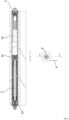
- the spring assembly (2) comprises:
- Each one of the two end assemblies comprises two coaxial portions (131, 132, 141, 142), configured to be able to rotate with respect to each other around the system rotation axis, the first one of said two portions (131, 141) being configured to rotate together with said rigid axis (15) and the second one of said two portions (132, 142) being mobile, i.e. configured to be able to rotate with respect to the rigid axis (15).
- the mobile portion (132) of said first end assembly is configured to be fastened to said tube (4) and the fixed portion (131) of said first end assembly (13) is configured to be fastened to an outer fixed support.
- the device comprises further a helical torsion spring (16), configured to be coupled to the mobile portion (132) of the first end assembly (13) and to the fixed portion (141) of the second end (14), so that when the outer tube (4) rotates, by making said mobile portion (132) rotate of the first end assembly, an end of the spring (16) rotates and the other one remains still, and the spring (16) is then subjected to a torsion deformation but, since the distance of the two end assemblies (13, 14) is constant and determined by the length of the rigid axis (15), an axial compression does not correspond to the torsion deformation.
- the spring assembly (2) comprises further a protection tube (17) configured to house the spring (16) therein.
- the protection tube (17) functions also as silencer.
- the torsion springs are subjected to a variation of their diameter after torsion. As a function of the spring turns direction and of the rotation direction, the diameter variation can increase or decrease.
- the device according to the present invention is configured so that the winding direction of the fabric on the tube and the torsion spring turns direction are such that when the fabric is lowered, and so kinetic energy is loaded in the spring, the spring diameter is reduced. For the same reason, also when the spring is preloaded in the manner described in the following, the spring diameter is reduced, and this fact increases the coupling interference between the torsion spring (16) and the two end assemblies (13, 14).
- the torsion spring (16) is coupled with interference with said ends (13, 14), and its length at rest is lower than the one of the rigid axis (15), so that, when the system is assembled, the spring (16) is subjected to an axial elastic expansion, and the strength exerted by the spring brings axially towards the centre the mobile portion (132) of said first end (13) and the fixed portion of said second end (14), thus keeping the system correctly coupled.
- the length difference between the rigid axis and the spring at rest is about 20-30% of the rigid axis length, so that the spring continues to keep the system assembled also after the rotations which it is subjected to during loading and functioning.
- the reduction of the spring length is needed to balance the axial displacement of the end portion of the spring, which, in the devices known at the state of the art, is balanced by length expansion/reduction of the torsion spring after torsion load increase and decrease during functioning.
- the end portion of the spring is always fastened to the second end assembly (14), whose distance from the first end assembly (13) is fixed by the length of the rigid axis (15) and so it is constant.
- the spring end portion has not to transmit any strength to the outer tube (4), since the mobile portion (132) of the first end assembly (13) is responsible of the torque transmission.
- ribs (1331) configured to engage respective longitudinal inner ribs provided on the surface of the tube (4), are provided. By means of the coupling of these ribs, the transmission of the torque between the spring (16) and the tube (4) occurs.
- the mobile portion (132) and the fixed portion (131) of said first end (13) are axially sliding with respect to each other between a first and a second position, limited by suitable abutting surfaces realized on said fixed (131) and mobile portion (132).
- suitable blocking means provided on both said portions (131, 132) allow their respective rotation only in one direction, while in the second position said blocking means are not engaged, and so, the respective rotation between said first and second portion is free.
- the direction the respective rotation is allowed to in the first position is the one in which the spring is loaded with kinetic energy and the diameter of its turns is reduced.
- the spring can be loaded by simply applying a respective rotation between the two fixed and mobile portions (131, 132) constituting the first end assembly (13).
- the fixed portion (13) of the first end assembly comprises grasping means (1312) provided with a polygonal print which allows its moving manually or by means of tools.
- said polygonal print is shaped and dimensioned so that it can be engaged with standard tools.
- the blocking means comprise a saw-toothed profile (1311) provided on an outer cylindrical surface of the fixed portion (131), coupled to a respective saw-toothed profile (1321) provided on the inner cylindrical surface of the mobile portion (132) of said first end assembly.
- said fixed portion (131) comprises two pieces (131-a, 131-b) integral to each other by means of connecting means, such for example a screw.
- connecting means such for example a screw.
- the pieces (131, 132) constituting the first end assembly (13) are shown in their rest position.
- the torsion spring (not shown in figure 15 ) tends in fact to bring towards the centre the mobile element (132), up to when the same abuts against the fixed element (131). In this condition, the blocking means are engaged, and the rotation is allowed only in the direction of loading the torsion spring.
- Figures 16 and 17 show instead two section views in which the mobile portion (132) is axially translated with respect to the fixed portion (13), and the blocking means are not engaged; the rotation is allowed in both the directions. This is, in particular the one of figure 16 , the system position, when in function.
- the fixed portion (131) of the first end assembly is provided with suitable fastening means (1313) configured to fasten the same to a rigid support outside the system, thus preventing the rotation of the fixed portion to this rigid support.
- suitable fastening means 1333 configured to fasten the same to a rigid support outside the system, thus preventing the rotation of the fixed portion to this rigid support.
- the torque exerted by the torsion spring is exerted between the tube (4) integral to the mobile portion (132) of the first end assembly, and so, at an end of the spring, and the outer support, fastened to the fixed portion (131) of the first end assembly, and so, by means of the central rigid axis (15), to the other end of the spring (16).
- the second end assembly (14) comprises a fixed portion (141) provided with a coupling cylindrical surface (1411) to the torsion spring and with a shaped recess (1412) for housing the rigid axis (15).
- the second end assembly comprises also a mobile portion (142), coaxially installed to said fixed portion (141) and configured to rotate freely with respect to itself.
- the mobile portion (142) acts substantially as bearing to limit friction between the inner surface of the tube (4) and the spring assembly.
- the second end assembly comprises also a fixing plug (143) configured to block the axial position of said second mobile portion (142).
- said first fixed portion (141) comprises, opposite to the rigid axis (15), fastening means (1413) to install a slowing down device (10) configured to exert a dampening action aiming at avoiding speed winding excesses.
- the spring assembly (2) is introduced at an end and the free support (3) of the other end.
- the free support (3) can be introduced in its support, and so the tube (4) can be left.
- the installation is completed by suitable blocking screws (61).
- the length of the tube (4) and supports has in fact to be configured so that the total length of the tube (4), of the portion projecting with respect to the tube of the spring assembly (2) and of the portion projecting with respect to the tube of the free support (3) is little greater than the inner length between the two rigid bearing supports (obtained in the box and integral to the window).
- the device comprises a removable blocking means (28) configured to be fastened to the projecting portion of the spring assembly (2).
- the fastening of said removable blocking means (28) occurs at the grasping means (1312) of the fixed portion (131) of the first end assembly (13).
- Said removable blocking means is configured so that the respective axial translation between the fixed portion (131) and the movable portion (132) of the first end assembly is prevented, so that it is avoided that in case of accidental compression the system passes from configuration of figure 16 , in which the system is installed and allows the fabric winding and unwinding, to configuration of figure 17 , with the risk that the support free side (14) can go out from the housing seat, with consequent bearing loss of the tube (4) and a sudden reduction of the spring assembly (2).
- the removable blocking device (28) is also configured to leave the fastening means free to the outer supports of the mobile portion (131) of the first end assembly (13). In this way, the device can be installed and left introduced and correctly functioning, with possibility of fabric winding and unwinding.
- the removal of the blocking device (28) is carried out only in case of system removal, for maintenance or substitution of the fabric (5).
Landscapes
- Engineering & Computer Science (AREA)
- Structural Engineering (AREA)
- Architecture (AREA)
- Civil Engineering (AREA)
- Paper (AREA)
- Grinding Of Cylindrical And Plane Surfaces (AREA)
- Treatment Of Liquids With Adsorbents In General (AREA)
- Operating, Guiding And Securing Of Roll- Type Closing Members (AREA)
- Springs (AREA)
Claims (9)
- Ensemble ressort (2) pour moustiquaire enroulable, store pare-soleil, volet roulant ou tout autre dispositif d'occultation enroulable autour d'un tube (4), comprenant:- un axe rigide (15), intérieur et positionné coaxialement par rapport à un ressort hélicoïdal de torsion (16), dont les extrémités sont logées à l'intérieur d'un premier (13) et d'un deuxième ensemble d'extrémité (14);- le premier (13) et le deuxième ensemble d'extrémité (14) étant positionnés aux deux extrémités dudit axe rigide (15), chacun comprenant deux parties (131, 132, 141, 142) configurées pour pouvoir tourner l'une par rapport à l'autre, chacun desdits ensembles d'extrémité (13, 14) comprenant une première partie (131, 141) desdites deux parties (131, 132, 141, 142) configurée pour tourner de manière solidaire avec ledit axe rigide (15) et une deuxième partie mobile (132, 142) desdites deux parties (131, 132, 141, 142) pouvant tourner par rapport audit axe rigide (15) ;- ladite partie mobile (132) dudit premier ensemble d'extrémité (13) étant configurée pour être fixée audit tube (4) et ladite première partie (131) dudit premier ensemble d'extrémité (13) étant configurée pour être fixée à un support extérieur;- le ressort de torsion hélicoïdal (16), couplé à la partie mobile (132) du premier ensemble d'extrémité (13) et à la première partie (141) du deuxième ensemble d'extrémité (14), de sorte que lorsque ladite partie mobile (132) du premier ensemble d'extrémité (13) tourne par rapport à ladite première partie (131) du même premier ensemble d'extrémité (13), une extrémité dudit ressort (16) tourne et l'autre reste immobile, cette rotation respective entre la partie fixe (131) et la partie mobile (132) du premier ensemble d'extrémité provoquant une accumulation d'énergie dans le ressort (16)et en ce que ledit ensemble ressort (2) comprend des moyens de blocage prévus sur lesdites parties fixe et mobile (131, 132) dudit premier ensemble d'extrémité, qui dans ladite première position permettent leur rotation respective uniquement dans un sens, tandis que dans ladite deuxième position permettent leur rotation respective dans les deux directions.
ledit ressort (16) étant configuré pour exercer une force axiale dirigée vers le centre sur ledit premier (13) et ledit deuxième ensemble d'extrémité (14) de sorte que ledit ensemble ressort (2) est caractérisé en ce que ladite partie mobile (132) et ladite partie fixe (131) dudit premier ensemble d'extrémité (13) coulissent axialement l'une par rapport à l'autre entre une première et une deuxième position, limitées par des surfaces de butée appropriées réalisées sur ladite partie fixe (131) et sur ladite partie mobile (132), - Ensemble ressort (2) pour dispositifs de protection enroulables autour d'un tube (4) selon la revendication 1, caractérisé en ce que ladite partie mobile (132) du premier ensemble d'extrémité (13) et ladite partie fixe (141) du deuxième ensemble d'extrémité (14) sont fixées de manière à ce que leur distance axiale soit constante pendant la rotation du système et déterminée par la longueur dudit axe rigide (15).
- Ensemble ressort (2) pour dispositifs de protection enroulables autour d'un tube (4) selon la revendication 1 ou 2, caractérisé en ce que la direction d'enroulement du dispositif de protection sur le tube et la direction de rotation dudit ressort (16) sont tels que lorsque le tissu est abaissé, et donc que de l'énergie cinétique est chargée dans le ressort, le diamètre du ressort est réduit.
- Ensemble ressort (2) pour dispositifs de protection enroulables autour d'un tube (4) selon l'une quelconque des revendications précédentes, caractérisé en ce que ledit ressort de torsion (16) est couplé avec interférence auxdits ensembles d'extrémité (13, 14), et sa longueur au repos est inférieure à celle de l'axe rigide (15), de sorte que, lorsque le système est assemblé, le ressort (16) est soumis à une expansion élastique axiale.
- Ensemble ressort (2) pour dispositifs de protection enroulables autour d'un tube (4) selon la revendication 5, caractérisé en ce que la direction dans laquelle la rotation respective est autorisée dans ladite première position, est celle dans laquelle le ressort est chargé d'énergie élastique et le diamètre de ses spires est réduit.
- Ensemble ressort (2) pour dispositifs de protection enroulables autour d'un tube (4) selon l'une quelconque des revendications précédentes, caractérisé en ce que ladite partie fixe (13) dudit premier ensemble d'extrémité (13) comprend des moyens de préhension (1312) permettant son déplacement manuel ou au moyen d'outils.
- Ensemble ressort (2) pour dispositifs de protection enroulables autour d'un tube (4) selon l'une quelconque des revendications 5 à 8, caractérisé en ce que lesdits moyens de blocage comprennent un profil en dents de scie (1311) prévu sur une surface cylindrique extérieure de la partie fixe (131), couplé à un profil en dents de scie respectif (1321) prévu sur une surface cylindrique intérieure de la partie mobile (132) dudit premier ensemble d'extrémité.
- Ensemble ressort (2) pour dispositifs de protection enroulables autour d'un tube (4) selon l'une quelconque des revendications précédentes, caractérisé en ce que ledit deuxième ensemble d'extrémité (14) comprend:- une partie fixe (141) pourvue d'une surface cylindrique de couplage (1411) audit ressort de torsion et d'un évidement profilé (1412) pour loger ledit axe rigide (15), et- une partie mobile (142), coaxiale à ladite partie fixe (141) et configurée pour tourner librement par rapport à elle-même.
- Dispositif de protection pour la protection de fenêtres, comprenant:- un tube (4),- un ensemble ressort (2) selon l'une quelconque des revendications précédentes et un support libre (3), introduit à partir de différentes extrémités dudit tube (4) autour duquel est enroulée la protection (5), de sorte que chacun dépasse d'une portion dudit tube, et configuré en outre pour permettre au tube (4) de reposer sur des supports fixes appropriés de sorte que le tube (4) puisse tourner autour de son propre axe, enroulant ou déroulant ainsi la protection.
Applications Claiming Priority (1)
| Application Number | Priority Date | Filing Date | Title |
|---|---|---|---|
| IT102020000015181A IT202000015181A1 (it) | 2020-06-24 | 2020-06-24 | Gruppo molla con sistema di ritenuta della carica |
Publications (3)
| Publication Number | Publication Date |
|---|---|
| EP3929397A1 EP3929397A1 (fr) | 2021-12-29 |
| EP3929397C0 EP3929397C0 (fr) | 2024-10-16 |
| EP3929397B1 true EP3929397B1 (fr) | 2024-10-16 |
Family
ID=72473770
Family Applications (1)
| Application Number | Title | Priority Date | Filing Date |
|---|---|---|---|
| EP21176054.1A Active EP3929397B1 (fr) | 2020-06-24 | 2021-05-26 | Ensemble ressort comportant un moyen de rétention de charge |
Country Status (2)
| Country | Link |
|---|---|
| EP (1) | EP3929397B1 (fr) |
| IT (1) | IT202000015181A1 (fr) |
Family Cites Families (6)
| Publication number | Priority date | Publication date | Assignee | Title |
|---|---|---|---|---|
| GB2218142B (en) * | 1988-04-11 | 1991-09-04 | Flexiform Limited | A tensioning mechanism |
| ITTO20080302A1 (it) * | 2008-04-17 | 2008-07-17 | Gianus S R L | Dispositivo di sicurezza per schermi su tubo, in particolare per tende tecniche, zanzariere, reti e schermi avvolgibili, e relativi procedimenti di installazione e disinstallazione di tale dispositivo |
| NL1039408C2 (en) * | 2012-02-27 | 2013-08-28 | Hunter Douglas Ind Bv | Roller shade. |
| JP2019531427A (ja) * | 2016-09-13 | 2019-10-31 | レイモンド ノートン,グラント | 調節可能なばねシステム及び巻上げブラインドのための方法 |
| KR20180137832A (ko) * | 2017-06-19 | 2018-12-28 | (주)한국윈텍 | 코드리스 블라인드 장치 및 코드리스 블라인드 장치의 조정방법 |
| CN109995205B (zh) | 2017-12-29 | 2020-02-28 | 北京金风科创风电设备有限公司 | 电机电枢的液体填充料浸渍后密封固化的工艺装备和方法 |
-
2020
- 2020-06-24 IT IT102020000015181A patent/IT202000015181A1/it unknown
-
2021
- 2021-05-26 EP EP21176054.1A patent/EP3929397B1/fr active Active
Also Published As
| Publication number | Publication date |
|---|---|
| IT202000015181A1 (it) | 2021-12-24 |
| EP3929397C0 (fr) | 2024-10-16 |
| EP3929397A1 (fr) | 2021-12-29 |
Similar Documents
| Publication | Publication Date | Title |
|---|---|---|
| AU2017200374B2 (en) | Window covering system and displacement controlling device thereof | |
| US4884618A (en) | Roller blind mounting and rolling system | |
| US10138676B2 (en) | Roller shade with a counterbalancing device | |
| CN108691496B (zh) | 轴结构组件、锁闭或保护装置以及装配套件 | |
| CA2139296C (fr) | Store muni d'un frein et d'une aide au relevage variables | |
| CA2599185C (fr) | Ensemble a auvent comprenant un store a ressort a defilement vers le bas | |
| EP2181233B1 (fr) | Store auto-relevable | |
| CN107299815A (zh) | 用于滚子遮阳帘的动力辅助模块 | |
| US8286685B2 (en) | Limit mechanism of upper stop level and lower stop level for rolling door | |
| US20120298317A1 (en) | Automatic roll-up device of a venetian blind | |
| KR20190094398A (ko) | 서스펜션 모듈, 서스펜션 모듈을 포함하는 전기기계식 액추에이터, 및 서스펜션 모듈 또는 전기기계식 액추에이터를 포함하는 폐쇄 또는 햇빛 차단 시스템 | |
| US20200157883A1 (en) | Adjustment mechanism for a roller blind | |
| EP3929397A1 (fr) | Ensemble ressort comportant un moyen de rétention de charge | |
| KR100770043B1 (ko) | 반자동식 롤블라인드 | |
| CZ308287B6 (cs) | Navíjecí mechanismus rolety | |
| KR102381573B1 (ko) | 전기 기계식 액추에이터 및 이러한 액추에이터를 포함하는 홈 자동화 설비 | |
| EP1925773B1 (fr) | Dispositif de réglage de tension du ressort de rappel des moustiquaires, rideaux à dérouler ou similaires | |
| GB2535506A (en) | Retractable blind system | |
| KR102030677B1 (ko) | 감속 유니트가 구비된 방충망 장치 | |
| US11230884B2 (en) | Drive system driving a screen, and apparatus comprising such a system | |
| CA1301052C (fr) | Support de store et mecanisme d'enroulement | |
| JP4832902B2 (ja) | 開閉装置の戻しばね付き巻取体構造 | |
| EP2899359B1 (fr) | Dispositif de précharge d'un ressort d'un rideau roulant | |
| EP1748146B1 (fr) | Mécanisme de freinage d'un volet roulant | |
| US20250034938A1 (en) | Roller tube assembly having adjustable torque |
Legal Events
| Date | Code | Title | Description |
|---|---|---|---|
| PUAI | Public reference made under article 153(3) epc to a published international application that has entered the european phase |
Free format text: ORIGINAL CODE: 0009012 |
|
| STAA | Information on the status of an ep patent application or granted ep patent |
Free format text: STATUS: THE APPLICATION HAS BEEN PUBLISHED |
|
| AK | Designated contracting states |
Kind code of ref document: A1 Designated state(s): AL AT BE BG CH CY CZ DE DK EE ES FI FR GB GR HR HU IE IS IT LI LT LU LV MC MK MT NL NO PL PT RO RS SE SI SK SM TR |
|
| B565 | Issuance of search results under rule 164(2) epc |
Effective date: 20211029 |
|
| STAA | Information on the status of an ep patent application or granted ep patent |
Free format text: STATUS: REQUEST FOR EXAMINATION WAS MADE |
|
| 17P | Request for examination filed |
Effective date: 20220526 |
|
| RBV | Designated contracting states (corrected) |
Designated state(s): AL AT BE BG CH CY CZ DE DK EE ES FI FR GB GR HR HU IE IS IT LI LT LU LV MC MK MT NL NO PL PT RO RS SE SI SK SM TR |
|
| GRAP | Despatch of communication of intention to grant a patent |
Free format text: ORIGINAL CODE: EPIDOSNIGR1 |
|
| STAA | Information on the status of an ep patent application or granted ep patent |
Free format text: STATUS: GRANT OF PATENT IS INTENDED |
|
| GRAS | Grant fee paid |
Free format text: ORIGINAL CODE: EPIDOSNIGR3 |
|
| INTG | Intention to grant announced |
Effective date: 20240812 |
|
| GRAA | (expected) grant |
Free format text: ORIGINAL CODE: 0009210 |
|
| STAA | Information on the status of an ep patent application or granted ep patent |
Free format text: STATUS: THE PATENT HAS BEEN GRANTED |
|
| AK | Designated contracting states |
Kind code of ref document: B1 Designated state(s): AL AT BE BG CH CY CZ DE DK EE ES FI FR GB GR HR HU IE IS IT LI LT LU LV MC MK MT NL NO PL PT RO RS SE SI SK SM TR |
|
| REG | Reference to a national code |
Ref country code: GB Ref legal event code: FG4D |
|
| REG | Reference to a national code |
Ref country code: CH Ref legal event code: EP |
|
| REG | Reference to a national code |
Ref country code: IE Ref legal event code: FG4D |
|
| REG | Reference to a national code |
Ref country code: DE Ref legal event code: R096 Ref document number: 602021020232 Country of ref document: DE |
|
| U01 | Request for unitary effect filed |
Effective date: 20241017 |
|
| U07 | Unitary effect registered |
Designated state(s): AT BE BG DE DK EE FI FR IT LT LU LV MT NL PT RO SE SI Effective date: 20241104 |
|
| PG25 | Lapsed in a contracting state [announced via postgrant information from national office to epo] |
Ref country code: IS Free format text: LAPSE BECAUSE OF FAILURE TO SUBMIT A TRANSLATION OF THE DESCRIPTION OR TO PAY THE FEE WITHIN THE PRESCRIBED TIME-LIMIT Effective date: 20250216 Ref country code: HR Free format text: LAPSE BECAUSE OF FAILURE TO SUBMIT A TRANSLATION OF THE DESCRIPTION OR TO PAY THE FEE WITHIN THE PRESCRIBED TIME-LIMIT Effective date: 20241016 |
|
| PG25 | Lapsed in a contracting state [announced via postgrant information from national office to epo] |
Ref country code: ES Free format text: LAPSE BECAUSE OF FAILURE TO SUBMIT A TRANSLATION OF THE DESCRIPTION OR TO PAY THE FEE WITHIN THE PRESCRIBED TIME-LIMIT Effective date: 20241016 |
|
| PG25 | Lapsed in a contracting state [announced via postgrant information from national office to epo] |
Ref country code: NO Free format text: LAPSE BECAUSE OF FAILURE TO SUBMIT A TRANSLATION OF THE DESCRIPTION OR TO PAY THE FEE WITHIN THE PRESCRIBED TIME-LIMIT Effective date: 20250116 |
|
| PG25 | Lapsed in a contracting state [announced via postgrant information from national office to epo] |
Ref country code: GR Free format text: LAPSE BECAUSE OF FAILURE TO SUBMIT A TRANSLATION OF THE DESCRIPTION OR TO PAY THE FEE WITHIN THE PRESCRIBED TIME-LIMIT Effective date: 20250117 |
|
| PG25 | Lapsed in a contracting state [announced via postgrant information from national office to epo] |
Ref country code: PL Free format text: LAPSE BECAUSE OF FAILURE TO SUBMIT A TRANSLATION OF THE DESCRIPTION OR TO PAY THE FEE WITHIN THE PRESCRIBED TIME-LIMIT Effective date: 20241016 |
|
| PG25 | Lapsed in a contracting state [announced via postgrant information from national office to epo] |
Ref country code: RS Free format text: LAPSE BECAUSE OF FAILURE TO SUBMIT A TRANSLATION OF THE DESCRIPTION OR TO PAY THE FEE WITHIN THE PRESCRIBED TIME-LIMIT Effective date: 20250116 |
|
| U20 | Renewal fee for the european patent with unitary effect paid |
Year of fee payment: 5 Effective date: 20250404 |
|
| PG25 | Lapsed in a contracting state [announced via postgrant information from national office to epo] |
Ref country code: SM Free format text: LAPSE BECAUSE OF FAILURE TO SUBMIT A TRANSLATION OF THE DESCRIPTION OR TO PAY THE FEE WITHIN THE PRESCRIBED TIME-LIMIT Effective date: 20241016 |
|
| PG25 | Lapsed in a contracting state [announced via postgrant information from national office to epo] |
Ref country code: SK Free format text: LAPSE BECAUSE OF FAILURE TO SUBMIT A TRANSLATION OF THE DESCRIPTION OR TO PAY THE FEE WITHIN THE PRESCRIBED TIME-LIMIT Effective date: 20241016 |
|
| PG25 | Lapsed in a contracting state [announced via postgrant information from national office to epo] |
Ref country code: CZ Free format text: LAPSE BECAUSE OF FAILURE TO SUBMIT A TRANSLATION OF THE DESCRIPTION OR TO PAY THE FEE WITHIN THE PRESCRIBED TIME-LIMIT Effective date: 20241016 |
|
| PLBE | No opposition filed within time limit |
Free format text: ORIGINAL CODE: 0009261 |
|
| STAA | Information on the status of an ep patent application or granted ep patent |
Free format text: STATUS: NO OPPOSITION FILED WITHIN TIME LIMIT |
|
| 26N | No opposition filed |
Effective date: 20250717 |
|
| REG | Reference to a national code |
Ref country code: CH Ref legal event code: H13 Free format text: ST27 STATUS EVENT CODE: U-0-0-H10-H13 (AS PROVIDED BY THE NATIONAL OFFICE) Effective date: 20251223 |
|
| PG25 | Lapsed in a contracting state [announced via postgrant information from national office to epo] |
Ref country code: CH Free format text: LAPSE BECAUSE OF NON-PAYMENT OF DUE FEES Effective date: 20250531 |
|
| GBPC | Gb: european patent ceased through non-payment of renewal fee |
Effective date: 20250526 |
|
| PG25 | Lapsed in a contracting state [announced via postgrant information from national office to epo] |
Ref country code: MC Free format text: LAPSE BECAUSE OF FAILURE TO SUBMIT A TRANSLATION OF THE DESCRIPTION OR TO PAY THE FEE WITHIN THE PRESCRIBED TIME-LIMIT Effective date: 20241016 |
|
| PG25 | Lapsed in a contracting state [announced via postgrant information from national office to epo] |
Ref country code: GB Free format text: LAPSE BECAUSE OF NON-PAYMENT OF DUE FEES Effective date: 20250526 |
|
| PG25 | Lapsed in a contracting state [announced via postgrant information from national office to epo] |
Ref country code: IE Free format text: LAPSE BECAUSE OF NON-PAYMENT OF DUE FEES Effective date: 20250526 |