EP3929007B1 - Systeme, verfahren und vorrichtungen zum greifen und transportieren von objekten - Google Patents
Systeme, verfahren und vorrichtungen zum greifen und transportieren von objekten Download PDFInfo
- Publication number
- EP3929007B1 EP3929007B1 EP21192315.6A EP21192315A EP3929007B1 EP 3929007 B1 EP3929007 B1 EP 3929007B1 EP 21192315 A EP21192315 A EP 21192315A EP 3929007 B1 EP3929007 B1 EP 3929007B1
- Authority
- EP
- European Patent Office
- Prior art keywords
- trailer
- coupled
- lifting component
- frame
- pneumatic
- Prior art date
- Legal status (The legal status is an assumption and is not a legal conclusion. Google has not performed a legal analysis and makes no representation as to the accuracy of the status listed.)
- Active
Links
- 238000000034 method Methods 0.000 title description 23
- 230000007723 transport mechanism Effects 0.000 claims description 56
- 230000008878 coupling Effects 0.000 description 109
- 238000010168 coupling process Methods 0.000 description 109
- 238000005859 coupling reaction Methods 0.000 description 109
- 230000004438 eyesight Effects 0.000 description 32
- 230000000712 assembly Effects 0.000 description 29
- 238000000429 assembly Methods 0.000 description 29
- 238000004891 communication Methods 0.000 description 17
- 230000007246 mechanism Effects 0.000 description 14
- 230000008569 process Effects 0.000 description 9
- 238000002955 isolation Methods 0.000 description 8
- 238000010586 diagram Methods 0.000 description 6
- 238000013461 design Methods 0.000 description 5
- 238000005516 engineering process Methods 0.000 description 5
- 230000001965 increasing effect Effects 0.000 description 5
- 230000036961 partial effect Effects 0.000 description 5
- 238000001514 detection method Methods 0.000 description 4
- 239000000446 fuel Substances 0.000 description 3
- 230000006870 function Effects 0.000 description 3
- 238000012544 monitoring process Methods 0.000 description 3
- 238000012545 processing Methods 0.000 description 3
- 230000000284 resting effect Effects 0.000 description 3
- 238000002485 combustion reaction Methods 0.000 description 2
- 238000004590 computer program Methods 0.000 description 2
- 230000000670 limiting effect Effects 0.000 description 2
- 230000001483 mobilizing effect Effects 0.000 description 2
- 238000012015 optical character recognition Methods 0.000 description 2
- 230000002829 reductive effect Effects 0.000 description 2
- 230000001413 cellular effect Effects 0.000 description 1
- 230000000694 effects Effects 0.000 description 1
- 230000003028 elevating effect Effects 0.000 description 1
- 230000002452 interceptive effect Effects 0.000 description 1
- 239000000463 material Substances 0.000 description 1
- 230000004297 night vision Effects 0.000 description 1
- 230000003287 optical effect Effects 0.000 description 1
- 230000037361 pathway Effects 0.000 description 1
- 239000007787 solid Substances 0.000 description 1
- 230000000007 visual effect Effects 0.000 description 1
Images


Classifications
-
- B—PERFORMING OPERATIONS; TRANSPORTING
- B60—VEHICLES IN GENERAL
- B60D—VEHICLE CONNECTIONS
- B60D1/00—Traction couplings; Hitches; Draw-gear; Towing devices
- B60D1/01—Traction couplings or hitches characterised by their type
- B60D1/07—Multi-hitch devices, i.e. comprising several hitches of the same or of a different type; Hitch-adaptors, i.e. for converting hitches from one type to another
- B60D1/075—Hitch-adaptors
-
- B—PERFORMING OPERATIONS; TRANSPORTING
- B60—VEHICLES IN GENERAL
- B60P—VEHICLES ADAPTED FOR LOAD TRANSPORTATION OR TO TRANSPORT, TO CARRY, OR TO COMPRISE SPECIAL LOADS OR OBJECTS
- B60P1/00—Vehicles predominantly for transporting loads and modified to facilitate loading, consolidating the load, or unloading
- B60P1/64—Vehicles predominantly for transporting loads and modified to facilitate loading, consolidating the load, or unloading the load supporting or containing element being readily removable
- B60P1/6418—Vehicles predominantly for transporting loads and modified to facilitate loading, consolidating the load, or unloading the load supporting or containing element being readily removable the load-transporting element being a container or similar
- B60P1/6427—Vehicles predominantly for transporting loads and modified to facilitate loading, consolidating the load, or unloading the load supporting or containing element being readily removable the load-transporting element being a container or similar the load-transporting element being shifted horizontally in a fore and aft direction, combined or not with a vertical displacement
-
- B—PERFORMING OPERATIONS; TRANSPORTING
- B60—VEHICLES IN GENERAL
- B60D—VEHICLE CONNECTIONS
- B60D1/00—Traction couplings; Hitches; Draw-gear; Towing devices
- B60D1/24—Traction couplings; Hitches; Draw-gear; Towing devices characterised by arrangements for particular functions
- B60D1/36—Traction couplings; Hitches; Draw-gear; Towing devices characterised by arrangements for particular functions for facilitating connection, e.g. hitch catchers, visual guide means, signalling aids
-
- B—PERFORMING OPERATIONS; TRANSPORTING
- B60—VEHICLES IN GENERAL
- B60D—VEHICLE CONNECTIONS
- B60D1/00—Traction couplings; Hitches; Draw-gear; Towing devices
- B60D1/58—Auxiliary devices
- B60D1/62—Auxiliary devices involving supply lines, electric circuits, or the like
-
- B—PERFORMING OPERATIONS; TRANSPORTING
- B60—VEHICLES IN GENERAL
- B60P—VEHICLES ADAPTED FOR LOAD TRANSPORTATION OR TO TRANSPORT, TO CARRY, OR TO COMPRISE SPECIAL LOADS OR OBJECTS
- B60P1/00—Vehicles predominantly for transporting loads and modified to facilitate loading, consolidating the load, or unloading
- B60P1/64—Vehicles predominantly for transporting loads and modified to facilitate loading, consolidating the load, or unloading the load supporting or containing element being readily removable
- B60P1/6418—Vehicles predominantly for transporting loads and modified to facilitate loading, consolidating the load, or unloading the load supporting or containing element being readily removable the load-transporting element being a container or similar
- B60P1/6463—Vehicles predominantly for transporting loads and modified to facilitate loading, consolidating the load, or unloading the load supporting or containing element being readily removable the load-transporting element being a container or similar fitted with articulated beams for longitudinal displacement of the container
-
- B—PERFORMING OPERATIONS; TRANSPORTING
- B60—VEHICLES IN GENERAL
- B60P—VEHICLES ADAPTED FOR LOAD TRANSPORTATION OR TO TRANSPORT, TO CARRY, OR TO COMPRISE SPECIAL LOADS OR OBJECTS
- B60P1/00—Vehicles predominantly for transporting loads and modified to facilitate loading, consolidating the load, or unloading
- B60P1/64—Vehicles predominantly for transporting loads and modified to facilitate loading, consolidating the load, or unloading the load supporting or containing element being readily removable
- B60P1/6418—Vehicles predominantly for transporting loads and modified to facilitate loading, consolidating the load, or unloading the load supporting or containing element being readily removable the load-transporting element being a container or similar
- B60P1/649—Guiding means for the load-transporting element
-
- B—PERFORMING OPERATIONS; TRANSPORTING
- B60—VEHICLES IN GENERAL
- B60P—VEHICLES ADAPTED FOR LOAD TRANSPORTATION OR TO TRANSPORT, TO CARRY, OR TO COMPRISE SPECIAL LOADS OR OBJECTS
- B60P3/00—Vehicles adapted to transport, to carry or to comprise special loads or objects
- B60P3/06—Vehicles adapted to transport, to carry or to comprise special loads or objects for carrying vehicles
-
- B—PERFORMING OPERATIONS; TRANSPORTING
- B62—LAND VEHICLES FOR TRAVELLING OTHERWISE THAN ON RAILS
- B62D—MOTOR VEHICLES; TRAILERS
- B62D53/00—Tractor-trailer combinations; Road trains
- B62D53/04—Tractor-trailer combinations; Road trains comprising a vehicle carrying an essential part of the other vehicle's load by having supporting means for the front or rear part of the other vehicle
- B62D53/06—Semi-trailers
-
- B—PERFORMING OPERATIONS; TRANSPORTING
- B62—LAND VEHICLES FOR TRAVELLING OTHERWISE THAN ON RAILS
- B62D—MOTOR VEHICLES; TRAILERS
- B62D53/00—Tractor-trailer combinations; Road trains
- B62D53/04—Tractor-trailer combinations; Road trains comprising a vehicle carrying an essential part of the other vehicle's load by having supporting means for the front or rear part of the other vehicle
- B62D53/08—Fifth wheel traction couplings
- B62D53/0857—Auxiliary semi-trailer handling or loading equipment, e.g. ramps, rigs, coupling supports
-
- B—PERFORMING OPERATIONS; TRANSPORTING
- B66—HOISTING; LIFTING; HAULING
- B66F—HOISTING, LIFTING, HAULING OR PUSHING, NOT OTHERWISE PROVIDED FOR, e.g. DEVICES WHICH APPLY A LIFTING OR PUSHING FORCE DIRECTLY TO THE SURFACE OF A LOAD
- B66F19/00—Hoisting, lifting, hauling or pushing, not otherwise provided for
-
- B—PERFORMING OPERATIONS; TRANSPORTING
- B60—VEHICLES IN GENERAL
- B60D—VEHICLE CONNECTIONS
- B60D1/00—Traction couplings; Hitches; Draw-gear; Towing devices
- B60D1/01—Traction couplings or hitches characterised by their type
- B60D1/015—Fifth wheel couplings
-
- B—PERFORMING OPERATIONS; TRANSPORTING
- B60—VEHICLES IN GENERAL
- B60P—VEHICLES ADAPTED FOR LOAD TRANSPORTATION OR TO TRANSPORT, TO CARRY, OR TO COMPRISE SPECIAL LOADS OR OBJECTS
- B60P1/00—Vehicles predominantly for transporting loads and modified to facilitate loading, consolidating the load, or unloading
- B60P1/64—Vehicles predominantly for transporting loads and modified to facilitate loading, consolidating the load, or unloading the load supporting or containing element being readily removable
- B60P1/6418—Vehicles predominantly for transporting loads and modified to facilitate loading, consolidating the load, or unloading the load supporting or containing element being readily removable the load-transporting element being a container or similar
- B60P1/6445—Vehicles predominantly for transporting loads and modified to facilitate loading, consolidating the load, or unloading the load supporting or containing element being readily removable the load-transporting element being a container or similar the load-transporting element being shifted only vertically
-
- B—PERFORMING OPERATIONS; TRANSPORTING
- B60—VEHICLES IN GENERAL
- B60T—VEHICLE BRAKE CONTROL SYSTEMS OR PARTS THEREOF; BRAKE CONTROL SYSTEMS OR PARTS THEREOF, IN GENERAL; ARRANGEMENT OF BRAKING ELEMENTS ON VEHICLES IN GENERAL; PORTABLE DEVICES FOR PREVENTING UNWANTED MOVEMENT OF VEHICLES; VEHICLE MODIFICATIONS TO FACILITATE COOLING OF BRAKES
- B60T17/00—Component parts, details, or accessories of power brake systems not covered by groups B60T8/00, B60T13/00 or B60T15/00, or presenting other characteristic features
- B60T17/04—Arrangements of piping, valves in the piping, e.g. cut-off valves, couplings or air hoses
- B60T17/043—Brake line couplings, air hoses and stopcocks
-
- B—PERFORMING OPERATIONS; TRANSPORTING
- B65—CONVEYING; PACKING; STORING; HANDLING THIN OR FILAMENTARY MATERIAL
- B65G—TRANSPORT OR STORAGE DEVICES, e.g. CONVEYORS FOR LOADING OR TIPPING, SHOP CONVEYOR SYSTEMS OR PNEUMATIC TUBE CONVEYORS
- B65G69/00—Auxiliary measures taken, or devices used, in connection with loading or unloading
- B65G69/006—Centring or aligning a vehicle at a loading station using means not being part of the vehicle
Definitions
- the field relates to systems, methods, and apparatuses for engaging and transporting objects, such as wheeled cargo trailers, or other wheeled or non-wheeled containers, vessels, and/or enclosures.
- the transportation of objects presents a number of challenges. Locating the object, identifying the object, engaging the object, adjusting/positioning/lifting the object to enable a desired level of mobility, transporting the object, and monitoring/controlling the object's position, movement, and orientation are all significant challenges. Therefore, an apparatus that provides adaptable transportation capability for objects, such as, for example, wheeled cargo trailers, is needed.
- US 3 721 358 A discloses a mobile apparatus for engaging and moving objects according to the preamble of claim 1.
- the object may be a wheeled cargo trailer or another type of wheeled or non-wheeled storage container/vessel/enclosure.
- the apparatus may be a mobile apparatus that is manually and/or autonomously controlled and operated.
- the apparatus may include a transport mechanism and a frame.
- the frame may include a base portion, any number of elongated portions, and/or any number of structural elements, sections, and/or components, as well as functional apparatuses, that are arranged to at least partially enclose an object area.
- the apparatus may include one or more lift assemblies coupled to the frame that are operable to engage an object in the object area and lift it from a lowered position to a raised position to facilitate transporting the object.
- the lift assemblies may have different configurations.
- one lift assembly may include a movable fifth wheel.
- the fifth wheel may be coupled to an actuator operable to move the fifth wheel to different positions along a length of the frame.
- the fifth wheel may also be coupled to another actuator operable to raise and lower the fifth wheel, allowing it to engage and lift a kingpin on a wheeled cargo trailer.
- a lift assembly includes separate lift components positioned on opposite sides of the frame, the lift components coupled to one or more actuators that are operable to raise and lower the lift components, extend and retract the lift components, and/or otherwise adjust the position of the lift components on the frame to facilitate engaging and lifting an object.
- a lift assembly may include one or more components adapted to engage and lift one or more wheels, tires, and/or axels or other drive train components located under an object such as a wheeled cargo trailer.
- the components of the lift assembly may be adapted and/or positioned to lift certain structures and/or portions of an object.
- a common apparatus can engage, lift, and move objects of different sizes, shapes, and/or configurations (e.g., wheeled cargo trailers of different lengths and/or having differently located lift points), providing adaptability and versatility for the moving of such objects.
- the apparatus may also include a vision system that detects objects in the surrounding environment and/or that detects a position of an object being engaged, lifted, and moved by the apparatus.
- the apparatus may include position-tracking components that determine a location of the apparatus, including its position relative to other objects.
- the apparatus may include computer processors and hardware that are configured to identify, track, and/or log detected objects, and also provide proximity-oriented feedback to ensure adequate mobility of the apparatus without interfering with or contacting other objects.
- the apparatus may further include wireless communication components that are adapted to communicate information to a central server or another computing system separate from the apparatus.
- a pneumatic adapter that can be used to provide a pneumatic connection with a pneumatically-operated braking system of a wheeled cargo trailer or container.
- the pneumatic adapter may be used to provide a standardized pneumatic connection with the braking system, and/or to provide a pneumatic connection that is an alternative to a standard braking connection, such as a glad hands connection.
- a pneumatically-operated braking system for a wheeled cargo trailer.
- the system includes, in one example aspect, a set of pneumatically-operated brakes, a glad hands connector, one or more pneumatic conduits, and the aforementioned adapter that provides a pneumatic connection with the pneumatic braking system, either through a glad hands connection or through a separate connection.
- a mobile apparatus for engaging and moving objects.
- the mobile apparatus comprises a frame with a base portion, a first elongated portion extending from the base portion, and a second elongated portion extending from the base portion, the second elongated portion being spaced from the first elongated portion.
- the mobile apparatus further comprises a first lift assembly coupled to the frame, the first lift assembly having a first lifting component and a first actuator coupled to the first lifting component, the first actuator operable to move the first lifting component to different positions along a length of the frame, and a second actuator coupled to the first lifting component and operable to move the first lifting component between a raised position and a lowered position.
- the frame further comprises a second lift assembly comprising a second lifting component, a third actuator coupled to the first elongated portion and coupled to the second lifting component and operable to move the second lifting component between a raised position and a lowered position, a third lifting component, and a fourth actuator coupled to the second elongated portion and coupled to the third lifting component and operable to move the third lifting component between a raised position and a lowered position.
- the mobile apparatus further comprises a transport mechanism coupled to the frame (fixedly or detachably) that is operable to move the frame in at least one direction.
- a mobile apparatus for engaging and moving objects comprises a frame comprising a base portion, a first elongated portion extending from the base portion, and a second elongated portion extending from the base portion, the second elongated portion spaced from the first elongated portion.
- the mobile apparatus further comprises a first lift assembly comprising a first forward lifting component coupled to a first lift actuator that is coupled to the first elongated portion, the first lift actuator operable to move the first forward lifting component between a raised position and a lowered position, and a second forward lifting component that is coupled to a second lift actuator that is coupled to the second elongated portion, the second lift actuator operable to move the second forward lifting component between a raised position and a lowered position.
- the frame further comprises a second lift assembly comprising a first rearward lifting component coupled to a third lift actuator that is coupled to the first elongated portion, the third lift actuator operable to move the first rearward lifting component between a raised position and a lowered position, and a second rearward lifting component coupled to a fourth lift actuator that is coupled to the second elongated portion, the fourth lift actuator operable to move the second rearward lifting component between a raised position and a lowered position.
- the mobile apparatus further includes a transport mechanism coupled to the frame (fixedly or detachably) that is adapted to move the frame in at least one direction.
- a pneumatically-operated braking system for a wheeled cargo trailer.
- the system comprises a set of pneumatically-operated brakes coupled to a set of wheels of the wheeled cargo trailer, a glad hands connector coupled to the wheeled cargo trailer and pneumatically coupled to the set of pneumatically-operated brakes, the glad hands connector having a first pair of pneumatic couplings, a pair of pneumatic conduits extending between the set of pneumatically operated brakes and the glad hands connector, and an adapter coupled to the wheeled cargo trailer and operable to provide a pneumatic connection with the pneumatically operated braking system.
- a method for engaging and moving a wheeled cargo trailer using a mobile apparatus comprises moving the mobile apparatus to a first position.
- the mobile apparatus includes a transport mechanism, a frame comprising a base portion coupled to the transport mechanism, a first elongated portion extending from the base portion, a second elongated portion extending from the base portion such that the second elongated portion is spaced from the first elongated portion, a first lift assembly movably coupled to the frame, and a second lift assembly coupled to the frame.
- the first position comprises a position at which the frame at least partially surrounds/encloses the wheeled cargo trailer.
- the method further comprises moving the first and second lift assemblies into respective engaging positions, moving the first lift assembly from a lowered position to a raised position using a first actuator to lift a first end of the wheeled cargo trailer, moving the second lift assembly from a lowered position to a raised position to lift a second end of the wheeled cargo trailer, and moving the wheeled cargo trailer using the transport mechanism while the wheeled cargo trailer is lifted by the frame.
- object as used herein should be interpreted broadly, to include any trailer, vehicle, container, vessel, enclosure, and/or other structure, including one of any size and shape, that can be engaged and lifted using the apparatuses and methods described herein.
- this disclosure describes systems, methods, and apparatuses for engaging, lifting, and/or moving objects, such as wheeled cargo trailers or other wheeled or non-wheeled containers/vessels/enclosures.
- wheeled cargo trailers or other wheeled or non-wheeled containers/vessels/enclosures.
- the subsequent discussion will focus on aspects of the invention in the context of a wheeled cargo trailer.
- a non-wheeled container/vessel/enclosure such as a shipping container.
- a wheeled cargo trailer is often positioned without an associated transport mechanism being attached, leaving the trailer with reduced mobility.
- the wheels of the trailer may be coupled to a pneumatic braking system that remains locked until a pneumatic source is connected to the braking system.
- Embodiments hereof enable the engaging, lifting, and/or moving of objects, such as the aforementioned wheeled cargo trailers, using various engaging, lifting, and/or mobilizing systems and components. Embodiments hereof also allow for mobilizing objects, such as wheeled cargo trailers, using pneumatically operated systems and adapters. These embodiments are described in further detail below with reference to FIGS. 1-15 .
- the subject matter of this disclosure may be provided as, at least in part, a method, a system, and/or a computer-program product, among other things. Accordingly, certain aspects disclosed herein may take the form of hardware, or may be a combination of software and hardware. A computer-program that includes computer-useable instructions embodied on one or more computer-readable media may also be used. The subject matter hereof may further be implemented as hard-coded into the mechanical design of computing components and/or may be built into a system or apparatus for engaging and moving objects.
- Computer-readable media may include volatile media, non-volatile media, removable media, and non-removable media, and may also include media readable by a database, a switch, and/or various other network devices.
- Network switches, routers, and related components are conventional in nature, as are methods of communicating with the same, and thus, further elaboration is not provided in this disclosure.
- computer-readable media may comprise computer storage media and/or non-transitory communications media.
- Computer storage media may include media implemented in any method or technology for storing information. Examples of stored information include computer-useable instructions, data structures, program modules, and/or other data representations.
- Computer storage media may include, but is not limited to, RAM, ROM, EEPROM, flash memory or other memory technology, CD-ROM, digital versatile discs (DVD), holographic media or other optical disc storage, magnetic cassettes, magnetic tape, magnetic disk storage, and other storage devices. These memory components may store data momentarily, temporarily, and/or permanently, and are not limited to the examples provided herein.
- computing device 1 suitable for enabling functions described herein is provided, in accordance with an embodiment hereof.
- computing device 1 might include multiple processors and/or multiple radios.
- computing device 1 includes a bus 9 that may directly or indirectly connect different components together, including memory 2, processor(s) 3, presentation component(s) 4 (if applicable), radio(s) 5, input/output (I/O) port(s) 6, input/output (I/O) component(s) 7, and power supply 8.
- Memory 2 may take the form of the memory components described herein. Thus, further elaboration will not be provided here, but memory 2 may include any type of tangible medium that is capable of storing information, such as a database.
- a database may include any collection of records, data, and/or other information.
- memory 2 may include a set of computer-executable instructions that, when executed, facilitate various functions or steps associated with the subject matter described herein. These instructions will be referred to as "instructions" or an "application” for short.
- the processor 3 may actually be multiple processors that may receive instructions and process them accordingly.
- the presentation component 4 may include a display, a speaker, a screen, a portable digital device, and/or other components that can present information through visual, auditory, and/or other tactile cues (e.g., a display, a screen, a lamp, a light-emitting diode (LED), a graphical user interface (GUI), and/or a lighted keyboard).
- a display e.g., a display, a screen, a lamp, a light-emitting diode (LED), a graphical user interface (GUI), and/or a lighted keyboard.
- LED light-emitting diode
- GUI graphical user interface
- the radio 5 may facilitate communication with a network, and may additionally or alternatively facilitate other types of wireless communications, such as Wi-Fi, WiMAX, LTE, Bluetooth, and/or VoIP communications, among other communication protocols.
- the radio 5 may be configured to support multiple technologies, and/or multiple radios may be configured and utilized to support multiple technologies.
- the input/output (I/O) ports 6 may take a variety of forms. Exemplary I/O ports may include a USB jack, a stereo jack, an infrared port, a firewire port, and/or other proprietary communications ports.
- the input/output (I/O) components 7 may comprise one or more keyboards, microphones, speakers, touchscreens, and/or any other item useable to directly or indirectly input data into the computing device 1.
- the power supply 8 may comprise batteries, generators, fuel cells, and/or any other component that may act as a power source to supply power to computing device 1 and to any other components described herein.
- the mobile apparatus 10 shown in FIG. 2A includes a transport mechanism 12.
- the transport mechanism 12 may take a variety of configurations between the different contemplated embodiments.
- one contemplated transport mechanism is a vehicle having one or more propulsion mechanisms, such as electric motors and batteries and/or internal combustion engines and fuel cells, and a plurality of wheels that are connected to a drive system.
- the transport mechanism 12 may be manually operated, remotely operated, and/or autonomously operated, and/or may be sized, shaped, and/or configured to provide a desired amount of mobility or adaptability for engaging objects.
- the example transport mechanism 12 shown in FIG. 2A includes a plurality of wheels 14. Some or all of the wheels 14 may be independently rotatable/steerable to provide a desired level of mobility for the mobile apparatus 10.
- any or all of the wheels may be adapted to rotate and/or be steered anywhere from +/- 0-360 degrees (e.g., in non-limiting aspects, such wheels may be adapted to rotate and/or be steered +/- 30 degrees, +/-60 degrees, +/- 90 degrees, +/- 180 degrees, or other amounts; other ranges are contemplated herein as well) to provide a desired level of maneuverability for the transport mechanism 12.
- a greater amount of wheel rotation/steerability may be provided to support operation of the transport mechanism 12 in space-constrained areas, such as a storage depot where a plurality of wheeled cargo trailers are located in relatively close proximity.
- the mobile apparatus 10 further includes a frame 16.
- the transport mechanism 12 includes a coupling mechanism 20 that is attachable to the frame 16.
- the coupling mechanism 20 may utilize pins, latches, male-female components, or other mechanical engagement elements that facilitate attachment of the transport mechanism 12 to the frame 16.
- the coupling mechanism 20 allows the transport mechanism 12 to be selectively attached to and detached from the frame 16.
- the transport mechanism 12 may simply be fixedly, pivotally, or otherwise movably secured to the frame 16 without a releasable coupling.
- the frame 16 further includes a base portion 22.
- the coupling mechanism 20 is configured such that it is attachable to the base portion 22.
- additional structures and components may be utilized to attach the transport mechanism 12 to the frame 16.
- the frame 16 includes an elongated portion 24 that is coupled to and extends from the base portion 22 and an elongated portion 26 that is coupled to and extends from the base portion 22.
- the elongated portions 24, 26 are substantially parallel and spaced apart from each other, such that the base portion 22, the elongated portion 24, and the elongated portion 26 at least partially enclose an object space 28 in which an object that is to be engaged, lifted, and moved can be positioned (e.g., a wheeled cargo trailer).
- the frame 16 further includes an elongated portion 30 coupled relative to the base portion 22 and relative to the elongated portion 24 such that it is spaced from the elongated portion 24.
- the frame 16 also includes an elongated portion 32 that is coupled relative to the base portion 22 and relative to the elongated portion 26 such that it is spaced from the elongated portion 26.
- the elongated portions 30, 32 are coupled to respective spacing members 34 and are spaced from the respective elongated portions 24, 26 by the spacing members 34.
- the elongated portions 30, 32 are also coupled to respective spacing members 36 and are spaced from each other by the spacing members 36.
- the elongated portions 24, 26, 30, 32 and the spacing members 34, 36 of the frame 16 collectively enclose and define, at least partially, the object space 28 within which an object can be positioned to be engaged, lifted, and moved.
- FIG. 2A illustrates the spacing members 34, 36 and elongated portions 24, 26, 30, 32 of the frame 16 as I-beams.
- these structural elements could have any type of cross-section (e.g., solid, hollow, round, square, rectangular, or triangular).
- the spacing members 34, 36 and elongated portions 24, 26, 30, 32 of the frame 16 collectively provide the structural strength and rigidity characteristics necessary for supporting a lifted object, such as a wheeled cargo trailer which may contain a cargo payload.
- the frame 16 may be constructed of materials, and with design characteristics, that enable it to support a particular object (e.g., of a particular size, length, width, height, weight, etc.) or load.
- the frame 16 may be sized and constructed so that it can lift and support a wheeled cargo trailer that is up to 30, 40, 50, or 60 feet long, up to 6, 8, or 10 feet wide, and/or up to 1, 2, 5, 10, 15, 20, 25, or 30 tons, for example, depending on the structural configuration. Design configurations that support other ranges are contemplated herein as well.
- the frame 16 depicted in FIG. 2A further includes a plurality of wheels 38.
- the wheels 38 are pivotally coupled to the frame 16 at respective wheel attachments 40.
- any or all of the wheels 38 and wheel attachments 40 may be configured to provide a desired level of steering/rotation (e.g., each wheel 38 may be rotatable, or steerable, anywhere in the range of +/- 0-360 degrees in various embodiments).
- Each wheel 38 may also be driven by a drive system.
- Each drive system may include a motor (e.g., an electric or internal combustion motor or a combination of the same), a steering mechanism (e.g., an electrically and/or hydraulically operated steering mechanism), and/or a power source (e.g., a generator, one or more batteries, or another power or fuel source).
- a motor e.g., an electric or internal combustion motor or a combination of the same
- a steering mechanism e.g., an electrically and/or hydraulically operated steering mechanism
- a power source e.g., a generator, one or more batteries, or another power or fuel source.
- some of the wheels 38 are fixedly attached to the frame 16 (i.e., not pivotal), and in other embodiments, only some of the wheels are driven by a drive system.
- the multi-point maneuverability of the frame 16 provided by the steerable wheels 38 and the transport mechanism 12 allows for a desired level of mobility to be provided to the mobile apparatus 10 in the x and y directions (as indicated in FIG. 2A ).
- the example mobile apparatus 10 shown in FIG. 2A includes four independently steerable wheels 38 pivotally attached to the frame 16 with respective wheel attachments 40. It is contemplated herein that with different embodiments of the mobile apparatus 10, more or fewer wheels 38 may be used.
- the frame 16 may include additional wheels, like the wheels 38 shown in FIG. 2A , coupled to the elongated portions 24, 26 of the frame 16 between the base portion 22 and an end 42 of the frame 16 that is opposite to the base portion 22.
- the mobile apparatus 10 includes a lift assembly 44 and a lift assembly 46 that are movably/adjustably coupled to the frame 16.
- the lift assemblies 44, 46 are each adapted to engage a portion of an object, such as a front portion and a rear portion of a wheeled cargo trailer, respectively, and then lift the portions of the object off of the ground, allowing the transport mechanism 12 and the frame 16 to collectively move the supported object to a desired location (e.g., without unlocking a pneumatic braking system when the object is a wheeled cargo trailer).
- the lift assemblies 44, 46 shown in FIG. 2A represent example embodiments.
- lift assemblies 44, 46 may be used to engage and lift different parts of an object (e.g., for heavier objects, more lift assemblies may be integrated into the mobile apparatus 10).
- the depictions of the lift assemblies 44, 46 shown in FIG. 2A are provided in simplified form for clarity and explanation purposes, and in implementation, such lift assemblies may include additional components (e.g., hydraulic, mechanical, and/or electric actuator components, mechanical couplings, control components, cables, hoses, indicators, interfaces, etc.).
- the lift assembly 44 is movably coupled to the base portion 22 via an actuator 56.
- the actuator 56 may be a linear actuator (e.g., a hydraulic actuator, a screw-driven actuator, and/or a belt or chain-driven actuator) that is operable to move the lift assembly 44 to different locations along a length of the frame 16, or in other words, to different distances from the base portion 22.
- the actuator 56 allows the lift assembly 44 to be positioned at a location that is suitable for engaging an object of a particular length that is located within the object space 28. Stated another way, the lift assembly 44 can be moved to different locations depending on the length of the object in the object space 28.
- the lift assembly 44 includes a base 48 and a lifting component 50 which is movably coupled to the base 48.
- the lifting component 50 is adjustable between a raised position and a lowered position using an actuator 51 coupled thereto (e.g., an electric or hydraulic linear actuator, which in FIG. 2A and 2B is partially obscured under the base 48).
- an actuator 51 coupled thereto (e.g., an electric or hydraulic linear actuator, which in FIG. 2A and 2B is partially obscured under the base 48).
- the lifting component 50 is a fifth wheel adapted to engage and lift a kingpin located on a wheeled cargo trailer. It should be noted that other types of lifting components having different engaging structures may be used with the lift assembly 44 in other aspects.
- the lift assembly 44 further includes a support frame 52 with a base 48 that is movably coupled to the elongated portions 24, 26 via a track 54 located thereon and to the elongated portions 30, 32 via a track 54 located thereon as well.
- the track 54 and base 48 may support the lifting component 50 and the support frame 52, slidably coupling them to the frame 16 and thereby allowing linear movement to be imparted to the lift assembly 44 by the actuator 56.
- the base 48 may be supported by bearings, rails, rollers, and/or other components integrated with the elongated portions 24, 26, 30, and/or 32 that provide support and/or mobility for the lift assembly 44 mounted thereon.
- the configuration of the lift assembly 44 allows the lifting component 50 to be moved to different positions along the frame 16, allowing the lifting component 50 to engage and lift objects of different lengths. Further, additional actuators, guides, tracks, and/or support structures may be used with the frame 16 to support the movement of the lift assembly 44.
- the mobile apparatus 10 and the frame 16 may include components that allow the lift assembly 44 to be locked into place at a desired location along a length of the frame 16. Such components may include locking pins, latches, and/or other mechanisms that are manually or mechanically/electrically actuated.
- the mobile apparatus 10 includes a lift assembly 46 positioned between the end 42 of the frame 16 and the lift assembly 44.
- the lift assembly 46 includes a lifting component 58 that is movably coupled to a support structure 62 coupled between the elongated portion 24 and the elongated portion 30.
- the lifting component 58 is movable between a raised position and a lowered position using an actuator 60 coupled to the lifting component 58 and to the elongated portion 24 and/or support structure 62.
- the actuator 60 is operable to move the lifting component 58 in the z-direction (as shown in FIG. 2A ) to allow for raising and lowering a portion of an object that is engaged by the lifting component 58.
- the actuator 60 which is generally obscured in FIG.
- the actuator 60 allows the lifting component 58 to move in the z-direction, as shown in FIG. 2A , adjacent the support structure 62 that extends between the elongated portions 24 and 30.
- the lift assembly 46 further includes a lifting component 64 that is movably coupled to a support structure 68 extending between the elongated portions 26, 32.
- the lifting component 64 is movable between a raised position and a lowered position using an actuator 66 coupled to the lifting component 64 and to the support structure 68 and/or second elongated portion 26.
- the actuator 66 is operable to move the lifting component 64 in the z-direction, as indicated in FIG. 2A , to allow for raising and lowering a portion of an object engaged by the lifting component 64.
- the actuator 66 similar to the actuator 60, may be positioned at least partially within the support structure 68 and/or the second elongated portion 26 and/or below the lifting component 64, and may be a linear actuator.
- the actuator 66 allows the lifting component 64 to move in the z-direction, as indicated in FIG. 2A , adjacent the support structure 68 extending between the elongated portions 26, 32.
- the lifting component 58 and the lifting component 64 of the lift assembly 46 may each be movably coupled to the frame 16 in the y-direction on their respective sides of the frame 16.
- the lifting component 58, the lift actuator 60, and the support structure 62 may all be movably coupled to the elongated portions 24, 30 via an actuator (not shown) coupled to the frame 16 (e.g., a linear actuator coupled along the elongated portion 24, which would be obscured in FIG. 2A ).
- an actuator not shown
- These components may move in unison in such actuated movement, sliding along the elongated portions 24, 30.
- the lifting component 64, the lift actuator 66, and the support structure 68 may all be movably coupled to the elongated portions 26, 32, such as via an actuator 35 coupled to the frame 16.
- an actuator (not shown) used for imparting movement of the lifting component 58, the lift actuator 60, and the support structure 62 in the y-direction, as indicated in FIG. 2A , that is mounted on the elongated portion 24 may be similar to the actuator 35 shown mounted on the elongated portion 26 in FIG. 2A .
- the actuator 35 is operable to adjust a position of the lifting component 64 in the y-direction, as indicated in FIG. 2A , along a length of the frame 16.
- the support structures 62, 68 may be, as shown in FIG. 2A , movably coupled to and supported by a track 59 that is coupled to/part of the elongated portions 30, 32 of the frame 16.
- the respective actuators e.g., 35 and/or other similar actuators
- the respective actuators used to move the lifting components 58, 64, the lift actuators 60, 66, and the support structures 62, 68 in the y-direction, as indicated in FIG. 2A , may operate independently, or the actuation and movement may be coordinated such that it occurs in unison.
- the lift assembly 44 can be repositioned at a location along the frame 16 in the y-direction that allows for engagement with and lifting of a first portion/end of the object.
- the lift assembly 46, and particularly the lifting components 58, 64 can also be moved, such as via respective actuators, in the y-direction as indicated in FIG. 2A along the frame 16 to a desired location that allows for engaging and lifting a second portion/end of the object.
- Each of the lifting components 58, 64 may further be extendably/retractably coupled to their respective support structures 62, 68 and/or elongated portions 24, 26, as shown in additional detail in the example aspects depicted in FIGS. 7A-7B and 8A-8B .
- each lifting component 58, 64 may be manually, or mechanically, extended and retracted via an actuator to allow the respective lifting component 58, 64 to be extended under or retracted from under an object (e.g., an underside of a wheeled cargo trailer). This allows the lifting components 58, 64 to be selectively moved into an engaging position where the lifting components 58, 64, when raised by the respective actuators 60, 66, engage and lift an object in the object space 28. Examples of extended and retracted positions for illustrative lifting components are shown in detail in FIGS. 7A-7B and 8A-8B .
- the mobile apparatus 10 may include a vision system.
- the vision system may comprise a selection of components at distributed locations on the mobile apparatus 10.
- one or more computer processors and/or hardware 70 may be located on the mobile apparatus 10 and communicatively connected (e.g., wirelessly and/or by wired connection) to a plurality of detectors 72 (e.g., sensors, cameras, etc., including any combination of the same) that are positioned about the mobile apparatus 10.
- the detectors 72 may be used to actively monitor the surrounding environment and/or object space 28.
- the detectors 72 may include range detection sensors, motion detection sensors, night vision sensors, thermal sensors, cameras, and/or other components that are configured to actively detect activity and/or environments around the mobile apparatus 10 or within the object space 28.
- the detectors 72 may be coupled to the transport mechanism 12 and/or to the frame 16 and may be used to guide the mobile apparatus 10 with increased precision (e.g., either manually or autonomously). Further, some of the detectors 72 may provide Light Detection and Ranging (“LIDAR”) functionality that captures object distance and spacing data. Cameras (e.g., of image and/or video type) may be used to view and monitor conditions around the mobile apparatus 10, and record images/video of the same. It should be noted that the number, location, and orientation of the detectors 72 depicted on the example mobile apparatus 10 shown in FIG. 2A represents one aspect, and more or fewer detectors, with the same or different functionality, in the same or different locations, are possible and contemplated with aspects provided herein.
- LIDAR Light Detection and Ranging
- cameras and sensors mounted on the mobile apparatus 10 may detect objects, including the identity, position, orientation, and distance of the objects, within the depot so that the mobile apparatus 10 can navigate around them.
- This information may also be recorded and/or communicated to other computing devices to facilitate surveying/monitoring an area. For example, using object recognition, position-tracking, and data logging, an accounting of objects in a particular environment (e.g., a storage depot) may be performed. In some aspects, this information may be communicated to other computing devices, such as a central server, for logging and/or processing.
- the vision system may be configured to detect text and characters through optical character recognition ("OCR").
- OCR optical character recognition
- the vision system may also be configured to perform barcode scanning, RFID reading, shape recognition, and/or other types of recognition and/or identification of objects. This detected information can be stored, used by various processing components of the mobile apparatus 10 for guidance and steering purposes, and/or communicated to other computing devices for other purposes, in example aspects.
- the computer processors and/or hardware 70 located on the mobile apparatus 10 may include components that provide wireless communication with other computing devices over a network.
- components used to facilitate wireless communication may include Bluetooth, cellular, and/or satellite communication components, or components that provide communication over other wireless communication protocols as described herein.
- the wireless communication components may be configured to share information gathered by the mobile apparatus 10 with the other computing devices to facilitate improved information management.
- the mobile apparatus 10 may also be configured with position-tracking components.
- a Global Positioning System (“GPS”) and components thereof and/or a Differential Global Positioning System (“DGPS”) and components thereof may be incorporated into the mobile apparatus 10.
- GPS Global Positioning System
- DGPS Differential Global Positioning System
- the GPS or DGPS, or another tracking system in combination with the vision system, may be used to track the position of the mobile apparatus 10 and objects observed by the mobile apparatus 10 using the vision system.
- a position-tracking system used with the mobile apparatus 10 may communicate information about the location of the mobile apparatus 10 to other computer devices via the wireless communication components and the computer processors and/or hardware 70 described above.
- components of the vision system and communication system may be positioned on an upwardly extending mast that may, in contemplated aspects, define a highest point of the transport mechanism 10.
- components of the vision system and communication system described herein may be positioned at any other location on the mobile apparatus 10 as desired.
- the vision system may be outward-looking, detecting/monitoring an environment around the mobile apparatus 10 as well as objects and characteristics thereof, and may be inward-looking, detecting a position, orientation, and/or other characteristics of an object located in the object space 28 of the mobile apparatus 10 (e.g., that is being engaged and transported).
- some of the detectors 72 on the mobile apparatus 10 e.g., including sensors and/or cameras thereof, such as those shown positioned on the lift assembly 44 and the lift assembly 46 shown in FIG. 2A , may be oriented to face inward towards the object space 28, and therefore may be used to detect a position of an object therein.
- the information obtained by these vision system components may allow the mobile apparatus 10 to maintain proper spacing from an object, reducing the incidence of collision, or improper positioning.
- the detectors 72 having inward facing components may continuously provide feedback to the one or more computer processors and/or hardware 70 for guidance purposes.
- the one or more computer processors and/or hardware 70 can process this feedback and send instructions to various components of the mobile apparatus 10 (e.g., the transport mechanism 12, including the wheels 14 thereof, and the wheels 38 of the frame 16) to control the positioning of the mobile apparatus 10 around the wheeled cargo trailer.
- This combination of active feedback and control allows the frame 16 to be positioned with increased accuracy, particularly during autonomous operation of the mobile apparatus 10.
- the lift assembly 44 of the mobile apparatus 10 depicted in FIG. 2A is provided in isolation, in accordance with an embodiment hereof.
- the lift assembly 44 includes the base 48, the lifting component 50, which in the aspect depicted in FIG. 2B is a movable fifth wheel useable for engaging a kingpin located on a wheeled cargo trailer, and the support frame 52.
- the support frame 52 as discussed with respect to FIG. 2A , can be movably coupled to the frame 16.
- the lift assembly 44 further includes a mount 53.
- the mount 53 is used for attaching the actuator 56 (shown in FIG. 2A but not in FIG. 2B ) to the lift assembly 44.
- the actuator 56 as shown in FIG. 2A , is attached to the base portion 22 at one of its ends and is attached to the lift assembly 44 via the mount 53 at the other of its ends, as shown in FIG. 2B .
- This attachment between the base portion 22 and the lift assembly 44 allows the actuator 56 to impart movement to the lift assembly 44 so that the lift assembly 44 can be repositioned along the frame 16.
- additional or alternative actuators and assemblies may be used to move the lift assembly 44 along the frame 16, and the lift assembly 44 and actuator 56 shown in FIGS. 2A-2B represent only one illustrative embodiment.
- the lifting component 50 is coupled to the actuator 51, which is partially obscured by the lifting component 50 and the base 48.
- the actuator 51 is operable to move the lifting component 50 between a raised position and a lowered position, which allows the lifting component 50 to raise and lower a portion of an object.
- the lifting component 50 is a movable fifth wheel with a kingpin engaging slot 55 that is adapted to be moved into position to engage a kingpin located on a wheeled cargo trailer.
- the actuator 51 which may be a linear actuator that extends and retracts to raise and lower the lifting component 50, is located below the fifth wheel.
- the support frame 52 at least partially supports the lift assembly 44 and an object lifted by the same.
- the support frame 52 includes track-engaging portions 74, 76 that are shaped, sized, and adapted to engage and move along the tracks 54 located on the frame 16 of the mobile apparatus 10 shown in FIG. 2A .
- the track-engaging portions 74, 76 movably attach the lift assembly 44 to the frame 16.
- FIG. 3 depicts an alternative mobile apparatus 80 adapted for engaging, lifting, and moving objects, where the mobile apparatus 80 has a different configuration of lift assemblies than the mobile apparatus 10 depicted in FIG. 2A , in accordance with an embodiment hereof.
- the mobile apparatus 80 shown in FIG. 3 includes, like the mobile apparatus 10 of FIG. 2A , a transport mechanism 12, a frame 16, and a vision system comprising computer processors and/or hardware 70 communicatively coupled to a plurality of detectors 72 (e.g., sensors and cameras), among other common components.
- the mobile apparatus 80 is also similar to the mobile apparatus 10 shown in FIG. 2A in that it includes the lift assembly 46 proximate the end of the frame 16 opposite to the base portion 22. However, the mobile apparatus 80 shown in FIG.
- the lift assembly 82 shown in FIG. 3 includes a different lift assembly 82 than the lift assembly 44 shown in FIG. 2A .
- the lift assembly 82 shown in FIG. 3 is similar to the lift assembly 46 located proximate the end of the frame 16 opposite to the base portion 22.
- the lift assembly 82 instead of providing a single lifting component 50 (e.g., a fifth wheel) with the lift assembly 44, the lift assembly 82 provides separate lifting components 84, 86 that are attached to the elongated portions 24, 26 of the frame 16, respectively, similar to the lift assembly 46.
- the lifting component 84 is movably coupled to a support structure 88 such that it is movable relative to the support structure 88 in the z-direction, as indicated in FIG. 3 .
- the support structure 88 is movably coupled to the elongated portion 24 such that it is movable relative to the elongated portion 24 in the y-direction, as indicated in FIG. 3 .
- the lifting component 84 is coupled to an actuator 90 that is operable to raise and lower the lifting component 84 relative to the support structure 88 (i.e., moving the lifting component 84 in the z-direction as indicated in FIG. 3 ).
- the lifting component 84, the support structure 88, and the actuator 90 are also movably coupled to the elongated portions 24, 30 in the y-direction, as indicated in FIG. 3 .
- the support structure 88 is movably coupled to the track 54, which is located on both elongated portions 24, 30. This allows the support structure 88, as well as the lifting component 84 and the actuator 90 coupled thereto, to move along a length of the frame 16 in the y-direction as indicated in FIG. 3 to a suitable location for lifting an object.
- the lifting component 84, the support structure 88, and the actuator 90 may be moved in the y-direction using an actuator coupled thereto (e.g., a linear actuator, such as a hydraulic, electric, or screw-driven linear actuator) that is coupled to the elongated portion 24 and actuatable in the y-direction, as indicated in FIG. 3 .
- an actuator coupled thereto e.g., a linear actuator, such as a hydraulic, electric, or screw-driven linear actuator
- the lifting component 86 is coupled to a support structure 94, which is movably coupled to the elongated portions 26, 32 of the frame 16.
- the lifting component 86 is also coupled to an actuator 92 that is operable to raise and lower the lifting component 86 in the z-direction, as indicated in FIG. 3 .
- the actuator 92 is coupled to the support structure 94 such that it is movable with the support structure 94 in the y-direction, as indicated in FIG. 3 . In this sense, for the aspect shown in FIG.
- the lifting component 86, the actuator 92, and the support structure 94 are movable together along the frame 16 in the y-direction, like the components 84, 88, 90 mounted on the opposite side.
- This movement of the lifting component 86, the actuator 92, and the support structure 94 in the y-direction may be imparted by an actuator 95 which is coupled to the elongated portion 26.
- a similar actuator and coupling assembly may be provided for the lifting component 84, the support structure 88, and the actuator 90 on the opposite side of the frame 16, in order to support imparting a similar movement to those components.
- the configuration of the lift assembly 82 shown in FIG. 3 provides different support for an object as compared to the lift assembly 44 shown in FIG. 2A (e.g., by providing support on both sides of the object).
- the operation of the lift assembly 82 shown in FIG. 3 may be manual or may be automated and/or may be guided by a vision system. It should be noted that additional lift assemblies, possibly similar to the lift assemblies 82, 46 shown in FIG. 3 , may be utilized in other embodiments, and different configurations of the lift assemblies 82, 46 are contemplated herein as well.
- FIGS. 4A-4C depict the mobile apparatus 10 shown in FIG. 2A enclosing, engaging, and lifting an object, in accordance with an embodiment hereof.
- the object in this example, is a wheeled cargo trailer 98; however, in alternative aspects, the object may be a different type of object, such as, for example, a wheel-less cargo container, vessel, and/or enclosure.
- the mobile apparatus 10 is moved into position around the trailer 98.
- the trailer 98 includes landing gear 100 located proximate a first end 102 of the trailer 98.
- the landing gear 100 is resting on the ground in FIG. 4A , supporting a forward portion of the trailer 98.
- the trailer 98 also includes a set of wheels 104 located proximate a second, rearward end 106 of the trailer 98.
- the trailer 98 may include a pneumatic braking system which, without a pneumatic connection, is engaged to prevent or restrict rotation of the wheels 104.
- FIG. 4A shows the trailer 98 remaining stationary while the frame 16 is moved into position around the trailer 98.
- the mobile apparatus 10 may utilize the vision system described herein to support automated, manual, or a combination of automated and manual steering and positioning.
- characteristics of the object e.g., size, contents, location, equipment designation, etc.
- characteristics of the object may be determined at least partially through detection of an identifier located on the object.
- an identifier may be one or more numbers and/or characters that are located and visible on the object.
- the object characteristics may be used to determine how the object should be positioned within the object space 28 enclosed by the frame 16.
- the object characteristics may also be used to determine the positions the lift components should be located in order to properly engage and lift the object.
- the frame 16 when the frame 16 is positioned around the object, the frame 16 may be positioned such that an end of the object extends past an end of the frame 16. This may be done to allow for increased access to the end of the object.
- the object is the trailer 98 shown in FIG. 4B and the trailer includes rear doors that can be opened and closed (see e.g., FIGS. 6B and 14 for one such aspect)
- the positioning of the end of the trailer past the end of the frame 16 may support increased range of motion of the doors of the trailer 98.
- this positioning of the frame 16 relative to the trailer 98 also allows the end of the trailer 98 that extends past the frame 16 to be positioned at a desired location, such as adjacent a loading dock.
- the lift assembly 44 is moved towards the rear end 42 of the frame 16 using the actuator 56 so that the lifting component 50 is located at a position at which the actuator 51 can elevate it to engage and lift the front end 102 of the trailer 98 (e.g., by engaging and lifting a kingpin located on an underside of the trailer 98).
- the lift assembly 46 can be adjusted into an extended position where the lifting components 58, 64 (not shown) are extended towards each other and under the trailer 98. Then, the lifting components 58, 64 can be raised in the z-direction as indicated in FIG. 4B using the actuators 60, 66 (shown in FIG. 2A ) to lift the rear end 106 of the trailer 98 (as shown in FIG. 4C ).
- the lifting components 58, 64 may also be moved along the respective elongated portions 24, 26 in the y-direction as indicated in FIG. 4B using respectively coupled actuators (e.g., such as the actuator 35 shown in FIG. 2A ).
- This repositioning in the y-direction may allow the lifting components 58, 64 to be positioned at a correct location for engaging an underside of the trailer 98 (e.g., a location that will not interfere with components of the trailer 98, such as lights, reflectors, hoses, etc., or a location that aligns with a designated "lift point" on the trailer 98). This positioning may also be guided by the vision system.
- the lifting component 50 of the lift assembly 44 and the lifting component 58 of the lift assembly 46 are elevated by their respective actuators 51, 60, 66, moving the trailer 98 in the z-direction as indicated in FIG. 4C to lift the landing gear 100 and the rear wheels 104 of the trailer 98 off of the ground.
- the lifting of the front and rear ends 102, 106 of the trailer 98 off of the ground allows the trailer 98 to be moved using the transport mechanism 12 and the frame 16 without interference from the brakes.
- the wheels 104 do not need to be able to roll on the ground in this lifted transport position.
- the transport mechanism 12 and the frame 16 can be used to guide the trailer 98 to a desired location, moving it in one or more directions during the process. Further, locating the trailer 98, engaging the trailer 98, lifting the trailer 98, and/or moving/steering the trailer 98 may be guided, informed, and/or controlled using the vision system described herein.
- the lift assemblies may be lifted/actuated in unison or may be lifted/actuated independently using their respective actuators.
- These lift assemblies may also lift an object at independent rates until a threshold weight, determined by a weight sensor, is detected by each lift assembly, at which time the lift assemblies may lift the object at the same rate.
- an object such as a wheeled cargo trailer
- a wheeled cargo trailer may be lifted to different contemplated heights to allow for a desired freedom of movement.
- a wheeled cargo trailer such as the trailer 98 shown in FIGS. 4A-4C
- a mobile apparatus anywhere from 1-12 inches off of the ground to provide a desired freedom of movement.
- Other lifted distances are also contemplated for the embodiments described herein.
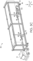
- FIGS. 5A-5C the mobile apparatus 80 depicted in FIG. 3 is shown engaging and lifting a wheeled cargo trailer 98, in accordance with the invention. Similar to the depiction in FIGS. 4A-4C , the frame 16 of the mobile apparatus 80 is guided into position around the trailer 98 using the transport mechanism 12 and/or the wheels 38 of the frame 16 and drive systems thereof. However, in contrast to the engagement and lifting of the trailer 98 by the mobile apparatus 10 as shown in FIGS. 4A-4C , the mobile apparatus 80 uses the lift assembly 82 to lift the front end 102 of the trailer 98. As discussed with respect to FIG. 3 above, the lift assemblies 46, 82 are configured with a relatively similar or common design.
- the frame 16 is propelled by the transport mechanism 12 and/or the wheels 38 of the frame 16 so that it begins enclosing the trailer 98.
- the trailer 98 enters the object space 28 from the rear end 42 of the frame 16.
- the mobile apparatus 80 is further moved and guided so that the front end 102 of the trailer 98 is proximate the base portion 22 (as shown in FIG. 3 ) of the frame 16.
- the movement of the mobile apparatus 80 may occur through manually-controlled operation and/or through autonomously-controlled operation, and may be assisted by various components and operations of the vision system described herein which may assist in maintaining proper spacing of the frame 16 from the trailer 98.
- the lift assemblies 46, 82 are positioned and/or extended as described herein for engaging and elevating the trailer 98.
- the frame 16 may be positioned so that the trailer 98 is partially enclosed within the frame 16 in the object space 28, as shown in FIG. 5B .
- the trailer 98 may be fully enclosed within the frame 16 in the object space 28 (e.g., without the end 106 extending past the frame 16).
- the partial enclosure of the trailer 98 allows the end 106 of the trailer 98 to remain exposed outside of the frame 16, increasing access to the end 106 of the trailer 98.
- This may also increase the mobility/range of movement of components located at the end 106 of the trailer 98 and/or at the end 42 of the frame 16 (e.g., such components may include trailer doors and/or retaining elements used to open and/or hold open the trailer doors, as described and shown with respect to FIGS. 6B and 14 ).
- the positioning of the end 106 of the trailer 98 past the end 42 of the frame 16 may increase accessibility to the storage area within the trailer 98, due to the fact that the trailer 98 may then be placed in relatively closer proximity to the external object without a spacing caused due to an extended section of the frame 16.
- the frame 16 may be sized such that, for a given trailer (e.g., the trailer 98), the end 106 of the trailer 98 extends at least 1, 2, 3, 4, or 5 feet past the end 42 of the frame 16, in addition to other possible distances, to allow for desired positioning and/or mobility.
- a given trailer e.g., the trailer 98
- the end 106 of the trailer 98 extends at least 1, 2, 3, 4, or 5 feet past the end 42 of the frame 16, in addition to other possible distances, to allow for desired positioning and/or mobility.
- the lifting components 58, 64, 84, 86 (some of which are obscured in FIG. 5B but are shown in FIG. 3 ) of the lift assemblies 46, 82 may be moved into desired positions along the frame 16 in the y-direction as indicated in FIG. 5B (e.g., using actuators, such as the actuator 35 shown in FIG. 2A or the actuator 95 shown in FIG. 3 ). This movement can be used to position the lifting components 58, 64, 84, 86 at suitable locations along the elongated portions 24, 26 (e.g., within the available tolerance of movement) for engaging the trailer 98.
- This movement capability of the lifting components 58, 64, 84, 86 also allows the lift assemblies 46, 82 to accommodate objects of different sizes and configurations (e.g., trailers of different lengths and/or trailers having different underside features, such as lights, reflectors, landing gear, pneumatic equipment, aerodynamic components, etc., that render certain areas not suitable for supporting the lifted trailer).
- objects of different sizes and configurations e.g., trailers of different lengths and/or trailers having different underside features, such as lights, reflectors, landing gear, pneumatic equipment, aerodynamic components, etc., that render certain areas not suitable for supporting the lifted trailer.
- each lifting component 58, 64, 84, 86 is positioned at a suitable location along the frame 16 in the y-direction as indicated in FIG. 5B , actuators respectively coupled to each lifting component 58, 64, 84, 86 may be activated (or alternatively, a manual operation may be performed) to move each of the lifting components 58, 64, 84, 86 from a retracted position to an extended position in which the respective lifting components 58, 64, 84, 86 extend further toward the object space 28, thereby reaching under the trailer 98 into a position suitable for lifting the trailer 98.
- FIG. 5B depicts non-obscured lifting components 84, 58 in the extended positions reaching, at least partially, under the trailer 98. The remaining lifting components 64, 86 are obscured by the trailer 98 in FIG. 5B but would be in a similar configuration.
- FIG. 5C depicts the mobile apparatus 80 and the trailer 98 of FIGS. 5A-5B with the lifting components 58, 64, 84, 86 (components 64 and 86 are obscured by the trailer 98 but are shown in FIG. 3 ) being raised using the actuators 60, 66, 90, 92 to an elevated position while each lifting component 58, 64, 84, 86 is in the extended position. Accordingly, as shown in FIG. 5C , each lifting component 58, 64, 84, 86 engages and lifts a respective portion of the trailer 98, lifting the landing gear 100 and the rear wheels 104 of the trailer 98 off of the ground. Once the trailer 98 is elevated to the desired height, the transport mechanism 12 and the wheels 38 of the frame 16 are used to maneuver the trailer 98 to a desired location as described herein.
- the pneumatic braking system of the trailer 98 does not need to be pressurized so that the wheels 104 can roll on the ground, and instead the trailer 98 is simply suspended and moved without using the wheels 104.
- the engaging and lifting process may be reversed to lower and deposit the trailer 98.
- the lifting components 58, 64, 84, 86 may be lowered using the respective actuators 60, 66, 90, 92, and then the lifting components 58, 64, 84, 86 may be moved from the extended position back to the retracted position, after which the mobile apparatus 80 may be moved using the transport mechanism 12 to move the frame 16 out from over the trailer 98.
- FIG. 6A a top-down plan view of the mobile apparatus 10 shown in FIG. 2A is provided, in accordance with an embodiment hereof.
- the wheels 38 may be pivotally/rotatably coupled to the frame 16 with respective wheel attachments 40.
- the wheel attachments 40 couple a respective drive system to each wheel 38 (e.g., an electric and/or hydraulic motor coupled to a steering column).
- Each wheel 38 in different contemplated aspects, may be configured to rotate, or rather be steered, up to +/- 360 degrees about its respective wheel attachment 40 in order to provide a desired degree of mobility to the mobile apparatus 10.
- each wheel 38 may be configured to provide up to 30 degrees, 45 degrees, 90 degrees, 180 degrees, or 360 degrees of rotational steering in contemplated embodiments. In some instances such as, for example, those involving a crowded storage depot with reduced space for maneuvering, a higher degree of rotation/steerability of the wheels 38 may be preferable. In further embodiments, some of the wheels 38 may have a fixed orientation.
- the lift assemblies 44 and 46 of the mobile apparatus 10 are also shown in FIG. 6A .
- the lift assembly 44 is movably coupled to the frame 16 and to the base portion 22, and is movable along a length of the frame 16 in the y-direction as indicated in FIG. 6A using the actuator 56.
- the actuator 56 is operable to move the lift assembly 44 closer to and further away from the base portion 22 by moving it along the frame 16. This movement allows the lift assembly 44 to be positioned at a suitable location for engaging a particular structure of an object being lifted (e.g., a kingpin on a trailer of a particular length, such as the trailer 98).
- the lift assembly 46 is also shown in FIG. 6A .
- the lifting component 58 of the lift assembly 46 is movably coupled to the elongated portion 24, such that it is both extendable and retractable in the x-direction (e.g., towards and away from the object space 28) as indicated in FIG. 6A .
- the lifting component 58 is also movable along the elongated portion 24 in the y-direction as indicated in FIG. 6A using an actuator 37 (which may be a linear actuator as described herein).
- the lifting component 58 is also movable between a raised position and a lowered position at least when in the extended position through operation of the actuator 60.
- the lifting component 64 is movably coupled to the elongated portion 26 and is extendable and retractable in the x-direction as indicated in FIG. 6A , or rather, towards and away from the object space 28.
- the lifting component 64 is also movable along the elongated portion 26 in the y-direction as indicated in FIG. 6A using the actuator 35 (which may, for example, be a linear actuator as described herein).
- the lifting component 64 is also movable between a raised and lowered position using the actuator 66 at least when it is in the extended position.
- FIG. 6A also depicts components of the vision system (e.g., the detectors 72) that are inward and outward facing. Such components may be placed at various locations around the frame 16, some of which are shown in FIG. 6A .
- FIG. 6B a top-down plan view of the mobile apparatus 10 depicted in FIG. 6A , with the mobile apparatus 10 moved into position around a wheeled cargo trailer 98 that is positioned adjacent a dock 110, is provided, in accordance with an embodiment hereof
- a trailer such as the trailer 98 shown in FIG. 6B
- a trailer may be located in a particular location for storage, loading, unloading, or otherwise temporarily located somewhere for certain purposes.
- a trailer may be positioned between or adjacent other trailers or objects, such as the adjacent trailers 112 shown in FIG. 6B .
- Suchadjacent trailers 98, 112 may therefore be in relatively close proximity to each other (e.g., within 1-4 feet of each other). This compact spacing/positioning may facilitate efficient use of space in a yard/depot where trailers are stored, but leaves limited space between the trailers 98, 112 for objects and equipment.
- FIG. 6B depicts how the design of the mobile apparatus 10 (and the mobile apparatus 80) allows it to be positioned around the trailer 98 and between the adjacent trailers 112 so that it can engage, lift, and move the trailer 98 using the available tolerances of movement.
- the mobile apparatus 10 is adapted to move in the x-direction and in the y-direction as indicated in FIG. 6B and rotate about the z-axis as indicated in FIG. 6B . This is accomplished using the transport mechanism 12 and wheels 14 (not shown) thereof and also the wheels 38 of the frame 16 and the drive systems thereof.
- the mobility and articulation provided by these components allows the mobile apparatus 10 to be maneuvered into position even when there are relatively small tolerances between objects, as, for example, shown in FIG. 6B .
- the transport mechanism 12 and the frame 16 may move in unison.
- the frame 16 and the transport mechanism 12 may be separable.
- the transport mechanism 12 may be attachable to the frame 16 to provide power, steering, and/or vision functionality, and/or simply may be used to assist in moving the frame 16, and possibly a lifted object, to a desired location.
- the frame 16 may then be left in place if desired, possibly with a lifted object, allowing the transport mechanism to relocate, such as to another frame and object.
- the vision system and components thereof 70, 72 coupled to the mobile apparatus 10 may be used to facilitate correct positioning of the frame 16 around the trailer 98 without contact/collision.
- the lift assemblies 44, 46 can be adjusted (e.g., in the x-direction, the y-direction, and/or the z-direction as indicated in FIG. 6B using the respectively coupled actuators discussed herein) to engage and lift the trailer 98, raising it off of the ground.
- the transport mechanism 12 can transport the trailer 98 in suspended fashion to a desired location.
- FIG. 6B further depicts a retaining mechanism 114 comprising a first-side retaining element 116 and a second-side retaining element 118, each of which is movable between a first configuration and a second configuration.
- a retaining mechanism 114 comprising a first-side retaining element 116 and a second-side retaining element 118, each of which is movable between a first configuration and a second configuration.
- each of the retaining elements 116, 118 is positioned such that it does not interfere with movement of a respective door 97, 99 of the trailer 98. This allows the doors 97, 99 of the trailer 98 to be opened and closed without interference.
- each retaining element 116, 118 is in the second configuration such that it is engaging a respective door 97, 99, as shown in FIG.
- the retaining elements 116, 118 may hold the doors 97, 99 open, restricting them from swinging during movement of the mobile apparatus 10 and trailer 98. Therefore, when the mobile apparatus 10 moves the lifted trailer 98 towards the dock 110 for loading and/or unloading or other purposes with the doors 97, 99 open, the doors 97, 99 can remain open without swinging closed due to the movement.
- the retaining elements 116, 118 may also include actuators that allow the retaining mechanism 114 to open and close the doors 97, 99 in further embodiments.
- FIGS. 7A-7B depict an example lifting component 120 of a lifting assembly, such as the lifting assembly 46 shown in FIG. 2A , useable for engaging and lifting an object, such as a wheeled cargo trailer, in accordance with an embodiment hereof.
- the lifting component 120 has an elongated shape that may facilitate load distribution.
- the lifting component 120 includes a support portion 121 which may be coupled to a frame, such as the frame 16 shown in FIGS. 2A and 3 , or to a support structure and/or actuator mounted thereon, such as the support structure 62 and actuator 60 shown in FIG. 2A . In this sense, the lifting component 120 may be mounted on an actuator adapted to raise and lower it as described herein.
- the lifting component 120 shown in FIGS. 7A-7B also includes a lifting portion 122, which is movably coupled to the support portion 121.
- the lifting portion 122 is movable between a retracted position (shown in FIG. 7A ) and an extended position (shown in FIG. 7B ).
- the retracted position may allow the lifting portion 122 to be positioned away from an area under an object
- the extended position may allow the lifting portion 122 to be positioned in the area under the object (e.g., for engaging and lifting the object).
- the lifting portion 122 is movably coupled to the support portion 121 with a pair of pivotal couplings 124, 126 that allow the lifting portion 122 to be pivoted out to the extended position.
- one or more actuators may be coupled to the pivotal couplings 124, 126 to allow the lifting portion 122 to be moved between the retracted position and the extended position in actuated fashion.
- the lifting portion 122 includes an extended planar portion 128 that provides a surface for engaging (e.g., moving into contact with) a portion of an object (e.g., an underside surface of the trailer 98).
- an example coupling structure 129 may be used to attach the lifting component 120 to a lift actuator used to raise and lower the lifting component 120, or to another structure.
- FIGS. 8A-8B depict another example lifting component 130 that can be used with a lift assembly, such as the lift assembly 46 shown in FIG. 2A , to engage and lift an object, in accordance with an embodiment hereof.
- the lifting component 130 includes a support portion 132, which may be movably coupled to a frame, such as the frame 16 shown in FIG. 2A , or to another structure using the coupling structure 129.
- the lifting component 130 also includes the lifting portion 122 and the extended planar portion 128 also provided with the lifting component 120 depicted in FIGS. 7A-7B .
- the extended planar portion 128 can be used for engaging and supporting an object when the lifting portion 122 is in the extended position.
- the lifting portion 122 of the lifting component 130 shown in FIGS. 8A-8B is not coupled to the support portion 132 with a pair of pivotal couplings that move the lifting portion 122 between the retracted position and the extended position (e.g., using a rotational actuator and control system coupled to the same).
- the lifting portion 122 of the lifting component 130 is movably coupled to the support portion 132 with a pair of linear actuators 134.
- Each of the linear actuators 134 may be electrically driven, hydraulically-driven, and/or screw-driven, among other actuation methods and mechanisms.
- the linear actuators 134 are operable to move the lifting portion 122 from the retracted position, shown in FIG. 8A , to the extended position, shown in FIG. 8B , to allow the lifting portion 122, and by association the extended planar portion 128, to reach at least partially under an object so that the lifting portion 122 can be raised using a lift actuator to lift the object.
- a lifting component and actuator assembly 138 configured to be attached to a frame and used for engaging and lifting an object, such as a wheeled cargo trailer enclosed by the frame, is provided, in accordance with an embodiment hereof.
- the assembly 138 shown in FIG. 9A includes the lifting component 120 from FIGS. 7A-7B coupled to a pair of linear actuators 136.
- the linear actuators 136 are operable to move the lifting component 120 between a raised position and a lowered position, to allow for raising and lowering an object.
- the linear actuators 136 may be operated to raise the lifting component 122 from a lowered position to a raised position and vice versa to raise and lower a portion of the object.
- the actuators 136 may be linear actuators as shown in FIG. 9A (e.g., hydraulically-driven actuators coupled to a hydraulic system), screw-driven actuators, electrically-driven actuators, belt or gear-driven actuators, and/or any other type of actuator suitable for raising and lowering the lifting component 120, like any of the other actuators described herein. Only two actuators 136 are shown in FIG. 9A for example purposes, but more or fewer actuators may be used in other embodiments.
- FIG. 9B depicts another lifting component and actuator assembly 140 that can be coupled to a frame and used for engaging and lifting an object, such as a wheeled cargo trailer, in accordance with an embodiment hereof.
- the assembly 140 shown in FIG. 9B may be coupled between portions of a frame (e.g., between the elongated portions 26, 32 of the frame 16 shown in FIG. 2A ).
- the assembly 140 includes the lifting component 120.
- the lifting component 120 includes the lifting portion 122 which is movably coupled to the support portion 121 such that it is movable between a retracted position and an extended position using the pair of pivotal couplings 124, 126 and, in certain aspects, one or more rotational actuators.
- the lifting portion 122 is shown in the extended position.
- the lifting component 120 is movably/adjustably coupled to a support member 142 that supports the lifting component 120.
- the support member 142 may enclose and/or support additional actuator components that are operable to move the lifting component 120 between the lowered position and the raised position.
- the support member 142 may at least partially contain, enclose, and/or support a piston, belt, linear-actuator, track, movable or slidable coupling, and/or other components that enable movement of the lifting component 120 up and down the support member 142.
- the support member 142 may also be fixedly or movably coupled to a frame (e.g., via a track that allows slidable movement of the support member 142 along the frame), such as the frame 16 shown in FIG. 2A .
- the support member 142 further includes example coupling portions 144 that engage with corresponding structures on a frame.
- a wheeled cargo trailer such as the trailer 98 shown in FIG. 4A
- a pneumatic braking system may include a pneumatically-powered emergency brake and a pneumatically-powered standard brake that are supplied with pressurized air through separate pneumatic conduits to unlock/control the respective brakes.
- the pressurized air for the pneumatic braking system may be provided through a glad hands connection, such as the glad hands connection 145 shown in FIG. 10A that includes pneumatic couplings 148, 150 that can be used for pneumatically attaching one or more pressurized air sources to the braking system.
- a glad hands connection such as the glad hands connection 145 shown in FIG. 10A that includes pneumatic couplings 148, 150 that can be used for pneumatically attaching one or more pressurized air sources to the braking system.
- the glad hands connection 145 shown in FIG. 10A specifically includes a pneumatic coupling 148 (e.g., for pneumatically powering an emergency brake) and a pneumatic coupling 150 (e.g., for pneumatically-powering a standard brake).
- the trailer connections 146 further includes a power/control coupling 152.
- the power/control coupling 152 allows an electrical power source to be connected to the trailer connections 146 (e.g., to power brake lights on the trailer) and also allows a control connection to be connected to the trailer connections 146 (e.g., to enable control of the brake lights on the trailer).
- FIG. 10A depicts the trailer connections 146 as it might be placed on a surface 149 of a trailer (e.g., at the first end 102 of the trailer 98 shown in FIG. 5A ).
- a pneumatic adapter such as the adapter 156 shown in FIG. 10B , may be used with the glad hands connection and/or braking system to facilitate and simplify attachment of a pressurized air source and/or power/control connection to the system.
- the adapter 156 may be mounted on the surface 149 shown in FIG. 10B and may provide, for example, pneumatic couplings that are positioned at common locations, orientations, and spacings to facilitate automated and consistent placement of connections for a pneumatic braking system.
- FIG. 10B shows the adapter 156 discussed above coupled to the trailer connections 146 shown in FIG. 10A .
- the trailer connections 146 includes the pneumatic couplings 148, 150 of the glad hands connection 145 and also the power/control coupling 152 mounted on the surface 149.
- the adapter 156 provides standardized/established locations, orientations, and spacings for its corresponding connections, as discussed further below.
- the adapter 156 includes an adapter box 158 that provides an interface with the trailer connections 146. More specifically, the adapter box 158 is connected to a pneumatic coupling 160 attached to the adapter box 158 through a pneumatic conduit 170 and is connected to a pneumatic coupling 162 attached to the adapter box 158 through a pneumatic conduit 172.
- the adapter box 158 further includes a pneumatic conduit 164 that provides a pneumatic connection between the adapter box 158 and the pneumatic coupling 148 of the glad hands connection 145 and includes a pneumatic conduit 166 that provides a pneumatic connection between the adapter box 158 and the pneumatic coupling 150 of the glad hands connection 145.
- conduits 164, 170 and the adapter box 158 pneumatically couple the pneumatic coupling 160 and the pneumatic coupling 148 of the glad hands connection 145
- conduits 166, 172 and the adapter box 158 pneumatically couple the pneumatic coupling 162 and the pneumatic coupling 150 of the glad hands connection 145.
- the pneumatic couplings 160, 162 of the adapter 156 shown in FIG. 10B are positioned on the surface 149 of the trailer at preconfigured locations, orientations, and spacings, so as to facilitate automated attachment of pressurized air sources to the pneumatic braking system (e.g., using an autonomous vehicle with correspondingly located/spaced/oriented connections).
- the adapter 156 further includes a power/control coupling 174 that is coupled to the adapter box 158 via a conduit 151.
- the power/control coupling 174 allows a power/control source to be coupled to the adapter 156 to provide power and control signals to the power/control coupling 152 of the trailer connection 146 via a power/control conduit 153.
- the pneumatic couplings 160, 162 and the power/control coupling 174 may not be attached to the adapter box 158 via the conduits 151, 170, 172, but instead may be positioned directly on the adapter box 158 or may be located on separate adapter structures.
- Other configurations and arrangements of the adapter 156 are contemplated herein.
- a corresponding mateable connection assembly that provides the pneumatic/power/control sources for the adapter 156, which may be useable by or mounted on the autonomous transport aspects discussed herein, is also contemplated.
- FIG. 10B depicts a configuration with an additional set of trailer connections 141 that are connected to the adapter box 158.
- This additional set of trailer connections 141 may or may not be included in different embodiments.
- such connections allow for a separate manual attachment configuration for the braking system, separate from the trailer connections 146.
- the trailer connections 141 include a pneumatic coupling 143 that is pneumatically connected to the adapter box 158, which provides a pneumatic connection through the pneumatic conduit 164 to the pneumatic coupling 148 of the glad hands connection 145.
- the trailer connections 141 also include a pneumatic coupling 147 that is pneumatically connected to the adapter box 158, which provides a pneumatic connection through the pneumatic conduit 166 to the pneumatic coupling 150 of the glad hands connection 145.
- the additional set of trailer connections 141 further includes a power/control coupling 157 that is coupled to the adapter box 158, which provides a power/control connection through the conduit 153 to the power/control coupling 152 of the trailer connections 146.
- the configuration shown in FIG. 10B allows the trailer connections 146 shown in FIG. 10A to remain attached to the adapter box 158 while the similarly configured trailer connection 141 is operable for manual attachment of connections that would otherwise have been connected directly to the trailer connections 146.
- This may permit a manual attachment of pneumatic and power/control connections to the braking system without having to disconnect the adapter 156 from the trailer connections 146.
- the attachment of pneumatic sources to either the pneumatic couplings 143, 147 or to the pneumatic couplings 160, 162 may occur without a release of air through the unused pneumatic couplings through use of an interlock incorporated into the adapter box 158, which is described further below with respect to FIG. 12A .
- FIG. 10C depicts a diagram of an example pneumatic braking system 176 that includes the trailer connections 146 and adapter 156 shown in FIG. 10B , in accordance with an embodiment hereof.
- the pneumatic braking system 176 is designed so that the trailer connections 146, and the glad hands connection 145 thereof, is positioned at a first location in the flow path of the pneumatic braking system 176, with the pneumatic couplings 148, 150 and the power/control coupling 152 being accessible from the first location. Further attached to the pneumatic braking system 176 at a second location is the adapter 156.
- the adapter 156 includes the pneumatic couplings 160, 162 and the power/control coupling 174 as described herein with respect to FIG. 10B .
- the adapter 156 is coupled into the flow path of the pneumatic braking system 176, as shown in FIG. 10B , providing a connection point for automated pneumatic and power/control connections.
- the location at which the adapter 156 is positioned may be a surface of a trailer, such as a surface located at the first end 102 of the trailer 98 shown in FIG. 11 .
- This positioning supports engagement with corresponding pneumatic and power/control connections located on a transport mechanism 191 shown in FIG. 10C .
- the transport mechanism 191 may be an autonomously operated transport mechanism as described herein.
- the transport mechanism 191 shown in FIG. 10C includes pneumatic couplings 190, 192 that are mateable/attachable with the pneumatic couplings 160, 162 located on the adapter 156.
- the transport mechanism 191 also includes a power/control coupling 193 that is mateable/attachable with the power/control coupling 174 located on the adapter 156.
- standardized locations, orientations, and spacings for pneumatic and power/control couplings may be provided.
- This standardized arrangement can support consistent and improved attachment of such connections, including in circumstances where the attachment is performed by an autonomous vehicle.
- the alignment and connection of the pneumatic couplings 190, 192 and the power/control coupling 193 located on the transport mechanism 191 with the pneumatic couplings 160, 162 and the power/control coupling 174 located on the adapter 156 may be facilitated using a vision system configured and used as described elsewhere herein.
- a vision system configured and used as described elsewhere herein.
- cameras, sensors, and/or processing components of the vision system may be used to detect the location of the couplings 160, 162, 174 on the trailer to support proper alignment and attachment of the couplings 190, 192, 193 to the same.
- the attachment of the couplings 190, 192, 193 to the couplings 160, 162, 174 may further be facilitated by mechanical components that are actuated and/or otherwise operated to physically attach the couplings 190, 192, 193 to the couplings 160, 162, 174.
- one or more linear actuators may be coupled to the transport mechanism 191 that are operable to move the couplings 190, 192, 193 into contact and/or engagement with the respective couplings 160, 162, 174 of the trailer connections 146.
- the couplings 190, 192, 193 may be placed at standardized (e.g., "known") locations on the transport mechanism 191 so that they correspond in location, orientation, and spacing with the couplings 160, 162, 174 of the adapter 156.
- FIG. 10C further depicts the additional set of trailer connections 141 described with respect to FIG. 10B , which are connected to the adapter 156 via the adapter box 158 thereof.
- the pneumatic coupling 143 and the pneumatic coupling 147 of the trailer connections 141 are used to provide a pneumatic connection with corresponding pneumatic couplings located on a standard tractor 180, shown in FIG. 10C .
- the power/control coupling 157 of the trailer connections 141 can also be attached to a corresponding power/control coupling located on the standard tractor 180.
- These connections may be arranged for manual attachment, or in other words, may not necessarily be arranged at standardized, established locations as with the connections on the adapter 156.
- the pneumatic isolation of the pneumatic couplings 160, 162 or the pneumatic couplings 148, 150 during use of either can be provided via the interlock 194 described below with respect to FIGS. 12A and 12B .
- FIG. 11 depicts the trailer 98 of FIG. 4A with the trailer connections 146 and adapter 156 of FIGS. 10B-10C both mounted thereon, in accordance with an embodiment hereof.
- FIG. 11 shows how the adapter 156 can be coupled into the pneumatic braking system 176 of the trailer 98 between the glad hands connection 145 and the braking connections 188, which are located adjacent the wheels 104 of the trailer 98.
- the trailer connections 146 and the adapter 156 are coupled/mounted to a surface of the trailer 98 (e.g., at the forward end 102).
- the positioning of the adapter 156 and the trailer connections 146 supports the attachment of pneumatic and power/control couplings, both from a standard tractor during normal operation (e.g., using the trailer connections 146 located on the trailer 98) and from a separate, and possibly autonomous, transport mechanism (e.g., using the adapter 156) used to shift the trailer.
- a transport mechanism 154 that has mateable components adapted to engage the adapter 156 located on the trailer 98 is shown in FIG. 13 .
- the couplings 190, 192, 193 shown in FIG. 10C may be positioned on a trailer-facing surface 155 of the transport mechanism 154 shown in FIG. 13 so that they are positioned to mateably engage with the couplings 160, 162, 174 of the adapter 156 positioned at the first end 102 of the trailer 98 as shown in FIG. 11 .
- FIGS. 12A-12B a partial, cross-section view of an interlock 194 which may be used to provide selective paths of airflow through an adapter for a pneumatic braking system, such as the adapter 156 shown in FIG. 10B , is provided, in accordance with an embodiment hereof.
- the interlock 194 in one aspect, may be located within the adapter box 158 shown in FIG. 10B , and may be configured, as shown in FIGS. 12A-12B , to allow different sets of pneumatic couplings to be used alternatively, and in isolation, to provide pressurized air to a pneumatic braking system connected to the interlock 194.
- the pneumatic couplings 143, 147 of the trailer connections 141 shown in FIG. 10B are pneumatically connected to the interlock 194, allowing standard pneumatic couplings configured for a glad hands connection, such as the glad hands connection 145 shown in FIG. 10A , to be attached to the braking system as described above (e.g., manually).
- the interlock 194 also includes the pneumatic couplings 160, 162 associated with the adapter 156 shown in FIG. 10B .
- the pneumatic couplings 160, 162 may be mounted, as described herein, at standardized locations, orientations, and spacings as described herein to support automated attachment of a pneumatic source (e.g., using an autonomous transport mechanism).
- the interlock 194 includes a pair of movable components 208A, 208B connected by a linking member 207. These movable components 208A, 208B located within the interlock 194 allow a pneumatic source to be used with either the pneumatic couplings 143, 147 in isolation or alternatively with the pneumatic couplings 160, 162 in isolation. In other words, the movable components 208A, 208B are configured to block the flow of pressurized air out of the unused pair of pneumatic couplings 143, 147 or 160, 162.
- the movable components 208A, 208B are adjustable/movable between a first position, shown in FIG. 12A , and a second position, shown in FIG. 12B .
- the first position allows a pneumatic source coupled to the pneumatic couplings 143, 147 to provide airflow through conduits 203, 205 and through junctions 209, 211, and on to an attached pneumatic braking system via conduits 213, 215, respectively.
- the pair of movable components 208A, 208B are moved in unison to block the escape of air from the pneumatic couplings 160, 162, respectively, as shown in FIG. 12A .
- the second position allows a pneumatic source coupled to the pneumatic couplings 160, 162 to provide airflow through conduits 217A, 217B and 219A, 219B and through the junctions 209, 211, and on to the pneumatic braking system through the conduits 213, 215, respectively.
- the pair of movable components 208A, 208B are moved in unison to block the escape of air from the pneumatic couplings 143, 147, respectively, as shown in FIG. 12B .
- the interlock 194 allows one set of pneumatic couplings to be used in isolation without a release of pressurized air from the unused couplings.
- the location of the movable components 208A, 208B within the interlock 194 may be controlled in different ways.
- the location may be controlled mechanically, electrically, and/or pneumatically.
- a power source may then be supplied to the interlock 194, which may initiate electrical actuation that adjusts the position of the movable components 208A, 208B (e.g., from the first position to the second position or vice versa) to provide a desired pneumatic pathway.
- This actuation may be accomplished, for example, using a solenoid.
- the location of the movable components 208A, 208B may be controlled by supplied airflow.
- a pneumatic source is attached to the interlock 194 through either set of pneumatic couplings 143, 147 or 160, 162
- a position of the movable components 208A, 208B may be adjusted or remain the same to provide a corresponding pneumatic path through the interlock 194.
- a resting, or default, configuration of the interlock 194 may be established.
- a biasing member 175 e.g., a spring as shown in FIGS.
- the interlock 194 may be incorporated into the interlock 194 so that in a resting state, in which no pneumatic sources are connected to the interlock 194, the interlock 194 remains in a desired position, such as the first position shown in FIG. 12A , to allow the desired pneumatic connections 143, 147 or 160, 162 to remain open for use. It should be noted that the default position may be the first position or the second position, as described herein.
- FIG. 13 depicts another embodiment of a mobile apparatus 212 that includes connections useable for attaching a pneumatic and/or power/control source to an adapter located on a wheeled cargo trailer as described herein, in accordance with an embodiment hereof.
- the mobile apparatus 212 includes a lift assembly 216 that is operable to lift one end of an object, such as a wheeled cargo trailer.
- the lift assembly 216 includes a movable lifting component 218 (e.g., as shown in the embodiment of FIG. 13 , a fifth wheel adapted to engage and lift a kingpin located on a trailer).
- the mobile apparatus 212 may be configured for autonomous operation and attachment to a trailer, and may further include the vision system components described herein.
- the mobile apparatus 212 shown in FIG. 13 includes the pneumatic and power/control couplings 190, 192, 193 discussed with respect to FIG. 10C . These couplings 190, 192, 193 can be aligned and engaged with corresponding couplings located on an adapter, such as the adapter 156 shown in FIG. 10C , that is mounted on a trailer as described herein. This allows the mobile apparatus 212 to connect a pneumatic and power/control source to the trailer as described with respect to FIGS. 10A-10C , in order to unlock/operate the pneumatic braking system of the trailer. The mobile apparatus 212 can then move the trailer without having to lift it to circumvent the restricted movement caused by the locked pneumatic braking system. As shown in FIG.
- the mobile apparatus 212 includes the vision components 70, 72 described herein.
- the vision system components 70, 72 may be used for guiding the mobile apparatus 212 to a desired location, locating a trailer to be engaged, and/or locating pneumatic and/or power/control couplings mounted on a trailer for engagement with the same.
- FIG. 14 a partial, rear, perspective view of a mobile apparatus 101 having a retaining mechanism 114 used for moving and/or retaining a position of doors 97, 99 located on a wheeled cargo trailer 98 is provided, in accordance with an embodiment hereof.
- the mobile apparatus 101 shown in FIG. 14 includes wheels 38 and a frame 16, and may be moved into position around the trailer 98 after which various lift assemblies (e.g., the lift assemblies 44, 46 shown in FIG. 2A ) may be used to lift the trailer 98. Once suspended, the trailer 98 may then be transported to a desired location, such as a dock 110 as shown in FIG. 6B , as described herein.
- various lift assemblies e.g., the lift assemblies 44, 46 shown in FIG. 2A
- the retaining mechanism 114 is located proximate to an end 42 of the frame 16.
- the retaining mechanism 114 includes a first-side retaining element 116 and a second-side retaining element 118 that each extend from the frame 16.
- the first-side and second-side retaining elements 116, 118 are movably coupled to the frame 16 such that they are movable to different positions.
- the first-side and second-side retaining elements 116, 118 may be securable or lockable in such positions.
- the first-side retaining element 116 is coupled to a rotational actuator 221A that is adapted to impart rotational movement to the first-side retaining element 116, and is also coupled to a linear actuator 223A that is adapted to impart linear movement to the first-side retaining element 116.
- rotational and linear actuators 221A, 223A are presented for example purposes and may or may not be incorporated, or may be incorporated differently (e.g., they may be incorporated at least partially into portions of the frame 16 such that they are obscured).
- the first-side retaining element 116 further includes a securing component 225A coupled thereto that is configured and positioned for engaging with, and securing, a door 99 located on the trailer 98.
- the second-side retaining element 118 is also coupled to a rotational actuator 221B that is adapted to impart rotational movement to the second-side retaining element 118, and is also coupled to a linear actuator 223B that is adapted to impart linear movement to the second-side retaining element 118.
- rotational and linear actuators 221B, 223B are presented for example purposes and may or may not be incorporated, or may be incorporated differently as described herein.
- the second-side retaining element 118 further includes a securing component 225B coupled thereto that is configured and positioned for engaging with, and securing, a door 97 located on the trailer 98.
- the actuators 221A, 223A and 221B, 223B shown in FIG. 14 may be used to move the first-side and second-side retaining elements 116, 118 to different extended and/or rotated positions.
- the attaching of the securing components 225A, 225B to the doors 97, 99 allows movement imparted to the first-side and second-side retaining elements 116, 118 to be imparted to the doors 97, 99, and also allows the first-side and second-side retaining elements 116, 118 to be restricted from moving when desired.
- actuators 221A, 223A and 221B, 223B are included and described for example purposes, and in alternative embodiments, these actuators may not be used, or only one may be used, or different actuators may be used.
- only the rotational actuators 221A, 221B may be incorporated, and in another embodiment, the movement of the first-side and second-side retaining elements 116, 118 may be manually enabled and controlled.
- the actuators 221A, 223A and 221B, 223B may be coupled to a control system that is operable to control the actuators and by association the movement of the first-side and second side retaining elements 116, 118.
- the retaining elements 116, 118 and actuators coupled thereto may be used to engage and move, or hold in place, the doors 97, 99 of the trailer 98.
- a control system may adjust the position of the retaining elements 116, 118 so that the securing components 225A, 225B are positioned to be coupled to the doors 97, 99.
- the doors 97, 99, once coupled with the securing components 225A, 225B, may then be moved to a desired position/orientation through operation of the actuators.
- the doors 97, 99 may also simply be held in position by the retaining elements 116, 118, such as, for example, when the trailer 98 is moved towards a loading dock with the doors 97, 99 in an open position.
- the movement and/or positioning of the retaining elements 116, 118 and the operation of any actuators coupled thereto may also be guided and/or monitored using a vision system as described herein.
- the vision system may be used to monitor the location of the doors 97, 99 and/or the location of the retaining elements 116, 118 coupled thereto.
- the doors 97, 99 may be monitored by the vision system as an extended structure of the mobile apparatus 101 so that, during movement of the mobile apparatus 101 and the trailer 98, the doors 97, 99 do not collide with surrounding objects.
- the vision system may also be used to determine where the doors 97, 99 should be positioned.
- a block diagram of an exemplary process 300 for engaging, lifting, and moving an object using a mobile apparatus is provided, in accordance with an embodiment hereof.
- a mobile apparatus such as the mobile apparatus 10 shown in FIG. 2A
- the mobile apparatus may comprise a transport mechanism, such as the transport mechanism 12 shown in FIG. 2A , and a frame, such as the frame 16 shown in FIG. 2A , comprising a base portion, such as the base portion 22 shown in FIG. 2A , coupled to the transport mechanism.
- the mobile apparatus may further include a first elongated portion, such as the elongated portion 24 shown in FIG.
- the mobile apparatus may further include a first lift assembly, such as the lift assembly 44 shown in FIG. 2A , movably coupled to the frame, and a second lift assembly, such as the lift assembly 46 shown in FIG. 2A , coupled to the frame.
- the first position may comprise a position in which the frame at least partially surrounds the wheeled cargo trailer as shown, for example, in FIG. 4B .
- a lift assembly such as the lift assembly 46
- a lifting portion 122 may be moved into an extended position through pivotal or linear actuation.
- a lifting component such as the lifting component 50 shown in FIG.
- an engaging position may comprise an adjusted position of the lifting component, such as one of the lifting components 50, 58, 64 shown in FIG. 2A , that is suitable for contacting and lifting an object enclosed by the frame.
- the movement of the lifting components into the engaging positions may occur in any of the x, y, and z directions relative to the frame, as shown in FIGS. 2A and 3 , depending on the enabled movement of the lifting components and the actuators coupled to the frame. This multi-axis movement may be facilitated using different types of actuators, such as the linear and/or rotational actuators described herein.
- the first lift assembly is moved from a lowered position to a raised position to lift a first end of the wheeled cargo trailer.
- the lifting component 50 may be elevated using the actuator 51 shown in FIG. 2A to lift the first end.
- the second lift assembly is moved from a lowered position to a raised position to lift a second end of the wheeled cargo trailer.
- the lifting components 58, 64 shown in FIG. 2A may be elevated using the linear actuators 136 shown in FIG. 9A to lift the end of the trailer. Operations described at blocks 330 and 340 may be performed simultaneously or in any sequence.
- the lifted wheeled cargo trailer is moved using the transport mechanism.
- a pneumatically-operated braking system for a wheeled cargo trailer.
- the system includes a set of pneumatically-operated brakes that are coupled to a set of wheels of the wheeled cargo trailer, a glad hands connector coupled to the wheeled cargo trailer and pneumatically coupled to the set of pneumatically-operated brakes, and an adapter coupled to the wheeled cargo trailer and operable to provide a pneumatic connection with the pneumatically-operated braking system.
- the glad hands connector has a first pair of pneumatic couplings.
- a pair of pneumatic conduits extend between the set of pneumatically-operated brakes and the glad hands connector.
- the adapter also includes a second pair of pneumatic couplings adapted to be attached to a pneumatic source and a third pair of pneumatic couplings adapted to be attached to the first pair of pneumatic couplings of the glad hands connector to provide a pneumatic connection between the adapter and the glad hands connector.
- the system further includes a pair of pneumatic conduits that are releasably attachable to the first pair of pneumatic couplings of the glad hands connector and to the third pair of pneumatic couplings of the adapter.
- the adapter may be pneumatically coupled to the pair of pneumatic conduits such that it is located between the glad hands connector and the set of pneumatically-operated brakes.
- the adapter may further include an interlock, the interlock being adjustable between a first configuration and a second configuration, the first configuration providing a pneumatic connection between the adapter and the set of brakes and the second configuration providing a pneumatic connection between the glad hands connector and the set of brakes.
- the interlock may include one or more movable components that block the pneumatic connection to the glad hands connector when the interlock is in the first configuration and block the pneumatic connection to the adapter when the interlock is in the second configuration.
- the adapter further includes a power/control coupling and a wireless communication component adapted to receive wireless signals and control, based on the received wireless signals, one or more electronic components of the wheeled cargo trailer.
- this disclosure may include the language, for example, "at least one of [element A] and [element B].” This language may refer to one or more of the elements. For example, “at least one of A and B” may refer to “A,” “B,” or “A and B.” In other words, “at least one of A and B” may refer to “at least one of A and at least one of B,” or “at least either of A or B.” In some embodiments, this disclosure may include the language, for example, “[element A], [element B], and/or [element C].” This language may refer to either of the elements or any combination thereof. In other words, “A, B, and/or C” may refer to “A,” “B,” “C,” “A and B,” “A and C,” “B and C,” or “A, B, and C.”
Claims (3)
- Mobile Vorrichtung zum Greifen und Bewegen von Objekten, wobei die mobile Vorrichtung Folgendes umfasst:
einen Rahmen (16), umfassend:einen Basisabschnitt (22),einen ersten langgestreckten Abschnitt (24), der sich von dem Basisabschnitt (22) erstreckt, undeinen zweiten langgestreckten Abschnitt (26), der sich von dem Basisabschnitt (22) erstreckt, wobei der zweite langgestreckte Abschnitt (26) von dem ersten langgestreckten Abschnitt (24) beabstandet ist;eine erste Hubbaugruppe (82), umfassend:eine erste Vorwärtshubkomponente (86), die an einen ersten Hubantrieb (92) gekoppelt ist, der an den ersten langgestreckten Abschnitt (24) gekoppelt ist, wobei der erste Hubantrieb (92) dazu betreibbar ist, die erste Vorwärtshubkomponente (86) zwischen einer angehobenen Position und einer abgesenkten Position zu bewegen, undeine zweite Vorwärtshubkomponente (84), die an einen zweiten Hubantrieb (90) gekoppelt ist, der an den zweiten langgestreckten Abschnitt (26) gekoppelt ist, wobei der zweite Hubantrieb (90) dazu betreibbar ist, die zweite Vorwärtshubkomponente (84) zwischen einer angehobenen Position und einer abgesenkten Position zu bewegen;eine zweite Hubbaugruppe (46), umfassend:eine erste Rückwärtshubkomponente (58), die an einen dritten Hubantrieb (60) gekoppelt ist, der an den ersten langgestreckten Abschnitt (24) gekoppelt ist, wobei der dritte Hubantrieb (60) dazu betreibbar ist, die erste Rückwärtshubkomponente (58) zwischen einer angehobenen Position und einer abgesenkten Position zu bewegen, undeine zweite Rückwärtshubkomponente (64), die an einen vierten Hubantrieb (66) gekoppelt ist, der an den zweiten langgestreckten Abschnitt (26) gekoppelt ist, wobei der vierte Hubantrieb (66) dazu betreibbar ist, die zweite Rückwärtshubkomponente (64) zwischen einer angehobenen Position und einer abgesenkten Position zu bewegen;einen Transportmechanismus (12), der an den Rahmen gekoppelt ist und dazu ausgelegt ist, den Rahmen (16) in mindestens einer Richtung zu bewegen;dadurch gekennzeichnet, dass die erste und die zweite Vorwärtshubkomponente (84, 86) jeweils zwischen einer eingefahrenen Position und einer ausgefahrenen Position bewegbar sind, wobei sich die erste und die zweite Vorwärtshubkomponente in der ausgefahrenen Position weiter in Richtung aufeinander erstrecken als in der eingefahrenen Position, und wobei die erste und die zweite Rückwärtshubkomponente (58, 64) jeweils zwischen einer ausgefahrenen und einer eingefahrenen Position bewegbar sind, wobei sich die erste und die zweite Rückwärtshubkomponente in der ausgefahrenen Position weiter in Richtung aufeinander erstrecken als in der eingefahrenen Position. - Mobile Vorrichtung nach Anspruch 1, wobei die erste Vorwärtshubkomponente und die erste Rückwärtshubkomponente jeweils langgestreckt sind und schwenkbar an den ersten langgestreckten Abschnitt gekoppelt sind und wobei die zweite Vorwärtshubkomponente und die zweite Rückwärtshubkomponente jeweils langgestreckt sind und schwenkbar an den zweiten langgestreckten Abschnitt gekoppelt sind, wobei die erste Vorwärtshubkomponente, die zweite Vorwärtshubkomponente, die erste Rückwärtshubkomponente und die zweite Rückwärtshubkomponente jeweils an mindestens einen Drehantrieb gekoppelt sind, der dazu betreibbar ist, die jeweilige Hubkomponente zwischen der ausgefahrenen Position und der eingefahrenen Position zu bewegen.
- Mobile Vorrichtung nach Anspruch 1, wobei die erste Vorwärtshubkomponente an einen ersten Linearantrieb gekoppelt ist, der dazu betreibbar ist, die erste Vorwärtshubkomponente an andere Stellen entlang einer Länge des ersten langgestreckten Abschnitts zu bewegen, und wobei die zweite Vorwärtshubkomponente an einen zweiten Linearantrieb gekoppelt ist, um die zweite Vorwärtshubkomponente an andere Stellen entlang einer Länge des zweiten langgestreckten Abschnitts zu bewegen, und/oder wobei die mobile Vorrichtung ferner eine Vielzahl von Rädern umfasst, wobei jedes der Räder an den Rahmen oder an den Transportmechanismus mit einem jeweiligen Radansatz gekoppelt ist, wobei zumindest einige der Vielzahl von Rädern lenkbar sind.
Applications Claiming Priority (2)
| Application Number | Priority Date | Filing Date | Title |
|---|---|---|---|
| US16/102,060 US11066000B2 (en) | 2018-08-13 | 2018-08-13 | Systems, methods, and apparatuses for engaging and transporting objects |
| EP19190503.3A EP3611042B1 (de) | 2018-08-13 | 2019-08-07 | Systeme, verfahren und vorrichtungen zum greifen und transportieren von objekten |
Related Parent Applications (2)
| Application Number | Title | Priority Date | Filing Date |
|---|---|---|---|
| EP19190503.3A Division EP3611042B1 (de) | 2018-08-13 | 2019-08-07 | Systeme, verfahren und vorrichtungen zum greifen und transportieren von objekten |
| EP19190503.3A Division-Into EP3611042B1 (de) | 2018-08-13 | 2019-08-07 | Systeme, verfahren und vorrichtungen zum greifen und transportieren von objekten |
Publications (2)
| Publication Number | Publication Date |
|---|---|
| EP3929007A1 EP3929007A1 (de) | 2021-12-29 |
| EP3929007B1 true EP3929007B1 (de) | 2023-10-04 |
Family
ID=67658520
Family Applications (3)
| Application Number | Title | Priority Date | Filing Date |
|---|---|---|---|
| EP22166386.7A Pending EP4043249A3 (de) | 2018-08-13 | 2019-08-07 | Systeme, verfahren und vorrichtungen zum greifen und transportieren von objekten |
| EP19190503.3A Active EP3611042B1 (de) | 2018-08-13 | 2019-08-07 | Systeme, verfahren und vorrichtungen zum greifen und transportieren von objekten |
| EP21192315.6A Active EP3929007B1 (de) | 2018-08-13 | 2019-08-07 | Systeme, verfahren und vorrichtungen zum greifen und transportieren von objekten |
Family Applications Before (2)
| Application Number | Title | Priority Date | Filing Date |
|---|---|---|---|
| EP22166386.7A Pending EP4043249A3 (de) | 2018-08-13 | 2019-08-07 | Systeme, verfahren und vorrichtungen zum greifen und transportieren von objekten |
| EP19190503.3A Active EP3611042B1 (de) | 2018-08-13 | 2019-08-07 | Systeme, verfahren und vorrichtungen zum greifen und transportieren von objekten |
Country Status (3)
| Country | Link |
|---|---|
| US (2) | US11066000B2 (de) |
| EP (3) | EP4043249A3 (de) |
| CA (2) | CA3152580A1 (de) |
Families Citing this family (3)
| Publication number | Priority date | Publication date | Assignee | Title |
|---|---|---|---|---|
| DE102018204442B4 (de) * | 2018-03-22 | 2021-05-27 | Zf Friedrichshafen Ag | Anhänger und Verfahren und Steuergerät zum Bestimmen einer Orientierung eines Anhängers |
| US11429106B2 (en) | 2019-09-17 | 2022-08-30 | United Parcel Service Of America, Inc. | Methods and systems for shifting objects |
| CN111559305A (zh) * | 2020-05-28 | 2020-08-21 | 盐城工学院 | 一种乘用车转运集装箱 |
Citations (1)
| Publication number | Priority date | Publication date | Assignee | Title |
|---|---|---|---|---|
| US20110268543A1 (en) * | 2008-12-02 | 2011-11-03 | James W. Welch | Container trailer |
Family Cites Families (47)
| Publication number | Priority date | Publication date | Assignee | Title |
|---|---|---|---|---|
| US3347563A (en) | 1965-10-23 | 1967-10-17 | Western Unit Corp | Fifth-wheel elevating and level controlling air jack for semi-trailer dollies |
| US3721358A (en) * | 1970-11-12 | 1973-03-20 | G Brock | Self-loading carrier |
| US3888513A (en) * | 1974-04-29 | 1975-06-10 | Young Daybrook Inc | Tractor-trailer service line coupling |
| US4077534A (en) * | 1977-02-28 | 1978-03-07 | Baaso George L | Self load/unload trailer |
| US4768802A (en) | 1986-05-22 | 1988-09-06 | The Regents Of The University Of Michigan | Controlled steering dolly for a truck trailer |
| US5098115A (en) | 1988-09-23 | 1992-03-24 | A.M. Haire Truck Bodies, Inc. | Converter dolly for permitting backing up of tandem trailers |
| US5411359A (en) | 1991-04-18 | 1995-05-02 | Liftec Products Oy | Transport trailer for lifting and moving a load and method for effecting such movements |
| FR2822422B1 (fr) * | 2001-03-21 | 2003-08-15 | Marrel Sa | Appareil de manutention d'une charge, vehicule le comportant et procede pour soulever une charge avec un tel vehicule |
| US6935829B2 (en) * | 2001-07-02 | 2005-08-30 | Smith Patents, L.L.C. | Truck operated transfer system apparatus and method |
| US20030085562A1 (en) * | 2001-11-02 | 2003-05-08 | Sparling James Douglas | Modular passenger semi-trailer with pneumatic unipoint suspension |
| US7149611B2 (en) | 2003-02-21 | 2006-12-12 | Lockheed Martin Corporation | Virtual sensor mast |
| EP1603771B1 (de) * | 2003-03-17 | 2006-09-20 | Oshkosh Truck Corporation | Drehbare und gelenkige materialhandhabungsvorrichtung |
| US7401801B2 (en) * | 2004-02-26 | 2008-07-22 | Kalmar Industires Usa, Llc | Remotely releasable coupler and hose retrieval mechanism for airbrake system |
| US7546929B2 (en) * | 2005-10-31 | 2009-06-16 | Marine Travelift, Inc. | Powered auxiliary hoist mechanism for a gantry crane |
| US20070166139A1 (en) * | 2006-01-19 | 2007-07-19 | Reed Thomas I Iii | Truck lifted rear-load transfer system |
| IL176200A (en) | 2006-06-08 | 2013-03-24 | Israel Aerospace Ind Ltd | Unmanned air vehicle system |
| ITRM20060657A1 (it) | 2006-12-06 | 2008-06-07 | Gavarini S R L | Carro semovente per la movimentazione di rimorchi e simili macchine statiche |
| FI120190B (fi) | 2007-10-25 | 2009-07-31 | Tts Liftec Oy | Järjestelmä kuorman käsittelyyn |
| US8132999B2 (en) | 2007-12-18 | 2012-03-13 | Lundin Recovery Equipment Llc | Semi trailer dolly |
| US8317452B2 (en) | 2007-12-18 | 2012-11-27 | Lundin Recovery Equipment Llc | Converter dolly for a tandem trailer |
| DE102008053538A1 (de) | 2008-10-28 | 2010-04-29 | Claas Selbstfahrende Erntemaschinen Gmbh | Dolly-Achse und diese verwendender Fahrzeugverband |
| US7866933B2 (en) | 2008-12-02 | 2011-01-11 | James W. Welch | Container trailer |
| US8534694B2 (en) * | 2009-09-30 | 2013-09-17 | Donald D. Banwart | Powered converter dolly and securing device |
| DE102009052382A1 (de) | 2009-11-09 | 2011-05-12 | Cargobeamer Ag | Verfahren und Güterumschlagterminal zum Umschlagen von Sattelaufliegern von der Schiene auf die Straße und umgekehrt sowie Zugfahrzeug für Sattelauflieger und Sattelzuggespann dafür, sowie Verfahren zum Umschlagen von Sattelaufliegern von der Schiene auf die Straße und umgekehrt und zum Transport der Sattelauflieger auf der Schiene |
| US8528929B2 (en) | 2010-01-21 | 2013-09-10 | Midwest Industrial Door, Inc. | Trailer docking repositionable support |
| US20110318148A1 (en) * | 2010-06-23 | 2011-12-29 | Obermeyer James H | Cable reeving system for lifting and loading |
| FR2963304B1 (fr) * | 2010-07-30 | 2018-02-02 | Lohr Industrie | Systeme universel de chargement/dechargement et de transport ferroviaire de semi-remorques routieres |
| DK201100052U4 (da) * | 2011-03-15 | 2012-07-13 | Pendelmatic Internat V Jan Moeller | Motorkøretøj med en batteriskiftestation |
| US8939697B2 (en) * | 2011-10-31 | 2015-01-27 | Quickthree Solutions, Inc. | Selective orientation and ballast for a transportable container |
| US8870517B2 (en) * | 2011-12-08 | 2014-10-28 | Sean Jones | Container loading and unloading system |
| WO2015038697A2 (en) | 2013-09-11 | 2015-03-19 | Silicis Technologies, Inc. | Trailer for autonomous vehicle |
| US9403470B2 (en) * | 2013-11-13 | 2016-08-02 | James H. Obermeyer | Vehicle hook hoist |
| US9168799B2 (en) * | 2014-02-03 | 2015-10-27 | Vertical Tank, Inc. | Vertical tank transport systems and related methods |
| US9771012B2 (en) * | 2014-09-04 | 2017-09-26 | Mac Trailer Manufacturing, Inc. | Roll off trailer having a stepped out front end or neck |
| US9315212B1 (en) | 2014-10-13 | 2016-04-19 | Ford Global Technologies, Llc | Trailer sensor module and associated method of wireless trailer identification and motion estimation |
| US9371133B2 (en) | 2014-11-07 | 2016-06-21 | Paccar Inc | Drone systems for pre-trip inspection and assisted backing |
| GB2533140A (en) | 2014-12-11 | 2016-06-15 | Caterpillar Inc | Drone |
| US9862297B2 (en) * | 2015-03-04 | 2018-01-09 | Selectrailers, L.L.C | Vehicle trailer system |
| US20160368336A1 (en) * | 2015-06-19 | 2016-12-22 | Paccar Inc | Use of laser scanner for autonomous truck operation |
| DE102015016672A1 (de) * | 2015-12-21 | 2017-06-22 | Bomag Gmbh | Transporteinrichtung für eine Fräseinheit, Transportfahrzeug sowie Verfahren zum Transportieren einer Fräseinheit |
| US10322874B1 (en) * | 2016-04-13 | 2019-06-18 | Mark D. Curley | Dumpster handling device and method |
| US11117741B2 (en) * | 2016-04-13 | 2021-09-14 | Mark D. Curley | Object handling device and method |
| CA2932199A1 (en) | 2016-06-07 | 2017-12-07 | Antu E. Chicahuala | Movable frame including gantry |
| US20200233410A1 (en) * | 2019-01-22 | 2020-07-23 | Proensis Llc | Electric freight trailer, system and method |
| WO2021052570A1 (en) * | 2019-09-17 | 2021-03-25 | Volvo Truck Corporation | Automatic pull tests for articulated vehicles |
| CN115052796A (zh) * | 2020-02-18 | 2022-09-13 | 沃尔沃卡车集团 | 双重挂车连接和自动检测 |
| US20240025495A1 (en) * | 2022-07-19 | 2024-01-25 | Stabilock, LLC | Shunt Truck-Dock Safety Systems |
-
2018
- 2018-08-13 US US16/102,060 patent/US11066000B2/en active Active
-
2019
- 2019-07-17 CA CA3152580A patent/CA3152580A1/en active Pending
- 2019-07-17 CA CA3050068A patent/CA3050068C/en active Active
- 2019-08-07 EP EP22166386.7A patent/EP4043249A3/de active Pending
- 2019-08-07 EP EP19190503.3A patent/EP3611042B1/de active Active
- 2019-08-07 EP EP21192315.6A patent/EP3929007B1/de active Active
-
2021
- 2021-06-22 US US17/354,592 patent/US20210316653A1/en active Pending
Patent Citations (1)
| Publication number | Priority date | Publication date | Assignee | Title |
|---|---|---|---|---|
| US20110268543A1 (en) * | 2008-12-02 | 2011-11-03 | James W. Welch | Container trailer |
Also Published As
| Publication number | Publication date |
|---|---|
| US11066000B2 (en) | 2021-07-20 |
| EP3929007A1 (de) | 2021-12-29 |
| CA3050068C (en) | 2023-03-28 |
| EP4043249A3 (de) | 2022-10-26 |
| CA3152580A1 (en) | 2020-02-13 |
| EP3611042A1 (de) | 2020-02-19 |
| US20210316653A1 (en) | 2021-10-14 |
| EP3611042B1 (de) | 2022-04-27 |
| US20200047656A1 (en) | 2020-02-13 |
| EP4043249A2 (de) | 2022-08-17 |
| CA3050068A1 (en) | 2020-02-13 |
Similar Documents
| Publication | Publication Date | Title |
|---|---|---|
| US20210316653A1 (en) | Systems, methods, and apparatuses for engaging and transporting objects | |
| EP4115491B1 (de) | Hebevorrichtung mit geteiltem batteriepack | |
| US10059450B2 (en) | Cargo handling system, method and apparatus | |
| CN112272620A (zh) | 用于自动卡车及牵引拖车的自动操作和处理的系统和方法 | |
| KR102045388B1 (ko) | 실린더 이동용 카트 | |
| WO2018211481A1 (en) | Low profile robotic pallet mover | |
| KR20210145131A (ko) | 무인 지상 기반 운송 차량 및 물품 운송 방법 | |
| EP4306340A1 (de) | Lastentransportvorrichtung | |
| US20170106880A1 (en) | Apparatus for automated transfer of large-scale missile hardware | |
| KR101685415B1 (ko) | 로봇 이동 장치 | |
| JP2023537035A (ja) | 材料搬送車、牽引機器、システム及び材料搬送車の双方向走行の制御方法 | |
| CN110667713A (zh) | 自驱物流移动平台 | |
| US11731866B2 (en) | In-ground lifting system for lifting a vehicle comprising a cover, and method for lifting a vehicle | |
| EP4317048A1 (de) | Vorrichtung zum bewegen einer nutzlast | |
| US20230073189A1 (en) | Robotic modular geologic core preparation and examination table | |
| US20240043075A1 (en) | Systems and methods for automated operation and handling of autonomous trucks and trailers hauled thereby | |
| CN211196413U (zh) | 自驱物流移动平台及其万向轮装置 | |
| US20210080968A1 (en) | Dual-mode autonomous guided vehicle | |
| EP3587179A1 (de) | Selbstfahrende maschine zum transport und zur präzisen anordnung von sperrigen gegenständen |
Legal Events
| Date | Code | Title | Description |
|---|---|---|---|
| PUAI | Public reference made under article 153(3) epc to a published international application that has entered the european phase |
Free format text: ORIGINAL CODE: 0009012 |
|
| STAA | Information on the status of an ep patent application or granted ep patent |
Free format text: STATUS: THE APPLICATION HAS BEEN PUBLISHED |
|
| AC | Divisional application: reference to earlier application |
Ref document number: 3611042 Country of ref document: EP Kind code of ref document: P |
|
| AK | Designated contracting states |
Kind code of ref document: A1 Designated state(s): AL AT BE BG CH CY CZ DE DK EE ES FI FR GB GR HR HU IE IS IT LI LT LU LV MC MK MT NL NO PL PT RO RS SE SI SK SM TR |
|
| B565 | Issuance of search results under rule 164(2) epc |
Effective date: 20211129 |
|
| STAA | Information on the status of an ep patent application or granted ep patent |
Free format text: STATUS: REQUEST FOR EXAMINATION WAS MADE |
|
| 17P | Request for examination filed |
Effective date: 20220421 |
|
| RBV | Designated contracting states (corrected) |
Designated state(s): AL AT BE BG CH CY CZ DE DK EE ES FI FR GB GR HR HU IE IS IT LI LT LU LV MC MK MT NL NO PL PT RO RS SE SI SK SM TR |
|
| GRAP | Despatch of communication of intention to grant a patent |
Free format text: ORIGINAL CODE: EPIDOSNIGR1 |
|
| STAA | Information on the status of an ep patent application or granted ep patent |
Free format text: STATUS: GRANT OF PATENT IS INTENDED |
|
| INTG | Intention to grant announced |
Effective date: 20230420 |
|
| P01 | Opt-out of the competence of the unified patent court (upc) registered |
Effective date: 20230512 |
|
| GRAS | Grant fee paid |
Free format text: ORIGINAL CODE: EPIDOSNIGR3 |
|
| GRAA | (expected) grant |
Free format text: ORIGINAL CODE: 0009210 |
|
| STAA | Information on the status of an ep patent application or granted ep patent |
Free format text: STATUS: THE PATENT HAS BEEN GRANTED |
|
| AC | Divisional application: reference to earlier application |
Ref document number: 3611042 Country of ref document: EP Kind code of ref document: P |
|
| AK | Designated contracting states |
Kind code of ref document: B1 Designated state(s): AL AT BE BG CH CY CZ DE DK EE ES FI FR GB GR HR HU IE IS IT LI LT LU LV MC MK MT NL NO PL PT RO RS SE SI SK SM TR |
|
| REG | Reference to a national code |
Ref country code: GB Ref legal event code: FG4D |
|
| REG | Reference to a national code |
Ref country code: CH Ref legal event code: EP |
|
| REG | Reference to a national code |
Ref country code: IE Ref legal event code: FG4D |
|
| REG | Reference to a national code |
Ref country code: DE Ref legal event code: R096 Ref document number: 602019038964 Country of ref document: DE |
|
| REG | Reference to a national code |
Ref country code: LT Ref legal event code: MG9D |
|
| REG | Reference to a national code |
Ref country code: NL Ref legal event code: MP Effective date: 20231004 |
|
| REG | Reference to a national code |
Ref country code: AT Ref legal event code: MK05 Ref document number: 1617411 Country of ref document: AT Kind code of ref document: T Effective date: 20231004 |
|
| PG25 | Lapsed in a contracting state [announced via postgrant information from national office to epo] |
Ref country code: NL Free format text: LAPSE BECAUSE OF FAILURE TO SUBMIT A TRANSLATION OF THE DESCRIPTION OR TO PAY THE FEE WITHIN THE PRESCRIBED TIME-LIMIT Effective date: 20231004 |
|
| PG25 | Lapsed in a contracting state [announced via postgrant information from national office to epo] |
Ref country code: GR Free format text: LAPSE BECAUSE OF FAILURE TO SUBMIT A TRANSLATION OF THE DESCRIPTION OR TO PAY THE FEE WITHIN THE PRESCRIBED TIME-LIMIT Effective date: 20240105 |
|
| PG25 | Lapsed in a contracting state [announced via postgrant information from national office to epo] |
Ref country code: IS Free format text: LAPSE BECAUSE OF FAILURE TO SUBMIT A TRANSLATION OF THE DESCRIPTION OR TO PAY THE FEE WITHIN THE PRESCRIBED TIME-LIMIT Effective date: 20240204 |
|
| PG25 | Lapsed in a contracting state [announced via postgrant information from national office to epo] |
Ref country code: LT Free format text: LAPSE BECAUSE OF FAILURE TO SUBMIT A TRANSLATION OF THE DESCRIPTION OR TO PAY THE FEE WITHIN THE PRESCRIBED TIME-LIMIT Effective date: 20231004 |
|
| PG25 | Lapsed in a contracting state [announced via postgrant information from national office to epo] |
Ref country code: AT Free format text: LAPSE BECAUSE OF FAILURE TO SUBMIT A TRANSLATION OF THE DESCRIPTION OR TO PAY THE FEE WITHIN THE PRESCRIBED TIME-LIMIT Effective date: 20231004 |
|
| PG25 | Lapsed in a contracting state [announced via postgrant information from national office to epo] |
Ref country code: ES Free format text: LAPSE BECAUSE OF FAILURE TO SUBMIT A TRANSLATION OF THE DESCRIPTION OR TO PAY THE FEE WITHIN THE PRESCRIBED TIME-LIMIT Effective date: 20231004 |
|
| PG25 | Lapsed in a contracting state [announced via postgrant information from national office to epo] |
Ref country code: LT Free format text: LAPSE BECAUSE OF FAILURE TO SUBMIT A TRANSLATION OF THE DESCRIPTION OR TO PAY THE FEE WITHIN THE PRESCRIBED TIME-LIMIT Effective date: 20231004 Ref country code: IS Free format text: LAPSE BECAUSE OF FAILURE TO SUBMIT A TRANSLATION OF THE DESCRIPTION OR TO PAY THE FEE WITHIN THE PRESCRIBED TIME-LIMIT Effective date: 20240204 Ref country code: GR Free format text: LAPSE BECAUSE OF FAILURE TO SUBMIT A TRANSLATION OF THE DESCRIPTION OR TO PAY THE FEE WITHIN THE PRESCRIBED TIME-LIMIT Effective date: 20240105 Ref country code: ES Free format text: LAPSE BECAUSE OF FAILURE TO SUBMIT A TRANSLATION OF THE DESCRIPTION OR TO PAY THE FEE WITHIN THE PRESCRIBED TIME-LIMIT Effective date: 20231004 Ref country code: BG Free format text: LAPSE BECAUSE OF FAILURE TO SUBMIT A TRANSLATION OF THE DESCRIPTION OR TO PAY THE FEE WITHIN THE PRESCRIBED TIME-LIMIT Effective date: 20240104 Ref country code: AT Free format text: LAPSE BECAUSE OF FAILURE TO SUBMIT A TRANSLATION OF THE DESCRIPTION OR TO PAY THE FEE WITHIN THE PRESCRIBED TIME-LIMIT Effective date: 20231004 Ref country code: PT Free format text: LAPSE BECAUSE OF FAILURE TO SUBMIT A TRANSLATION OF THE DESCRIPTION OR TO PAY THE FEE WITHIN THE PRESCRIBED TIME-LIMIT Effective date: 20240205 |