EP3928757B1 - Pistolengriffsystem und stosswellenrobotertherapiesystem - Google Patents
Pistolengriffsystem und stosswellenrobotertherapiesystem Download PDFInfo
- Publication number
- EP3928757B1 EP3928757B1 EP21180213.7A EP21180213A EP3928757B1 EP 3928757 B1 EP3928757 B1 EP 3928757B1 EP 21180213 A EP21180213 A EP 21180213A EP 3928757 B1 EP3928757 B1 EP 3928757B1
- Authority
- EP
- European Patent Office
- Prior art keywords
- gun handle
- shock wave
- mechanical arm
- arm
- gun
- Prior art date
- Legal status (The legal status is an assumption and is not a legal conclusion. Google has not performed a legal analysis and makes no representation as to the accuracy of the status listed.)
- Active
Links
Images



Classifications
-
- A—HUMAN NECESSITIES
- A61—MEDICAL OR VETERINARY SCIENCE; HYGIENE
- A61H—PHYSICAL THERAPY APPARATUS, e.g. DEVICES FOR LOCATING OR STIMULATING REFLEX POINTS IN THE BODY; ARTIFICIAL RESPIRATION; MASSAGE; BATHING DEVICES FOR SPECIAL THERAPEUTIC OR HYGIENIC PURPOSES OR SPECIFIC PARTS OF THE BODY
- A61H23/00—Percussion or vibration massage, e.g. using supersonic vibration; Suction-vibration massage; Massage with moving diaphragms
- A61H23/008—Percussion or vibration massage, e.g. using supersonic vibration; Suction-vibration massage; Massage with moving diaphragms using shock waves
-
- A—HUMAN NECESSITIES
- A61—MEDICAL OR VETERINARY SCIENCE; HYGIENE
- A61H—PHYSICAL THERAPY APPARATUS, e.g. DEVICES FOR LOCATING OR STIMULATING REFLEX POINTS IN THE BODY; ARTIFICIAL RESPIRATION; MASSAGE; BATHING DEVICES FOR SPECIAL THERAPEUTIC OR HYGIENIC PURPOSES OR SPECIFIC PARTS OF THE BODY
- A61H2201/00—Characteristics of apparatus not provided for in the preceding codes
- A61H2201/01—Constructive details
- A61H2201/0107—Constructive details modular
-
- A—HUMAN NECESSITIES
- A61—MEDICAL OR VETERINARY SCIENCE; HYGIENE
- A61H—PHYSICAL THERAPY APPARATUS, e.g. DEVICES FOR LOCATING OR STIMULATING REFLEX POINTS IN THE BODY; ARTIFICIAL RESPIRATION; MASSAGE; BATHING DEVICES FOR SPECIAL THERAPEUTIC OR HYGIENIC PURPOSES OR SPECIFIC PARTS OF THE BODY
- A61H2201/00—Characteristics of apparatus not provided for in the preceding codes
- A61H2201/01—Constructive details
- A61H2201/0119—Support for the device
-
- A—HUMAN NECESSITIES
- A61—MEDICAL OR VETERINARY SCIENCE; HYGIENE
- A61H—PHYSICAL THERAPY APPARATUS, e.g. DEVICES FOR LOCATING OR STIMULATING REFLEX POINTS IN THE BODY; ARTIFICIAL RESPIRATION; MASSAGE; BATHING DEVICES FOR SPECIAL THERAPEUTIC OR HYGIENIC PURPOSES OR SPECIFIC PARTS OF THE BODY
- A61H2201/00—Characteristics of apparatus not provided for in the preceding codes
- A61H2201/12—Driving means
- A61H2201/1207—Driving means with electric or magnetic drive
-
- A—HUMAN NECESSITIES
- A61—MEDICAL OR VETERINARY SCIENCE; HYGIENE
- A61H—PHYSICAL THERAPY APPARATUS, e.g. DEVICES FOR LOCATING OR STIMULATING REFLEX POINTS IN THE BODY; ARTIFICIAL RESPIRATION; MASSAGE; BATHING DEVICES FOR SPECIAL THERAPEUTIC OR HYGIENIC PURPOSES OR SPECIFIC PARTS OF THE BODY
- A61H2201/00—Characteristics of apparatus not provided for in the preceding codes
- A61H2201/12—Driving means
- A61H2201/1253—Driving means driven by a human being, e.g. hand driven
-
- A—HUMAN NECESSITIES
- A61—MEDICAL OR VETERINARY SCIENCE; HYGIENE
- A61H—PHYSICAL THERAPY APPARATUS, e.g. DEVICES FOR LOCATING OR STIMULATING REFLEX POINTS IN THE BODY; ARTIFICIAL RESPIRATION; MASSAGE; BATHING DEVICES FOR SPECIAL THERAPEUTIC OR HYGIENIC PURPOSES OR SPECIFIC PARTS OF THE BODY
- A61H2201/00—Characteristics of apparatus not provided for in the preceding codes
- A61H2201/16—Physical interface with patient
- A61H2201/1657—Movement of interface, i.e. force application means
- A61H2201/1659—Free spatial automatic movement of interface within a working area, e.g. Robot
-
- A—HUMAN NECESSITIES
- A61—MEDICAL OR VETERINARY SCIENCE; HYGIENE
- A61H—PHYSICAL THERAPY APPARATUS, e.g. DEVICES FOR LOCATING OR STIMULATING REFLEX POINTS IN THE BODY; ARTIFICIAL RESPIRATION; MASSAGE; BATHING DEVICES FOR SPECIAL THERAPEUTIC OR HYGIENIC PURPOSES OR SPECIFIC PARTS OF THE BODY
- A61H2201/00—Characteristics of apparatus not provided for in the preceding codes
- A61H2201/16—Physical interface with patient
- A61H2201/1683—Surface of interface
- A61H2201/1685—Surface of interface interchangeable
-
- A—HUMAN NECESSITIES
- A61—MEDICAL OR VETERINARY SCIENCE; HYGIENE
- A61H—PHYSICAL THERAPY APPARATUS, e.g. DEVICES FOR LOCATING OR STIMULATING REFLEX POINTS IN THE BODY; ARTIFICIAL RESPIRATION; MASSAGE; BATHING DEVICES FOR SPECIAL THERAPEUTIC OR HYGIENIC PURPOSES OR SPECIFIC PARTS OF THE BODY
- A61H2201/00—Characteristics of apparatus not provided for in the preceding codes
- A61H2201/50—Control means thereof
- A61H2201/5007—Control means thereof computer controlled
-
- A—HUMAN NECESSITIES
- A61—MEDICAL OR VETERINARY SCIENCE; HYGIENE
- A61H—PHYSICAL THERAPY APPARATUS, e.g. DEVICES FOR LOCATING OR STIMULATING REFLEX POINTS IN THE BODY; ARTIFICIAL RESPIRATION; MASSAGE; BATHING DEVICES FOR SPECIAL THERAPEUTIC OR HYGIENIC PURPOSES OR SPECIFIC PARTS OF THE BODY
- A61H2201/00—Characteristics of apparatus not provided for in the preceding codes
- A61H2201/50—Control means thereof
- A61H2201/5023—Interfaces to the user
- A61H2201/5038—Interfaces to the user freely programmable by the user
Definitions
- the embodiments of the present disclosure generally relate to the field of shock wave therapy, and more particularly relates to a gun handle system and a shock wave robot therapy system.
- the orthopedic shock wave therapy is used more and more widely in diseases such as osteoarthritis, cartilage injury, tenosynovitis and osteonecrosis (lunate necrosis, necrosis of talus and necrosis of navicular bone).
- the existing shock wave therapy system is composed of a control box or a trolley-like device, one or a plurality of gun handles, and a plurality of shock wave therapy heads.
- a doctor is required to hold a shock wave gun handle in hand to keep the end surface of the gun head in close contact with a patient's body surface for therapy.
- the mobile therapy of the shock wave gun handle on the body surface cannot be realized by adopting a passively supporting mechanical arm to hold the gun handle of the shock wave device for targeted therapy on the affected part of a patient, the doctor has to tow the mechanical arm again each time another part is switched in therapy, consuming time and labor.
- the relative position of the gun handle and a patient's body surface cannot be kept stable by holding the gun handle in a fixed position for a long time, which will affect the effective and stable transmission of shock wave energy to the treated part and thus cannot achieve an ideal therapeutic effect.
- the problem to be urgently solved at present is how to design a gun handle system which does not need to be held in hand to carry out mobile shock wave therapy and a shock wave robot therapy system.
- US 2018/236254 A1 discloses a prior art shock wave robot therapy system using a handheld applicator attached to a positioning arm.
- One purpose of the present invention is to provide a gun handle system.
- the other purpose of the present invention is to provide a shock wave robot therapy system comprising the gun handle system.
- the embodiments of the first aspect of the present invention provide a gun handle system which is used for a shock wave robot therapy system, wherein the shock wave robot therapy system comprises a host and a gun handle system installed on the host, the gun handle system can move under the action of the host, and the gun handle system comprises:
- a recording device which can record the motion track of the mechanical arm is arranged in the mechanical arm or the host.
- the gun handle system also comprises a visual acquisition device installed on the mechanical arm or the gun handle, wherein the visual acquisition device is used for collecting image information about a patient's body surface.
- the mechanical arm is a seven-degree-of-freedom flexible mechanical arm.
- the gun handle system also comprises a coupling component which is installed on the gun head, and the gun head is in contact with a patient's body surface through the coupling component in the therapeutic process.
- the gun handle also comprises a housing in which the shock wave generator is installed, wherein the front end of the gun handle extends out of the housing; and a silencing shock absorption pipe which is installed in the housing and sheathed on the shock wave generator.
- the housing comprises a base and a shell installed on the base, an installation cavity is formed between the shell and the base, the base is provided with a through hole communicating with the installation cavity, and the base can be detachably connected with the end-of-arm tooling connector;
- the gun handle also comprises: a power source control device which is used for controlling a shock wave power source to be on and off, installed in the housing and provided with an accommodating cavity, wherein the accommodating cavity is provided with an opening at one end close to the base, one end of the shock wave generator is installed in the accommodating cavity, and the other end of the shock wave generator penetrates through the opening of the accommodating cavity and extends out of the base through the through hole; and the silencing shock absorption pipe is located in a space surrounded by the power source control device and the base, and sheathed on the shock wave generator.
- the base and the shell are connected through screws.
- the gun handle also comprises a power source connecting path which is used for communicating the shock wave generator with the shock wave power source.
- a power source required by the shock wave generator can be hydra electronic, piezoelectric, electromagnetic, pneumatic, etc.
- the base is provided with a protrusion portion
- the protrusion portion is arranged by extending out of the side portion of the shell and used for being connected with the end-of-arm tooling connector
- the end-of-arm tooling connector is fixedly connected with the tail end of the mechanical arm, and when the mechanical arm is connected with the end-of-arm tooling connector, part of the structure of the tail end of the mechanical arm can be abutted against part of the housing located above the protrusion portion.
- the gun handle system provided by the present invention is used for a shock wave robot therapy system, and the gun handle system comprises a mechanical arm installed on the host and a gun handle installed at the tail end of the mechanical arm, wherein the mechanical arm is used for driving the gun handle to move under the control of the host, and the gun handle and the mechanical arm are detachably connected through the end-of-arm tooling connector so that the gun handle can be removed from the mechanical arm and other end-of-arm toolings can be installed on the mechanical arm.
- the identification device is used for identifying end-of-arm toolings.
- the end-of-arm toolings which shall be installed can be controlled by the mechanical arm and the host through identification matching to realize the corresponding functions.
- the gun handle system in the present application can be installed on the host through the mechanical arm so that the gun handle system can realize intelligent mobile shock wave therapy under the action of the host.
- the gun handle cannot be kept stable when held for a long time, which will affect the effective and stable transmission of shock wave energy to the treated part and thus cannot achieve an ideal therapeutic effect, and the continuous vibration of the shock wave gun handle in the therapeutic process is likely to cause fatigue injury of the doctor's limbs so that the shock wave therapy effect is more ideal, the operation process is more intelligent, simple and stable, and the fatigue injury caused to the doctor's limbs by holding the gun handle in hand can be avoided.
- the gun handle can carry out mobile therapy under the drive of the mechanical arm, the structure can realize multipoint cyclic therapy, thereby realizing the mobile therapy of the shock wave gun handle on the body surface while realizing the automatic shock wave therapy.
- the embodiment of the second aspect of the present invention provides a shock wave robot therapy system, comprising a host; and a gun handle system provided by any of the embodiments of the first aspect, wherein the gun handle system is installed to the host through the mechanical arm and can move under the control of the host.
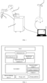
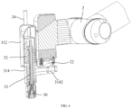
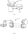
- the corresponding relation between the reference signs in Fig. 1-10 and the part names is as follows: 1 host, 2 mechanical arm, 22 end-of-arm tooling connector, 24 identification device, 26 recording device, 3 gun handle, 30 shock wave generator, 31 housing, 312 shell, 314 base, 3140 through hole, 3142 protrusion portion, 316 installation cavity, 32 power source control device, 33 silencing shock absorption pipe, 34 power source connecting path, 4 camera, 5 structural optical scanner, 6 coupling component, 7 therapy platform, 8 therapy aid, and 9 software planning device.
- the embodiments of the first aspect of the present invention provide a gun handle system which is used for a shock wave robot therapy system, wherein the shock wave robot therapy system comprises a host 1 and a gun handle system installed on the host 1, the gun handle system can move under the action of the host 1, and the gun handle system comprises a mechanical arm 2 and a gun handle 3, specifically:
- the gun handle system provided by the present invention is used for the shock wave robot therapy system, and the gun handle system comprises a mechanical arm 2 installed on the host 1 and a gun handle 3 installed at the tail end of the mechanical arm 2, wherein the mechanical arm 2 is used for driving the gun handle 3 to move under the control of the host 1, and the gun handle 3 and the mechanical arm 2 are detachably connected through an end-of-arm tooling connector 22 so that the gun handle 3 can be removed from the mechanical arm 2 and then other end-of-arm toolings can be installed on the mechanical arm 2.
- the identification device 24 is used for identifying end-of-arm toolings.
- the end-of-arm toolings which shall be installed can be controlled by the mechanical arm 2 and the host 1 through identification matching to realize the corresponding functions.
- the gun handle system in the present application can be installed on the host 1 through the mechanical arm 2 so that the gun handle system can realize intelligent mobile shock wave therapy under the action of the host 1.
- the gun handle 3 cannot be kept stable when held for a long time, which will affect the effective and stable transmission of shock wave energy to the treated part and thus cannot achieve an ideal therapeutic effect, and the continuous vibration of the shock wave gun handle 3 in the therapeutic process is likely to cause fatigue injury of the doctor's limbs so that the shock wave therapy effect is more ideal, the operation process is more intelligent, simple and stable, and the fatigue injury caused to the doctor's limbs by holding the gun handle 3 in hand can be avoided. Meanwhile, because the gun handle 3 can carry out mobile therapy under the drive of the mechanical arm 2, the structure can realize multipoint cyclic therapy, thereby realizing the mobile therapy of the shock wave gun handle 3 on the body surface while realizing the automatic shock wave therapy.
- a recording device 26 which can record the motion track of the mechanical arm 2 is arranged in the mechanical arm 2 or the host 1.
- an experienced doctor can manually control the gun handle 3 or the mechanical arm 2 for demonstration therapy first to enable the mechanical arm 2 or the host 1 to record the movement track of the mechanical arm through the recording device 26 in the process of demonstration therapy so that the mechanical arm can repeatedly execute the recorded motion track to realize automatic and mobile therapy.
- This way uses the function of automatically recording the path of the mechanical arm 2, and a camera and a graphical analysis device at the tail end of the mechanical arm can be omitted, so the load of the robot can be reduced.
- the gun handle system also comprises a visual acquisition device installed on the mechanical arm 2 or the gun handle 3, wherein the visual acquisition device is used for collecting image information about a patient's body surface.
- identification points and lines can be set on the patient's body surface first to indicate a preset therapeutic path, the information of the preset path marked on the patient's body surface is obtained through the visual acquisition device, a doctor can modify and confirm the image information of the preset path to plan a practical therapeutic path, and the robot can be controlled through instructions to perform reciprocating therapy.
- the mechanical arm 2 or the gun handle 3 is provided with a visual acquisition device for image acquisition, and after the visual acquisition device collects images, the therapeutic path of the gun handle 3 can be planned through analysis on the images so that the gun handle system can be controlled by the planned therapeutic path to carry out automatic and mobile therapy according to the planned path, which realizes the intelligent navigation of the mechanical arm 2 based on visual acquisition information, wherein the visual acquisition device can be the camera 4.
- a path editing module is arranged in the host 1, and the preliminary path can be subjected to reasonable editing or modification (including addition, deletion and adjustment) through the path editing module after being obtained through the recording device 26 so as to realize reasonable planning of the path.
- the mechanical arm 2 is a seven-degree-of-freedom flexible mechanical arm, wherein the seven-degree-of-freedom flexible mechanical arm 2 can be understood as an arm with flexibility closest to a human arm, the mechanical arm 2 can keep the base 314 and the end position unchanged, and the spatial attitude of the mechanical arm 2 can be changed.
- the gun handle system also comprises a coupling component 6 which is installed on the gun head, and the gun head is in contact with a patient's body surface through the coupling component 6 in the therapeutic process,wherein the coupling component 6 is used for realizing the interface coupling of the energy transmission process after being assembled with the gun head of the gun handle 3 of the shock wave robot to ensure the effective and stable transmission of shock wave energy.
- a solid coupling medium is embedded in the coupling component. In this way, it is not necessary to apply a couplant to the patient's body surface in advance, thus simplifying the operation.
- the gun head is not required to be provided with the coupling component 6, and at this time, the couplant can be applied to the patient's body surface in advance.
- the gun handle 3 also comprises: a housing 31 in which the shock wave generator 30 is installed, wherein the front end of the gun handle 3 extends out of the housing 31; and a silencing shock absorption pipe 33 which is installed in the housing 31 and sheathed on the shock wave generator 30.
- the gun handle 3 comprises a shell 312, a shock wave generator 30 and a silencing shock absorption pipe 33
- the housing 31 is composed of the shell 312 and a base 314, and the silencing shock absorption pipe 33 is used for reducing noise and vibration so as to reduce noise and vibration of the shock wave generator 30 in the process of generating shock wave so that the gun handle is quieter in use.
- the housing 31 comprises the base 314 and the shell 312 installed on the base 314, an installation cavity 316 is formed between the shell 312 and the base 314, the base 314 is provided with a through hole 3140 communicating with the installation cavity 316, and the base 314 can be detachably connected with the end-of-arm tooling connector 22; and the gun handle 3 also comprises: a power source control device 32 which is installed in the housing 31 and provided with an accommodating cavity, wherein the accommodating cavity is provided with an opening at one end close to the base 314, one end of the shock wave generator 30 is installed in the accommodating cavity, the other end of the shock wave generator 30 penetrates through the opening of the accommodating cavity and extends out of the base 314 through the through hole 3140, and the power source control device 32 is connected with the power source for providing the power source for the shock wave generator 30 after control treatment wherein the silencing shock absorption pipe 33 is located in a space surrounded by the power source control device 32 and the base 314, and sheathed on the
- the housing 31 is composed of the shell 312 and the base 314, and the power source control device 32 is used for controlling the operation of the shock wave generator 30 to ensure that the shock wave generator 30 can generate shock wave with required parameters.
- the base 314 and the shell 312 are connected through screws.
- the gun handle 3 also comprises a power source connecting path 34 installed on the shell 312, wherein the power source connecting path 34 is used for communicating the shock wave generator 30 with the shock wave power source.
- the power source control device 32 is installed in the housing and used for controlling the shock wave power source to be on and off.
- a power source required by the shock wave generator 30 can be hydra electronic, piezoelectric, electromagnetic, pneumatic, etc.
- the base 314 is provided with a protrusion portion 3142, the protrusion portion 3142 is arranged by extending out of the side portion of the shell 312 and used for being connected with the end-of-arm tooling connector 22, the end-of-arm tooling connector 22 is fixedly connected with the tail end of the mechanical arm 2, and when the mechanical arm 2 is connected with the end-of-arm tooling connector 22, part of the structure of the tail end of the mechanical arm 2 is abutted against part of the housing 31 located above the protrusion portion 3142.
- This arrangement can make the mechanical arm 2 and the gun handle 3 match more reliably.
- the embodiment of the second aspect of the present invention provides a shock wave robot therapy system, comprising: a host 1; and a gun handle system provided by any of the embodiments of the first aspect, wherein the gun handle system is installed to the host 1 through the mechanical arm 2 and can move under the control of the host 1.
- the shock wave robot therapy system provided by the embodiment of the second aspect of the present invention comprises the gun handle system provided by any of the embodiments of the first aspect and thus comprises the beneficial effects of the gun handle system provided by any of the embodiments of the first aspect, which will not be repeated herein.
- the shock wave robot therapy system also comprises a therapy platform 7 for a patient to sit or lie down and therapy aids 8 for ensuring a patient's therapy posture.
- the therapy platform 7 is a therapeutic bed or a therapeutic chair
- the therapy aids 8 comprise one or more of a positioning tool for positioning a patient, a fixture for partially fixing a patient and a positioning and supporting device for positioning and/or supporting the shock wave robot and the gun handle 3, wherein the therapeutic bed (or chair) of the shock wave robot and the other therapy aids 8 of the shock wave robot are appliances selected or customized for meeting the requirements of shock wave robot therapy to maintain the patient's therapy posture, which not only meet the functional requirements but also let a patient feel very comfortable in the therapeutic process.
- the host 1 and the structural optical scanner 5 also can be externally connected with a software planning device 9 to facilitate program editing and management on the host 1 and the structural optical scanner 5.
- shock wave robot therapy system also comprises other end-of-arm toolings (not shown in the figures).
- the application process of the shock wave robot therapy system provided by the present invention in clinical practice can be divided into two modes of application: one is the demonstration mode of automatically recoding a track based on the mechanical arm, and the other is the autonomous navigation mode of generating a path based on image acquisition and analysis.
- the operation process of the clinical flow in the autonomous navigation mode is as follows:
- the axis of the gun head of the gun handle of the shock wave robot is required to be always perpendicular to the body surface of the affected part, and meanwhile, the end surface of the gun head of the gun handle is required to remain in contact with the body surface and keep a constant force.
- connection means such as “connecting”, “installation”, “fixation” and the like shall be understood in broad sense, and for example, may refer to fixed connection or detachable connection or integral connection, and may refer to direct connection or indirect connection through an intermediate medium.
- connection may refer to fixed connection or detachable connection or integral connection, and may refer to direct connection or indirect connection through an intermediate medium.
- connection may refer to fixed connection or detachable connection or integral connection, and may refer to direct connection or indirect connection through an intermediate medium.
Landscapes
- Health & Medical Sciences (AREA)
- Epidemiology (AREA)
- Pain & Pain Management (AREA)
- Physical Education & Sports Medicine (AREA)
- Rehabilitation Therapy (AREA)
- Life Sciences & Earth Sciences (AREA)
- Animal Behavior & Ethology (AREA)
- General Health & Medical Sciences (AREA)
- Public Health (AREA)
- Veterinary Medicine (AREA)
- Manipulator (AREA)
Claims (9)
- Pistolengriffsystem, das für ein Stoßwellenroboter-Therapiesystem verwendet wird, das aufweist:einen mechanischen Arm (2), der an einem Träger (1) des Stoßwellenroboter-Therapiesystems installiert ist, wobei das hintere Ende des mechanischen Arms mit einem Armende-Werkzeuganschluss (22) versehen ist, der sich an verschiedene Armende-Werkzeuge anpassen kann;einen Pistolengriff (3), der abnehmbar an dem Armende-Werkzeuganschluss installiert ist und sich unter dem Antrieb des mechanischen Arms bewegen kann, wobei ein Stoßwellengenerator (30) in dem Pistolengriff angeordnet ist und das vordere Ende des Pistolengriffs mit einem Pistolenkopf versehen ist, der für den Kontakt mit einer Körperoberfläche eines Patienten verwendet wird,dadurch gekennzeichnet, dasseine Aufzeichnungsvorrichtung (26) in dem mechanischen Arm oder dem Träger angeordnet ist und dazu eingerichtet ist, eine Bewegungsspur des mechanischen Arms aufzuzeichnen, wobei der mechanische Arm dazu eingerichtet ist, die aufgezeichnete Bewegungsspur wiederholt auszuführen.
- Pistolengriffsystem nach Anspruch 1, wobei der Pistolengriff auch aufweist:ein Gehäuse (31), in dem der Stoßwellengenerator installiert ist, wobei sich das vordere Ende des Pistolengriffs aus dem Gehäuse heraus erstreckt; und das Gehäuse einen Sockel (314) und eine auf dem Sockel installierte Schale (312) aufweist, wobei ein Installationshohlraum (316) zwischen der Schale und dem Sockel ausgebildet ist, der Sockel mit einem Durchgangsloch (3140) versehen ist, das mit dem Installationshohlraum in Verbindung steht, und der Sockel abnehmbar mit dem Armende-Werkzeuganschluss verbunden werden kann;ein schalldämpfendes Stoßdämpfungsrohr (33), das in dem Gehäuse installiert ist.
- Pistolengriffsystem nach Anspruch 2, wobei der Pistolengriff auch aufweist:eine Vorrichtung zur Steuerung der Energiequelle (32), die in dem Gehäuse installiert und mit einem Aufnahmehohlraum versehen ist, wobei der Aufnahmehohlraum an einem Ende nahe dem Sockel mit einer Öffnung versehen ist, ein Ende des Stoßwellengenerators in dem Aufnahmehohlraum installiert ist und das andere Ende des Stoßwellengenerators durch die Öffnung des Aufnahmehohlraums hindurchdringt und sich durch das Durchgangsloch aus dem Sockel heraus erstreckt; und die Vorrichtung zur Steuerung der Energiequelle zur Steuerung des Ein- und Ausschaltens einer Stoßwellenenergiequelle verwendet wird;einen Stromquellenverbindungspfad (34), der zur Verbindung des Stoßwellengenerators mit der Stoßwellenenergiequelle dient,und wobei das schalldämpfende Stoßdämpfungsrohr in einem Raum angeordnet ist, der von der Vorrichtung zur Steuerung der Energiequelle und dem Sockel umgeben ist, und von dem Stoßwellengenerator ummantelt ist.
- Pistolengriffsystem nach Anspruch 2, wobei
der Sockel mit einem Vorsprungsabschnitt (3142) versehen ist, der Vorsprungsabschnitt so angeordnet ist, dass er sich aus dem Seitenabschnitt der Schale heraus erstreckt und dazu verwendet wird, mit dem Armende-Werkzeuganschluss verbunden zu werden, das hintere Ende des mechanischen Arms mit dem Armende-Werkzeuganschluss von oberhalb des Armende-Werkzeuganschlusses verbunden werden kann, und wenn der mechanische Arm mit dem Armende-Werkzeuganschluss verbunden ist, ein Teil der Struktur des mechanischen Arms gegen einen Teil des Gehäuses, der sich oberhalb des Vorsprungsabschnitts befindet, anstößt. - Pistolengriffsystem nach einem der Ansprüche 1-4, wobei
das Pistolengriffsystem auch eine Identifikationsvorrichtung (24) aufweist, die mit dem Träger verbunden ist, wobei die Identifikationsvorrichtung ein mit dem Armende-Werkzeuganschluss verbundenes Armende-Werkzeug identifizieren kann und der Pistolengriff eines der Armende-Werkzeuge ist. - Pistolengriffsystem nach einem der Ansprüche 1-4, wobei
das Pistolengriffsystem auch eine Vorrichtung zur visuellen Erfassung aufweist, die am mechanischen Arm oder am Pistolengriff installiert ist, wobei die Vorrichtung zur visuellen Erfassung zur Erfassung von Bildinformationen über die Körperoberfläche eines Patienten verwendet wird. - Pistolengriffsystem nach einem der Ansprüche 1-4, wobei
der mechanische Arm ist ein flexibler mechanischer Arm mit sieben Freiheitsgraden. - Pistolengriffsystem nach einem der Ansprüche 1-4, wobei
das Pistolengriffsystem auch einen koppelnden Bestandteil (6) aufweist, der auf dem Pistolenkopf installiert ist, und der Pistolenkopf durch den koppelnden Bestandteil während des therapeutischen Prozesses in Kontakt mit der Körperoberfläche eines Patienten ist. - Stoßwellenroboter-Therapiesystem, das aufweist:einen Träger (1), unddas Pistolengriffsystem nach einem der Ansprüche 1 bis 8, wobei das Pistolengriffsystem über den mechanischen Arm an dem Träger installiert ist und sich unter der Kontrolle des Trägers bewegen kann.
Applications Claiming Priority (1)
| Application Number | Priority Date | Filing Date | Title |
|---|---|---|---|
| CN202010573174.2A CN111588613B (zh) | 2020-06-22 | 2020-06-22 | 一种枪柄系统及冲击波机器人治疗系统 |
Publications (3)
| Publication Number | Publication Date |
|---|---|
| EP3928757A1 EP3928757A1 (de) | 2021-12-29 |
| EP3928757C0 EP3928757C0 (de) | 2024-07-31 |
| EP3928757B1 true EP3928757B1 (de) | 2024-07-31 |
Family
ID=72182792
Family Applications (1)
| Application Number | Title | Priority Date | Filing Date |
|---|---|---|---|
| EP21180213.7A Active EP3928757B1 (de) | 2020-06-22 | 2021-06-18 | Pistolengriffsystem und stosswellenrobotertherapiesystem |
Country Status (2)
| Country | Link |
|---|---|
| EP (1) | EP3928757B1 (de) |
| CN (1) | CN111588613B (de) |
Families Citing this family (8)
| Publication number | Priority date | Publication date | Assignee | Title |
|---|---|---|---|---|
| CN112656378A (zh) * | 2021-01-11 | 2021-04-16 | 北京积水潭医院 | 一种医用红外热像检测机器人及治疗方法 |
| CN113558718B (zh) * | 2021-07-31 | 2023-11-03 | 任晓东 | 体外冲击波治疗装置 |
| CN114344118A (zh) * | 2022-01-05 | 2022-04-15 | 苏州好博医疗器械股份有限公司 | 一种冲击波手柄 |
| CN114617638A (zh) * | 2022-03-23 | 2022-06-14 | 杭州键嘉机器人有限公司 | 一种新型骨科手术机器人结构及使用方法 |
| CN116810845A (zh) * | 2023-06-14 | 2023-09-29 | 中山大学 | 夹持装置、机械臂及工件的识别方法 |
| CN117045483B (zh) * | 2023-08-14 | 2025-12-12 | 北京航空航天大学 | 一种骨科冲击波治疗靶向操作机器人工具 |
| CN116747125B (zh) * | 2023-08-15 | 2025-09-30 | 郑州仁惠医疗科技股份有限公司 | 一种用于疼痛康复的体外冲击波磁振治疗仪 |
| CN116942517B (zh) * | 2023-08-17 | 2026-01-13 | 深圳市古瑞德医疗科技有限责任公司 | 一种自动取放艾条的艾灸机器人 |
Family Cites Families (15)
| Publication number | Priority date | Publication date | Assignee | Title |
|---|---|---|---|---|
| DE102006059443A1 (de) * | 2006-12-15 | 2008-06-19 | Siemens Ag | Lithotripsieeinrichtung |
| CN101884585A (zh) * | 2010-07-30 | 2010-11-17 | 山东建筑大学 | 一种中医推拿机器人控制系统 |
| US10493293B2 (en) * | 2015-07-01 | 2019-12-03 | Btl Medical Technologies S.R.O. | Aesthetic method of biological structure treatment by magnetic field |
| CN107929024A (zh) * | 2017-12-08 | 2018-04-20 | 韩元元 | 一种姿势可调型医疗手臂按摩机器人 |
| CN107972049B (zh) * | 2018-01-18 | 2023-07-28 | 开封市平安电器有限公司 | 用于按摩、锤击的机械手 |
| CN108187250A (zh) * | 2018-02-07 | 2018-06-22 | 苏州元禾医疗器械有限公司 | 一种自动皮肤治疗装置 |
| CN108785045A (zh) * | 2018-03-20 | 2018-11-13 | 谢安迪 | 一种新型的骨科体外冲击波治疗仪 |
| CN208989547U (zh) * | 2018-04-20 | 2019-06-18 | 奥佳华智能健康科技集团股份有限公司 | 一种按摩床结构 |
| CN111096772A (zh) * | 2018-10-25 | 2020-05-05 | 比亚迪股份有限公司 | 冲击波治疗仪 |
| CN111166641A (zh) * | 2018-11-12 | 2020-05-19 | 旭海顾普乐(天津)医疗器械科技有限公司 | 一种体外冲击波治疗仪 |
| CN110037910A (zh) * | 2019-03-22 | 2019-07-23 | 同济大学 | 一种基于realsense的多功能自动理疗机 |
| CN110772415A (zh) * | 2019-11-26 | 2020-02-11 | 徐州康良电子科技有限公司 | 用于冲击波治疗机的冲击波源移动机械装置 |
| CN110782982B (zh) * | 2019-12-05 | 2022-05-31 | 中科尚易健康科技(北京)有限公司 | 一种基于二维码的人体经络路径方法 |
| CN111135070A (zh) * | 2020-01-10 | 2020-05-12 | 浙江工业大学 | 一种基于机器视觉的智能艾灸治疗机及其工作方法 |
| CN212940510U (zh) * | 2020-06-22 | 2021-04-13 | 北京积水潭医院 | 一种枪柄系统及冲击波机器人治疗系统 |
-
2020
- 2020-06-22 CN CN202010573174.2A patent/CN111588613B/zh active Active
-
2021
- 2021-06-18 EP EP21180213.7A patent/EP3928757B1/de active Active
Also Published As
| Publication number | Publication date |
|---|---|
| EP3928757C0 (de) | 2024-07-31 |
| CN111588613B (zh) | 2025-05-06 |
| EP3928757A1 (de) | 2021-12-29 |
| CN111588613A (zh) | 2020-08-28 |
Similar Documents
| Publication | Publication Date | Title |
|---|---|---|
| EP3928757A1 (de) | Pistolengriffsystem und stosswellenrobotertherapiesystem | |
| CN111631763B (zh) | 一种冲击波机器人治疗系统 | |
| CN112770691B (zh) | 用于机器人手术的带反馈的基准标记器 | |
| CN111671635A (zh) | 一种基于结构光定位的冲击波机器人治疗系统 | |
| CN206026424U (zh) | 一种智能骨科手术系统 | |
| RU2547180C2 (ru) | Система и способ для косметической обработки и визуализации | |
| EP2412406B1 (de) | Medizinischer Roboter und medinzinischer Arbeitsplatz | |
| CN101670152B (zh) | 光动力治疗系统 | |
| JP2018518254A (ja) | 生体構造の計画された自律加工を実証するシステム及び方法 | |
| BRPI0417907A (pt) | cabeçote para ultra-som, aplicador de energia, meio para manobrar o mesmo, e, método para distribuir energia de ultra-som a uma superfìcie do corpo | |
| CN101361678A (zh) | 用于机器人手术的基于工具存储器的软件更新 | |
| JP6234267B2 (ja) | 手術用マニピュレータ操作装置および手術用マニピュレータシステム | |
| WO2004002319A3 (en) | Method and apparatus for positioning a surgical instrument | |
| CN111135070A (zh) | 一种基于机器视觉的智能艾灸治疗机及其工作方法 | |
| CN114305679B (zh) | 一种辅助运动装置、驱动系统及控制方法 | |
| US12377254B2 (en) | Tattoo device | |
| US20220133342A1 (en) | Device for conditioning ex vivo pericardial tissue | |
| CN1743026A (zh) | 上百阵元复合材料球面相控阵高强度聚焦超声治疗系统 | |
| CN212940510U (zh) | 一种枪柄系统及冲击波机器人治疗系统 | |
| JP6866417B2 (ja) | アダプタおよびアダプタの装着方法 | |
| US6406443B1 (en) | Self-contained ultrasound applicator | |
| KR20130015441A (ko) | 수술용 로봇 시스템 | |
| CN114225241A (zh) | 超声波医疗用盒、超声波医疗装置及防齿隙装置 | |
| KR101676012B1 (ko) | 피부 미용 시술 장치 | |
| CN118593070A (zh) | 一种电动弯转的医用取物手术器械 |
Legal Events
| Date | Code | Title | Description |
|---|---|---|---|
| PUAI | Public reference made under article 153(3) epc to a published international application that has entered the european phase |
Free format text: ORIGINAL CODE: 0009012 |
|
| STAA | Information on the status of an ep patent application or granted ep patent |
Free format text: STATUS: REQUEST FOR EXAMINATION WAS MADE |
|
| 17P | Request for examination filed |
Effective date: 20210618 |
|
| AK | Designated contracting states |
Kind code of ref document: A1 Designated state(s): AL AT BE BG CH CY CZ DE DK EE ES FI FR GB GR HR HU IE IS IT LI LT LU LV MC MK MT NL NO PL PT RO RS SE SI SK SM TR |
|
| B565 | Issuance of search results under rule 164(2) epc |
Effective date: 20211124 |
|
| GRAP | Despatch of communication of intention to grant a patent |
Free format text: ORIGINAL CODE: EPIDOSNIGR1 |
|
| STAA | Information on the status of an ep patent application or granted ep patent |
Free format text: STATUS: GRANT OF PATENT IS INTENDED |
|
| RIC1 | Information provided on ipc code assigned before grant |
Ipc: A61H 23/00 20060101ALN20240125BHEP Ipc: A61H 1/00 20060101AFI20240125BHEP |
|
| INTG | Intention to grant announced |
Effective date: 20240208 |
|
| RIN1 | Information on inventor provided before grant (corrected) |
Inventor name: GUO, ANYI Inventor name: LIU, YAJUN |
|
| GRAS | Grant fee paid |
Free format text: ORIGINAL CODE: EPIDOSNIGR3 |
|
| GRAA | (expected) grant |
Free format text: ORIGINAL CODE: 0009210 |
|
| STAA | Information on the status of an ep patent application or granted ep patent |
Free format text: STATUS: THE PATENT HAS BEEN GRANTED |
|
| AK | Designated contracting states |
Kind code of ref document: B1 Designated state(s): AL AT BE BG CH CY CZ DE DK EE ES FI FR GB GR HR HU IE IS IT LI LT LU LV MC MK MT NL NO PL PT RO RS SE SI SK SM TR |
|
| REG | Reference to a national code |
Ref country code: CH Ref legal event code: EP Ref country code: GB Ref legal event code: FG4D |
|
| REG | Reference to a national code |
Ref country code: DE Ref legal event code: R096 Ref document number: 602021016359 Country of ref document: DE |
|
| REG | Reference to a national code |
Ref country code: IE Ref legal event code: FG4D |
|
| U01 | Request for unitary effect filed |
Effective date: 20240801 |
|
| U07 | Unitary effect registered |
Designated state(s): AT BE BG DE DK EE FI FR IT LT LU LV MT NL PT SE SI Effective date: 20240820 |
|
| U1N | Appointed representative for the unitary patent procedure changed after the registration of the unitary effect |
Representative=s name: VALET PATENT SERVICES LIMITED; DE |
|
| PG25 | Lapsed in a contracting state [announced via postgrant information from national office to epo] |
Ref country code: NO Free format text: LAPSE BECAUSE OF FAILURE TO SUBMIT A TRANSLATION OF THE DESCRIPTION OR TO PAY THE FEE WITHIN THE PRESCRIBED TIME-LIMIT Effective date: 20241031 |
|
| PG25 | Lapsed in a contracting state [announced via postgrant information from national office to epo] |
Ref country code: PL Free format text: LAPSE BECAUSE OF FAILURE TO SUBMIT A TRANSLATION OF THE DESCRIPTION OR TO PAY THE FEE WITHIN THE PRESCRIBED TIME-LIMIT Effective date: 20240731 Ref country code: GR Free format text: LAPSE BECAUSE OF FAILURE TO SUBMIT A TRANSLATION OF THE DESCRIPTION OR TO PAY THE FEE WITHIN THE PRESCRIBED TIME-LIMIT Effective date: 20241101 |
|
| PG25 | Lapsed in a contracting state [announced via postgrant information from national office to epo] |
Ref country code: IS Free format text: LAPSE BECAUSE OF FAILURE TO SUBMIT A TRANSLATION OF THE DESCRIPTION OR TO PAY THE FEE WITHIN THE PRESCRIBED TIME-LIMIT Effective date: 20241130 |
|
| PG25 | Lapsed in a contracting state [announced via postgrant information from national office to epo] |
Ref country code: HR Free format text: LAPSE BECAUSE OF FAILURE TO SUBMIT A TRANSLATION OF THE DESCRIPTION OR TO PAY THE FEE WITHIN THE PRESCRIBED TIME-LIMIT Effective date: 20240731 |
|
| PG25 | Lapsed in a contracting state [announced via postgrant information from national office to epo] |
Ref country code: RS Free format text: LAPSE BECAUSE OF FAILURE TO SUBMIT A TRANSLATION OF THE DESCRIPTION OR TO PAY THE FEE WITHIN THE PRESCRIBED TIME-LIMIT Effective date: 20241031 Ref country code: ES Free format text: LAPSE BECAUSE OF FAILURE TO SUBMIT A TRANSLATION OF THE DESCRIPTION OR TO PAY THE FEE WITHIN THE PRESCRIBED TIME-LIMIT Effective date: 20240731 |
|
| PG25 | Lapsed in a contracting state [announced via postgrant information from national office to epo] |
Ref country code: RS Free format text: LAPSE BECAUSE OF FAILURE TO SUBMIT A TRANSLATION OF THE DESCRIPTION OR TO PAY THE FEE WITHIN THE PRESCRIBED TIME-LIMIT Effective date: 20241031 Ref country code: PL Free format text: LAPSE BECAUSE OF FAILURE TO SUBMIT A TRANSLATION OF THE DESCRIPTION OR TO PAY THE FEE WITHIN THE PRESCRIBED TIME-LIMIT Effective date: 20240731 Ref country code: NO Free format text: LAPSE BECAUSE OF FAILURE TO SUBMIT A TRANSLATION OF THE DESCRIPTION OR TO PAY THE FEE WITHIN THE PRESCRIBED TIME-LIMIT Effective date: 20241031 Ref country code: IS Free format text: LAPSE BECAUSE OF FAILURE TO SUBMIT A TRANSLATION OF THE DESCRIPTION OR TO PAY THE FEE WITHIN THE PRESCRIBED TIME-LIMIT Effective date: 20241130 Ref country code: HR Free format text: LAPSE BECAUSE OF FAILURE TO SUBMIT A TRANSLATION OF THE DESCRIPTION OR TO PAY THE FEE WITHIN THE PRESCRIBED TIME-LIMIT Effective date: 20240731 Ref country code: GR Free format text: LAPSE BECAUSE OF FAILURE TO SUBMIT A TRANSLATION OF THE DESCRIPTION OR TO PAY THE FEE WITHIN THE PRESCRIBED TIME-LIMIT Effective date: 20241101 Ref country code: ES Free format text: LAPSE BECAUSE OF FAILURE TO SUBMIT A TRANSLATION OF THE DESCRIPTION OR TO PAY THE FEE WITHIN THE PRESCRIBED TIME-LIMIT Effective date: 20240731 |
|
| PG25 | Lapsed in a contracting state [announced via postgrant information from national office to epo] |
Ref country code: SM Free format text: LAPSE BECAUSE OF FAILURE TO SUBMIT A TRANSLATION OF THE DESCRIPTION OR TO PAY THE FEE WITHIN THE PRESCRIBED TIME-LIMIT Effective date: 20240731 |
|
| PG25 | Lapsed in a contracting state [announced via postgrant information from national office to epo] |
Ref country code: CZ Free format text: LAPSE BECAUSE OF FAILURE TO SUBMIT A TRANSLATION OF THE DESCRIPTION OR TO PAY THE FEE WITHIN THE PRESCRIBED TIME-LIMIT Effective date: 20240731 |
|
| PG25 | Lapsed in a contracting state [announced via postgrant information from national office to epo] |
Ref country code: SK Free format text: LAPSE BECAUSE OF FAILURE TO SUBMIT A TRANSLATION OF THE DESCRIPTION OR TO PAY THE FEE WITHIN THE PRESCRIBED TIME-LIMIT Effective date: 20240731 |
|
| PLBE | No opposition filed within time limit |
Free format text: ORIGINAL CODE: 0009261 |
|
| STAA | Information on the status of an ep patent application or granted ep patent |
Free format text: STATUS: NO OPPOSITION FILED WITHIN TIME LIMIT |
|
| U20 | Renewal fee for the european patent with unitary effect paid |
Year of fee payment: 5 Effective date: 20250520 |
|
| 26N | No opposition filed |
Effective date: 20250501 |
|
| REG | Reference to a national code |
Ref country code: CH Ref legal event code: H13 Free format text: ST27 STATUS EVENT CODE: U-0-0-H10-H13 (AS PROVIDED BY THE NATIONAL OFFICE) Effective date: 20260127 |
|
| PG25 | Lapsed in a contracting state [announced via postgrant information from national office to epo] |
Ref country code: MC Free format text: LAPSE BECAUSE OF FAILURE TO SUBMIT A TRANSLATION OF THE DESCRIPTION OR TO PAY THE FEE WITHIN THE PRESCRIBED TIME-LIMIT Effective date: 20240731 |
|
| GBPC | Gb: european patent ceased through non-payment of renewal fee |
Effective date: 20250618 |
|
| PG25 | Lapsed in a contracting state [announced via postgrant information from national office to epo] |
Ref country code: GB Free format text: LAPSE BECAUSE OF NON-PAYMENT OF DUE FEES Effective date: 20250618 |
|
| PG25 | Lapsed in a contracting state [announced via postgrant information from national office to epo] |
Ref country code: IE Free format text: LAPSE BECAUSE OF NON-PAYMENT OF DUE FEES Effective date: 20250618 |
|
| PG25 | Lapsed in a contracting state [announced via postgrant information from national office to epo] |
Ref country code: RO Free format text: LAPSE BECAUSE OF FAILURE TO SUBMIT A TRANSLATION OF THE DESCRIPTION OR TO PAY THE FEE WITHIN THE PRESCRIBED TIME-LIMIT Effective date: 20240731 |
|
| PG25 | Lapsed in a contracting state [announced via postgrant information from national office to epo] |
Ref country code: CH Free format text: LAPSE BECAUSE OF NON-PAYMENT OF DUE FEES Effective date: 20250630 |
|
| U20 | Renewal fee for the european patent with unitary effect paid |
Year of fee payment: 6 Effective date: 20260409 |
|
| PG25 | Lapsed in a contracting state [announced via postgrant information from national office to epo] |
Ref country code: CY Free format text: LAPSE BECAUSE OF FAILURE TO SUBMIT A TRANSLATION OF THE DESCRIPTION OR TO PAY THE FEE WITHIN THE PRESCRIBED TIME-LIMIT Effective date: 20240731 |