EP3928688B1 - Transkutane analytsensoren, applikatoren dafür und nadelnabe mit verdrehsicherung - Google Patents
Transkutane analytsensoren, applikatoren dafür und nadelnabe mit verdrehsicherung Download PDFInfo
- Publication number
- EP3928688B1 EP3928688B1 EP21179820.2A EP21179820A EP3928688B1 EP 3928688 B1 EP3928688 B1 EP 3928688B1 EP 21179820 A EP21179820 A EP 21179820A EP 3928688 B1 EP3928688 B1 EP 3928688B1
- Authority
- EP
- European Patent Office
- Prior art keywords
- applicator
- assembly
- spring
- needle carrier
- skin sensor
- Prior art date
- Legal status (The legal status is an assumption and is not a legal conclusion. Google has not performed a legal analysis and makes no representation as to the accuracy of the status listed.)
- Active
Links
- 239000012491 analyte Substances 0.000 title description 96
- 238000003780 insertion Methods 0.000 claims description 659
- 230000037431 insertion Effects 0.000 claims description 659
- 230000003100 immobilizing effect Effects 0.000 claims description 8
- 230000000295 complement effect Effects 0.000 claims description 6
- 230000014759 maintenance of location Effects 0.000 description 484
- 230000004913 activation Effects 0.000 description 302
- 230000007246 mechanism Effects 0.000 description 112
- 239000000853 adhesive Substances 0.000 description 72
- 230000001070 adhesive effect Effects 0.000 description 72
- 239000000463 material Substances 0.000 description 56
- 238000000034 method Methods 0.000 description 54
- 230000033001 locomotion Effects 0.000 description 36
- 230000008878 coupling Effects 0.000 description 33
- 238000010168 coupling process Methods 0.000 description 33
- 238000005859 coupling reaction Methods 0.000 description 33
- 239000010410 layer Substances 0.000 description 31
- 238000004804 winding Methods 0.000 description 28
- 230000006870 function Effects 0.000 description 27
- 230000003213 activating effect Effects 0.000 description 25
- 230000004888 barrier function Effects 0.000 description 24
- 229920000642 polymer Polymers 0.000 description 24
- WQZGKKKJIJFFOK-GASJEMHNSA-N Glucose Natural products OC[C@H]1OC(O)[C@H](O)[C@@H](O)[C@@H]1O WQZGKKKJIJFFOK-GASJEMHNSA-N 0.000 description 21
- -1 PreState Chemical compound 0.000 description 21
- 238000004891 communication Methods 0.000 description 21
- 239000008103 glucose Substances 0.000 description 21
- 230000006835 compression Effects 0.000 description 18
- 238000007906 compression Methods 0.000 description 18
- 229920001971 elastomer Polymers 0.000 description 18
- NOESYZHRGYRDHS-UHFFFAOYSA-N insulin Chemical compound N1C(=O)C(NC(=O)C(CCC(N)=O)NC(=O)C(CCC(O)=O)NC(=O)C(C(C)C)NC(=O)C(NC(=O)CN)C(C)CC)CSSCC(C(NC(CO)C(=O)NC(CC(C)C)C(=O)NC(CC=2C=CC(O)=CC=2)C(=O)NC(CCC(N)=O)C(=O)NC(CC(C)C)C(=O)NC(CCC(O)=O)C(=O)NC(CC(N)=O)C(=O)NC(CC=2C=CC(O)=CC=2)C(=O)NC(CSSCC(NC(=O)C(C(C)C)NC(=O)C(CC(C)C)NC(=O)C(CC=2C=CC(O)=CC=2)NC(=O)C(CC(C)C)NC(=O)C(C)NC(=O)C(CCC(O)=O)NC(=O)C(C(C)C)NC(=O)C(CC(C)C)NC(=O)C(CC=2NC=NC=2)NC(=O)C(CO)NC(=O)CNC2=O)C(=O)NCC(=O)NC(CCC(O)=O)C(=O)NC(CCCNC(N)=N)C(=O)NCC(=O)NC(CC=3C=CC=CC=3)C(=O)NC(CC=3C=CC=CC=3)C(=O)NC(CC=3C=CC(O)=CC=3)C(=O)NC(C(C)O)C(=O)N3C(CCC3)C(=O)NC(CCCCN)C(=O)NC(C)C(O)=O)C(=O)NC(CC(N)=O)C(O)=O)=O)NC(=O)C(C(C)CC)NC(=O)C(CO)NC(=O)C(C(C)O)NC(=O)C1CSSCC2NC(=O)C(CC(C)C)NC(=O)C(NC(=O)C(CCC(N)=O)NC(=O)C(CC(N)=O)NC(=O)C(NC(=O)C(N)CC=1C=CC=CC=1)C(C)C)CC1=CN=CN1 NOESYZHRGYRDHS-UHFFFAOYSA-N 0.000 description 16
- 230000008569 process Effects 0.000 description 15
- 230000000670 limiting effect Effects 0.000 description 14
- 230000001954 sterilising effect Effects 0.000 description 14
- 230000002441 reversible effect Effects 0.000 description 13
- 238000007789 sealing Methods 0.000 description 13
- 230000006378 damage Effects 0.000 description 12
- 238000004806 packaging method and process Methods 0.000 description 12
- 206010052428 Wound Diseases 0.000 description 11
- 230000003014 reinforcing effect Effects 0.000 description 11
- 208000027418 Wounds and injury Diseases 0.000 description 10
- 230000000717 retained effect Effects 0.000 description 10
- 238000004659 sterilization and disinfection Methods 0.000 description 10
- 230000001960 triggered effect Effects 0.000 description 10
- 210000004369 blood Anatomy 0.000 description 9
- 239000008280 blood Substances 0.000 description 9
- 239000003814 drug Substances 0.000 description 9
- 102000004877 Insulin Human genes 0.000 description 8
- 108090001061 Insulin Proteins 0.000 description 8
- 230000000712 assembly Effects 0.000 description 8
- 238000000429 assembly Methods 0.000 description 8
- 239000000806 elastomer Substances 0.000 description 8
- 229940125396 insulin Drugs 0.000 description 8
- 238000005259 measurement Methods 0.000 description 8
- 230000002829 reductive effect Effects 0.000 description 8
- 230000004044 response Effects 0.000 description 8
- 230000008901 benefit Effects 0.000 description 7
- 229920003023 plastic Polymers 0.000 description 7
- 239000004033 plastic Substances 0.000 description 7
- 238000003825 pressing Methods 0.000 description 7
- 238000012545 processing Methods 0.000 description 7
- 230000008093 supporting effect Effects 0.000 description 7
- 238000013519 translation Methods 0.000 description 7
- 230000009471 action Effects 0.000 description 6
- 239000012777 electrically insulating material Substances 0.000 description 6
- 239000006260 foam Substances 0.000 description 6
- 238000004519 manufacturing process Methods 0.000 description 6
- 238000012546 transfer Methods 0.000 description 6
- 239000004743 Polypropylene Substances 0.000 description 5
- 229910021607 Silver chloride Inorganic materials 0.000 description 5
- 229920000122 acrylonitrile butadiene styrene Polymers 0.000 description 5
- 239000004676 acrylonitrile butadiene styrene Substances 0.000 description 5
- ZPUCINDJVBIVPJ-LJISPDSOSA-N cocaine Chemical compound O([C@H]1C[C@@H]2CC[C@@H](N2C)[C@H]1C(=O)OC)C(=O)C1=CC=CC=C1 ZPUCINDJVBIVPJ-LJISPDSOSA-N 0.000 description 5
- 238000013461 design Methods 0.000 description 5
- 206010012601 diabetes mellitus Diseases 0.000 description 5
- 230000000977 initiatory effect Effects 0.000 description 5
- 230000004048 modification Effects 0.000 description 5
- 238000012986 modification Methods 0.000 description 5
- 239000004417 polycarbonate Substances 0.000 description 5
- 229920000139 polyethylene terephthalate Polymers 0.000 description 5
- 239000005020 polyethylene terephthalate Substances 0.000 description 5
- 229920001155 polypropylene Polymers 0.000 description 5
- 229920001296 polysiloxane Polymers 0.000 description 5
- HKZLPVFGJNLROG-UHFFFAOYSA-M silver monochloride Chemical compound [Cl-].[Ag+] HKZLPVFGJNLROG-UHFFFAOYSA-M 0.000 description 5
- 239000000126 substance Substances 0.000 description 5
- 239000000758 substrate Substances 0.000 description 5
- 210000001519 tissue Anatomy 0.000 description 5
- CFFZDZCDUFSOFZ-UHFFFAOYSA-N 3,4-Dihydroxy-phenylacetic acid Chemical compound OC(=O)CC1=CC=C(O)C(O)=C1 CFFZDZCDUFSOFZ-UHFFFAOYSA-N 0.000 description 4
- 229920000089 Cyclic olefin copolymer Polymers 0.000 description 4
- 239000004677 Nylon Substances 0.000 description 4
- 239000004698 Polyethylene Substances 0.000 description 4
- 239000004820 Pressure-sensitive adhesive Substances 0.000 description 4
- NIXOWILDQLNWCW-UHFFFAOYSA-N acrylic acid group Chemical group C(C=C)(=O)O NIXOWILDQLNWCW-UHFFFAOYSA-N 0.000 description 4
- 238000005452 bending Methods 0.000 description 4
- 238000010276 construction Methods 0.000 description 4
- 230000001419 dependent effect Effects 0.000 description 4
- 238000006073 displacement reaction Methods 0.000 description 4
- 229940079593 drug Drugs 0.000 description 4
- 210000003743 erythrocyte Anatomy 0.000 description 4
- 239000012530 fluid Substances 0.000 description 4
- QRMZSPFSDQBLIX-UHFFFAOYSA-N homovanillic acid Chemical compound COC1=CC(CC(O)=O)=CC=C1O QRMZSPFSDQBLIX-UHFFFAOYSA-N 0.000 description 4
- 238000001802 infusion Methods 0.000 description 4
- 229910052751 metal Inorganic materials 0.000 description 4
- 239000002184 metal Substances 0.000 description 4
- 238000012544 monitoring process Methods 0.000 description 4
- 229920001778 nylon Polymers 0.000 description 4
- 230000036961 partial effect Effects 0.000 description 4
- 229920000515 polycarbonate Polymers 0.000 description 4
- 229920000728 polyester Polymers 0.000 description 4
- 229920006324 polyoxymethylene Polymers 0.000 description 4
- 229920006264 polyurethane film Polymers 0.000 description 4
- 238000005381 potential energy Methods 0.000 description 4
- 230000000284 resting effect Effects 0.000 description 4
- QZAYGJVTTNCVMB-UHFFFAOYSA-N serotonin Chemical compound C1=C(O)C=C2C(CCN)=CNC2=C1 QZAYGJVTTNCVMB-UHFFFAOYSA-N 0.000 description 4
- 230000000451 tissue damage Effects 0.000 description 4
- 231100000827 tissue damage Toxicity 0.000 description 4
- 238000003466 welding Methods 0.000 description 4
- CSCPPACGZOOCGX-UHFFFAOYSA-N Acetone Chemical compound CC(C)=O CSCPPACGZOOCGX-UHFFFAOYSA-N 0.000 description 3
- QGZKDVFQNNGYKY-UHFFFAOYSA-N Ammonia Chemical compound N QGZKDVFQNNGYKY-UHFFFAOYSA-N 0.000 description 3
- XUIIKFGFIJCVMT-GFCCVEGCSA-N D-thyroxine Chemical compound IC1=CC(C[C@@H](N)C(O)=O)=CC(I)=C1OC1=CC(I)=C(O)C(I)=C1 XUIIKFGFIJCVMT-GFCCVEGCSA-N 0.000 description 3
- LFQSCWFLJHTTHZ-UHFFFAOYSA-N Ethanol Chemical compound CCO LFQSCWFLJHTTHZ-UHFFFAOYSA-N 0.000 description 3
- PEDCQBHIVMGVHV-UHFFFAOYSA-N Glycerine Chemical compound OCC(O)CO PEDCQBHIVMGVHV-UHFFFAOYSA-N 0.000 description 3
- 241000700721 Hepatitis B virus Species 0.000 description 3
- 241000713772 Human immunodeficiency virus 1 Species 0.000 description 3
- 239000004433 Thermoplastic polyurethane Substances 0.000 description 3
- RTAQQCXQSZGOHL-UHFFFAOYSA-N Titanium Chemical compound [Ti] RTAQQCXQSZGOHL-UHFFFAOYSA-N 0.000 description 3
- 239000002775 capsule Substances 0.000 description 3
- 238000013500 data storage Methods 0.000 description 3
- 239000013536 elastomeric material Substances 0.000 description 3
- 238000004146 energy storage Methods 0.000 description 3
- 210000003811 finger Anatomy 0.000 description 3
- 238000010304 firing Methods 0.000 description 3
- RWSXRVCMGQZWBV-WDSKDSINSA-N glutathione Chemical compound OC(=O)[C@@H](N)CCC(=O)N[C@@H](CS)C(=O)NCC(O)=O RWSXRVCMGQZWBV-WDSKDSINSA-N 0.000 description 3
- 238000002372 labelling Methods 0.000 description 3
- 229920000573 polyethylene Polymers 0.000 description 3
- 230000035939 shock Effects 0.000 description 3
- 229920002725 thermoplastic elastomer Polymers 0.000 description 3
- 229920002803 thermoplastic polyurethane Polymers 0.000 description 3
- XUIIKFGFIJCVMT-UHFFFAOYSA-N thyroxine-binding globulin Natural products IC1=CC(CC([NH3+])C([O-])=O)=CC(I)=C1OC1=CC(I)=C(O)C(I)=C1 XUIIKFGFIJCVMT-UHFFFAOYSA-N 0.000 description 3
- 230000007704 transition Effects 0.000 description 3
- HZCBWYNLGPIQRK-LBPRGKRZSA-N 3,3',5'-triiodo-L-thyronine Chemical compound IC1=CC(C[C@H]([NH3+])C([O-])=O)=CC=C1OC1=CC(I)=C(O)C(I)=C1 HZCBWYNLGPIQRK-LBPRGKRZSA-N 0.000 description 2
- DIVQKHQLANKJQO-UHFFFAOYSA-N 3-methoxytyramine Chemical compound COC1=CC(CCN)=CC=C1O DIVQKHQLANKJQO-UHFFFAOYSA-N 0.000 description 2
- DUUGKQCEGZLZNO-UHFFFAOYSA-N 5-hydroxyindoleacetic acid Chemical compound C1=C(O)C=C2C(CC(=O)O)=CNC2=C1 DUUGKQCEGZLZNO-UHFFFAOYSA-N 0.000 description 2
- 108010029731 6-phosphogluconolactonase Proteins 0.000 description 2
- 102100031126 6-phosphogluconolactonase Human genes 0.000 description 2
- 102000004452 Arginase Human genes 0.000 description 2
- 108700024123 Arginases Proteins 0.000 description 2
- 244000025254 Cannabis sativa Species 0.000 description 2
- 235000012766 Cannabis sativa ssp. sativa var. sativa Nutrition 0.000 description 2
- 235000012765 Cannabis sativa ssp. sativa var. spontanea Nutrition 0.000 description 2
- 102000004420 Creatine Kinase Human genes 0.000 description 2
- 108010042126 Creatine kinase Proteins 0.000 description 2
- 206010013801 Duchenne Muscular Dystrophy Diseases 0.000 description 2
- 108010018962 Glucosephosphate Dehydrogenase Proteins 0.000 description 2
- 229920000106 Liquid crystal polymer Polymers 0.000 description 2
- 239000004977 Liquid-crystal polymers (LCPs) Substances 0.000 description 2
- XADCESSVHJOZHK-UHFFFAOYSA-N Meperidine Chemical compound C=1C=CC=CC=1C1(C(=O)OCC)CCN(C)CC1 XADCESSVHJOZHK-UHFFFAOYSA-N 0.000 description 2
- NPPQSCRMBWNHMW-UHFFFAOYSA-N Meprobamate Chemical compound NC(=O)OCC(C)(CCC)COC(N)=O NPPQSCRMBWNHMW-UHFFFAOYSA-N 0.000 description 2
- GQPLMRYTRLFLPF-UHFFFAOYSA-N Nitrous Oxide Chemical compound [O-][N+]#N GQPLMRYTRLFLPF-UHFFFAOYSA-N 0.000 description 2
- BRUQQQPBMZOVGD-XFKAJCMBSA-N Oxycodone Chemical compound O=C([C@@H]1O2)CC[C@@]3(O)[C@H]4CC5=CC=C(OC)C2=C5[C@@]13CCN4C BRUQQQPBMZOVGD-XFKAJCMBSA-N 0.000 description 2
- 229930040373 Paraformaldehyde Natural products 0.000 description 2
- RJKFOVLPORLFTN-LEKSSAKUSA-N Progesterone Chemical compound C1CC2=CC(=O)CC[C@]2(C)[C@@H]2[C@@H]1[C@@H]1CC[C@H](C(=O)C)[C@@]1(C)CC2 RJKFOVLPORLFTN-LEKSSAKUSA-N 0.000 description 2
- LOUPRKONTZGTKE-WZBLMQSHSA-N Quinine Chemical compound C([C@H]([C@H](C1)C=C)C2)C[N@@]1[C@@H]2[C@H](O)C1=CC=NC2=CC=C(OC)C=C21 LOUPRKONTZGTKE-WZBLMQSHSA-N 0.000 description 2
- MUMGGOZAMZWBJJ-DYKIIFRCSA-N Testostosterone Chemical compound O=C1CC[C@]2(C)[C@H]3CC[C@](C)([C@H](CC4)O)[C@@H]4[C@@H]3CCC2=C1 MUMGGOZAMZWBJJ-DYKIIFRCSA-N 0.000 description 2
- 229920000690 Tyvek Polymers 0.000 description 2
- 239000004775 Tyvek Substances 0.000 description 2
- XSQUKJJJFZCRTK-UHFFFAOYSA-N Urea Chemical compound NC(N)=O XSQUKJJJFZCRTK-UHFFFAOYSA-N 0.000 description 2
- 241000700605 Viruses Species 0.000 description 2
- 239000000427 antigen Substances 0.000 description 2
- 102000036639 antigens Human genes 0.000 description 2
- 108091007433 antigens Proteins 0.000 description 2
- 238000013459 approach Methods 0.000 description 2
- 238000000418 atomic force spectrum Methods 0.000 description 2
- 239000013060 biological fluid Substances 0.000 description 2
- 210000001124 body fluid Anatomy 0.000 description 2
- 230000001413 cellular effect Effects 0.000 description 2
- 238000006243 chemical reaction Methods 0.000 description 2
- HVYWMOMLDIMFJA-DPAQBDIFSA-N cholesterol Chemical compound C1C=C2C[C@@H](O)CC[C@]2(C)[C@@H]2[C@@H]1[C@@H]1CC[C@H]([C@H](C)CCCC(C)C)[C@@]1(C)CC2 HVYWMOMLDIMFJA-DPAQBDIFSA-N 0.000 description 2
- 229960003920 cocaine Drugs 0.000 description 2
- OROGSEYTTFOCAN-DNJOTXNNSA-N codeine Chemical compound C([C@H]1[C@H](N(CC[C@@]112)C)C3)=C[C@H](O)[C@@H]1OC1=C2C3=CC=C1OC OROGSEYTTFOCAN-DNJOTXNNSA-N 0.000 description 2
- VYFYYTLLBUKUHU-UHFFFAOYSA-N dopamine Chemical compound NCCC1=CC=C(O)C(O)=C1 VYFYYTLLBUKUHU-UHFFFAOYSA-N 0.000 description 2
- 210000003722 extracellular fluid Anatomy 0.000 description 2
- 229960002428 fentanyl Drugs 0.000 description 2
- PJMPHNIQZUBGLI-UHFFFAOYSA-N fentanyl Chemical compound C=1C=CC=CC=1N(C(=O)CC)C(CC1)CCN1CCC1=CC=CC=C1 PJMPHNIQZUBGLI-UHFFFAOYSA-N 0.000 description 2
- 239000011888 foil Substances 0.000 description 2
- 238000009499 grossing Methods 0.000 description 2
- 229920001903 high density polyethylene Polymers 0.000 description 2
- 229920005669 high impact polystyrene Polymers 0.000 description 2
- 239000004700 high-density polyethylene Substances 0.000 description 2
- 239000004797 high-impact polystyrene Substances 0.000 description 2
- 229940088597 hormone Drugs 0.000 description 2
- 239000005556 hormone Substances 0.000 description 2
- JYGXADMDTFJGBT-VWUMJDOOSA-N hydrocortisone Chemical compound O=C1CC[C@]2(C)[C@H]3[C@@H](O)C[C@](C)([C@@](CC4)(O)C(=O)CO)[C@@H]4[C@@H]3CCC2=C1 JYGXADMDTFJGBT-VWUMJDOOSA-N 0.000 description 2
- 230000003993 interaction Effects 0.000 description 2
- 238000011068 loading method Methods 0.000 description 2
- RHCSKNNOAZULRK-UHFFFAOYSA-N mescaline Chemical compound COC1=CC(CCN)=CC(OC)=C1OC RHCSKNNOAZULRK-UHFFFAOYSA-N 0.000 description 2
- 230000002503 metabolic effect Effects 0.000 description 2
- BQJCRHHNABKAKU-KBQPJGBKSA-N morphine Chemical compound O([C@H]1[C@H](C=C[C@H]23)O)C4=C5[C@@]12CCN(C)[C@@H]3CC5=CC=C4O BQJCRHHNABKAKU-KBQPJGBKSA-N 0.000 description 2
- 239000000123 paper Substances 0.000 description 2
- 239000002245 particle Substances 0.000 description 2
- 230000037361 pathway Effects 0.000 description 2
- 229960000482 pethidine Drugs 0.000 description 2
- 239000008194 pharmaceutical composition Substances 0.000 description 2
- JTJMJGYZQZDUJJ-UHFFFAOYSA-N phencyclidine Chemical compound C1CCCCN1C1(C=2C=CC=CC=2)CCCCC1 JTJMJGYZQZDUJJ-UHFFFAOYSA-N 0.000 description 2
- 229950010883 phencyclidine Drugs 0.000 description 2
- BASFCYQUMIYNBI-UHFFFAOYSA-N platinum Chemical compound [Pt] BASFCYQUMIYNBI-UHFFFAOYSA-N 0.000 description 2
- 229920001707 polybutylene terephthalate Polymers 0.000 description 2
- 239000004810 polytetrafluoroethylene Substances 0.000 description 2
- 229920001343 polytetrafluoroethylene Polymers 0.000 description 2
- 238000002360 preparation method Methods 0.000 description 2
- PAHGJZDQXIOYTH-UHFFFAOYSA-N pristanic acid Chemical compound CC(C)CCCC(C)CCCC(C)CCCC(C)C(O)=O PAHGJZDQXIOYTH-UHFFFAOYSA-N 0.000 description 2
- 239000000047 product Substances 0.000 description 2
- 238000000926 separation method Methods 0.000 description 2
- 229910001220 stainless steel Inorganic materials 0.000 description 2
- 239000010935 stainless steel Substances 0.000 description 2
- 238000003860 storage Methods 0.000 description 2
- ZFXYFBGIUFBOJW-UHFFFAOYSA-N theophylline Chemical compound O=C1N(C)C(=O)N(C)C2=C1NC=N2 ZFXYFBGIUFBOJW-UHFFFAOYSA-N 0.000 description 2
- 229940034208 thyroxine Drugs 0.000 description 2
- 230000004102 tricarboxylic acid cycle Effects 0.000 description 2
- XEEQGYMUWCZPDN-DOMZBBRYSA-N (-)-(11S,2'R)-erythro-mefloquine Chemical compound C([C@@H]1[C@@H](O)C=2C3=CC=CC(=C3N=C(C=2)C(F)(F)F)C(F)(F)F)CCCN1 XEEQGYMUWCZPDN-DOMZBBRYSA-N 0.000 description 1
- SNICXCGAKADSCV-JTQLQIEISA-N (-)-Nicotine Chemical compound CN1CCC[C@H]1C1=CC=CN=C1 SNICXCGAKADSCV-JTQLQIEISA-N 0.000 description 1
- SFLSHLFXELFNJZ-QMMMGPOBSA-N (-)-norepinephrine Chemical compound NC[C@H](O)C1=CC=C(O)C(O)=C1 SFLSHLFXELFNJZ-QMMMGPOBSA-N 0.000 description 1
- CIKNYWFPGZCHDL-ZHFUJENKSA-N (2r,3r,4r,5r)-2-[(1s,2s,3r,4s,6r)-4,6-diamino-3-[[(2s,3r)-3-amino-6-(aminomethyl)-3,4-dihydro-2h-pyran-2-yl]oxy]-2-hydroxycyclohexyl]oxy-5-methyl-4-(methylamino)oxane-3,5-diol;sulfuric acid Chemical compound OS(O)(=O)=O.OS(O)(=O)=O.OS(O)(=O)=O.OS(O)(=O)=O.OS(O)(=O)=O.O1C[C@@](O)(C)[C@H](NC)[C@@H](O)[C@H]1O[C@@H]1[C@@H](O)[C@H](O[C@@H]2[C@@H](CC=C(CN)O2)N)[C@@H](N)C[C@H]1N.O1C[C@@](O)(C)[C@H](NC)[C@@H](O)[C@H]1O[C@@H]1[C@@H](O)[C@H](O[C@@H]2[C@@H](CC=C(CN)O2)N)[C@@H](N)C[C@H]1N CIKNYWFPGZCHDL-ZHFUJENKSA-N 0.000 description 1
- RLCKHJSFHOZMDR-UHFFFAOYSA-N (3R, 7R, 11R)-1-Phytanoid acid Natural products CC(C)CCCC(C)CCCC(C)CCCC(C)CC(O)=O RLCKHJSFHOZMDR-UHFFFAOYSA-N 0.000 description 1
- RUDATBOHQWOJDD-UHFFFAOYSA-N (3beta,5beta,7alpha)-3,7-Dihydroxycholan-24-oic acid Natural products OC1CC2CC(O)CCC2(C)C2C1C1CCC(C(CCC(O)=O)C)C1(C)CC2 RUDATBOHQWOJDD-UHFFFAOYSA-N 0.000 description 1
- UUEZOEBHFHYMGR-RNWHKREASA-N (4r,4ar,7ar,12bs)-9-methoxy-3-methyl-1,2,4,4a,5,6,7a,13-octahydro-4,12-methanobenzofuro[3,2-e]isoquinoline-7-one;3-(4-chlorophenyl)-n,n-dimethyl-3-pyridin-2-ylpropan-1-amine Chemical compound C=1C=CC=NC=1C(CCN(C)C)C1=CC=C(Cl)C=C1.C([C@H]1[C@H](N(CC[C@@]112)C)C3)CC(=O)[C@@H]1OC1=C2C3=CC=C1OC UUEZOEBHFHYMGR-RNWHKREASA-N 0.000 description 1
- PHIQHXFUZVPYII-ZCFIWIBFSA-N (R)-carnitine Chemical compound C[N+](C)(C)C[C@H](O)CC([O-])=O PHIQHXFUZVPYII-ZCFIWIBFSA-N 0.000 description 1
- WHTVZRBIWZFKQO-AWEZNQCLSA-N (S)-chloroquine Chemical compound ClC1=CC=C2C(N[C@@H](C)CCCN(CC)CC)=CC=NC2=C1 WHTVZRBIWZFKQO-AWEZNQCLSA-N 0.000 description 1
- QNJJECIHYZJXRL-UHFFFAOYSA-N 1-(2-chlorophenyl)-2-methylpropan-2-amine;hydrochloride Chemical compound Cl.CC(C)(N)CC1=CC=CC=C1Cl QNJJECIHYZJXRL-UHFFFAOYSA-N 0.000 description 1
- FPIPGXGPPPQFEQ-UHFFFAOYSA-N 13-cis retinol Natural products OCC=C(C)C=CC=C(C)C=CC1=C(C)CCCC1(C)C FPIPGXGPPPQFEQ-UHFFFAOYSA-N 0.000 description 1
- QNLDTXPVZPRSAM-UHFFFAOYSA-N 17146-95-1 Chemical compound CC(O)C(O)=O.C1C2=CC=C(O)C=C2C2(C)C(C)C1N(CC=C(C)C)CC2 QNLDTXPVZPRSAM-UHFFFAOYSA-N 0.000 description 1
- DBPWSSGDRRHUNT-UHFFFAOYSA-N 17alpha-hydroxy progesterone Natural products C1CC2=CC(=O)CCC2(C)C2C1C1CCC(C(=O)C)(O)C1(C)CC2 DBPWSSGDRRHUNT-UHFFFAOYSA-N 0.000 description 1
- VEPOHXYIFQMVHW-XOZOLZJESA-N 2,3-dihydroxybutanedioic acid (2S,3S)-3,4-dimethyl-2-phenylmorpholine Chemical compound OC(C(O)C(O)=O)C(O)=O.C[C@H]1[C@@H](OCCN1C)c1ccccc1 VEPOHXYIFQMVHW-XOZOLZJESA-N 0.000 description 1
- LCZBQMKVFQNSJR-UJPCIWJBSA-N 21-deoxycortisol Chemical compound C1CC2=CC(=O)CC[C@]2(C)[C@@H]2[C@@H]1[C@@H]1CC[C@@](C(=O)C)(O)[C@@]1(C)C[C@@H]2O LCZBQMKVFQNSJR-UJPCIWJBSA-N 0.000 description 1
- SHXWCVYOXRDMCX-UHFFFAOYSA-N 3,4-methylenedioxymethamphetamine Chemical compound CNC(C)CC1=CC=C2OCOC2=C1 SHXWCVYOXRDMCX-UHFFFAOYSA-N 0.000 description 1
- RLCKHJSFHOZMDR-PWCSWUJKSA-N 3,7R,11R,15-tetramethyl-hexadecanoic acid Chemical compound CC(C)CCC[C@@H](C)CCC[C@@H](C)CCCC(C)CC(O)=O RLCKHJSFHOZMDR-PWCSWUJKSA-N 0.000 description 1
- WYEPBHZLDUPIOD-UHFFFAOYSA-N 4,6-dioxoheptanoic acid Chemical compound CC(=O)CC(=O)CCC(O)=O WYEPBHZLDUPIOD-UHFFFAOYSA-N 0.000 description 1
- 101710169336 5'-deoxyadenosine deaminase Proteins 0.000 description 1
- RVWZUOPFHTYIEO-UHFFFAOYSA-N 5-hydroxyindoleacetic acid Natural products C1=C(O)C=C2C(C(=O)O)=CNC2=C1 RVWZUOPFHTYIEO-UHFFFAOYSA-N 0.000 description 1
- 239000003310 5-hydroxyindoleacetic acid Substances 0.000 description 1
- WDJHALXBUFZDSR-UHFFFAOYSA-N Acetoacetic acid Natural products CC(=O)CC(O)=O WDJHALXBUFZDSR-UHFFFAOYSA-N 0.000 description 1
- 108010024223 Adenine phosphoribosyltransferase Proteins 0.000 description 1
- 102100029457 Adenine phosphoribosyltransferase Human genes 0.000 description 1
- 102100036664 Adenosine deaminase Human genes 0.000 description 1
- 108010088751 Albumins Proteins 0.000 description 1
- 102000009027 Albumins Human genes 0.000 description 1
- 102000007698 Alcohol dehydrogenase Human genes 0.000 description 1
- 108010021809 Alcohol dehydrogenase Proteins 0.000 description 1
- RLFWWDJHLFCNIJ-UHFFFAOYSA-N Aminoantipyrine Natural products CN1C(C)=C(N)C(=O)N1C1=CC=CC=C1 RLFWWDJHLFCNIJ-UHFFFAOYSA-N 0.000 description 1
- 239000004475 Arginine Substances 0.000 description 1
- CIWBSHSKHKDKBQ-JLAZNSOCSA-N Ascorbic acid Natural products OC[C@H](O)[C@H]1OC(=O)C(O)=C1O CIWBSHSKHKDKBQ-JLAZNSOCSA-N 0.000 description 1
- 208000012657 Atopic disease Diseases 0.000 description 1
- 201000006935 Becker muscular dystrophy Diseases 0.000 description 1
- KZFBHCCLJSAHBQ-UHFFFAOYSA-N Benzoylecgonine Natural products CN1C2CCC1C(C(C2)OC(=C)c3ccccc3)C(=O)O KZFBHCCLJSAHBQ-UHFFFAOYSA-N 0.000 description 1
- 108010039206 Biotinidase Proteins 0.000 description 1
- 102100026044 Biotinidase Human genes 0.000 description 1
- JQJPBYFTQAANLE-UHFFFAOYSA-N Butyl nitrite Chemical compound CCCCON=O JQJPBYFTQAANLE-UHFFFAOYSA-N 0.000 description 1
- 108010074051 C-Reactive Protein Proteins 0.000 description 1
- 102100032752 C-reactive protein Human genes 0.000 description 1
- KSFOVUSSGSKXFI-GAQDCDSVSA-N CC1=C/2NC(\C=C3/N=C(/C=C4\N\C(=C/C5=N/C(=C\2)/C(C=C)=C5C)C(C=C)=C4C)C(C)=C3CCC(O)=O)=C1CCC(O)=O Chemical compound CC1=C/2NC(\C=C3/N=C(/C=C4\N\C(=C/C5=N/C(=C\2)/C(C=C)=C5C)C(C=C)=C4C)C(C)=C3CCC(O)=O)=C1CCC(O)=O KSFOVUSSGSKXFI-GAQDCDSVSA-N 0.000 description 1
- 108010033547 Carbonic Anhydrase I Proteins 0.000 description 1
- 102100025518 Carbonic anhydrase 1 Human genes 0.000 description 1
- 108010075016 Ceruloplasmin Proteins 0.000 description 1
- 102100023321 Ceruloplasmin Human genes 0.000 description 1
- 102000003914 Cholinesterases Human genes 0.000 description 1
- 108090000322 Cholinesterases Proteins 0.000 description 1
- 235000001258 Cinchona calisaya Nutrition 0.000 description 1
- 229920001651 Cyanoacrylate Polymers 0.000 description 1
- 229930105110 Cyclosporin A Natural products 0.000 description 1
- PMATZTZNYRCHOR-CGLBZJNRSA-N Cyclosporin A Chemical compound CC[C@@H]1NC(=O)[C@H]([C@H](O)[C@H](C)C\C=C\C)N(C)C(=O)[C@H](C(C)C)N(C)C(=O)[C@H](CC(C)C)N(C)C(=O)[C@H](CC(C)C)N(C)C(=O)[C@@H](C)NC(=O)[C@H](C)NC(=O)[C@H](CC(C)C)N(C)C(=O)[C@H](C(C)C)NC(=O)[C@H](CC(C)C)N(C)C(=O)CN(C)C1=O PMATZTZNYRCHOR-CGLBZJNRSA-N 0.000 description 1
- 108010036949 Cyclosporine Proteins 0.000 description 1
- 201000003808 Cystic echinococcosis Diseases 0.000 description 1
- 201000003883 Cystic fibrosis Diseases 0.000 description 1
- 108010071840 Cytosol nonspecific dipeptidase Proteins 0.000 description 1
- HEBKCHPVOIAQTA-QWWZWVQMSA-N D-arabinitol Chemical class OC[C@@H](O)C(O)[C@H](O)CO HEBKCHPVOIAQTA-QWWZWVQMSA-N 0.000 description 1
- LHQIJBMDNUYRAM-AWFVSMACSA-N D-erythro-biopterin Chemical compound N1=C(N)NC(=O)C2=NC([C@H](O)[C@H](O)C)=CN=C21 LHQIJBMDNUYRAM-AWFVSMACSA-N 0.000 description 1
- VVNCNSJFMMFHPL-VKHMYHEASA-N D-penicillamine Chemical compound CC(C)(S)[C@@H](N)C(O)=O VVNCNSJFMMFHPL-VKHMYHEASA-N 0.000 description 1
- 241000725619 Dengue virus Species 0.000 description 1
- MCYUUUTUAAGOOT-UHFFFAOYSA-N Desethylchloroquine Chemical compound ClC1=CC=C2C(NC(C)CCCNCC)=CC=NC2=C1 MCYUUUTUAAGOOT-UHFFFAOYSA-N 0.000 description 1
- 108010028196 Dihydropteridine Reductase Proteins 0.000 description 1
- 102100022317 Dihydropteridine reductase Human genes 0.000 description 1
- 241001319090 Dracunculus medinensis Species 0.000 description 1
- 241000244170 Echinococcus granulosus Species 0.000 description 1
- 241000224432 Entamoeba histolytica Species 0.000 description 1
- 241000709661 Enterovirus Species 0.000 description 1
- 241000991587 Enterovirus C Species 0.000 description 1
- 239000004593 Epoxy Substances 0.000 description 1
- 102100029115 Fumarylacetoacetase Human genes 0.000 description 1
- CEAZRRDELHUEMR-URQXQFDESA-N Gentamicin Chemical compound O1[C@H](C(C)NC)CC[C@@H](N)[C@H]1O[C@H]1[C@H](O)[C@@H](O[C@@H]2[C@@H]([C@@H](NC)[C@@](C)(O)CO2)O)[C@H](N)C[C@@H]1N CEAZRRDELHUEMR-URQXQFDESA-N 0.000 description 1
- 229930182566 Gentamicin Natural products 0.000 description 1
- 241000224466 Giardia Species 0.000 description 1
- 102000051325 Glucagon Human genes 0.000 description 1
- 108060003199 Glucagon Proteins 0.000 description 1
- 108010024636 Glutathione Proteins 0.000 description 1
- 102000017011 Glycated Hemoglobin A Human genes 0.000 description 1
- 108010014663 Glycated Hemoglobin A Proteins 0.000 description 1
- 108010007979 Glycocholic Acid Proteins 0.000 description 1
- FOHHNHSLJDZUGQ-VWLOTQADSA-N Halofantrine Chemical compound FC(F)(F)C1=CC=C2C([C@@H](O)CCN(CCCC)CCCC)=CC3=C(Cl)C=C(Cl)C=C3C2=C1 FOHHNHSLJDZUGQ-VWLOTQADSA-N 0.000 description 1
- 239000004866 Hashish Substances 0.000 description 1
- 241000590002 Helicobacter pylori Species 0.000 description 1
- 108010085682 Hemoglobin A Proteins 0.000 description 1
- 102000007513 Hemoglobin A Human genes 0.000 description 1
- 108010085686 Hemoglobin C Proteins 0.000 description 1
- 108010068323 Hemoglobin E Proteins 0.000 description 1
- 108091005880 Hemoglobin F Proteins 0.000 description 1
- 108010054147 Hemoglobins Proteins 0.000 description 1
- 102000001554 Hemoglobins Human genes 0.000 description 1
- 208000032087 Hereditary Leber Optic Atrophy Diseases 0.000 description 1
- GVGLGOZIDCSQPN-PVHGPHFFSA-N Heroin Chemical compound O([C@H]1[C@H](C=C[C@H]23)OC(C)=O)C4=C5[C@@]12CCN(C)[C@@H]3CC5=CC=C4OC(C)=O GVGLGOZIDCSQPN-PVHGPHFFSA-N 0.000 description 1
- 102000016871 Hexosaminidase A Human genes 0.000 description 1
- 108010053317 Hexosaminidase A Proteins 0.000 description 1
- 241000714260 Human T-lymphotropic virus 1 Species 0.000 description 1
- 241000701024 Human betaherpesvirus 5 Species 0.000 description 1
- 108010056651 Hydroxymethylbilane synthase Proteins 0.000 description 1
- DOMWKUIIPQCAJU-LJHIYBGHSA-N Hydroxyprogesterone caproate Chemical compound C1CC2=CC(=O)CC[C@]2(C)[C@@H]2[C@@H]1[C@@H]1CC[C@@](C(C)=O)(OC(=O)CCCCC)[C@@]1(C)CC2 DOMWKUIIPQCAJU-LJHIYBGHSA-N 0.000 description 1
- 208000013016 Hypoglycemia Diseases 0.000 description 1
- 108010091358 Hypoxanthine Phosphoribosyltransferase Proteins 0.000 description 1
- 102000018251 Hypoxanthine Phosphoribosyltransferase Human genes 0.000 description 1
- 108090000723 Insulin-Like Growth Factor I Proteins 0.000 description 1
- 102100037852 Insulin-like growth factor I Human genes 0.000 description 1
- 108010044467 Isoenzymes Proteins 0.000 description 1
- ZAGRKAFMISFKIO-UHFFFAOYSA-N Isolysergic acid Natural products C1=CC(C2=CC(CN(C2C2)C)C(O)=O)=C3C2=CNC3=C1 ZAGRKAFMISFKIO-UHFFFAOYSA-N 0.000 description 1
- LHQIJBMDNUYRAM-UHFFFAOYSA-N L-erythro-Biopterin Natural products N1=C(N)NC(=O)C2=NC(C(O)C(O)C)=CN=C21 LHQIJBMDNUYRAM-UHFFFAOYSA-N 0.000 description 1
- FFFHZYDWPBMWHY-VKHMYHEASA-N L-homocysteine Chemical compound OC(=O)[C@@H](N)CCS FFFHZYDWPBMWHY-VKHMYHEASA-N 0.000 description 1
- COLNVLDHVKWLRT-QMMMGPOBSA-N L-phenylalanine Chemical compound OC(=O)[C@@H](N)CC1=CC=CC=C1 COLNVLDHVKWLRT-QMMMGPOBSA-N 0.000 description 1
- QIVBCDIJIAJPQS-VIFPVBQESA-N L-tryptophane Chemical compound C1=CC=C2C(C[C@H](N)C(O)=O)=CNC2=C1 QIVBCDIJIAJPQS-VIFPVBQESA-N 0.000 description 1
- OUYCCCASQSFEME-QMMMGPOBSA-N L-tyrosine Chemical compound OC(=O)[C@@H](N)CC1=CC=C(O)C=C1 OUYCCCASQSFEME-QMMMGPOBSA-N 0.000 description 1
- JVTAAEKCZFNVCJ-UHFFFAOYSA-M Lactate Chemical compound CC(O)C([O-])=O JVTAAEKCZFNVCJ-UHFFFAOYSA-M 0.000 description 1
- 201000000639 Leber hereditary optic neuropathy Diseases 0.000 description 1
- 241000222727 Leishmania donovani Species 0.000 description 1
- 241000589902 Leptospira Species 0.000 description 1
- 102000004895 Lipoproteins Human genes 0.000 description 1
- 108090001030 Lipoproteins Proteins 0.000 description 1
- 241000883511 Lophophora williamsii Species 0.000 description 1
- 201000005505 Measles Diseases 0.000 description 1
- JEYCTXHKTXCGPB-UHFFFAOYSA-N Methaqualone Chemical compound CC1=CC=CC=C1N1C(=O)C2=CC=CC=C2N=C1C JEYCTXHKTXCGPB-UHFFFAOYSA-N 0.000 description 1
- MWCLLHOVUTZFKS-UHFFFAOYSA-N Methyl cyanoacrylate Chemical compound COC(=O)C(=C)C#N MWCLLHOVUTZFKS-UHFFFAOYSA-N 0.000 description 1
- 208000005647 Mumps Diseases 0.000 description 1
- 102000016943 Muramidase Human genes 0.000 description 1
- 108010014251 Muramidase Proteins 0.000 description 1
- 241000186362 Mycobacterium leprae Species 0.000 description 1
- 241000202934 Mycoplasma pneumoniae Species 0.000 description 1
- 102100030856 Myoglobin Human genes 0.000 description 1
- 108010062374 Myoglobin Proteins 0.000 description 1
- 108010062010 N-Acetylmuramoyl-L-alanine Amidase Proteins 0.000 description 1
- RFDAIACWWDREDC-UHFFFAOYSA-N Na salt-Glycocholic acid Natural products OC1CC2CC(O)CCC2(C)C2C1C1CCC(C(CCC(=O)NCC(O)=O)C)C1(C)C(O)C2 RFDAIACWWDREDC-UHFFFAOYSA-N 0.000 description 1
- 208000012266 Needlestick injury Diseases 0.000 description 1
- 241000243985 Onchocerca volvulus Species 0.000 description 1
- 239000008896 Opium Substances 0.000 description 1
- 229920007019 PC/ABS Polymers 0.000 description 1
- 229910019142 PO4 Inorganic materials 0.000 description 1
- 102000019280 Pancreatic lipases Human genes 0.000 description 1
- 108050006759 Pancreatic lipases Proteins 0.000 description 1
- 208000002606 Paramyxoviridae Infections Diseases 0.000 description 1
- CXOFVDLJLONNDW-UHFFFAOYSA-N Phenytoin Chemical compound N1C(=O)NC(=O)C1(C=1C=CC=CC=1)C1=CC=CC=C1 CXOFVDLJLONNDW-UHFFFAOYSA-N 0.000 description 1
- 241000223960 Plasmodium falciparum Species 0.000 description 1
- 241000223810 Plasmodium vivax Species 0.000 description 1
- 229930182556 Polyacetal Natural products 0.000 description 1
- 102100034391 Porphobilinogen deaminase Human genes 0.000 description 1
- CZWCKYRVOZZJNM-UHFFFAOYSA-N Prasterone sodium sulfate Natural products C1C(OS(O)(=O)=O)CCC2(C)C3CCC(C)(C(CC4)=O)C4C3CC=C21 CZWCKYRVOZZJNM-UHFFFAOYSA-N 0.000 description 1
- 101710101148 Probable 6-oxopurine nucleoside phosphorylase Proteins 0.000 description 1
- 102000003946 Prolactin Human genes 0.000 description 1
- 108010057464 Prolactin Proteins 0.000 description 1
- 241000589517 Pseudomonas aeruginosa Species 0.000 description 1
- QVDSEJDULKLHCG-UHFFFAOYSA-N Psilocybine Natural products C1=CC(OP(O)(O)=O)=C2C(CCN(C)C)=CNC2=C1 QVDSEJDULKLHCG-UHFFFAOYSA-N 0.000 description 1
- 102000030764 Purine-nucleoside phosphorylase Human genes 0.000 description 1
- 208000001647 Renal Insufficiency Diseases 0.000 description 1
- 241000725643 Respiratory syncytial virus Species 0.000 description 1
- 241000606701 Rickettsia Species 0.000 description 1
- MEFKEPWMEQBLKI-AIRLBKTGSA-O S-adenosyl-L-methionine Chemical compound O[C@@H]1[C@H](O)[C@@H](C[S+](CC[C@H]([NH3+])C([O-])=O)C)O[C@H]1N1C2=NC=NC(N)=C2N=C1 MEFKEPWMEQBLKI-AIRLBKTGSA-O 0.000 description 1
- 241000242680 Schistosoma mansoni Species 0.000 description 1
- BUGBHKTXTAQXES-UHFFFAOYSA-N Selenium Chemical compound [Se] BUGBHKTXTAQXES-UHFFFAOYSA-N 0.000 description 1
- 108010016797 Sickle Hemoglobin Proteins 0.000 description 1
- 206010040943 Skin Ulcer Diseases 0.000 description 1
- 206010040860 Skin haemorrhages Diseases 0.000 description 1
- 241000701093 Suid alphaherpesvirus 1 Species 0.000 description 1
- PJSFRIWCGOHTNF-UHFFFAOYSA-N Sulphormetoxin Chemical compound COC1=NC=NC(NS(=O)(=O)C=2C=CC(N)=CC=2)=C1OC PJSFRIWCGOHTNF-UHFFFAOYSA-N 0.000 description 1
- CYQFCXCEBYINGO-UHFFFAOYSA-N THC Natural products C1=C(C)CCC2C(C)(C)OC3=CC(CCCCC)=CC(O)=C3C21 CYQFCXCEBYINGO-UHFFFAOYSA-N 0.000 description 1
- AUYYCJSJGJYCDS-LBPRGKRZSA-N Thyrolar Chemical compound IC1=CC(C[C@H](N)C(O)=O)=CC(I)=C1OC1=CC=C(O)C(I)=C1 AUYYCJSJGJYCDS-LBPRGKRZSA-N 0.000 description 1
- 102000011923 Thyrotropin Human genes 0.000 description 1
- 108010061174 Thyrotropin Proteins 0.000 description 1
- 102000002248 Thyroxine-Binding Globulin Human genes 0.000 description 1
- 108010000259 Thyroxine-Binding Globulin Proteins 0.000 description 1
- 241000223997 Toxoplasma gondii Species 0.000 description 1
- 102000004338 Transferrin Human genes 0.000 description 1
- 108090000901 Transferrin Proteins 0.000 description 1
- 241000237983 Trochidae Species 0.000 description 1
- 241000223109 Trypanosoma cruzi Species 0.000 description 1
- 241000223097 Trypanosoma rangeli Species 0.000 description 1
- 102000004142 Trypsin Human genes 0.000 description 1
- 108090000631 Trypsin Proteins 0.000 description 1
- QIVBCDIJIAJPQS-UHFFFAOYSA-N Tryptophan Natural products C1=CC=C2C(CC(N)C(O)=O)=CNC2=C1 QIVBCDIJIAJPQS-UHFFFAOYSA-N 0.000 description 1
- 102100021436 UDP-glucose 4-epimerase Human genes 0.000 description 1
- 108010075202 UDP-glucose 4-epimerase Proteins 0.000 description 1
- 108010058532 UTP-hexose-1-phosphate uridylyltransferase Proteins 0.000 description 1
- 102000006321 UTP-hexose-1-phosphate uridylyltransferase Human genes 0.000 description 1
- LEHOTFFKMJEONL-UHFFFAOYSA-N Uric Acid Chemical compound N1C(=O)NC(=O)C2=C1NC(=O)N2 LEHOTFFKMJEONL-UHFFFAOYSA-N 0.000 description 1
- TVWHNULVHGKJHS-UHFFFAOYSA-N Uric acid Natural products N1C(=O)NC(=O)C2NC(=O)NC21 TVWHNULVHGKJHS-UHFFFAOYSA-N 0.000 description 1
- FPIPGXGPPPQFEQ-BOOMUCAASA-N Vitamin A Natural products OC/C=C(/C)\C=C\C=C(\C)/C=C/C1=C(C)CCCC1(C)C FPIPGXGPPPQFEQ-BOOMUCAASA-N 0.000 description 1
- 241000244005 Wuchereria bancrofti Species 0.000 description 1
- 102100039662 Xaa-Pro dipeptidase Human genes 0.000 description 1
- 241000710772 Yellow fever virus Species 0.000 description 1
- 108010063628 acarboxyprothrombin Proteins 0.000 description 1
- 230000001133 acceleration Effects 0.000 description 1
- DHKHKXVYLBGOIT-UHFFFAOYSA-N acetaldehyde Diethyl Acetal Natural products CCOC(C)OCC DHKHKXVYLBGOIT-UHFFFAOYSA-N 0.000 description 1
- 150000001241 acetals Chemical class 0.000 description 1
- 125000000218 acetic acid group Chemical group C(C)(=O)* 0.000 description 1
- 239000012790 adhesive layer Substances 0.000 description 1
- 239000002390 adhesive tape Substances 0.000 description 1
- 210000000577 adipose tissue Anatomy 0.000 description 1
- FPIPGXGPPPQFEQ-OVSJKPMPSA-N all-trans-retinol Chemical compound OC\C=C(/C)\C=C\C=C(/C)\C=C\C1=C(C)CCCC1(C)C FPIPGXGPPPQFEQ-OVSJKPMPSA-N 0.000 description 1
- 108010050122 alpha 1-Antitrypsin Proteins 0.000 description 1
- 102000015395 alpha 1-Antitrypsin Human genes 0.000 description 1
- 229940024142 alpha 1-antitrypsin Drugs 0.000 description 1
- 108010026331 alpha-Fetoproteins Proteins 0.000 description 1
- 102000013529 alpha-Fetoproteins Human genes 0.000 description 1
- 150000001413 amino acids Chemical class 0.000 description 1
- 229910021529 ammonia Inorganic materials 0.000 description 1
- 229960003116 amyl nitrite Drugs 0.000 description 1
- 239000003263 anabolic agent Substances 0.000 description 1
- 229940070021 anabolic steroids Drugs 0.000 description 1
- 230000003460 anti-nuclear Effects 0.000 description 1
- VEQOALNAAJBPNY-UHFFFAOYSA-N antipyrine Chemical compound CN1C(C)=CC(=O)N1C1=CC=CC=C1 VEQOALNAAJBPNY-UHFFFAOYSA-N 0.000 description 1
- ODKSFYDXXFIFQN-UHFFFAOYSA-N arginine Natural products OC(=O)C(N)CCCNC(N)=N ODKSFYDXXFIFQN-UHFFFAOYSA-N 0.000 description 1
- 229960005070 ascorbic acid Drugs 0.000 description 1
- 235000010323 ascorbic acid Nutrition 0.000 description 1
- 239000011668 ascorbic acid Substances 0.000 description 1
- 229940125717 barbiturate Drugs 0.000 description 1
- ANFSNXAXVLRZCG-RSAXXLAASA-N benzphetamine hydrochloride Chemical compound [Cl-].C([C@H](C)[NH+](C)CC=1C=CC=CC=1)C1=CC=CC=C1 ANFSNXAXVLRZCG-RSAXXLAASA-N 0.000 description 1
- 208000005980 beta thalassemia Diseases 0.000 description 1
- 239000011230 binding agent Substances 0.000 description 1
- 230000000740 bleeding effect Effects 0.000 description 1
- 230000000903 blocking effect Effects 0.000 description 1
- 210000004204 blood vessel Anatomy 0.000 description 1
- 239000004202 carbamide Substances 0.000 description 1
- 239000011111 cardboard Substances 0.000 description 1
- 229960004203 carnitine Drugs 0.000 description 1
- 239000003054 catalyst Substances 0.000 description 1
- 210000001175 cerebrospinal fluid Anatomy 0.000 description 1
- 239000013043 chemical agent Substances 0.000 description 1
- 239000007795 chemical reaction product Substances 0.000 description 1
- 239000003795 chemical substances by application Substances 0.000 description 1
- RUDATBOHQWOJDD-BSWAIDMHSA-N chenodeoxycholic acid Chemical compound C([C@H]1C[C@H]2O)[C@H](O)CC[C@]1(C)[C@@H]1[C@@H]2[C@@H]2CC[C@H]([C@@H](CCC(O)=O)C)[C@@]2(C)CC1 RUDATBOHQWOJDD-BSWAIDMHSA-N 0.000 description 1
- 229960001091 chenodeoxycholic acid Drugs 0.000 description 1
- ANTSCNMPPGJYLG-UHFFFAOYSA-N chlordiazepoxide Chemical compound O=N=1CC(NC)=NC2=CC=C(Cl)C=C2C=1C1=CC=CC=C1 ANTSCNMPPGJYLG-UHFFFAOYSA-N 0.000 description 1
- 229960003677 chloroquine Drugs 0.000 description 1
- WHTVZRBIWZFKQO-UHFFFAOYSA-N chloroquine Natural products ClC1=CC=C2C(NC(C)CCCN(CC)CC)=CC=NC2=C1 WHTVZRBIWZFKQO-UHFFFAOYSA-N 0.000 description 1
- 235000012000 cholesterol Nutrition 0.000 description 1
- 229960001231 choline Drugs 0.000 description 1
- OEYIOHPDSNJKLS-UHFFFAOYSA-N choline Chemical compound C[N+](C)(C)CCO OEYIOHPDSNJKLS-UHFFFAOYSA-N 0.000 description 1
- 229940048961 cholinesterase Drugs 0.000 description 1
- 229960001265 ciclosporin Drugs 0.000 description 1
- LOUPRKONTZGTKE-UHFFFAOYSA-N cinchonine Natural products C1C(C(C2)C=C)CCN2C1C(O)C1=CC=NC2=CC=C(OC)C=C21 LOUPRKONTZGTKE-UHFFFAOYSA-N 0.000 description 1
- 210000000078 claw Anatomy 0.000 description 1
- 239000011248 coating agent Substances 0.000 description 1
- 238000000576 coating method Methods 0.000 description 1
- 229960004126 codeine Drugs 0.000 description 1
- 239000004020 conductor Substances 0.000 description 1
- 239000000470 constituent Substances 0.000 description 1
- 239000002872 contrast media Substances 0.000 description 1
- 230000007797 corrosion Effects 0.000 description 1
- 238000005260 corrosion Methods 0.000 description 1
- 150000001925 cycloalkenes Chemical class 0.000 description 1
- 230000003247 decreasing effect Effects 0.000 description 1
- CZWCKYRVOZZJNM-USOAJAOKSA-N dehydroepiandrosterone sulfate Chemical compound C1[C@@H](OS(O)(=O)=O)CC[C@]2(C)[C@H]3CC[C@](C)(C(CC4)=O)[C@@H]4[C@@H]3CC=C21 CZWCKYRVOZZJNM-USOAJAOKSA-N 0.000 description 1
- 230000002939 deleterious effect Effects 0.000 description 1
- CYQFCXCEBYINGO-IAGOWNOFSA-N delta1-THC Chemical compound C1=C(C)CC[C@H]2C(C)(C)OC3=CC(CCCCC)=CC(O)=C3[C@@H]21 CYQFCXCEBYINGO-IAGOWNOFSA-N 0.000 description 1
- 230000008021 deposition Effects 0.000 description 1
- 239000000747 designer drug Substances 0.000 description 1
- 230000006866 deterioration Effects 0.000 description 1
- QMQBBUPJKANITL-MYXGOWFTSA-N dextropropoxyphene hydrochloride Chemical compound [H+].[Cl-].C([C@](OC(=O)CC)([C@H](C)CN(C)C)C=1C=CC=CC=1)C1=CC=CC=C1 QMQBBUPJKANITL-MYXGOWFTSA-N 0.000 description 1
- WOWBFOBYOAGEEA-UHFFFAOYSA-N diafenthiuron Chemical compound CC(C)C1=C(NC(=S)NC(C)(C)C)C(C(C)C)=CC(OC=2C=CC=CC=2)=C1 WOWBFOBYOAGEEA-UHFFFAOYSA-N 0.000 description 1
- 238000010586 diagram Methods 0.000 description 1
- 229960002069 diamorphine Drugs 0.000 description 1
- AAOVKJBEBIDNHE-UHFFFAOYSA-N diazepam Chemical compound N=1CC(=O)N(C)C2=CC=C(Cl)C=C2C=1C1=CC=CC=C1 AAOVKJBEBIDNHE-UHFFFAOYSA-N 0.000 description 1
- 229940120144 didrex Drugs 0.000 description 1
- 235000014113 dietary fatty acids Nutrition 0.000 description 1
- 230000004069 differentiation Effects 0.000 description 1
- HYPPXZBJBPSRLK-UHFFFAOYSA-N diphenoxylate Chemical compound C1CC(C(=O)OCC)(C=2C=CC=CC=2)CCN1CCC(C#N)(C=1C=CC=CC=1)C1=CC=CC=C1 HYPPXZBJBPSRLK-UHFFFAOYSA-N 0.000 description 1
- QCHSEDTUUKDTIG-UHFFFAOYSA-L dipotassium clorazepate Chemical compound [OH-].[K+].[K+].C12=CC(Cl)=CC=C2NC(=O)C(C(=O)[O-])N=C1C1=CC=CC=C1 QCHSEDTUUKDTIG-UHFFFAOYSA-L 0.000 description 1
- 208000037265 diseases, disorders, signs and symptoms Diseases 0.000 description 1
- 208000035475 disorder Diseases 0.000 description 1
- 238000009826 distribution Methods 0.000 description 1
- 229960003638 dopamine Drugs 0.000 description 1
- 229960004242 dronabinol Drugs 0.000 description 1
- 238000001035 drying Methods 0.000 description 1
- 230000009977 dual effect Effects 0.000 description 1
- GVGYEFKIHJTNQZ-RFQIPJPRSA-N ecgonine benzoate Chemical compound O([C@@H]1[C@@H]([C@H]2CC[C@@H](C1)N2C)C(O)=O)C(=O)C1=CC=CC=C1 GVGYEFKIHJTNQZ-RFQIPJPRSA-N 0.000 description 1
- 230000000694 effects Effects 0.000 description 1
- 238000005516 engineering process Methods 0.000 description 1
- 229940007078 entamoeba histolytica Drugs 0.000 description 1
- 239000003925 fat Substances 0.000 description 1
- 229930195729 fatty acid Natural products 0.000 description 1
- 239000000194 fatty acid Substances 0.000 description 1
- 150000004665 fatty acids Chemical class 0.000 description 1
- 229920002457 flexible plastic Polymers 0.000 description 1
- NBVXSUQYWXRMNV-UHFFFAOYSA-N fluoromethane Chemical compound FC NBVXSUQYWXRMNV-UHFFFAOYSA-N 0.000 description 1
- 230000037406 food intake Effects 0.000 description 1
- 235000012631 food intake Nutrition 0.000 description 1
- 108010022687 fumarylacetoacetase Proteins 0.000 description 1
- 229930182830 galactose Natural products 0.000 description 1
- 239000000499 gel Substances 0.000 description 1
- 229960002518 gentamicin Drugs 0.000 description 1
- MASNOZXLGMXCHN-ZLPAWPGGSA-N glucagon Chemical compound C([C@@H](C(=O)N[C@H](C(=O)N[C@@H](CCC(N)=O)C(=O)N[C@@H](CC=1C2=CC=CC=C2NC=1)C(=O)N[C@@H](CC(C)C)C(=O)N[C@@H](CCSC)C(=O)N[C@@H](CC(N)=O)C(=O)N[C@@H]([C@@H](C)O)C(O)=O)C(C)C)NC(=O)[C@H](CC(O)=O)NC(=O)[C@H](CCC(N)=O)NC(=O)[C@H](C)NC(=O)[C@H](CCCNC(N)=N)NC(=O)[C@H](CCCNC(N)=N)NC(=O)[C@H](CO)NC(=O)[C@H](CC(O)=O)NC(=O)[C@H](CC(C)C)NC(=O)[C@H](CC=1C=CC(O)=CC=1)NC(=O)[C@H](CCCCN)NC(=O)[C@H](CO)NC(=O)[C@H](CC=1C=CC(O)=CC=1)NC(=O)[C@H](CC(O)=O)NC(=O)[C@H](CO)NC(=O)[C@@H](NC(=O)[C@H](CC=1C=CC=CC=1)NC(=O)[C@@H](NC(=O)CNC(=O)[C@H](CCC(N)=O)NC(=O)[C@H](CO)NC(=O)[C@@H](N)CC=1NC=NC=1)[C@@H](C)O)[C@@H](C)O)C1=CC=CC=C1 MASNOZXLGMXCHN-ZLPAWPGGSA-N 0.000 description 1
- 229960004666 glucagon Drugs 0.000 description 1
- 230000010030 glucose lowering effect Effects 0.000 description 1
- 239000003292 glue Substances 0.000 description 1
- 229960003180 glutathione Drugs 0.000 description 1
- RFDAIACWWDREDC-FRVQLJSFSA-N glycocholic acid Chemical compound C([C@H]1C[C@H]2O)[C@H](O)CC[C@]1(C)[C@@H]1[C@@H]2[C@@H]2CC[C@H]([C@@H](CCC(=O)NCC(O)=O)C)[C@@]2(C)[C@@H](O)C1 RFDAIACWWDREDC-FRVQLJSFSA-N 0.000 description 1
- 229940099347 glycocholic acid Drugs 0.000 description 1
- 239000000380 hallucinogen Substances 0.000 description 1
- 229960003242 halofantrine Drugs 0.000 description 1
- 230000035876 healing Effects 0.000 description 1
- 230000036541 health Effects 0.000 description 1
- 229940037467 helicobacter pylori Drugs 0.000 description 1
- 108010047389 hemoglobin D Proteins 0.000 description 1
- HNDVDQJCIGZPNO-UHFFFAOYSA-N histidine Natural products OC(=O)C(N)CC1=CN=CN1 HNDVDQJCIGZPNO-UHFFFAOYSA-N 0.000 description 1
- 239000012943 hotmelt Substances 0.000 description 1
- 229940084986 human chorionic gonadotropin Drugs 0.000 description 1
- 229930195733 hydrocarbon Natural products 0.000 description 1
- 150000002430 hydrocarbons Chemical class 0.000 description 1
- OROGSEYTTFOCAN-UHFFFAOYSA-N hydrocodone Natural products C1C(N(CCC234)C)C2C=CC(O)C3OC2=C4C1=CC=C2OC OROGSEYTTFOCAN-UHFFFAOYSA-N 0.000 description 1
- 229960000890 hydrocortisone Drugs 0.000 description 1
- JUMYIBMBTDDLNG-OJERSXHUSA-N hydron;methyl (2r)-2-phenyl-2-[(2r)-piperidin-2-yl]acetate;chloride Chemical compound Cl.C([C@@H]1[C@H](C(=O)OC)C=2C=CC=CC=2)CCCN1 JUMYIBMBTDDLNG-OJERSXHUSA-N 0.000 description 1
- 229950000801 hydroxyprogesterone caproate Drugs 0.000 description 1
- 230000003345 hyperglycaemic effect Effects 0.000 description 1
- 230000002218 hypoglycaemic effect Effects 0.000 description 1
- 238000003384 imaging method Methods 0.000 description 1
- 238000001727 in vivo Methods 0.000 description 1
- 238000007373 indentation Methods 0.000 description 1
- 230000006698 induction Effects 0.000 description 1
- 239000004615 ingredient Substances 0.000 description 1
- 238000001746 injection moulding Methods 0.000 description 1
- 208000014674 injury Diseases 0.000 description 1
- 229910052741 iridium Inorganic materials 0.000 description 1
- GKOZUEZYRPOHIO-UHFFFAOYSA-N iridium atom Chemical compound [Ir] GKOZUEZYRPOHIO-UHFFFAOYSA-N 0.000 description 1
- 230000001788 irregular Effects 0.000 description 1
- 238000002955 isolation Methods 0.000 description 1
- 150000002576 ketones Chemical class 0.000 description 1
- 201000006370 kidney failure Diseases 0.000 description 1
- TYQCGQRIZGCHNB-JLAZNSOCSA-N l-ascorbic acid Chemical compound OC[C@H](O)[C@H]1OC(O)=C(O)C1=O TYQCGQRIZGCHNB-JLAZNSOCSA-N 0.000 description 1
- 210000000265 leukocyte Anatomy 0.000 description 1
- 239000007788 liquid Substances 0.000 description 1
- 229940087973 lomotil Drugs 0.000 description 1
- 210000004880 lymph fluid Anatomy 0.000 description 1
- ZAGRKAFMISFKIO-QMTHXVAHSA-N lysergic acid Chemical compound C1=CC(C2=C[C@H](CN([C@@H]2C2)C)C(O)=O)=C3C2=CNC3=C1 ZAGRKAFMISFKIO-QMTHXVAHSA-N 0.000 description 1
- 229960000274 lysozyme Drugs 0.000 description 1
- 239000004325 lysozyme Substances 0.000 description 1
- 235000010335 lysozyme Nutrition 0.000 description 1
- 240000004308 marijuana Species 0.000 description 1
- 239000011159 matrix material Substances 0.000 description 1
- 229960001962 mefloquine Drugs 0.000 description 1
- 239000002207 metabolite Substances 0.000 description 1
- 229960002803 methaqualone Drugs 0.000 description 1
- 230000000813 microbial effect Effects 0.000 description 1
- 239000003607 modifier Substances 0.000 description 1
- 229960005181 morphine Drugs 0.000 description 1
- 208000010805 mumps infectious disease Diseases 0.000 description 1
- FYHCHSNOXWVJJT-UHFFFAOYSA-N n-debutylhalofantrine Chemical compound FC(F)(F)C1=CC=C2C(C(O)CCNCCCC)=CC3=C(Cl)C=C(Cl)C=C3C2=C1 FYHCHSNOXWVJJT-UHFFFAOYSA-N 0.000 description 1
- CSDTZUBPSYWZDX-UHFFFAOYSA-N n-pentyl nitrite Chemical compound CCCCCON=O CSDTZUBPSYWZDX-UHFFFAOYSA-N 0.000 description 1
- 239000004081 narcotic agent Substances 0.000 description 1
- 229960000808 netilmicin Drugs 0.000 description 1
- ZBGPYVZLYBDXKO-HILBYHGXSA-N netilmycin Chemical compound O([C@@H]1[C@@H](N)C[C@H]([C@@H]([C@H]1O)O[C@@H]1[C@]([C@H](NC)[C@@H](O)CO1)(C)O)NCC)[C@H]1OC(CN)=CC[C@H]1N ZBGPYVZLYBDXKO-HILBYHGXSA-N 0.000 description 1
- 230000001722 neurochemical effect Effects 0.000 description 1
- 229960002715 nicotine Drugs 0.000 description 1
- SNICXCGAKADSCV-UHFFFAOYSA-N nicotine Natural products CN1CCCC1C1=CC=CN=C1 SNICXCGAKADSCV-UHFFFAOYSA-N 0.000 description 1
- 229910000069 nitrogen hydride Inorganic materials 0.000 description 1
- 239000001272 nitrous oxide Substances 0.000 description 1
- SFLSHLFXELFNJZ-UHFFFAOYSA-N norepinephrine Natural products NCC(O)C1=CC=C(O)C(O)=C1 SFLSHLFXELFNJZ-UHFFFAOYSA-N 0.000 description 1
- 229960002748 norepinephrine Drugs 0.000 description 1
- 229960001027 opium Drugs 0.000 description 1
- ADIMAYPTOBDMTL-UHFFFAOYSA-N oxazepam Chemical compound C12=CC(Cl)=CC=C2NC(=O)C(O)N=C1C1=CC=CC=C1 ADIMAYPTOBDMTL-UHFFFAOYSA-N 0.000 description 1
- 210000000496 pancreas Anatomy 0.000 description 1
- 229940116369 pancreatic lipase Drugs 0.000 description 1
- NRNCYVBFPDDJNE-UHFFFAOYSA-N pemoline Chemical compound O1C(N)=NC(=O)C1C1=CC=CC=C1 NRNCYVBFPDDJNE-UHFFFAOYSA-N 0.000 description 1
- 229960001639 penicillamine Drugs 0.000 description 1
- 229940011043 percocet Drugs 0.000 description 1
- 229960005222 phenazone Drugs 0.000 description 1
- OOBHFESNSZDWIU-UHFFFAOYSA-N phenmetrazine Chemical compound CC1NCCOC1C1=CC=CC=C1 OOBHFESNSZDWIU-UHFFFAOYSA-N 0.000 description 1
- DDBREPKUVSBGFI-UHFFFAOYSA-N phenobarbital Chemical compound C=1C=CC=CC=1C1(CC)C(=O)NC(=O)NC1=O DDBREPKUVSBGFI-UHFFFAOYSA-N 0.000 description 1
- 229960002695 phenobarbital Drugs 0.000 description 1
- COLNVLDHVKWLRT-UHFFFAOYSA-N phenylalanine Natural products OC(=O)C(N)CC1=CC=CC=C1 COLNVLDHVKWLRT-UHFFFAOYSA-N 0.000 description 1
- 229960002036 phenytoin Drugs 0.000 description 1
- 239000010452 phosphate Substances 0.000 description 1
- 229910052697 platinum Inorganic materials 0.000 description 1
- HWLDNSXPUQTBOD-UHFFFAOYSA-N platinum-iridium alloy Chemical compound [Ir].[Pt] HWLDNSXPUQTBOD-UHFFFAOYSA-N 0.000 description 1
- 229920006254 polymer film Polymers 0.000 description 1
- 239000002861 polymer material Substances 0.000 description 1
- 229920002635 polyurethane Polymers 0.000 description 1
- 239000004814 polyurethane Substances 0.000 description 1
- 150000004032 porphyrins Chemical class 0.000 description 1
- 229950009829 prasterone sulfate Drugs 0.000 description 1
- 230000002265 prevention Effects 0.000 description 1
- 239000000186 progesterone Substances 0.000 description 1
- 229960003387 progesterone Drugs 0.000 description 1
- 229940097325 prolactin Drugs 0.000 description 1
- 108010066823 proline dipeptidase Proteins 0.000 description 1
- 230000001681 protective effect Effects 0.000 description 1
- 102000004169 proteins and genes Human genes 0.000 description 1
- 108090000623 proteins and genes Proteins 0.000 description 1
- 229950003776 protoporphyrin Drugs 0.000 description 1
- QKTAAWLCLHMUTJ-UHFFFAOYSA-N psilocybin Chemical compound C1C=CC(OP(O)(O)=O)=C2C(CCN(C)C)=CN=C21 QKTAAWLCLHMUTJ-UHFFFAOYSA-N 0.000 description 1
- 229960000948 quinine Drugs 0.000 description 1
- 230000005855 radiation Effects 0.000 description 1
- 229940099204 ritalin Drugs 0.000 description 1
- 201000005404 rubella Diseases 0.000 description 1
- 108010093322 s-formylglutathione hydrolase Proteins 0.000 description 1
- 102000028528 s-formylglutathione hydrolase Human genes 0.000 description 1
- 210000003296 saliva Anatomy 0.000 description 1
- 150000003839 salts Chemical class 0.000 description 1
- 206010039766 scrub typhus Diseases 0.000 description 1
- 239000011669 selenium Substances 0.000 description 1
- 229910052711 selenium Inorganic materials 0.000 description 1
- 210000002966 serum Anatomy 0.000 description 1
- 230000001568 sexual effect Effects 0.000 description 1
- 231100000019 skin ulcer Toxicity 0.000 description 1
- 239000000243 solution Substances 0.000 description 1
- 230000003068 static effect Effects 0.000 description 1
- 239000000021 stimulant Substances 0.000 description 1
- 229960004673 sulfadoxine Drugs 0.000 description 1
- 210000004243 sweat Anatomy 0.000 description 1
- 230000035900 sweating Effects 0.000 description 1
- 229940066690 talwin Drugs 0.000 description 1
- 229910052715 tantalum Inorganic materials 0.000 description 1
- GUVRBAGPIYLISA-UHFFFAOYSA-N tantalum atom Chemical compound [Ta] GUVRBAGPIYLISA-UHFFFAOYSA-N 0.000 description 1
- 229960003604 testosterone Drugs 0.000 description 1
- 229960005367 tetanus antitoxin Drugs 0.000 description 1
- 229960000278 theophylline Drugs 0.000 description 1
- 210000003813 thumb Anatomy 0.000 description 1
- 229960000874 thyrotropin Drugs 0.000 description 1
- 230000001748 thyrotropin Effects 0.000 description 1
- 229910052719 titanium Inorganic materials 0.000 description 1
- 239000010936 titanium Substances 0.000 description 1
- 239000011573 trace mineral Substances 0.000 description 1
- 235000013619 trace mineral Nutrition 0.000 description 1
- 239000003204 tranquilizing agent Substances 0.000 description 1
- 230000002936 tranquilizing effect Effects 0.000 description 1
- LOIYMIARKYCTBW-OWOJBTEDSA-N trans-urocanic acid Chemical compound OC(=O)\C=C\C1=CNC=N1 LOIYMIARKYCTBW-OWOJBTEDSA-N 0.000 description 1
- LOIYMIARKYCTBW-UHFFFAOYSA-N trans-urocanic acid Natural products OC(=O)C=CC1=CNC=N1 LOIYMIARKYCTBW-UHFFFAOYSA-N 0.000 description 1
- 239000012581 transferrin Substances 0.000 description 1
- 229940063648 tranxene Drugs 0.000 description 1
- 230000008733 trauma Effects 0.000 description 1
- 150000003626 triacylglycerols Chemical class 0.000 description 1
- 229940035722 triiodothyronine Drugs 0.000 description 1
- 239000012588 trypsin Substances 0.000 description 1
- 229940071950 tussionex Drugs 0.000 description 1
- OUYCCCASQSFEME-UHFFFAOYSA-N tyrosine Natural products OC(=O)C(N)CC1=CC=C(O)C=C1 OUYCCCASQSFEME-UHFFFAOYSA-N 0.000 description 1
- 241000701161 unidentified adenovirus Species 0.000 description 1
- 241001529453 unidentified herpesvirus Species 0.000 description 1
- 241000712461 unidentified influenza virus Species 0.000 description 1
- 150000003673 urethanes Chemical class 0.000 description 1
- 229940116269 uric acid Drugs 0.000 description 1
- 210000002700 urine Anatomy 0.000 description 1
- 229940072690 valium Drugs 0.000 description 1
- 239000011782 vitamin Substances 0.000 description 1
- 229940088594 vitamin Drugs 0.000 description 1
- 229930003231 vitamin Natural products 0.000 description 1
- 235000013343 vitamin Nutrition 0.000 description 1
- 235000019155 vitamin A Nutrition 0.000 description 1
- 239000011719 vitamin A Substances 0.000 description 1
- 229940045997 vitamin a Drugs 0.000 description 1
- XLYOFNOQVPJJNP-UHFFFAOYSA-N water Chemical compound O XLYOFNOQVPJJNP-UHFFFAOYSA-N 0.000 description 1
- 229940051021 yellow-fever virus Drugs 0.000 description 1
- FUTVBRXUIKZACV-UHFFFAOYSA-J zinc;3-[18-(2-carboxylatoethyl)-8,13-bis(ethenyl)-3,7,12,17-tetramethylporphyrin-21,24-diid-2-yl]propanoate Chemical compound [Zn+2].[N-]1C2=C(C)C(CCC([O-])=O)=C1C=C([N-]1)C(CCC([O-])=O)=C(C)C1=CC(C(C)=C1C=C)=NC1=CC(C(C)=C1C=C)=NC1=C2 FUTVBRXUIKZACV-UHFFFAOYSA-J 0.000 description 1
Images


Classifications
-
- A—HUMAN NECESSITIES
- A61—MEDICAL OR VETERINARY SCIENCE; HYGIENE
- A61B—DIAGNOSIS; SURGERY; IDENTIFICATION
- A61B5/00—Measuring for diagnostic purposes; Identification of persons
- A61B5/68—Arrangements of detecting, measuring or recording means, e.g. sensors, in relation to patient
- A61B5/6846—Arrangements of detecting, measuring or recording means, e.g. sensors, in relation to patient specially adapted to be brought in contact with an internal body part, i.e. invasive
- A61B5/6847—Arrangements of detecting, measuring or recording means, e.g. sensors, in relation to patient specially adapted to be brought in contact with an internal body part, i.e. invasive mounted on an invasive device
- A61B5/6848—Needles
- A61B5/6849—Needles in combination with a needle set
-
- A—HUMAN NECESSITIES
- A61—MEDICAL OR VETERINARY SCIENCE; HYGIENE
- A61B—DIAGNOSIS; SURGERY; IDENTIFICATION
- A61B5/00—Measuring for diagnostic purposes; Identification of persons
- A61B5/0002—Remote monitoring of patients using telemetry, e.g. transmission of vital signals via a communication network
- A61B5/0004—Remote monitoring of patients using telemetry, e.g. transmission of vital signals via a communication network characterised by the type of physiological signal transmitted
-
- A—HUMAN NECESSITIES
- A61—MEDICAL OR VETERINARY SCIENCE; HYGIENE
- A61B—DIAGNOSIS; SURGERY; IDENTIFICATION
- A61B5/00—Measuring for diagnostic purposes; Identification of persons
- A61B5/145—Measuring characteristics of blood in vivo, e.g. gas concentration, pH value; Measuring characteristics of body fluids or tissues, e.g. interstitial fluid, cerebral tissue
- A61B5/14503—Measuring characteristics of blood in vivo, e.g. gas concentration, pH value; Measuring characteristics of body fluids or tissues, e.g. interstitial fluid, cerebral tissue invasive, e.g. introduced into the body by a catheter or needle or using implanted sensors
-
- A—HUMAN NECESSITIES
- A61—MEDICAL OR VETERINARY SCIENCE; HYGIENE
- A61B—DIAGNOSIS; SURGERY; IDENTIFICATION
- A61B5/00—Measuring for diagnostic purposes; Identification of persons
- A61B5/145—Measuring characteristics of blood in vivo, e.g. gas concentration, pH value; Measuring characteristics of body fluids or tissues, e.g. interstitial fluid, cerebral tissue
- A61B5/14532—Measuring characteristics of blood in vivo, e.g. gas concentration, pH value; Measuring characteristics of body fluids or tissues, e.g. interstitial fluid, cerebral tissue for measuring glucose, e.g. by tissue impedance measurement
-
- A—HUMAN NECESSITIES
- A61—MEDICAL OR VETERINARY SCIENCE; HYGIENE
- A61B—DIAGNOSIS; SURGERY; IDENTIFICATION
- A61B5/00—Measuring for diagnostic purposes; Identification of persons
- A61B5/145—Measuring characteristics of blood in vivo, e.g. gas concentration, pH value; Measuring characteristics of body fluids or tissues, e.g. interstitial fluid, cerebral tissue
- A61B5/14546—Measuring characteristics of blood in vivo, e.g. gas concentration, pH value; Measuring characteristics of body fluids or tissues, e.g. interstitial fluid, cerebral tissue for measuring analytes not otherwise provided for, e.g. ions, cytochromes
-
- A—HUMAN NECESSITIES
- A61—MEDICAL OR VETERINARY SCIENCE; HYGIENE
- A61B—DIAGNOSIS; SURGERY; IDENTIFICATION
- A61B5/00—Measuring for diagnostic purposes; Identification of persons
- A61B5/15—Devices for taking samples of blood
- A61B5/157—Devices characterised by integrated means for measuring characteristics of blood
-
- A—HUMAN NECESSITIES
- A61—MEDICAL OR VETERINARY SCIENCE; HYGIENE
- A61B—DIAGNOSIS; SURGERY; IDENTIFICATION
- A61B5/00—Measuring for diagnostic purposes; Identification of persons
- A61B5/68—Arrangements of detecting, measuring or recording means, e.g. sensors, in relation to patient
- A61B5/6801—Arrangements of detecting, measuring or recording means, e.g. sensors, in relation to patient specially adapted to be attached to or worn on the body surface
- A61B5/683—Means for maintaining contact with the body
- A61B5/6832—Means for maintaining contact with the body using adhesives
- A61B5/6833—Adhesive patches
-
- A—HUMAN NECESSITIES
- A61—MEDICAL OR VETERINARY SCIENCE; HYGIENE
- A61B—DIAGNOSIS; SURGERY; IDENTIFICATION
- A61B5/00—Measuring for diagnostic purposes; Identification of persons
- A61B5/68—Arrangements of detecting, measuring or recording means, e.g. sensors, in relation to patient
- A61B5/6846—Arrangements of detecting, measuring or recording means, e.g. sensors, in relation to patient specially adapted to be brought in contact with an internal body part, i.e. invasive
- A61B5/6847—Arrangements of detecting, measuring or recording means, e.g. sensors, in relation to patient specially adapted to be brought in contact with an internal body part, i.e. invasive mounted on an invasive device
- A61B5/6848—Needles
-
- A—HUMAN NECESSITIES
- A61—MEDICAL OR VETERINARY SCIENCE; HYGIENE
- A61B—DIAGNOSIS; SURGERY; IDENTIFICATION
- A61B2560/00—Constructional details of operational features of apparatus; Accessories for medical measuring apparatus
- A61B2560/06—Accessories for medical measuring apparatus
- A61B2560/063—Devices specially adapted for delivering implantable medical measuring apparatus
-
- A—HUMAN NECESSITIES
- A61—MEDICAL OR VETERINARY SCIENCE; HYGIENE
- A61B—DIAGNOSIS; SURGERY; IDENTIFICATION
- A61B5/00—Measuring for diagnostic purposes; Identification of persons
- A61B5/145—Measuring characteristics of blood in vivo, e.g. gas concentration, pH value; Measuring characteristics of body fluids or tissues, e.g. interstitial fluid, cerebral tissue
- A61B5/1468—Measuring characteristics of blood in vivo, e.g. gas concentration, pH value; Measuring characteristics of body fluids or tissues, e.g. interstitial fluid, cerebral tissue using chemical or electrochemical methods, e.g. by polarographic means
- A61B5/1473—Measuring characteristics of blood in vivo, e.g. gas concentration, pH value; Measuring characteristics of body fluids or tissues, e.g. interstitial fluid, cerebral tissue using chemical or electrochemical methods, e.g. by polarographic means invasive, e.g. introduced into the body by a catheter
Definitions
- Systems and methods for measuring an analyte in a host are provided. More particularly, systems and methods are provided for applying a transcutaneous analyte measurement system to a host.
- Diabetes mellitus is a disorder in which the pancreas cannot create sufficient insulin (Type I or insulin dependent) and/or in which insulin is not effective (Type 2 or non-insulin dependent).
- Type I or insulin dependent in which the pancreas cannot create sufficient insulin
- Type 2 or non-insulin dependent in which insulin is not effective
- a hypoglycemic reaction low blood sugar
- SMBG self-monitoring blood glucose
- a person with diabetes carries a self-monitoring blood glucose (SMBG) monitor, which typically requires uncomfortable finger pricking methods. Due to the lack of comfort and convenience, a person with diabetes normally only measures his or her glucose levels two to four times per day. Unfortunately, such time intervals are spread so far apart that the person with diabetes likely finds out too late of a hyperglycemic or hypoglycemic condition, sometimes incurring dangerous side effects.
- Glucose levels may be alternatively monitored continuously by a sensor system including an on-skin sensor assembly. The sensor system may have a wireless transmitter which transmits measurement data to a receiver which can process and display information based on the measurements.
- US 2010/0022863 A1 discloses an inserter for a transcutaneous sensor.
- the process of applying the sensor to the person is important for such a system to be effective and user friendly.
- the application process should result in the sensor assembly being attached to the person in a state where it is capable of sensing glucose level information, communicating the sensed data to the transmitter, and transmitting the glucose level information to the receiver.
- the present systems and methods relate to systems and methods for measuring an analyte in a host, and for applying a transcutaneous analyte measurement system to a host.
- the various embodiments of the present systems and methods for applying the analyte measurement system have several features, no single one of which is solely responsible for their desirable attributes. Without limiting the scope of the present embodiments as expressed by the claims that follow, their more prominent features now will be discussed briefly. After considering this discussion, and particularly after reading the section entitled "Detailed Description,” one will understand how the features of the present embodiments provide the advantages described herein.
- the applicator for applying an on-skin sensor assembly to a skin of a host.
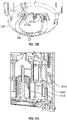
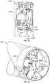
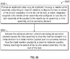
- the applicator includes an applicator housing, a needle carrier assembly, which includes an insertion element configured to insert a sensor of the on-skin sensor assembly into the skin of the host, a holder releasably coupled to the needle carrier assembly and configured to guide the on-skin sensor assembly while coupled to the needle carrier assembly, and a drive assembly configured to drive the insertion element from a proximal starting position to a distal insertion position, and from the distal insertion position to a proximal retraction position.
- the on-skin sensor assembly includes an electronics unit. In some embodiments, the sensor is connected to the electronics unit in the applicator housing. In some embodiments, the holder is configured to release the on-skin sensor assembly after the sensor is inserted at least partially into the skin of the host.
- the applicator further includes an activation element configured to activate the drive assembly. In some embodiments, the activation element includes a deflectable feature. In some embodiments, the deflectable feature is configured to provide resistance to activation. In some embodiments, the deflectable feature is configured to return the activation element to a starting position. In some embodiments, the activation element includes one of a button, a switch, a toggle, a slide, a trigger, and a knob.
- the applicator further includes a safety element configured to prevent operation of the activation element.
- the safety element includes a tab coupled to the activation element by at least one frangible member.
- the distal direction and the proximal direction extend along an insertion axis of the insertion element.
- the holder includes an elastomer.
- the applicator housing includes a guide.
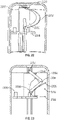
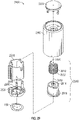
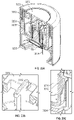
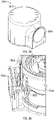
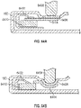
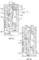
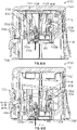
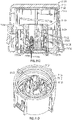
- the drive assembly includes a rotating drive element coupled to the needle carrier assembly and includes a pin configured to travel in the guide during rotation of the rotating drive element, and a spring configured to, upon activation of the drive assembly, rotate the rotating drive element in a single rotational direction thereby driving the insertion element from the proximal starting position to the distal insertion position, and from the distal insertion position to the proximal retraction position.
- the rotating drive element is configured to convert rotational motion into linear motion.
- the rotating drive element includes a wheel cam.
- the pin is radially offset from an axis of rotation of the rotating drive element.
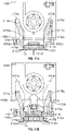
- the pin is positioned approximately 30 degrees from a bottom center orientation relative to the axis of rotation of the rotating drive element when the insertion element is in the proximal starting position. In some embodiments, the pin is positioned approximately 180 degrees from a bottom center orientation relative to the axis of rotation of the rotating drive element when the insertion element is in the distal insertion position. In some embodiments, the pin is positioned approximately 330 degrees from a bottom center orientation relative to the axis of rotation of the rotating drive element when the needle carrier assembly is in the proximal retracted position. In some embodiments, the pin travels in the guide in a direction perpendicular to a direction of extension of the insertion element. In some embodiments, the guide includes a slot.
- the slot is stationary during sensor insertion.
- the slot includes a horizontal slot.
- the slot includes a vertical slot configured to receive at least the pin of the rotating drive element when loaded through a bottom of the applicator housing.
- the applicator housing is stationary.
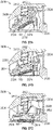
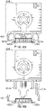
- the rotating drive element further includes a protrusion in contact with a retention element configured to prevent the rotating drive element from rotating.
- the applicator further includes an activation element configured to deflect the retention element, thereby allowing the rotating drive element to rotate.
- the rotating drive element further includes a protrusion configured to decouple the on-skin sensor assembly from the needle carrier assembly.
- the protrusion is configured to apply a force to the on-skin sensor assembly during rotation of the rotating drive element.
- the protrusion of the rotating drive element is configured to pass through a slot in the needle carrier assembly as the rotating drive element rotates.
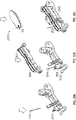
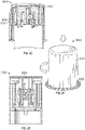
- the drive assembly includes a torsion spring.
- the torsion spring includes a first end coupled to the applicator housing, and a second end coupled to the needle carrier assembly.
- the first end and the second end unwind in opposite directions, thereby driving the insertion element from the proximal starting position to the distal insertion position, and from the distal insertion position to the proximal retraction position.
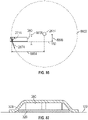
- the first end and the second end unwinding in opposite directions drives the torsion spring in an arc.
- the arc extends in a direction perpendicular to the distal direction and the proximal direction.
- a spool coupled to the torsion spring.
- the torsion spring is wrapped around the spool. In some embodiments, the second end of the torsion spring is configured to drive the insertion element. In some embodiments, the torsion spring is a double torsion spring. In some embodiments, the first end of the torsion spring is coupled to a protrusion of the applicator housing. In some embodiments, the second end of the torsion spring is coupled to a protrusion of the needle carrier assembly.
- the drive assembly further includes a linkage element, which includes a first end coupled to the first end of the torsion spring, a second end coupled to the second end of the torsion spring, and a hinge substantially aligned with a winding axis of the torsion spring.
- the linkage element includes a flexible linkage.
- the drive assembly includes a linkage element, which includes a first end coupled to the applicator housing, a second end coupled to the needle carrier assembly, and a hinge disposed between the first end and the second end.
- the drive assembly further includes a torsion spring, which includes a first end coupled to the needle carrier assembly, and a second end coupled to the linkage element between the second end and the hinge.
- the second end is configured to drive the linkage element such that the insertion element is driven from the proximal starting position to the distal insertion position, and from the distal insertion position to the proximal retracted position.
- the drive assembly includes a linkage element, which includes a first end coupled to the applicator housing, a second end coupled to the needle carrier assembly, and a hinge disposed between the first end and the second end.
- the drive assembly further includes a torsion spring, which includes a first end coupled to the applicator housing, and a second end coupled to the linkage element between the first end and the hinge.
- the second end Upon activation of the drive assembly, the second end is configured to drive the linkage element such that the insertion element is driven the proximal starting position to the distal insertion position, and from the distal insertion position to the proximal retracted position.
- the drive assembly includes a linkage element, which includes a first end coupled to the applicator housing, a second end coupled to the needle carrier assembly, and a hinge disposed between the first end and the second end.
- the drive assembly further includes an extension spring coupled to the linkage element. Upon activation of the drive assembly, the extension spring is configured to drive the linkage element such that the insertion element is driven in the distal direction to the distal insertion position and in the proximal direction from the distal insertion position.
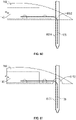
- the drive assembly includes a leaf spring, which includes a first end coupled to the applicator housing, and a second end coupled to the needle carrier assembly. Upon activation of the drive assembly, the leaf spring is configured to decompress, thereby driving the insertion element at least in the distal direction to the distal insertion position.
- the drive assembly includes a linkage element, which includes a first end coupled to the applicator housing, a second end coupled to the needle carrier assembly, and a hinge disposed between the first end and the second end.
- the drive assembly further includes a leaf spring, which includes a first end coupled to the needle carrier assembly, and a second end coupled to the linkage element between the second end and the hinge. Upon activation of the drive assembly, the leaf spring is configured to decompress, thereby driving the insertion element in the distal direction to the distal insertion position and in the proximal direction from the distal insertion position.
- the drive assembly includes a leaf spring, which includes a first end coupled to the applicator housing, and a second end coupled to the needle carrier assembly. Upon activation of the drive assembly, the leaf spring is configured to decompress, thereby driving the insertion element at least in the distal direction to the distal insertion position.
- the drive assembly includes a linkage element, which includes a first end coupled to the applicator housing, a second end coupled to the needle carrier assembly; and a hinge disposed between the first end and the second end.
- the drive assembly further includes a leaf spring, which includes a first end coupled to the needle carrier assembly, and a second end coupled to the linkage element between the second end and the hinge. Upon activation of the drive assembly, the leaf spring is configured to decompress, thereby driving the insertion element in the distal direction to the distal insertion position and in the proximal direction from the distal insertion position.
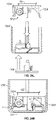
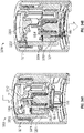
- the drive assembly includes an insertion spring configured to, upon activation of the drive assembly, drive the insertion element in the distal direction to the distal insertion position, and a retraction spring in contact with the needle carrier assembly and configured to drive the insertion element from the distal insertion position to the proximal retracted position.
- the insertion spring includes a compression spring.
- the retraction spring includes a leaf spring.
- the retraction spring is configured retract the insertion element from the skin of the host.
- a portion of energy stored in the insertion spring is transferred to the retraction spring as the insertion spring drives the insertion element in the distal direction.
- the insertion spring includes a first end coupled to the applicator housing and a second end coupled to the holder, and the holder is coupled to the needle carrier assembly while the insertion spring drives the insertion element in the distal direction to the distal insertion position and decoupled from the needle carrier assembly when the retraction spring drives the insertion element in the proximal direction from the distal insertion position.
- the insertion element is configured to travel in an arc when driven in the distal direction and in the proximal direction.
- the drive assembly includes a rotating drive element, which includes a ridge configured to slide along a channel in the needle carrier assembly, the ridge defining a variable cam path around at least a portion of a circumference of the rotating drive element, and a torsion spring configured to, upon activation of the drive assembly, rotate the rotating drive element thereby driving the insertion element in a distal direction to a distal insertion position and in a proximal direction from the distal insertion position based on the variable cam path.
- the torsion spring is configured to, upon activation of the drive assembly, rotate the rotating drive element in a single direction through an angle of greater than zero degrees and less than 360 degrees.
- the rotating drive element includes a barrel cam.
- the rotating drive element is configured to rotate in a plane substantially perpendicular to the proximal direction and the distal direction.
- the drive assembly includes a guide member coupled to the applicator housing, a hub configured to slide along the guide member, the hub in contact with a reverse toggling element through a first portion of travel along the guide member and in contact with the needle carrier assembly through a second portion of travel along the guide member.
- the reverse toggling element includes a fulcrum, a first end in contact with the hub through the first portion of travel along the guide member, and a second end coupled with the needle carrier assembly.
- the drive assembly further includes a spring configured to, upon activation of the drive assembly drive the hub in a proximal direction through the first portion of travel along the guide member, thereby driving the insertion element in the distal direction to the distal insertion position, and drive the hub in the proximal direction through the second portion of travel along the guide member, thereby driving the insertion element in the proximal direction from the distal insertion position.
- the drive assembly includes a first spring configured to, upon activation of the drive assembly, drive the needle carrier assembly in the distal direction to a distal insertion position, and a second spring configured to drive the needle carrier assembly in the proximal direction from the distal insertion position.
- the first spring and the second spring are precompressed before activation of the drive assembly.
- at least a portion of energy stored in the first spring is transferred to the second spring as the needle carrier assembly is driven in the distal direction to the distal insertion position.
- the holder includes at least one retention element configured to immobilize the holder to the applicator housing upon the needle carrier assembly reaching the distal insertion position.
- the holder further includes a retention element configured to releasably couple the on-skin sensor assembly to the holder as the needle carrier assembly travels in the distal direction to the distal insertion position, and decouple the on-skin sensor assembly from the holder as the needle carrier assembly travels in the proximal direction from the distal insertion position.
- the holder includes a retention element, which includes a first end and a second end.
- the first end is immobilized in a guide of the needle carrier assembly thereby releasably coupling the second end to the on-skin sensor assembly as the needle carrier assembly travels in the distal direction to the distal insertion position, and the first end is unseated from the guide of the needle carrier assembly thereby decoupling the second end from the on-skin sensor assembly as the needle carrier assembly travels in the proximal direction from the distal insertion position and separates from the holder.
- the needle carrier assembly includes a retention element releasably coupling the on-skin sensor assembly to the holder as the needle carrier assembly travels in the distal direction to the distal insertion position, and the retention element is configured to deform sufficiently to decouple from the on-skin sensor assembly as the needle carrier assembly travels in the proximal direction from the distal insertion position and separates from the holder.
- the holder includes a deformable retention element releasably coupling the on-skin sensor assembly to the holder, the needle carrier assembly in contact with the deformable retention element thereby preventing the deformable retention element from deforming as the needle carrier assembly travels in the distal direction to the distal insertion position.
- the needle carrier assembly separates from the holder as the needle carrier assembly travels in the proximal direction from the distal insertion position thereby allowing the retention element to deform sufficiently to decouple from the on-skin sensor assembly.
- the needle carrier assembly includes a first retention element configured to releasably couple the holder to the needle carrier assembly, and a second retention element configured to releasably couple the on-skin sensor assembly to one of the holder and the needle carrier assembly.
- the insertion element includes a C-needle having flared edges. In some embodiments, the insertion element includes a deflected-tip needle. In some embodiments, the insertion element includes a needle having a curvilinear profile configured to substantially track a path of insertion of the needle. In some embodiments, the insertion element includes a needle and the needle carrier assembly further includes a needle hub configured as a pass through for the needle during insertion of the sensor and is further configured to enclose a tip of the needle after insertion of the sensor. The insertion element further includes a needle spring configured to drive the needle hub to the tip of the needle after insertion of the sensor.
- the on-skin sensor assembly includes a fill port configured to receive a fluid or gel and a cannula configured to deliver the fluid or gel through the skin of the host.
- the applicator further includes an elastomeric sensor retention element coupled to the applicator housing at a first end and coupled to at least one of the insertion element and the sensor.
- the elastomeric sensor retention element is configured to retain the sensor within the insertion element prior to activation of the drive assembly.
- the insertion element is configured to progress in the proximal direction such that the elastomeric sensor retention element decouples from the at least one of the insertion element and the sensor.
- the applicator further includes a sensor retention element, which includes a tab configured to retain the sensor within the insertion element prior to activation of the drive assembly.
- the applicator further includes a sensor retention element disposed against at least one of the insertion element and the sensor in a first position and configured to rotate away from the insertion element and the sensor in a second position.
- the applicator further includes a sensor retention sleeve disposed around at least a portion of the insertion element and the sensor.
- the needle carrier assembly includes a tapered needle hub configured to split the sensor retention sleeve during insertion of the sensor.
- the senor includes a strain relief feature configured to limit the sensor from bending at a bend radius smaller than a predetermined bend radius.
- the strain relief feature includes an elastomeric material.
- the on-skin sensor assembly includes an open cavity configured to receive the sensor and provide an area for the sensor to bend from extending in a substantially horizontal direction to extending in a substantially vertical direction.
- the open cavity is configured to guide bodily fluid released from the host as a result of insertion of the sensor at least partially into the skin of the host.
- the on-skin sensor assembly includes a wicking material configured to absorb a bodily fluid released from the host as a result of insertion of the sensor at least partially into the skin of the host.
- a method for applying an on-skin sensor assembly to skin of a host includes providing an applicator, which includes an applicator housing, a needle carrier assembly includes an insertion element configured to insert a sensor of the on-skin sensor assembly into the skin of the host, a holder releasably coupled to the needle carrier assembly and configured to guide the on-skin sensor assembly while coupled to the needle carrier assembly and a drive assembly and an activation element.
- the method includes activating the activation element, wherein activating the activation element causes the drive assembly to drive the insertion element in a distal direction to a distal insertion position and in a proximal direction from the distal insertion position to a proximal retraction position, thereby inserting the sensor of the on-skin sensor assembly at least partially into the skin of the host.
- the distal direction and the proximal direction extend along an insertion axis of the insertion element.
- the applicator housing includes a guide.
- the drive assembly includes a rotating drive element coupled to the needle carrier assembly and includes a pin configured to travel in the guide during rotation of the rotating drive element, and a spring configured to, upon activation of the drive assembly, rotate the rotating drive element in a single rotational direction thereby driving the insertion element from the proximal starting position to the distal insertion position, and from the distal insertion position to the proximal retraction position.
- the rotating drive element is configured to convert rotational motion into linear motion.
- the rotating drive element includes a wheel cam.
- the pin is radially offset from an axis of rotation of the rotating drive element.
- the pin is positioned approximately 30 degrees from a bottom center orientation relative to the axis of rotation of the rotating drive element when the insertion element is in the proximal starting position. In some embodiments, the pin is positioned approximately 180 degrees from a bottom center orientation relative to the axis of rotation of the rotating drive element when the insertion element is in the distal insertion position. In some embodiments, the pin is positioned approximately 330 degrees from a bottom center orientation relative to the axis of rotation of the rotating drive element when the needle carrier assembly is in the proximal retracted position. In some embodiments, the guide includes a slot.
- the drive assembly includes a torsion spring
- the torsion spring includes a first end coupled to the applicator housing, and a second end coupled to the needle carrier assembly.
- the first end and the second end unwind in opposite directions, thereby driving the insertion element from the proximal starting position to the distal insertion position, and from the distal insertion position to the proximal retraction position.
- the first end and the second end unwinding in opposite directions drives the torsion spring in an arc.
- the arc extends in a direction perpendicular to the distal direction and the proximal direction.
- the drive assembly includes an insertion spring configured to, upon activation of the drive assembly, drive the insertion element in the distal direction to the distal insertion position, and a retraction spring in contact with the needle carrier assembly and configured to drive the insertion element from the distal insertion position to the proximal retracted position.
- the insertion spring includes a compression spring.
- the retraction spring includes a leaf spring.
- the insertion spring includes a first end coupled to the applicator housing and a second end coupled to the holder.
- the holder is coupled to the needle carrier assembly while the insertion spring drives the insertion element in the distal direction to the distal insertion position and decoupled from the needle carrier assembly when the retraction spring drives the insertion element in the proximal direction from the distal insertion position.
- the insertion element is configured to travel in an arc when driven in the distal direction and in the proximal direction.
- the drive assembly includes a rotating drive element, which includes a ridge configured to slide along a channel in the needle carrier assembly, the ridge defining a variable cam path around at least a portion of a circumference of the rotating drive element, and a torsion spring configured to, upon activation of the drive assembly, rotate the rotating drive element thereby driving the insertion element in a distal direction to a distal insertion position and in a proximal direction from the distal insertion position based on the variable cam path.
- the torsion spring is configured to, upon activation of the drive assembly, rotate the rotating drive element in a single direction through an angle of greater than zero degrees and less than 360 degrees.
- the rotating drive element includes a barrel cam.
- the rotating drive element is configured to rotate in a plane substantially perpendicular to the proximal direction and the distal direction.
- the drive assembly includes a guide member coupled to the applicator housing, a hub configured to slide along the guide member, the hub in contact with a reverse toggling element through a first portion of travel along the guide member and in contact with the needle carrier assembly through a second portion of travel along the guide member.
- the reverse toggling element includes a fulcrum, a first end in contact with the hub through the first portion of travel along the guide member, and a second end coupled with the needle carrier assembly;
- the drive assembly further includes a spring configured to, upon activation of the drive assembly, drive the hub in a proximal direction through the first portion of travel along the guide member, thereby driving the insertion element in the distal direction to the distal insertion position, and drive the hub in the proximal direction through the second portion of travel along the guide member, thereby driving the insertion element in the proximal direction from the distal insertion position.
- the drive assembly includes a first spring configured to, upon activation of the drive assembly, drive the needle carrier assembly in the distal direction to a distal insertion position, and a second spring configured to drive the needle carrier assembly in the proximal direction from the distal insertion position. In some embodiments, at least a portion of energy stored in the first spring is transferred to the second spring as the needle carrier assembly is driven in the distal direction to the distal insertion position.
- an applicator for applying an on-skin sensor assembly to a skin of a host includes an insertion assembly configured to translate a needle carrier assembly and the on-skin sensor assembly in a distal direction from an initial proximal position to a distal insertion position.
- the applicator includes a retraction assembly configured to translate the needle carrier assembly in a proximal direction from the distal inserted position to a proximal retracted position.
- the retraction assembly is configured to activate in response to the on-skin sensor assembly contacting the skin of the host.
- the insertion assembly includes a first spring. In some embodiments, the retraction assembly includes a second spring. In some embodiments, the insertion assembly further includes a holder configured to guide the needle carrier assembly at least during translation from the initial proximal position to the distal insertion position. In some embodiments, the holder further includes at least one retention element configured to retain the second spring at least during insertion. In some embodiments, the at least one retention element is disposed along an outside of the second coil and configured to contact and retain a coil of the second spring. In some embodiments, the needle carrier assembly further includes at least one backstop feature configured to prevent lateral deflection of the at least one retention element at least during insertion.
- the at least one backstop feature is configured not to contact the at least one retention element in the distal insertion position, thereby allowing the second spring to deflect the at least one retention element and activate the retraction assembly.
- the second spring is configured to exert a force sufficient to deflect the at least one retention element in the distal insertion position when the on-skin sensor assembly is in contact with the skin of the host.
- the applicator further includes an inner housing.
- the applicator further includes an outer housing including an activation element configured to activate the insertion assembly.
- the activation element is prevented from activating the insertion assembly until the outer housing is translated a predetermined distance in a distal direction with respect to the inner housing.
- the inner housing further includes an engagement element and the needle carrier assembly includes a protrusion.
- the engagement element is configured to engage with the protrusion upon the needle carrier assembly translating in a distal direction beyond a predetermined threshold, thereby preventing the needle carrier assembly from translating in the distal direction beyond the predetermined threshold.
- the engagement feature includes a hook.
- the needle carrier assembly further includes a hub configured to couple an insertion element to the needle carrier assembly.
- the hub is further configured to couple to the on-skin sensor assembly.
- the insertion assembly and the retraction assembly both include the first spring.
- the first spring is configured to exert a force between a holder and a deployment sleeve.
- the holder includes at least one retention element configured to immobilize the holder to the deployment sleeve.
- the applicator further includes a housing and an activation element configured to deflect the at least one retention element, thereby enabling the first spring to translate the holder, the needle carrier assembly and the on-skin sensor assembly from the proximal position to the distal insertion position.
- the housing further includes at least one protrusion
- the deployment sleeve includes at least one retention element configured to contact the at least one protrusion of the housing.
- the first spring is configured to exert a force sufficient to deflect the at least one retention element of the deployment sleeve when the on-skin sensor assembly is in contact with the skin of the host, thereby freeing the at least one retention element of the deployment sleeve from the at least one protrusion of the housing.
- the first spring is further configured to translate the deployment sleeve in the proximal direction.
- the needle carrier assembly further includes a protrusion configured to contact the deployment sleeve, thereby causing the needle carrier assembly to translate in the proximal direction.
- a needle hub for applying an on-skin sensor assembly to a skin of a host.
- the needle hub may include at least one upper arm.
- the needle hub includes a base comprising an anti-rotation feature.
- the base is configured to be at least partially disposed in an aperture of the on-skin sensor assembly.
- the needle hub is configured to couple with an insertion element.
- the anti-rotation feature is configured to prevent rotation of the base within the aperture.
- the anti-rotation feature includes a key having a shape complementary to at least a portion of the aperture.
- the at least one upper arm is configured to be disposed through an aperture in a needle carrier assembly of an applicator.
- the at least one upper arm is configured to contact an upper surface of the needle carrier assembly adjacent to the aperture in the needle carrier assembly.
- the at least one upper arm is configured to be disposed in a groove in the upper surface of the needle carrier assembly, thereby immobilizing the needle hub with respect to the needle carrier assembly.
- the at least one upper arm is flexible.
- the at least one upper arm is configured to flex radially inward.
- the needle hub further includes at least one lower arm.
- the at least one lower arm is configured to contact a lower surface of the needle carrier assembly adjacent to an aperture in the needle carrier assembly.
- the insertion element includes a needle.
- the needle includes an open side configured to receive a sensor of the on-skin sensor assembly.
- the base includes a flat surface configured to mate with a top surface of the on-skin sensor assembly, thereby maintaining the insertion element in a substantially perpendicular orientation to the top surface of the on-skin sensor assembly.
- a method for applying an on-skin sensor assembly to skin of a host includes providing an applicator.
- the applicator includes a housing comprising an activation element.
- the applicator includes an insertion assembly.
- the applicator includes a retraction assembly.
- the method includes activating the activation element. Activating the activation element causes the insertion assembly to translate a needle carrier assembly and the on-skin sensor assembly in a distal direction from a proximal position to a distal insertion position, thereby inserting a sensor of the on-skin sensor assembly at least partially into the skin of the host.
- Activating the activation element causes the retraction assembly to translate the needle carrier assembly in a proximal direction from the distal inserted position to a proximal retracted position.
- the retraction assembly is configured to activate in response to on-skin sensor assembly contacting the skin of the host.
- the insertion assembly includes a first spring. In some embodiments, the retraction assembly includes a second spring. In some embodiments, the insertion assembly further includes a holder configured to guide the needle carrier assembly at least during translation from the proximal position to the distal insertion position. In some embodiments, the holder further includes at least one retention element configured to retain the second spring at least during insertion. In some embodiments, the at least one retention element is disposed along an outside of the second coil and configured to contact and retain a coil of the second spring. In some embodiments, the needle carrier assembly further includes at least one backstop feature configured to prevent lateral deflection of the at least one retention element at least during insertion.
- the at least one backstop feature is configured not to contact the at least one retention element in the distal insertion position, thereby allowing the second spring to deflect the at least one retention element and activate the retraction assembly.
- the second spring is configured to exert a force sufficient to deflect the at least one retention element in the distal insertion position when the on-skin sensor assembly is in contact with the skin of the host.
- the second spring includes a tang extending along a diameter of second spring and wherein the at least one retention element is disposed along an inside of the second spring and configured to retain the tang of the second spring.
- the housing is an outer housing and the applicator further includes an inner housing.
- activating the activation element includes translating the outer housing a predetermined distance in a distal direction with respect to the inner housing.
- the inner housing further includes an engagement element and the needle carrier assembly includes a protrusion.
- the engagement element is configured to engage with the protrusion upon the needle carrier assembly translating in a distal direction beyond a predetermined threshold, thereby preventing the needle carrier assembly from translating in the distal direction beyond the predetermined threshold.
- the engagement feature includes a hook.
- the needle carrier assembly further includes a needle hub configured to couple the insertion element to the needle carrier assembly.
- the insertion assembly and the retraction assembly both include the first spring.
- the first spring is configured to exert a force between a holder and a deployment sleeve.
- the holder includes at least one retention element configured to immobilize the holder to the deployment sleeve.
- activating the activation element includes deflecting the at least one retention element of the holder, thereby enabling the first spring to translate the holder, the needle carrier assembly and the on-skin sensor assembly from the proximal position to the distal insertion position.
- the housing further includes at least one protrusion
- the deployment sleeve includes at least one retention element configured to contact the at least one protrusion of the housing.
- the first spring is configured to exert a force sufficient to deflect the at least one retention element of the deployment sleeve when the on-skin sensor assembly is in contact with the skin of the host, thereby freeing the at least one retention element of the deployment sleeve from the at least one protrusion of the housing.
- the first spring is further configured to translate the deployment sleeve in the proximal direction.
- the needle carrier assembly further includes a protrusion configured to contact the deployment sleeve, thereby causing the needle carrier assembly to translate in the proximal direction.
- an applicator for applying an on-skin sensor assembly to a skin of a host includes a first body releasably coupled to a needle.
- the applicator further includes a second body releasably coupled to the first body by a frictional engagement.
- the applicator further includes a spring configured to provide a first force to the first body and second body. The first force can drive the first body and second body in a distal direction.
- the frictional engagement can be configured to be decoupled by a counter force applied to the on-skin sensor assembly in an opposite direction of the first force.
- the applicator further includes at least one retention element configured to frictionally couple the second body to the first body.
- the at least one retention element is formed integral with the second body.
- the at least one retention element is frictionally engaged against a wall of the first body.
- the counter force decouples the frictional engagement by displacing the at least one retention element from the wall of the first body.
- the wall is a backstop. In some embodiments, the wall is configured to prevent the at least one retention element from deflecting.
- the frictional engagement is decoupled by the counter force exceeding a force threshold.
- the force threshold is determined by the frictional force between the at least one retention element and the first body.
- the threshold is at least 0.5 lbf. In some embodiments, the threshold is at least 1 lbf.
- the first body is configured to retract in a proximal direction upon decoupling of the frictional engagement.
- the applicator further includes a second spring.
- the second spring can be configured to drive the first body in a proximal direction.
- the second spring is retained from release by at least one retention element of the second body.
- the decoupling of the frictional engagement is configured to be independent of a distance between the on-skin sensor assembly and a distal end of the applicator.
- the first body is configured to retract independent of the distance between the on-skin sensor assembly and the distal end of the applicator.
- the counter force applied to the on-skin sensor assembly is provided by the skin of the host opposing the first force.
- an interior of the applicator is configured to allow the skin of the host to reside within the interior.
- the needle is configured to be inserted into the skin a predetermined depth.
- the frictional engagement is configured to decouple at a range of distances between the on-skin sensor assembly and a distal end of the applicator.
- FIG. 1 is a diagram depicting an example continuous analyte monitoring system 100 including an analyte sensor system 102 comprising an on-skin sensor assembly 160 configured to be fastened to the skin of a host via a base (not shown).
- Analyte sensor system 102 is operatively connected to a host and a plurality of display devices 110-114 according to certain aspects of the present disclosure.
- Example display devices 110-114 may include computers such as smartphones, smartwatches, tablet computers, laptop computers, and desktop computers.
- display devices 110-114 may be Apple Watches, iPhones, and iPads made by Apple Inc., or Windows or Google devices.
- display device 114 alternatively or in addition to being a display device, may be a medicament delivery device that can act cooperatively with analyte sensor system 102 to deliver medicaments to the host.
- Analyte sensor system 102 may include a sensor electronics module 140 and a continuous analyte sensor 138 associated with sensor electronics module 140.
- Sensor electronics module 140 may be in direct wireless communication with one or more of the plurality of display devices 110-114 via wireless communications signals.
- display devices 110-114 may also communicate amongst each other and/or through each other to analyte sensor system 102.
- wireless communications signals from analyte sensor system 102 to display devices 110-114 can be referred to as "uplink" signals 128.
- Wireless communications signals from, e.g., display devices 110-114 to analyte sensor system 102 can be referred to as "downlink" signals 130.
- Wireless communication signals between two or more of display devices 110-114 may be referred to as “crosslink” signals 132.
- wireless communication signals can include data transmitted by one or more of display devices 110-113 via "long-range" uplink signals 136 (e.g., cellular signals) to one or more remote servers 190 or network entities, such as cloud-based servers or databases, and receive long-range downlink signals 142 transmitted by remote servers 190.
- long-range uplink signals 136 e.g., cellular signals
- one of the plurality of display devices may be a custom display device 111 specially designed for displaying certain types of displayable sensor information associated with analyte values received from the sensor electronics module 126 (e.g., a numerical value and an arrow, in some embodiments).
- one of the plurality of display devices may be a handheld device 112, such as a mobile phone based on the Android, iOS operating system or other operating system, a palm-top computer and the like, where handheld device 112 may have a relatively larger display and be configured to display a graphical representation of the continuous sensor data (e.g., including current and historic data).
- Other display devices can include other hand-held devices, such as a tablet 113, a smart watch 110, a medicament delivery device 114, a blood glucose meter, and/or a desktop or laptop computer.
- display device 134e which may be a medicament delivery device in addition to or instead of a display device
- the alerts and/or sensor information provided by continuous analyte sensor 122 vis-à-vis sensor electronics module 126 can be used to initiate and/or regulate the delivery of the medicament to host 120.
- a sensing portion of sensor 138 may be disposed under the host's skin and a contact portion of sensor 138 can be electrically connected to electronics unit 140.
- Electronics unit 140 can be engaged with a housing (e.g., a base) which is attached to an adhesive patch fastened to the skin of the host.
- a housing e.g., a base
- electronics unit 140 is integrally formed with the housing.
- electronics unit 140 may be disposable and directly coupled to the adhesive patch.
- Continuous analyte sensor system 100 can include a sensor configuration that provides an output signal indicative of a concentration of an analyte.
- the output signal including e.g., sensor data, such as a raw data stream, filtered data, smoothed data, and/or otherwise transformed sensor data
- the output signal including (e.g., sensor data, such as a raw data stream, filtered data, smoothed data, and/or otherwise transformed sensor data) is sent to the receiver.
- analyte sensor system 100 includes a transcutaneous glucose sensor, such as is described in U.S. Patent Publication No. US-2011-0027127-A1 .
- sensor system 100 includes a continuous glucose sensor and comprises a transcutaneous sensor (e.g., as described in U.S. Pat. No. 6,565,509 , as described in U.S. Pat. No. 6,579,690 , and/or as described in U.S. Pat. No. 6,484,046 ).
- the sensor can extend through a housing, which can maintain sensor 138 on, in or under the skin and/or can provide for electrical connection of sensor 138 to sensor electronics in electronics unit 140.
- description of a base, a housing, a wearable, and/or a transmitter of on-skin sensor assembly 160 may be interchangeable.
- a base and a housing of on-skin sensor assembly 160 may be different in the sense that they may be separate components from sensor electronics module 140, e.g., from a transmitter or receiver.
- sensor 138 is in a form of a wire.
- a distal end of the wire can be formed, e.g., having a conical shape (to facilitate inserting the wire into the tissue of the host).
- Sensor 138 can include an elongated conductive body, such as an elongated conductive core (e.g., a metal wire) or an elongated conductive core coated with one, two, three, four, five, or more layers of material, each of which may or may not be conductive.
- the elongated sensor may be long and thin, yet flexible and strong.
- the smallest dimension of the elongated conductive body is less than 0.1 inches, less than 0.075 inches, less than 0.05 inches, less than 0.025 inches, less than 0.01 inches, less than 0.004 inches, less than 0.002 inches, less than 0.001 inches, and/or less than 0.0005 inches.
- Sensor 138 may have a circular cross section.
- the cross section of the elongated conductive body can be ovoid, rectangular, triangular, polyhedral, star-shaped, C-shaped, T-shaped, X-shaped, Y-shaped, irregular, or the like.
- a conductive wire electrode is employed as a core.
- sensor 138 may be disposed on a substantially planar substrate. To such an electrode, one or two additional conducting layers may be added (e.g., with intervening insulating layers provided for electrical isolation).
- the conductive layers can be comprised of any suitable material. In certain embodiments, it may be desirable to employ a conductive layer comprising conductive particles (i.e., particles of a conductive material) in a polymer or other binder.
- the materials used to form the elongated conductive body can be strong and hard, and therefore can be resistant to breakage.
- the ultimate tensile strength of the elongated conductive body is greater than 80 kPsi and less than 140 kPsi, and/or the Young's modulus of the elongated conductive body is greater than 160 GPa and less than 220 GPa.
- the yield strength of the elongated conductive body can be greater than 58 kPsi and less than 2200 kPsi.
- Electronics unit 140 can be releasably or permanently coupled to sensor 138.
- Electronics unit 140 can include electronic circuitry associated with measuring and processing the continuous analyte sensor data.
- Electronics unit 140 can be configured to perform algorithms associated with processing and calibration of the sensor data.
- electronics unit 140 can provide various aspects of the functionality of a sensor electronics module as described in U.S. Patent Publication No. US-2009-0240120-A1 and U.S. Patent Publication No. US-2012-0078071-A1 .
- Electronics unit 140 may include hardware, firmware, and/or software that enable measurement of levels of the analyte via a glucose sensor, such as sensor 138.
- electronics unit 140 can include a potentiostat, a power source for providing power to sensor 138, signal processing components, data storage components, and a communication module (e.g., a telemetry module) for one-way or two-way data communication between electronics unit 140 and one or more receivers, repeaters, and/or display devices, such as devices 110-114.
- Electronic components can be affixed to a printed circuit board (PCB), or the like, and can take a variety of forms.
- the electronic components can take the form of an integrated circuit (IC), such as an Application-Specific Integrated Circuit (ASIC), a microcontroller, and/or a processor.
- IC integrated circuit
- ASIC Application-Specific Integrated Circuit
- the electronics unit 140 may include sensor electronics that are configured to process sensor information, such as storing data, analyzing data streams, calibrating analyte sensor data, estimating analyte values, comparing estimated analyte values with time-corresponding measured analyte values, analyzing a variation of estimated analyte values, and the like. Examples of systems and methods for processing sensor analyte data are described in more detail in U.S. Pat. No. 7,310,544 , U.S. Pat. No. 6,931,327 , U.S. Patent Publication No. 2005-0043598-A1 , U.S. Patent Publication No. 2007-0032706-A1 , U.S. Patent Publication No.
- Electronics unit 140 may communicate with the devices 110-114, and/or any number of additional devices, via any suitable communication protocol.
- Example communication methods or protocols include radio frequency; Bluetooth; universal serial bus; any of the wireless local area network (WLAN) communication standards, including the IEEE 802.11, 802.15, 802.20, 802.22 and other 802 communication protocols; ZigBee; wireless (e.g., cellular) telecommunication; paging network communication; magnetic induction; satellite data communication; a proprietary communication protocol, open source communication protocol, and/or any suitable wireless communication method.
- WLAN wireless local area network
- Any sensor shown or described herein can be an analyte sensor; a glucose sensor; and/or any other suitable sensor.
- a sensor described in the context of any embodiment can be any sensor described herein .
- Sensors shown or described herein can be configured to sense, measure, detect, and/or interact with any analyte.
- analyte is a broad term, and is to be given its ordinary and customary meaning to a person of ordinary skill in the art (and is not to be limited to a special or customized meaning), and refers without limitation to a substance or chemical constituent in a biological fluid (for example, blood, interstitial fluid, cerebral spinal fluid, lymph fluid, urine, sweat, saliva, etc.) that can be analyzed.
- a biological fluid for example, blood, interstitial fluid, cerebral spinal fluid, lymph fluid, urine, sweat, saliva, etc.
- Analytes can include naturally occurring substances, artificial substances, metabolites, or reaction products.
- the analyte for measurement by the sensing regions, devices, systems, and methods is glucose.
- other analytes are contemplated as well, including, but not limited to ketone bodies; Acetyl Co A; acarboxyprothrombin; acylcarnitine; adenine phosphoribosyl transferase; adenosine deaminase; albumin; alpha-fetoprotein; amino acid profiles (arginine (Krebs cycle), histidine/urocanic acid, homocysteine, phenylalanine/tyrosine, tryptophan); andrenostenedione; antipyrine; arabinitol enantiomers; arginase; benzoylecgonine (cocaine); biotinidase; biopterin; c-reactive protein; carnitine; carnosinase; CD4; ceruloplasmin; chenodeoxycholic acid; chloroquine
- Salts, sugar, protein, fat, vitamins, and hormones naturally occurring in blood or interstitial fluids can also constitute analytes in certain embodiments.
- the analyte can be naturally present in the biological fluid or endogenous, for example, a metabolic product, a hormone, an antigen, an antibody, and the like.
- the analyte can be introduced into the body or exogenous, for example, a contrast agent for imaging, a radioisotope, a chemical agent, a fluorocarbon-based synthetic blood, or a drug or pharmaceutical composition, including but not limited to insulin; glucagon; ethanol; cannabis (marijuana, tetrahydrocannabinol, hashish); inhalants (nitrous oxide, amyl nitrite, butyl nitrite, chlorohydrocarbons, hydrocarbons); cocaine (crack cocaine); stimulants (amphetamines, methamphetamines, Ritalin, Cylert, Preludin, Didrex, PreState, Voranil, Sandrex, Plegine); depressants (barbiturates, methaqualone, tranquilizers such as Valium, Librium, Miltown, Serax, Equanil, Tranxene); hallucinogens (phencyclidine, lysergic acid, mescaline
- Analytes such as neurochemicals and other chemicals generated within the body can also be analyzed, such as, for example, ascorbic acid, uric acid, dopamine, noradrenaline, 3-methoxytyramine (3MT), 3,4-dihydroxyphenylacetic acid (DOPAC), homovanillic acid (HVA), 5-hydroxytryptamine (5HT), 5-hydroxyindoleacetic acid (FHIAA), and intermediaries in the Citric Acid Cycle.
- an adhesive to couple a base or housing, a sensor module, a transmitter or electronics unit, and/or a sensor to a host (e.g., to skin of the host).
- the adhesive can be configured for adhering to skin.
- the adhesive can include a pad (e.g., that is located between the adhesive and the base). Additional adhesive information, including adhesive pad information, is described in U.S. Patent Application No. 14/835,603, which was filed on August 25, 2015 .
- the on-skin sensor assembly may include a base that comprises an adhesive to couple a glucose sensor to the skin.
- Other methods are contemplated such as a strap, e.g., a watch band.
- any of the features described in the context of at least FIG. 1 can be applicable to all aspects and embodiments identified herein. Moreover, any of the features of an embodiment is independently combinable, partly or wholly with other embodiments described herein in any way, e.g., one, two, or three or more embodiments may be combinable in whole or in part. Further, any of the features of an embodiment may be made optional to other aspects or embodiments. Any aspect or embodiment of a method can be performed by a system or apparatus of another aspect or embodiment, and any aspect or embodiment of a system can be configured to perform a method of another aspect or embodiment.
- an on-skin sensor assembly which may also be described as a wearable.
- Such on-skin sensor assemblies may be disposable or reusable and may (see FIGs. 68-70 ) or may not (see FIGs. 2-4 ) comprise a base or base plate.
- on-skin sensor assemblies having a base plate e.g., FIGs. 68-70
- on-skin sensor assemblies without a base plate e.g., FIGs. 2-4
- FIG. 1 has already been discussed with respect to on-skin sensor assembly 160, FIGs . 2A-4 and 68-70 describe at least some other embodiments of an on-skin sensor assembly.
- FIG. 2A illustrates a perspective view of an on-skin sensor assembly 260, in accordance with some embodiments.
- On-skin sensor assembly 260 may comprise an outer housing comprising a first, top portion 292 and a second, lower portion 294.
- the outer housing may comprise a clamshell design.
- On-skin sensor assembly 260 may include similar components as electronics unit 140 described above in FIG. 1 (e.g.
- the outer housing may feature a large rounded body having tapered end opposite the large rounded body.
- the outer housing may further comprise an aperture 296 disposed at the tapered end of the outer housing and adapted for sensor 238 and needle insertion.
- Aperture 296 may be an opening featuring a U-shaped channel extending through the tapered end of the outer housing.
- On-skin sensor assembly 260 may further comprise an adhesive patch 226 configured to secure on-skin sensor assembly 260 to skin of the host.
- adhesive patch 226 may feature an aperture 298 having a similar shape as aperture 296 and substantially aligned with aperture 296.
- Sensor 238 may be configured to at least partially extend through apertures 296 and 298.
- adhesive patch 226 may comprise an adhesive suitable for skin adhesion, for example a pressure sensitive adhesive (e.g., acrylic, rubber-based, or other suitable type) bonded to a carrier substrate (e.g., spun lace polyester, polyurethane film, or other suitable type) for skin attachment, though any suitable type of adhesive is also contemplated.
- a pressure sensitive adhesive e.g., acrylic, rubber-based, or other suitable type
- carrier substrate e.g., spun lace polyester, polyurethane film, or other suitable type
- On-skin sensor assembly 260 may be attached to the host with use of an applicator adapted to provide convenient and secure application. Such an applicator may also be used for inserting sensor 238 through the host's skin, and/or connecting sensor 238 to the electronics unit. Once sensor 238 has been inserted into the skin (and is connected to the electronics unit), the sensor assembly can detach from the applicator.
- FIG. 2B illustrates a bottom perspective view of on-skin sensor assembly 260 of FIG. 2A.
- FIG. 2B illustrates aperture 296 disposed to a side of the outer housing, and aperture 298, each adapted for sensor 238 and needle insertion.
- FIG. 3A illustrates a perspective view of an on-skin sensor assembly 360, in accordance with some embodiments.
- On-skin sensor assembly 360 may comprise an outer housing comprising a first, top portion 392 and a second, lower portion 394.
- the outer housing may comprise a clamshell design.
- On-skin sensor assembly 260 may include similar components as electronics unit 140 described above in FIG. 1 (e.g.
- the outer housing may feature a generally oblong shape.
- the outer housing may further comprise an sensor assembly aperture 396 disposed substantially through a center portion of outer housing and adapted for sensor 338 and needle insertion through a bottom of on-skin sensor assembly 360.
- sensor assembly aperture 396 may be a channel or elongated slot.
- On-skin sensor assembly 360 may further comprise an adhesive patch 326 configured to secure on-skin sensor assembly 360 to skin of the host.
- adhesive patch 326 may comprise an adhesive suitable for skin adhesion on its underside, for example a pressure sensitive adhesive (e.g., acrylic, rubber-based, or other suitable type) bonded to a carrier substrate (e.g., spun lace polyester, polyurethane film, or other suitable type) for skin attachment, though any suitable type of adhesive is also contemplated.
- a pressure sensitive adhesive e.g., acrylic, rubber-based, or other suitable type
- carrier substrate e.g., spun lace polyester, polyurethane film, or other suitable type
- adhesive patch 326 may further comprise an adhesive on its topside, e.g., the non-skin contacting side to aid adherence of adhesive patch 326 to a portion of an associated applicator during manufacture and/or to maintain adhesive patch 326 in a substantially flat orientation before deployment to the skin of a host.
- the adhesive applied to the topside may be weaker than the adhesive applied to the underside to ensure appropriate transfer of the on-skin sensor assembly to the skin of the host.
- adhesive patch 396 may feature an aperture 398 aligned with sensor assembly aperture 396 such that sensor 338 may pass through a bottom of on-skin sensor assembly 360 and through adhesive patch 396.
- FIG. 3B illustrates a bottom perspective view of on-skin sensor assembly 360 of FIG. 3A.
- FIG. 3B further illustrates sensor assembly aperture 396 disposed substantially in a center portion of a bottom of on-skin sensor assembly 360, and aperture 398, both adapted for sensor 338 and needle insertion.
- FIG. 91 illustrates a perspective view of an on-skin sensor assembly 9160, according to some embodiments.
- On-skin sensor assembly 9160 may be substantially similar to other on-skin sensor assemblies described in this application, such as on-skin sensor assemblies 160, 260, and 360.
- On-skin sensor assembly 9160 may feature an adhesive patch 9126 and a clamshell design comprising a top shell and a bottom shell, similar to on-skin sensor assembly 360. Further, on-skin sensor assembly 9160 may include a plurality of attachment points 9162a and 9162b, similar to on-skin sensor assembly 160.
- On-skin sensor assembly 9160 may include an aperture 9296. Aperture 9296 may be a through-hole extending through on-skin sensor assembly 9160.
- Aperture 9296 may be configured to allow a needle and/or sensor to pass through.
- on-skin sensor assembly 9160 may further include an aperture 9294.
- Aperture 9294 may extend from a top surface of on-skin sensor assembly 9150 a certain depth through on-skin sensor assembly 9160.
- aperture 9294 is configured to engage with an anti-rotational feature such as base 7152 of needle hub 7150 described in FIG. 78 .
- on-skin sensor assembly 9160 includes an identification tag 9150.
- Identification tag 9150 may be located on a top surface of on-skin sensor assembly 9150 (as shown), or on a side surface of on-skin sensor assembly. Identification tag 9150 may be an image which resembles a logo or mark identifying the manufacturer of the on-skin sensor assembly. Additionally, identification tag 9150 may be configured to be scanned by a user to pair the on-skin sensor assembly with a device, such as handheld device 112.
- identification tag 9150 is a code such as, but not limited to, a QR code, a matrix code, a 2-D barcode, or a 3-D barcode. The code may be imbedded in the image of identification tag 9150.
- FIG. 4 illustrates a cross-sectional view of on-skin sensor assembly 360 of FIGs. 3A and 3B.
- FIG. 4 illustrates the first, top portion 392 and the second, bottom portion 394 of the outer housing, adhesive patch 326, sensor assembly aperture 396 in the center portion of on-skin sensor assembly 360, aperture 398 in the center portion of adhesive patch 326, and sensor 338 passing through sensor assembly aperture 396.
- the electronics unit previously described in connection with FIG. 3A , may further include a circuit board 404 and a battery 402 configured to provide power to at least circuit board 404.
- FIG. 87 illustrates a cross-sectional view of on-skin sensor assembly 360 of FIGs. 3A, 3B and 4 , further comprising an upper patch 328, according to some embodiments.
- Upper patch 328 may comprise an adhesive suitable for skin adhesion, device adhesion, or a combination thereof, on its underside, for example a pressure sensitive adhesive (e.g., acrylic, rubber-based, or other suitable type) bonded to a carrier substrate (e.g., spun lace polyester, polyurethane film, or other suitable type) for skin and/or device attachment, though any suitable type of adhesive is also contemplated.
- a pressure sensitive adhesive e.g., acrylic, rubber-based, or other suitable type
- carrier substrate e.g., spun lace polyester, polyurethane film, or other suitable type
- such an adhesive may be the same as the adhesive applied to the underside of patch 326.
- the adhesive may be different from the adhesive applied to the underside of patch 326.
- upper patch 328 may be shaped as a circle, oval, partial strip, as an X, or as any other shape or form suitable for securing upper patch 328 to lower patch 326 and/or the skin of the host.
- the upper patch 328 may fully or partially cover on-skin sensor assembly 360.
- the upper patch 328 may improve adhesion lifespan of on-skin sensor assembly 360 on skin 130 of the host by adding additional adhesive contact area to the surface of the skin 130 and/or providing a single surface covering the wearable that reduces the risk of inadvertent mechanical removal (e.g.
- reducing surfaces of on-skin sensor assembly 360 may improve catch resistance.
- Such increased wearable lifespan provided by upper patch 328 may be a valuable property, especially as systems move toward and beyond 10-14 day wearable adhesion solutions.
- upper patch 328 may be assembled into any applicator in this description, above on-skin sensor assembly 360, with underside adhesive exposed.
- patch 326 may adhere to skin 130 of the host and upper patch 328 may be adhered over on-skin sensor assembly 360 and onto skin 130 of the host by one or more features of the applicator, for example, a holder and/or needle carrier assembly as described in connection with any figure herein.
- FIG. 5 illustrates an exploded perspective view of an applicator 500 for applying on-skin sensor assembly 160 to skin 130 of a host, according to some embodiments.
- applicator 500 may include an applicator housing 502 having an opening at its bottom and configured to house at least one or more mechanisms utilized to apply on-skin sensor assembly 160 to skin 130 of a host.
- Applicator housing 502 may be formed of any suitable material, e.g., a polymer, polycarbonate, ABS, nylon, polyethylene, polypropylene, etc.
- applicator housing 502 may be configured to cover at least one feature of applicator housing 502, for example a guide of a reciprocating or back and forth mechanism, e.g., a scotch-yoke mechanism (see FIG. 6B ).
- a reciprocating or back and forth mechanism e.g., a scotch-yoke mechanism (see FIG. 6B ).
- Applicator 500 includes an activation element 504 configured to activate a drive assembly of applicator 500.
- activation element 504 may be a button, a switch, a toggle, a slide, a trigger, a knob, a rotating member, a component that deforms and/or flexes or any other suitable mechanism for activating a drive assembly of applicator 500.
- Applicator 500 may further comprise a needle carrier assembly 508, including an insertion element (not shown in FIG. 5 ) configured to insert sensor 138 of on-skin sensor assembly 160 (e.g., FIG. 1 ) at least partially into skin 130 of the host.
- the insertion element is further illustrated in FIG. 6H as attaching to needle carrier assembly 508 and extending in the distal direction, substantially along an axis of insertion.
- needle carrier assembly 508 comprises a needle carrier or shuttle.
- the insertion element comprises a needle, for example, an open sided-needle, a deflected-tip needle with a deflected-tip, a curved needle, a polymer-coated needle, a hypodermic needle, or any other suitable type of needle or structure, as will be described in more detail in connection with at least FIGs . 47-50 and 80A-B .
- insertion element may comprise sensor 138 itself, sufficiently rigid to be inserted partially into skin 130 of the host with minimal or no structural support, such as described in U.S. Patent No. 9,357,951, which was filed on September 29, 2010 , U.S. Patent Publication No. US 2014/0107450, which was filed on February 28, 2013 , and U.S. Patent Publication No. US 2015/0289788, which was filed on April 10, 2014 .
- Applicator 500 may further comprise a drive assembly 510 configured to drive the insertion element of needle carrier assembly 508 in a distal direction to a distal insertion position and in a proximal direction from the distal insertion position to a proximal retraction position.
- a distal direction may be defined as extending towards an open-ended side of the applicator 500 along a path needle carrier assembly 508 is configured to travel.
- the distal direction may also be defined as towards the skin of a user.
- a proximal direction may be defined as a direction extending in a substantially opposite direction from the distal direction. In some embodiments, the distal direction and the proximal direction extend along an insertion axis of the insertion element and of needle carrier assembly 508.
- Drive assembly 510 may include a rotating drive element 514 coupled to needle carrier assembly 508 via an axle 526.
- rotating drive element 514 comprises a cam feature, e.g., a wheel cam, having a substantially circular or ovoid circumference.
- Rotating drive element 514 may be configured to rotate with respect to needle carrier assembly 508 about an axis of rotation 518 coincident with a centerline of axle 526.
- Rotating drive element 514 may further include a pin 516 disposed at a position on a face of rotating drive element 514 displaced radially from axis of rotation 518. Pin 516 is configured to travel in a guide (see FIG. 6B ) of applicator housing 502.
- Drive assembly 510 may further include a spring 512.
- Spring 512 may be a torsion spring, a clock spring, a power spring, or any other suitable type of spring.
- Spring 512 may be formed of any suitable material including but not limited to plastic or metal, e.g., stainless steel.
- spring 512 is pre-compressed before activation of the applicator.
- spring 512 is configured to be additionally loaded during activation of the applicator.
- Spring 512 may have a first end 520 coupled to needle carrier assembly 508 and a second end 522 coupled to rotating drive element 514. Spring 512 may be disposed coaxially with axle 526.
- Spring 512 may be configured to, upon activation of drive assembly 510, rotate rotating drive element 514 in a single direction with respect to needle carrier assembly 508. In some embodiments, spring 512 is configured, upon activation of drive assembly 510, to unwind by rotating greater than zero degrees and less than 360 degrees. In some embodiments, spring 512 is pre-wound between 30 and 1440 degrees.
- rotating drive element 514 By virtue of rotating drive element 514 being configured to rotate with respect to needle carrier assembly 508, about axis of rotation 518, and pin 516 being restrained to travel in the guide of applicator housing 502, rotational motion of rotating drive element 514, driven by spring 512, is converted into linear, reciprocating motion of needle carrier assembly 508 along axis 590 and, therefore, of the insertion element (not shown). More specifically, rotation of rotating drive element 514 drives insertion element 508 in the distal direction to the distal insertion position and in the proximal direction from the distal insertion position to the proximal retraction position.
- Such embodiments may be able to omit handoff mechanisms between aspects of drive assembly 510 that separately drive the needle carrier assembly 508 in the distal and proximate directions by virtue of a single mechanism that converts rotational motion into reciprocating linear motion.
- Applicator 500 may further include a holder 524 releasably coupled to needle carrier assembly 508 and configured to guide on-skin sensor assembly 160 while coupled to needle carrier assembly 508.
- holder 524 may also be referred to as a carrier or transport member.
- FIG. 6A-6H illustrates cutaway and perspective views of several features of applicator 500 of FIG. 5 , according to some embodiments.
- FIG. 6A illustrates a cutaway view of applicator 500 including applicator housing 502, activation element 504, needle carrier assembly 508, rotating drive element 514, pin 516, and holder 524.
- Each of these components may have functionality as previously described in connection with at least FIG. 5 .
- FIG. 6B illustrates guide 582 in applicator housing 502.
- guide 582 may comprise a scotch-yoke track in which pin 516 is configured to travel upon activation of drive assembly 510, as rotating drive element 514 rotates.
- FIG. 6C illustrates a plurality of tracks 622a, 622b, 622c in applicator housing 502 in which a respective one of a plurality of protrusions or ribs 624a, 624b, 624c of needle carrier assembly 508 are configured to slide. Accordingly, tracks 622a-622c in applicator housing 502 define a path of travel for needle carrier assembly 508. In some embodiments, this path of travel is substantially linear and longitudinal. Although three tracks and protrusions are shown in FIG. 6C , any number of tracks and respective protrusions are contemplated. For ease of understanding, FIG. 6C illustrates a partial bottom view of applicator 500, which also shows portions of on-skin sensor assembly 160 and holder 524.
- FIG. 6D illustrates an embodiment where needle carrier assembly 508 comprises a locking element 632 configured to prevent rotating drive element 514 from rotating.
- rotating drive element 514 comprises a protrusion 634 in contact with retention element 632, which prevents protrusion 634 from traveling in a path it would otherwise take as spring 512 releases at least a portion of its stored energy in rotating drive element 514.
- retention element 632 comprises a deflectable tab formed of a material such as a polymer, polycarbonate, ABS, nylon, polyethylene, polypropylene, or any other suitable material.
- Activation element 504 comprises a protrusion 640 configured to deflect retention element 632 such that protrusion 634 is no longer held by retention element 632, thereby allowing rotating drive element 514 to rotate and activating drive assembly 510.
- Rotating drive element 514 further comprises a ridge 636 configured to limit rotation of rotating drive element 514 as rotating drive element 514 rotates and ridge 636 comes in contact with retention element 632.
- FIG. 6E illustrates a retention element 642 of holder 524 and a stop element 644 of applicator housing 502 configured to immobilize holder 524 to applicator housing 502 upon needle carrier assembly 508 reaching the distal insertion position.
- retention element 642 is a deflectable arm, or any other type of protrusion or snap. For example, as needle carrier assembly 508 travels in the distal direction, as a result of spring 512 turning rotating drive element 514, retention element 642 slides along an inside surface of applicator housing 502 until retention element 642 is slightly deflected by stop element 644, then snapping in an outward direction under stop element 644.
- needle carrier assembly 508 may be free to progress in the proximal direction as a result of spring 512 further turning rotating drive element 514. Stop element 644 will prevent retention element 642, and so holder 524, from traveling in the proximal direction. In this way, movement of needle carrier assembly 508 in the proximal direction, after reaching the distal insertion position, releases holder 524 from needle carrier assembly 508 and/or on-skin sensor assembly 160.
- FIG. 6F illustrates a protrusion 652 of holder 524 and a protrusion 654 of applicator housing 502 configured to prevent holder 524 from travelling beyond the distal insertion position in the distal direction.
- protrusion 652 travels along an inside surface of the applicator housing 502 until protrusion 652 comes in contact with protrusion 654, at which point holder 524 is prevented from further travel in the distal direction.
- FIG. 6G illustrates on-skin sensor assembly 160 including a plurality of attachment points 662a-662f configured to mate with respective retention elements on needle carrier assembly 508 and/or holder 524 while traveling at least partially toward the distal insertion position, in the distal direction, during applicator activation.
- attachment points 662a-662f are small grooves or indentations.
- the respective retention elements may comprise snap fits, friction fits, interference features, elastomeric grips and/or adhesives configured to couple on-skin sensor assembly 160 with needle carrier assembly 508 and/or holder 524.
- on-skin sensor assembly 160 may have at least a portion formed with a reduced thickness or a second material (e.g. an elastomer) and, therefore, reduced strength and rigidity, such that when applicator 500 is exposed to such pressure fluctuations, the portions having the reduced thickness or second material deform in a controlled manner, thereby reducing or eliminating damage that would otherwise occur to on-skin sensor assembly 160 due to undesirable uncontrolled expansion of on-skin sensor assembly 160.
- the portion formed with reduced thickness or a second material may be selected to direct controlled expansion away from datum and/or retention features securing the on-skin sensor assembly to applicator assembly. Such a feature may be present in any applicator described herein.
- FIG. 6H illustrates retention elements 672a, 672b of holder 528 configured to releasably couple on-skin sensor assembly 160 to holder 528 as needle carrier assembly 508 travels in the distal direction to the distal insertion position, and to decouple on-skin sensor assembly 160 from holder 528 as needle carrier assembly 508 travels in the proximal direction from the distal insertion position towards the proximal retraction position.
- retention elements 672a, 672b may each comprise a first end 676a, 676b, a second end 678a, 678b, and a pivot point 680a, 680b.
- first end 676a, 676b of each of retention elements 672a, 672b is immobilized in a respective guide 674a, 674b of needle carrier assembly 508 and each of retention elements 672a, 672b is immobilized against interference points 682a, 682b of needle carrier assembly 508, thereby releasably coupling second ends 678a, 678b to attachment points 662a, 662b of on-skin sensor assembly 160.
- guides 674a, 674b comprise a slot or a stop element.
- needle carrier assembly 508 Since retention elements 642, 644 and/or protrusions 652, 654 immobilize holder 524 at the distal insertion position (as described in FIG. 6E ), as needle carrier assembly 508 travels back in the proximal direction, needle carrier assembly 508 separates from holder 524, thereby separating first ends 676a, 676b of retention elements 672a, 672b from respective slots 674a, 674b, allowing first ends 676a, 676b to deflect inward and second ends 678a, 678b to deflect outward from attachment points 662a, 662b of on-skin sensor assembly 160 as retention elements 672a, 672b rotate about pivot points 680a, 680b.
- FIGs . 7A-7F illustrate several perspective views of the applicator of FIG. 5 in sequence, during operation, according to some embodiments.
- FIG. 7A illustrates a pre-activated state of applicator 500.
- Applicator housing 502 and slot 582 remain stationary with respect to the skin of the host during activation.
- Activation element 504 is in a pre-activation position.
- Insertion assembly 508 is also in a pre-activation position, coupled to holder 524, which is releasably coupled to on-skin sensor assembly 160, as described in connection with at least FIGs . 6A-6H .
- At least a portion of insertion element 674 of needle carrier assembly 508 is illustrated as protruding, in a distal direction, below on-skin sensor assembly 160.
- Insertion element 674 may comprises a needle, for example, an open sided-needle, a needle with a deflected-tip, a curved needle, a polymer-coated needle, a hypodermic needle, deflected-tip or any other suitable type of needle or structure, as will be described in more detail in connection with at least FIGs . 47-50 and 80A-B .
- Insertion element 674 may be configured to guide at least a portion of sensor 138 of on-skin sensor assembly 160.
- rotating drive element 514 of drive assembly 510 is shown in a pre-activation position, having pin 516 located at a first position within guide 582 of applicator housing 502, and having protrusion 634 in contact with retention element 632.
- pin 516 is positioned approximately 30 degrees (illustrated as clockwise, though counterclockwise is also contemplated) from a bottom dead center orientation relative to an axis of rotation of rotating drive element 514 that passes through a center of the face on which pin 516 is disposed.
- FIG. 7B illustrates a state of applicator 500 at activation.
- Activation element 504 is illustrated in an activated position, having been pushed longitudinally in the distal direction by a user, for example. In the activated position, activation element 504 deflects retention element 632 such that protrusion 634 of rotating drive element 514 is unimpeded from moving, thus allowing rotating drive element 514 to rotate by the unwinding of spring 512.
- FIG. 7B illustrates applicator 500 just at activation, rotating drive element 514, pin 516, needle carrier assembly 508, insertion element 674, holder 524 and on-skin sensor assembly 160 are still shown in their pre-activation orientations and locations as in FIG. 7A .
- rotating drive element 514 will rotate in the direction of the circular arrow, and needle carrier assembly 508, insertion element 674, holder 524 and on-skin sensor assembly 160 will be driven, by pin 516 under rotating drive element 514 rotation, in the distal direction to the distal insertion position.
- rotating drive element 514 may be configured to rotate in a direction opposite of the direction of the circular arrow.
- FIG. 7C illustrates a state of applicator 500 during activation.
- Activation element 504 is illustrated in the activated position of FIG. 7B .
- Rotating drive element 514 is shown as having rotated a portion of a revolution, indicated by the circular arrow, protrusion 634 having advanced beyond retention element 632.
- Pin 516 is shown as having moved to a second position within guide 582. This second position is shown as being to the left of the first, pre-activation position.
- Insertion assembly 508, insertion element 674, holder 524 and on-skin sensor assembly 160 are driven in the distal direction toward the distal insertion position when rotating drive element 514 is rotated by a force generated by spring 512.
- FIG. 7D illustrates applicator 500 during activation, in the distal insertion position.
- Activation element 504 is illustrated in the activated position of FIGs. 7B and 7C .
- Rotating drive element 514 is shown as having rotated clockwise further compared to FIG. 7C , indicated by the circular arrow, protrusion 634 having advanced yet further beyond retention element 632.
- Pin 516 is shown as having moved to a third position within guide 582, shown as being to the right of the first, pre-activation position and the second, activation position of FIG. 7C .
- Insertion assembly 508, insertion element 674, holder 524 and on-skin sensor assembly 160 are driven in the distal direction to the distal insertion position as rotating drive element 514 is further rotated by the force generated by spring 512.
- this distal insertion position at least a portion of insertion element 674 as well as at least a portion of sensor 138 of on-skin sensor assembly 160 may be inserted into skin 130 of the host.
- retention elements 642, 644 may be engaged and protrusions 652 and 654 (see FIG. 6 ) may be in contact with one another.
- pin 516 is positioned approximately 180 degrees (illustrated as clockwise, though counterclockwise is also contemplated) from the bottom dead center orientation relative to the axis of rotation of rotating drive element 514.
- FIG. 7E illustrates applicator 500 during activation.
- Activation element 504 is illustrated in the activated position of FIGs . 7B-7D .
- Rotating drive element 514 is shown as having rotated further compared to FIG. 7D , indicated by the circular arrow.
- Pin 516 is shown as having moved to a fourth position within guide 582. This fourth position is shown as being to the right of the first through third positions previously discussed.
- Insertion assembly 508 and insertion element 674 are now shown as being driven in the proximal direction from the distal insertion position as rotating drive element 514 is further rotated by the force generated by spring 512. Since retention elements 642, 644 (see FIG. 6 ) are engaged and protrusions 652 and 654 (see FIG.
- on-skin sensor assembly 160 may also be decoupled from holder 524, as previously described in connection with FIG. 6H .
- FIG. 7F illustrates applicator 500 post-activation.
- Activation element 504 is illustrated in the activated position of FIGs. 7B-7E .
- Rotating drive element 514 is shown as having rotated further compared to FIG. 7E , indicated by the circular arrow, such that ridge 636 is in contact with retention element 632, thereby restricting further rotation of rotating drive element 514.
- Pin 516 is shown as having moved to a fifth position within guide 582, which is shown as being to the left of the fourth, right-most position, as pin 516 travels back along guide 582.
- Insertion assembly 508 and insertion element 674 are shown in the proximal retraction position.
- Holder 524 and on-skin sensor assembly 160 are shown as separated from needle carrier assembly 508.
- on-skin sensor assembly 160 may also be decoupled from holder 524, as previously described in connection with FIG. 6H .
- pin 516 is positioned approximately 330 degrees (illustrated as clockwise, though counterclockwise is also contemplated) from the bottom center orientation relative to the axis of rotation of rotating drive element 514.
- FIGs . 8-10 illustrate cutaway views of applicators 800, 900, 1000 similar to applicator 500 of FIG. 5 , however, alternatively having activation elements 804, 904, 1004 disposed on an upper, medial, and lower side of, rather than on a top of, an applicator housing 802, 902, 1002, respectively.
- Applicators 800, 900, 1000 may comprise substantially all features of applicator 500 and have substantially the same operation.
- applicator housing 802, 902, 1002, activation element 804, 904, 1004, a needle carrier assembly 808, 908, 1008, a rotating drive element 814, 914, 1014, including a pin 816,916,1016 and a protrusion 834, 934, 1034 and a retention element 832, 932, 1032 may correspond substantially to applicator housing 502, activation element 504, needle carrier assembly 508, rotating drive element 514 including pin 516 and protrusion 504, and retention element 502 of applicator 500, respectively.
- activation element 804 is disposed on an upper side, rather than on a top, of applicator housing 802 and may be configured to, upon activation, deflect retention element 832 such that protrusion 834 no longer restrains rotating drive element 814 from rotating under force of a spring (not shown in FIG. 8 ) similar to spring 512 of applicator 500.
- activation element 904 is disposed on a medial side, rather than on a top, of applicator housing 902 and may be configured to, upon activation, deflect retention element 932 such that protrusion 934 no longer restrains rotating drive element 914 from rotating under force of a spring (not shown in FIG. 9 ) similar to spring 512 of applicator 500.
- retention element 932 may be located substantially on a side of rotating drive element 914.
- activation element 1004 is disposed on a lower side, rather than on a top, of applicator housing 1002 and may be configured to, upon activation, deflect retention element 1032 such that protrusion 1034 no longer restrains rotating drive element 1014 from rotating under force of a spring (not shown in FIG. 10 ) similar to spring 512 of applicator 500.
- retention element 1032 may be located substantially on a side of rotating drive element 1014. 50
- FIG. 11A illustrates coupling first end 520 of spring 512 to needle carrier assembly 508.
- First end 520 may be coupled to, or disposed against, a protrusion 1102 of needle carrier assembly 508 and spring 512 may be inserted around a hub 1104 of needle carrier assembly 508 such that spring 512 and hub 1104 are disposed coaxially with one another.
- FIG. 11B illustrates coupling second end 522 of spring 512 with rotating drive element 514 and inserting axle 526 into hub 1104 of needle carrier assembly 508 within which axle 526 may rotate.
- Axle 526, hub 1104, and spring 512 may be disposed coaxially with respect to one another.
- rotating drive element 514 may be rotated about axle 526 in a circular direction opposite of a direction that rotating drive element 514 rotates during activation, thereby pre-storing energy in spring 512.
- Axle 524 may be fully inserted into the portion of needle carrier assembly 508 such that protrusion 634 is in contact with retention element 632, thereby preventing rotating drive element 514 from rotating until activation.
- rotating drive element 514 may be rotated about axle 504 such that spring 512 is only partially wound. In such embodiments, spring 512 may be fully wound at a later stage of assembly.
- FIG. 11B illustrates rotating drive element 514 as having a male-type aspect configured to mate with a female-type aspect of hub 1104, the present disclosure also contemplates rotating drive element 514 as having a female-type aspect configured to mate with a male-type aspect of hub 1104.
- FIG. 11C illustrates pushing retention elements 672a, 672b toward a center of holder 524 and coupling holder 524 to needle carrier assembly 508 by seating first ends 676a, 676b of retention elements 672a, 672b into respective slots 674a, 674b of needle carrier assembly 508.
- FIG. 11D illustrates coupling on-skin sensor assembly 160 to holder 524 by snapping second ends 678a, 678b (not shown in FIG. 11D ) of retention elements 672a, 672b into attachment points 662a, 662b of on-skin sensor assembly 160.
- retention elements 672a, 672b may comprise snap fits, friction fits, interference features, elastomeric grips and/or adhesives.
- FIG. 11E illustrates inserting the assembled needle carrier assembly 508, rotating drive element 514, holder 524, and on-skin sensor assembly 160 into applicator housing 502 through the opening in the bottom of applicator housing 502 and through a vertical portion of guide 582 (see FIG. 11F ).
- pin 516 of rotating drive element 514 is inserted along at least the vertical portion of guide 582 in applicator housing 502, as shown in FIG. 11F .
- spring 512 (not shown in FIGs. 11E, 11F ) may not be fully wound at this point, instead being partially wound to the extent that pin 516 of rotating drive element 514 is positioned to be inserted along guide 582 in applicator housing 502.
- FIG. 11G illustrates positioning the assembled needle carrier assembly 508, rotating drive element 514, holder 524, and on-skin sensor assembly 160 further in the proximal direction into applicator housing 502 such that pin 516 of rotating drive element 514 follows guide 582 of applicator housing 502, thereby turning rotating drive element 514 fully winding spring 512 (not shown in FIG. 11G ) and positioning protrusion 634 in contact with retention element 632 such that the drive assembly, comprising at least rotating drive element 514, having pin 516, and spring 512, are loaded for activation.
- FIG. 11H illustrates a magnified cutaway view of area 1106 of FIG. 11G illustrating the relationship between rotating drive element 514, pin 516, guide 582, protrusion 634 and retention element 632.
- FIG. 11J illustrates inserting activation element 504 into applicator housing 502.
- FIG. 12 illustrates an exploded perspective view of another applicator 1200 for applying an on-skin sensor assembly to a skin of a host, according to some embodiments.
- Applicator 1200 may include an applicator housing 1202 having an opening in its bottom and configured to house at least one or more mechanisms utilized to apply on-skin sensor assembly 160 to skin 130 (see FIG. 2 ) of a host.
- Applicator 1200 includes an activation element 1204 configured to activate a drive assembly of applicator 1200.
- activation element 1204 may be a button, a switch, a toggle, a slide, a trigger, a knob, a rotating member, a component that deforms and/or flexes or any other suitable mechanism for activating a drive assembly of applicator 1200.
- Applicator 1200 may further comprise a needle carrier assembly 1208, including an insertion element (not shown in FIG. 12 ) configured to insert sensor 138 of on-skin sensor assembly 160 (e.g., FIG. 1 ) into skin 130 of the host.
- the insertion element comprises a needle, for example a C-needle, as will be described in more detail in connection with at least FIGs . 47-50 and 80A-B .
- Applicator 1200 may further comprise a drive assembly 1210 configured to drive the insertion element of needle carrier assembly 1208 in the distal direction to a distal insertion position and in the proximal direction from the distal insertion position to a proximal retraction position.
- a distal direction may be defined as extending towards an open-ended side of the applicator 1200 along a path needle carrier assembly 1208 is configured to travel. The distal direction may also be defined as towards the skin of a user.
- a proximal direction may be defined as a direction extending in a substantially opposite direction from the distal direction. In some embodiments, the distal direction and the proximal direction extend along an insertion axis of the insertion element and of needle carrier assembly 1208.
- Drive assembly 1210 may include a spring 1212 having a first tang 1220 (e.g., end) and a second tang 1222 (e.g., end).
- Spring 1212 may be a torsion spring, a double torsion spring, or any other suitable type of spring.
- Spring 1212 may be supported by a spring spool 1250 comprising a first portion 1250a and an optional second portion 1250b. In some embodiments, spring 1212 is self-supporting and is not supported by a spring spool.
- First portion 1250a may be configured to couple with second portion 1250b such that spring spool 1250 is disposed coaxially with spring 1212 and provides support for spring 1212 along an axis of rotation 1218 of spring 1212.
- first tang 1220 of spring 1212 may be coupled to applicator housing 1202, e.g., to a hook or protrusion of applicator housing 1202.
- Second tang 1222 may be coupled to needle carrier assembly 1208, e.g., a hook or protrusion of needle carrier assembly 1208.
- first tang 1220 and second tang 1222 of spring 1212 unwind in opposite clockwise or counterclockwise directions, thereby driving spring 1212 in an arc and insertion element 1208 in the distal direction to the distal insertion position and in the proximal direction from the distal insertion position.
- the arc through which drive assembly 1210 travels may extend in a direction approximately perpendicular to the distal direction and the proximal direction, or in an arc defined by the tangs of the spring and the rotation points.
- Applicator 1200 may further include a holder 1224 releasably coupled to needle carrier assembly 1208 and configured to guide on-skin sensor assembly 160 while coupled to needle carrier assembly 1208.
- holder 1224 may comprise a stripper plate.
- on-skin sensor assembly 160 may be stripped from holder 1224 and needle carrier assembly 1208 once on-skin sensor assembly 160 is disposed on skin 130 of the host.
- FIG. 13A-13F illustrate perspective and cutaway views of several features of applicator 1200 of FIG. 12 , according to some embodiments.
- FIG. 13A illustrates a cross-sectional view of applicator 1200, including applicator housing 1202 having retention element 1334, activation element 1204, spring spool 1250, spring 1212 having first tang 1220 and second tang 1222, needle carrier assembly 1208 having retention element 1332, holder 1224, and on-skin sensor assembly 160.
- retention element 1332 may comprise snap fits, friction fits, interference features, elastomeric grips and/or adhesives configured to couple on-skin sensor assembly 160 with needle carrier assembly 1208 and/or holder 1224.
- first tang 1220 is configured to, upon activation of the drive assembly, rotate about a rotation point 1336.
- Second tang 1222 is similarly configured.
- FIG. 13F illustrates a magnified perspective view of a retention element 1342 of holder 1224 and a stop element 1344 of applicator housing 1202 configured to immobilize holder 1228 to applicator housing 1202 upon needle carrier assembly 1208 reaching the distal insertion position.
- retention element 1342 is a deflectable arm. For example, as needle carrier assembly 1208 travels in the distal direction, as a result of spring 1212 partially unwinding, retention element 1342 slides along an inside surface of applicator housing 1202 and is deflected by stop element 1344 until retention element 1342 snaps under stop element 1344.
- the functionality between retention element 1342 and stop element 1344 may be swapped, e.g., stop element 1344 may be configured to be deflected by and snap over retention element 1342.
- stop element 1344 will prevent retention element 1342, and so holder 1224, from traveling back in the proximal direction. In this way, movement of needle carrier assembly 1208 in the proximal direction after reaching the distal insertion position allows holder 1224 and/or needle carrier assembly 1208 to be released from on-skin sensor assembly 160.
- FIG. 13B illustrates a magnified cutaway view of a portion of needle carrier assembly 1208 comprising a retention element 1332 configured to interlock with a retention element 1334 of applicator housing 1202 and prevent needle carrier assembly 1208 from separating from applicator housing 1202 in the loaded, pre-activated position.
- Activation element 1204 is configured to deflect retention element 1332 such that retention element 1334 no longer holds retention element 1332, thereby allowing spring 1212 to separate needle carrier assembly 1208 from applicator housing 1202 and activating drive assembly 1210.
- FIG. 13C illustrates a magnified view of second tang 1222 of a spring coupled to needle carrier assembly 1208, for example, via a hook 1348 configured to immobilize second tang 1222 to needle carrier assembly 1208.
- the fastening concept described for second tang 1222 in FIG. 13C may also be utilized for first tang 1220.
- FIG. 13D illustrates on-skin sensor assembly 160 including a plurality of attachment points 662a-662c configured to mate with respective retention elements 1372a-1372c on needle carrier assembly 1208 and/or holder 1224 while traveling in the distal direction at least partially toward the distal insertion position during applicator activation.
- holder 1224 comprises a stripper plate
- holder 1224 may function similarly to a stripper plate in punch and die manufacturing or injection molding processes.
- retention elements 1372a-1372c may comprise snap fits, friction fits, interference features, elastomeric grips and/or adhesives.
- Retention elements 1372a-1372c of needle carrier assembly 1208 and/or holder 1224 are configured to releasably couple on-skin sensor assembly 160 to holder 1228 as needle carrier assembly 1208 travels in the distal direction to the distal insertion position, and to decouple on-skin sensor assembly 160 from needle carrier assembly 1208 and/or holder 1228 as needle carrier assembly 1208 travels in the proximal direction from the distal insertion position towards the proximal retraction position.
- retention elements 1342, 1344 immobilize holder 1224 from traveling in the proximal direction at the distal insertion position, as needle carrier assembly 1208 travels back in the proximal direction.
- FIG. 13E illustrates a perspective view of a plurality of tracks 1322a, 1322b, 1322c in applicator housing 1202 in which a respective plurality of protrusions 1324a, 1324b, 1324c of needle carrier assembly 1208 are configured to slide. Accordingly, tracks 1322a-1322c in applicator housing 1202 define a path of travel for needle carrier assembly 1208. In some embodiments, this path of travel is substantially linear and longitudinal. Although three tracks and protrusions are shown in FIG. 13E , a single track or a plurality of tracks and respective protrusions are contemplated.
- FIGs. 14A-14E illustrate several cross-sectional views of the applicator of FIG. 12 during operation, according to some embodiments.
- FIG. 14A illustrates a state of applicator 1200 at activation.
- Activation element 1204 is illustrated in an activated position, having been pushed longitudinally in the distal direction by a user, for example. In the activated position, activation element 1204 deflects retention element 1332 such that retention element 1334 of applicator housing 1202 does not prevent needle carrier assembly 1208 from moving when spring 1212 unwinds from a pre-wound state.
- FIG. 14A illustrates applicator 1200 just at activation, spring 1212, needle carrier assembly 1208, holder 1224 and on-skin sensor assembly 160 are shown in their pre-activation orientations and locations. However, spring 1212 will unwind partially and needle carrier assembly 1208, holder 1224 and on-skin sensor assembly 160 will be driven, by such unwinding, in the distal direction to the distal insertion position.
- FIG. 14B illustrates a state of applicator 1200 during activation.
- Activation element 1204 is illustrated in the activated position of FIG. 14A .
- Spring 1212 has partially unwound such that first tang 1220 unwinds in a first arc-direction and second tang 1222 unwinds in a second arc-direction opposite of the first arc-direction.
- Spring 1212 travels through an arc-direction approximately perpendicular to the distal direction and the proximal direction, or in an arc defined by the tangs of spring 1212 and their associated rotation points.
- needle carrier assembly 1208, insertion element 1374, holder 1224 and on-skin sensor assembly 160 are driven in the distal direction toward the distal insertion position by a force generated by spring 1212.
- FIG. 14C illustrates applicator 1200 during activation, in a distal insertion position.
- Activation element 1204 is illustrated in the activated position of FIGs. 14A and 14B .
- Spring 1212 has unwound further, relative to its position as illustrated in FIGs. 14A and 14B , substantially in the direction of the horizontal arrow.
- Insertion assembly 1208, holder 1224 and on-skin sensor assembly 160 are driven in the distal direction to the distal insertion position by the force generated by spring 1212. In this distal insertion position, at least a portion of an insertion element coupled to needle carrier assembly 1208 similarly to that shown in FIG. 6 (not shown in FIGs.
- FIG. 14D illustrates applicator 1200 during activation.
- Activation element 1204 is illustrated in the activated position of FIGs. 14A-14C .
- Spring 1212 has further unwound and travelled in substantially the same direction as shown by the arrow.
- unwinding of spring 1212 in FIGs . 14A-14C caused movement of the needle carrier assembly 1208 in the distal direction, because spring 1212 is now on an opposite side of the points at which the first tang 1220 and the second tang 1222 are anchored, further unwinding of spring 1212 results in movement of the needle carrier assembly 1208 in the proximal direction toward the proximal retraction position. Since the retention elements (see FIG.
- on-skin sensor assembly 160 may also be decoupled from holder 1224, as previously described in connection with call-out 1330 of FIG. 13 .
- FIG. 14E illustrates applicator 1200 post-activation.
- Activation element 1204 is illustrated in the activated position of FIGs. 14A-14D .
- Spring 1212 is illustrated as having unwound further compared to its position as illustrated in FIG. 14D and having travelled substantially in the direction indicated by the arrow.
- Insertion assembly 1208 has travelled in the proximal direction indicated by the vertical arrow to the proximal retraction position.
- Holder 1224 and on-skin sensor assembly 160 are shown as separated from needle carrier assembly 1208.
- FIGs . 15-17 illustrate perspective views of several exemplary double torsional springs that support different configurations of applicator 1200, according to some embodiments. Accordingly, any of the springs described by FIGs . 15-17 may be utilized for spring 1212 previously discussed in connection with FIGs . 12-14E . As shown in FIGs . 15-17 , different shaped and/or sized cross-bridges 1522c, 1622c, 1722c of springs 1512, 1612, 1712 may be provided by flaring one or more tangs in a particular direction.
- FIGs . 15-17 illustrate double torsional springs 1512, 1612, 1712, each comprising a first winding 1512a, 1612a, 1712a and a second winding 1512b, 1612b, 1712b.
- Double torsional springs 1512, 1612, 1712 may be formed from a single segment of suitable material, e.g., metal or plastic.
- First windings 1512a, 1612a, 1712a each comprise a first tang 1520a, 1620a, 1720a and a second tang 1522a, 1622a, 1722a.
- Second windings 1512b, 1612b, 1712b each comprise a first tang 1520b, 1620b, 1720b and a second tang 1522b, 1622b, 1722b.
- second tangs 1522a, 1522b; 1622a, 1622b; 1722a, 1722b may be coupled to one another by a cross-bridge 1522c, 1622c, 1722c.
- Cross-bridge 1522c of FIG. 15 may have a length substantially equal to a spacing 1530 between first winding 1512a and second winding 1512b defined by the extension of second tangs 1522a, 1522b from first winding 1512a and second winding 1512b, respectively.
- Cross-bridge 1622c of FIG. 16 may have a length exceeding a spacing 1630 between first winding 1612a and second winding 1612b defined by the extension of second tangs 1622a, 1622b from first winding 1612a and second winding 1612b, respectively, due to second tang 1622b of second winding 1612b being flared toward first tang 1620b of second winding 1612b.
- 17 may have a length exceeding a spacing 1730 between first winding 1712a and second winding 1712b defined by the extension of second tangs 1722a, 1722b from first winding 1712a and second winding 1712b, respectively, due to second tang 1722a of first winding 1712a being flared toward first tang 1720a of first winding 1712a and second tang 1722b of second winding 1712b being flared toward first tang 1720b of second winding 1712b to provide the increased length of cross-bridge 1722c compared to either cross-bridge 1522c shown in FIG. 15 or cross-bridge 1622c shown in of FIG. 16 .
- FIGs . 18-23 illustrate alternative drive assemblies for utilization in applicators, such as applicator 1200 of FIG. 12 , according to some embodiments.
- FIG. 18 illustrates a drive assembly comprising a linkage element 1850.
- linkage element 1850 may comprise a flex linkage.
- the flex linkage may contain one or more living hinge(s).
- linkage element 1850 may comprise at least two discrete sections configured to pivot about a hinge coupling the at least two discrete sections.
- a flex linkage is a type of hinge assembly formed from an extension of a parent material (e.g., polypropylene plastic).
- the hinge flex linkage is a thin section of the parent material that acts as a bending connection with two larger sections of the parent material.
- the larger sections of the parent material as well as the hinge will be made of one continuous piece of the parent material. Since it is relatively thin and typically made from flexible materials, the flex linkage is also able to rotate about one axis by 180 degrees or more - potentially for many thousands or even millions of cycles. Contrary to most hinges, which involve multiple parts assembled in a traditional pivoting mechanism, flex linkages are not a separate entity. They may be described as a purposeful fault line at a predetermined point in the material which is designed such that it does not fail after repeated bending.
- Linkage element 1850 has a first end 1852 coupled to an applicator housing 1802, a second end 1854 coupled to a needle carrier assembly 1808, and a hinge 1856 disposed between first end 1852 and second end 1854.
- the drive assembly further comprises a spring 1812, which in some embodiments may be a single or double torsion spring.
- Spring 1812 comprises a first tang 1820 coupled to applicator housing 1802 and/or to linkage element 1850 at first end 1852 or at a position between first end 1852 and hinge 1856.
- Spring 1812 further comprises a second tang 1822 coupled to needle carrier assembly 1808 and/or to linkage element 1850 at second end 1854 or at a position between second end 1854 and hinge 1856.
- hinge 1856 may be aligned with an axis of rotation 1818 of spring 1812 to provide smooth operation as well as to reduce any stresses caused by incompatible movement between linkage element 1850 and spring 1812.
- Applicator 1200 may function substantially as described for applicator 1200 of FIG. 12 , however, further including that first end 1852, second end 1854 and hinge 1856 of linkage element 150 move substantially in alignment with first tang 1820, second tang 1822 and axis of rotation 1818 of spring 1812, respectively, during activation.
- FIG. 19 illustrates another drive assembly comprising a linkage element 1950.
- Linkage element 1950 has a first end 1952 coupled to an applicator housing 1902, a second end 1954 coupled to a needle carrier assembly 1908, and a hinge 1956 disposed between first end 1952 and second end 1954.
- the drive assembly further comprises a spring 1912, which in some embodiments may be a single or double torsion spring.
- Spring 1912 comprises a first tang 1920 coupled to linkage element 1950 between second end 1954 and hinge 1956.
- Spring 1912 further comprises a second tang 1922 coupled to needle carrier assembly 1908.
- spring 1912 Upon activation, spring 1912 unwinds and first tang 1952 sweeps an arc while second tang 1954 is held substantially stationary against needle carrier assembly 1908.
- first tang 1952 drives linkage element 1950 from the bent position shown, hinge 1956 pivoting, until linkage element 1950 is substantially vertical, and then continuing pivoting until linkage element 1950 is in a substantially mirror orientation from that shown in FIG. 19 .
- This motion drives needle carrier assembly 1908 in the distal direction, reaching the distal insertion position when linkage element 1950 is substantially vertical, and then increasingly in the proximal direction as linkage element 1950 is further driven from the substantially vertical orientation to the substantially mirrored orientation to that shown in FIG. 19 .
- FIG. 20 illustrates another drive assembly comprising a linkage element 2050.
- Linkage element 2050 has a first end 2052 coupled to an applicator housing 2002, a second end 2054 coupled to a needle carrier assembly 2008, and a hinge 2056 disposed between first end 2052 and second end 2054.
- the drive assembly further comprises a spring 2012, which in some embodiments may be a single or double torsion spring.
- Spring 2012 comprises a first tang 2020 coupled to linkage element 2050 between first end 2052 and hinge 2056.
- Spring 2012 further comprises a second tang 2022 coupled to applicator body 2002. Upon activation, spring 2012 unwinds and first tang 2052 sweeps an arc while second tang 2054 is held substantially stationary against applicator body 2002.
- first tang 2052 drives linkage element 2050 from the bent position shown, hinge 2056 pivoting, until linkage element 2050 is substantially vertical, and then continuing pivoting until linkage element 2050 is in a substantially mirror orientation from that shown in FIG. 20 .
- This motion drives needle carrier assembly 2008 in the distal direction, reaching the distal insertion position when linkage element 2050 is substantially vertical, and then increasingly in the proximal direction as linkage element 2050 is further driven from the substantially vertical orientation to the substantially mirrored orientation to that shown in FIG. 20 .
- FIG. 21 illustrates another drive assembly comprising a linkage element 2150.
- Linkage element 2150 has a first end 2152 coupled to an applicator housing 2102, a second end 2154 coupled to a needle carrier assembly 2108, and a hinge 2156 disposed between first end 2152 and second end 2154.
- the drive assembly further comprises a spring 2112, which in some embodiments may be an extension spring.
- a compression spring is also contemplated. However, a compression spring may be coupled between hinge 2156 and the closer side of applicator housing 2102.
- Spring 2112 comprises a first end 2120 coupled to linkage element 2150 and a second end 2122 coupled to applicator body 2102. In some embodiments, first end 2120 is coupled to linkage element 2150 between first end 2152 and hinge 2156.
- first end 2120 is coupled to linkage element 2150 at hinge 2156. In yet other embodiments first end 2120 is coupled to linkage element 2150 between hinge 2156 and second end 2154.
- spring 2112 Upon activation, spring 2112 unwinds through an arc that extends in a direction approximately perpendicular to the distal direction and the proximal direction, or in an arc defined by the tangs of the spring and their respective rotation points, driving linkage element 2150 from the bent position shown, hinge 2156 pivoting, until linkage element 2150 is substantially vertical, and then continuing pivoting until linkage element 2150 is in a substantially mirror orientation from that shown in FIG. 21 .
- This motion drives needle carrier assembly 2108 in the distal direction, reaching the distal insertion position when linkage element 2150 is substantially vertical, and then increasingly in the proximal direction as linkage element 2150 is further driven from the substantially vertical orientation to the substantially mirrored orientation to that shown in FIG. 21 .
- FIG. 22 illustrates another drive assembly comprising a leaf spring 2212.
- Leaf spring 2212 comprises a first end 2220 coupled to an applicator housing 2202 and a second end 2222 coupled to a needle carrier assembly 2208. Upon activation, leaf spring 2212 unloads in a direction substantially parallel to the axis of insertion, driving needle carrier assembly 2208 to the distal insertion position when leaf spring 2212 is unloaded.
- FIG. 23 illustrates another drive assembly comprising a linkage element 2350.
- Drive assembly 2310 is substantially the same as drive assembly 1910 except replacing torsion spring 1912 with leaf spring 2312.
- Linkage element 2350 has a first end 2352 coupled to an applicator housing 2302, a second end 2354 coupled to a needle carrier assembly 2308, and a hinge 2356 disposed between first end 2352 and second end 2354.
- the rive assembly further comprises leaf spring 2312 having a first end 2320 coupled to linkage element 2350 between second end 2354 and hinge 2356, and a second end 2322 coupled to needle carrier assembly 2308.
- spring 2312 unloads and first end 2320 sweeps an arc while second end 2322 is held substantially stationary against needle carrier assembly 2308.
- first end 2320 drives linkage element 2350 from the bent position shown, hinge 2356 pivoting, until linkage element 2350 is substantially vertical, and then continuing pivoting until linkage element 2350 is in a substantially mirror orientation from that shown in FIG. 23 .
- This motion drives needle carrier assembly 2308 in the distal direction, reaching the distal insertion position when linkage element 2350 is substantially vertical, and then increasingly in the proximal direction as linkage element 2350 is further driven from the substantially vertical orientation to the substantially mirrored orientation to that shown in FIG. 23 .
- FIGS. 24A-24M An example of steps for assembling an applicator such as applicator 1200 of FIG. 12 will now be discussed in connection with FIGS. 24A-24M . To the extent any step is compatible, the assembly steps of FIGS. 24A-24M may also apply to any applicator utilizing the drive assemblies described in connection with FIGS. 18-23 .
- FIG. 24A illustrates coupling first portion 1250a and second portion 1250b of spring spool 1250 together inside the windings of spring 1212.
- FIG. 24B illustrates the assembled spring spool 1250 and spring 1212.
- Spring spool 1250 and spring 1212 are disposed coaxially with one another.
- FIG. 24C illustrates spring 1212 before winding in the direction indicated by the circular arrow, having first tang 1220 and second tang 1222 in the illustrated positions.
- FIG. 24D illustrates spring 1212 after winding, having first tang 1220 and second tang 1222 in the illustrated positions.
- FIG. 24E illustrates coupling wound spring 1212 to needle carrier assembly 1208. In some embodiments, this includes coupling first tang 1220 to a hook 1348 of needle carrier assembly 1208 and coupling second tang 1222 to or disposing second tang 1222 against needle carrier assembly 1208.
- FIG. 24F illustrates a side view of wound spring 1212 coupled to needle carrier assembly 1208, while FIG. 24G illustrates a perspective view of the arrangement shown in FIG. 24F .
- FIG. 24H illustrates coupling holder 1224 to needle carrier assembly 1208 and on-skin sensor assembly 160 to holder 1224.
- FIG. 24J illustrates a side view of on-skin sensor assembly 160, holder 1224, and needle carrier assembly 1208 assembled, while FIG. 24K illustrates a perspective view of the arrangement shown in FIG. 24J .
- FIG. 24L illustrates assembling the complex including on-skin sensor assembly 160, holder 1224, needle carrier assembly 1208, and spring 1212 into applicator housing 1202 through the opening in the bottom of applicator housing 1202, and insertion of activation element 1204 into applicator housing 1202.
- FIG. 24M illustrates the result of the assembly shown in FIG. 24L .
- FIG. 25 illustrates an exploded perspective view of yet another applicator 2500 for on-skin sensor assembly 160 of an analyte sensor system, according to some embodiments.
- Applicator 2500 may include an applicator housing 2502 configured to house one or more mechanisms for applying on-skin sensor assembly 160 to skin 130 of a host.
- Applicator housing 2502 may be formed of any suitable material, e.g., a polymer, polycarbonate, ABS, nylon, polyethylene, polypropylene, etc.
- Applicator 2500 includes an activation element 2504 configured to activate a drive assembly of applicator 2500.
- activation element 2504 may be a button, a switch, a toggle, a slide, a trigger, a knob, a rotating member, a component that deforms and/or flexes or any other suitable mechanism for activating a drive assembly of applicator 2500.
- Applicator 2500 may further comprise a needle carrier assembly 2508, including an insertion element 2574 configured to insert sensor 138 (e.g., FIG. 1 ) of on-skin sensor assembly 160 (e.g., FIG. 1 ) into skin 130 (e.g., FIG. 1 ) of the host.
- insertion element 2574 comprises a needle, for example, an open sided-needle, a needle with a deflected-tip, a curved needle, a polymer-coated needle, a hypodermic needle, or any other suitable type of needle or structure, as will be described in more detail in connection with at least FIGS. 47-50 and 80A-B .
- insertion element may comprise sensor 138, sufficiently rigid to be inserted partially into skin 130 of the host with minimal or no structural support.
- Applicator 2500 may further comprise a drive assembly 2510 configured to drive insertion element 2574 of needle carrier assembly 2508 in a distal direction to a distal insertion position and in a proximal direction from the distal insertion position to a proximal retraction position.
- a drive assembly 2510 configured to drive insertion element 2574 of needle carrier assembly 2508 in a distal direction to a distal insertion position and in a proximal direction from the distal insertion position to a proximal retraction position.
- Applicator 2500 may further include a holder 2524 releasably coupled to needle carrier assembly 2508 and configured to guide on-skin sensor assembly 160 while coupled to needle carrier assembly 2508.
- on-skin sensor assembly 160 may be stripped from holder 2524 and needle carrier assembly 2508 once on-skin sensor assembly 160 is disposed on skin 130 of the host.
- Drive assembly 2510 may include a spring 2512, which may be any suitable type of spring, e.g., a compression spring, extension spring, leaf spring, flex arm spring, etc.
- Spring 2512 may have a first end 2520 coupled to applicator housing 2502 and a second end coupled to needle carrier assembly 2508.
- Spring 2520 may be configured to, upon activation of drive assembly 2510, drive needle carrier assembly 2508 in the distal direction.
- spring 2512 may be pre-loaded, e.g., at the factory. In some other embodiments, spring 2512 may be loaded by an action of the user of applicator 2500.
- Drive assembly 2510 further includes a spring 2528 that may be coupled to an applicator base 2530 of applicator 2500.
- spring 2528 may be a compression spring, extension spring, leaf spring, flex arm spring, etc.
- spring 2528 may be pre-loaded, e.g., at the factory.
- spring 2528 may be loaded by an action of the user.
- spring 2528 may be loaded by unloading of spring 2512.
- Spring 2528 may comprise one or more portions configured to drive needle carrier assembly 2508 in the proximal direction from the distal insertion position, as will be described in more detail below.
- FIG. 26A-26D illustrate several cutaway views and a bottom view of several features of applicator 2500 of FIG. 25 , according to some embodiments.
- FIG. 26A illustrates a perspective cutaway view of applicator 2500 including applicator housing 2502, activation element 2504, applicator base 2530 including protrusion 2602, spring 2512, leaf spring(s) 2528, needle carrier assembly 2508, holder 2524, and on-skin sensor assembly 160.
- Each of these components may have functionality as previously described in connection with at least FIG. 25 .
- FIG. 26B illustrates a perspective view of several features of holder 2524, applicator base 2530 and activation element 2504.
- Spring 2512 is configured to be coupled to applicator housing 2502 at a first end and to holder 2524 at a second end. In a pre-activation state, spring 2512 may be configured to store energy for driving holder 2512 (and needle carrier assembly 2508) in the distal direction to the distal insertion position upon activation.
- Holder 2524 comprises an axle 2614 configured to snap into applicator base 2530 such that holder 2524 is configured to pivot in a substantially circular arc about axle 2614.
- activation element 2504 is illustrated as comprising a protrusion 2612 configured to guide holder 2524 in the pre-activation position shown until activation element 2504 is activated, thereby displacing protrusion 2612 from its pre-activation orientation relative to holder 2524 and releasing holder 2524.
- FIG. 26B further illustrates that leaf spring(s) 2528 are not coupled to holder 2524. Instead, leaf spring(s) 2528 are coupled to needle carrier assembly 2508 and are configured to drive needle carrier assembly 2508 in the proximal direction from the distal insertion position.
- activation element 2504 is shown as a button, the present disclosure further contemplates activation element 2504 as a switch, a toggle, a slide, a trigger, a knob, a rotating member, a component that deforms and/or flexes or any other suitable mechanism for activating a drive assembly of applicator 2500.
- activation element 2504 is illustrated as being disposed on a side of applicator housing 2502, the present disclosure contemplates any other location, e.g., on a top, bottom, or other side location of applicator housing 2502, and/or any other angle of disposition with respect to applicator housing 2502.
- FIG. 26C illustrates an exploded perspective view of needle carrier assembly 2508, insertion element 2674, and holder 2524.
- Insertion element 2674 is coupled to needle carrier assembly 2508.
- insertion element 2674 comprises an open-sided needle configured to guide and insert sensor 138 of on-skin sensor assembly 160 (e.g., FIG. 1 ) into skin 130 of the host.
- Insertion assembly 2508 is coupled at a first end to axle 2614 of holder 2524.
- Insertion assembly 2508 further comprises a retention element 2622 configured to releasably couple a second end of needle carrier assembly 2508 to holder 2524.
- Insertion assembly 2508 further comprises a retention element 2604 configured to releasably couple on-skin sensor assembly 160 to needle carrier assembly 2508 and holder 2524.
- retention element 2604 may comprise a snap fit, friction fit, interference feature, elastomeric grip and/or adhesive configured to couple on-skin sensor assembly 160 with needle carrier assembly 2508 and/or holder 2524.
- Spring 2512 is configured to, upon activation of applicator 2500, drive needle carrier assembly 2508 and holder 2524 in the distal direction along a circular arc defined by axle 2614 to the distal insertion position. Spring 2512 transfers at least a portion of its stored energy to leaf spring(s) 2528 as needle carrier assembly 2508 is driven in the distal direction along the circular arc.
- leaf spring(s) 2528 may be pre-loaded such that spring 2512 does not transfer stored energy to leaf spring(s) 2528.
- a protrusion 2602 of applicator base 2530 is configured to deflect retention element 2622 sufficiently to separate needle carrier assembly 2508 from holder 2524 substantially at the distal insertion position, thereby uncoupling the second end of needle carrier assembly 2508 from holder 2524.
- leaf spring(s) 2528, now loaded are configured to drive needle carrier assembly 2508 in the proximal direction from the distal insertion position, along the circular arc, to the proximal retraction position.
- FIG. 26D illustrates a portion 2632 of activation element 2504 coupled to applicator housing 2502 and configured to act as a return spring, returning activation element 2504 to its pre-activation position after activation.
- portion 2632 is deformed against applicator housing 2502, thereby functioning substantially as a spring, which when unloaded, returns activation element 2504 to its pre-activation position.
- FIGs. 27A-27E illustrate several cross-sectional views of applicator 2500 of FIG. 25 during operation, according to some embodiments.
- FIG. 86 illustrates relationships between axle 2614, insertion element 2674, and a circular arc 8602 travelled by insertion element 2674 during insertion and retraction, according to some embodiments.
- FIG. 27A illustrates applicator 2500 at the time of activation.
- activation element 2504 is illustrated in an activated position, e.g., pushed inwardly, which releases holder 2524 from its immobilized, pre-activation state.
- Spring 2512, needle carrier assembly 2508, insertion element 2674, holder 2524, and on-skin sensor assembly 160 are all shown in their pre-activation positions.
- FIG. 27B illustrates applicator 2500 during activation.
- Spring 2512 is driving holder 2524, and so releasably coupled needle carrier assembly 2508, insertion element 2674, and on-skin sensor assembly 160, in the distal direction along the circular arc 8602 (see FIG. 86 ) defined by axle 2614.
- a radius 8604 (see FIG. 86 ) of the circular arc 8602 may be between 20 millimeters (mm) and 80mm, inclusive, although radiuses larger or smaller than this range are also contemplated.
- the radius 8604 of this circular arc 8602 may depend on one or more of a distance 8606 from the skin 130 of the host to axle 2614, a height 8608 of the on-skin sensor assembly 160 from a bottom opening or surface of applicator 2500 or from axle 2614, and/or a location of sensor 138 within on-skin sensor assembly 160. Selection of a radius 8604 may be made at least in part to minimize tissue trauma, optimize deployment of sensor 138, and to minimize insertion and/or retraction friction between the insertion member and the tissue of the host.
- an angle 2710 between a needle axis and a bottom plane of on-skin sensor assembly may be calculated such that a minimum offset is achieved between the straight needle path and the ideal curved profile 8602.
- this angle may depend on at least some of the same factors affecting an ideal radius of the circular arc.
- various needle geometries may be utilized, including, but not limited to, straight needle geometries, kinked needle geometries (e.g., two or more substantially straight portions with one or more bends disposed therebetween), and fully or partially curved needle geometries (e.g., a curved distal portion configured to at least partially pierce the skin of the host with or without a straight proximal portion), as described in more detail in connection with at least FIGs. 47-50 and 80A-B .
- FIG. 27C illustrates applicator 2500 in the distal insertion position.
- Spring 2512 has driven holder 2524, and so releasably coupled needle carrier assembly 2508, insertion element 2674, and on-skin sensor assembly 160, in the distal direction to the distal insertion position.
- protrusion 2602 of applicator base 2530 has deflected retention arm 2622 sufficiently to release the second end of needle carrier assembly 2508 from holder 2524 in preparation for movement in the proximal direction from the distal insertion position.
- FIG. 27D illustrates applicator 2500 during retraction.
- Spring 2512 remains unloaded, pinning holder 2524 in the distal insertion position.
- leaf spring(s) 2528 still in contact with now-released needle carrier assembly 2508, drive needle carrier assembly 2508 and coupled insertion element 2674 in the proximal direction from the distal insertion position to the proximal retraction position.
- Retention element(s) 2604 are released from on-skin sensor assembly 160 by virtue of spring 2512 pinning holder 2524, and so on-skin sensor assembly 160 disposed thereunder, in the distal insertion position.
- retention element(s) 2604 may comprise snap fits, friction fits, interference features, elastomeric grips and/or adhesives.
- FIG. 27E illustrates applicator 2500 in the proximal retraction position.
- Leaf spring(s) 2528 have driven needle carrier assembly 2508 and insertion element 2674 in the proximal direction to the proximal retraction position.
- Applicator 2500 may then be released from the skin of the host, whereby all portions of the applicator 2500 will be removed from the skin of the host except the on-skin sensor assembly 160 and the sensor 138 (e.g., FIG. 1 ) which is now at least partially inserted into the skin of the host.
- FIGs. 28A-28H illustrate steps to assemble applicator 2500 of FIG. 25 , according to some embodiments.
- FIG. 28A illustrates coupling insertion element 2674 to needle carrier assembly 2508.
- insertion element 2674 may be coupled to needle carrier assembly 2508 at an angle that substantially coincides with the circular path insertion element 2674 and needle carrier assembly 2508 traverse during activation.
- FIG. 28B illustrates coupling holder 2524 to needle carrier assembly 2508 by coupling needle carrier assembly 2508 to axle 2614 of holder 2524 and retention element 2622 to holder 2524.
- FIG. 28C illustrates coupling on-skin sensor assembly 160 to holder 2524 and needle carrier assembly 2508 by engaging retention element(s) 2604 of needle carrier assembly 25089 with on-skin sensor assembly 160.
- FIG. 28D illustrates inserting activation element 2504 into applicator housing 2502.
- FIG. 28E illustrates coupling a first end of spring 2512 with applicator housing 2502 through an opening in the bottom of applicator housing 2502.
- FIG. 28F illustrates inserting the assembly 2800c resulting from the step(s) illustrated by FIG. 28C into applicator housing 2502.
- spring 2512 is placed in contact with holder 2524 and holder 2524 is secured by protrusion 2612 of activation element 2504.
- FIG. 28G illustrates coupling applicator base 2530 to applicator housing 2502.
- Axle 2614 of holder 2524 is coupled to applicator base 2530 and leaf spring(s) 2528 are placed in contact with needle carrier assembly 2508.
- FIG. 28H illustrates applicator 2500 in assembled form.
- applicator base 2530 may be coupled to applicator housing 2502, for example, via sonic welding, press-fit, snap-fit, adhesive, or any other suitable method of securing plastic materials together.
- FIG. 29 illustrates an exploded perspective view of yet another applicator 2900 for applying an on-skin sensor assembly to skin 130 of a host, according to some embodiments.
- Applicator 2900 may include an applicator housing 2902 having an opening at its bottom and configured to house at least one or more mechanisms utilized to apply on-skin sensor assembly 160 to skin 130 of a host.
- Applicator 2900 includes an activation element 2904 configured to activate a drive assembly of applicator 2900.
- activation element 2904 may be a button, a switch, a toggle, a slide, a trigger, a knob, a rotating member, a component that deforms and/or flexes or any other suitable mechanism for activating a drive assembly of applicator 2900.
- Applicator 2900 may further comprise a needle carrier assembly 2908, including an insertion element (see FIG. 30 ) configured to insert sensor 138 of on-skin sensor assembly 160 (e.g., FIG. 1 ) into skin 130 of the host.
- the insertion element comprises a needle, for example, an open sided-needle, a needle with a deflected-tip, a curved needle, a polymer-coated needle, a hypodermic needle, or any other suitable type of needle or structure, as will be described in more detail in connection with at least FIGs. 47-50 and 80A-B .
- insertion element may comprise sensor 138 itself, sufficiently rigid to be inserted partially into skin 130 of the host with minimal or no structural support.
- Applicator 2900 may further comprise a drive assembly 2910 configured to drive the insertion element of needle carrier assembly 2908 in a distal direction to a distal insertion position and in a proximal direction from the distal insertion position to a proximal retraction position.
- a distal direction may be defined as extending towards an open-ended side of applicator 2900 along a path needle carrier assembly 2908 is configured to travel.
- the distal direction may also be defined as towards the skin of a user.
- a proximal direction may be defined as a direction extending in a substantially opposite direction from the distal direction. In some embodiments, the distal direction and the proximal direction extend along an insertion axis of the insertion element and of needle carrier assembly 2908.
- Drive assembly 2910 may include a rotating drive element 2914 disposed within needle carrier assembly 2908 and configured to rotate with respect to needle carrier assembly 2908 about an axis of rotation 2918 parallel with a centerline of needle carrier assembly 2908.
- rotating drive element 2914 is configured to rotate in a plane substantially perpendicular to the proximal direction and the distal direction.
- rotating drive element 2914 may comprise a barrel cam.
- Rotating drive element 2914 comprises a ridge 2916 that defines a variable cam path around at least a portion of a circumference of the rotating drive element. Ridge 2916 is configured to slide along a channel (see FIG.
- needle carrier assembly 2908 on an inside surface of needle carrier assembly 2908 as rotating drive element 2914 rotates, thereby driving needle carrier assembly 2908 in the distal direction to the distal insertion position and then in the proximal direction to the proximal retraction position as defined by the variable cam path of ridge 2916.
- Drive assembly 2910 may further include a spring 2912 disposed within rotating drive element 2914.
- Spring 2912 may be a torsion spring, or any suitable type of spring.
- Spring 2912 may have a first end 2920 coupled to applicator housing 2902 and a second end 2922 coupled to rotating drive element 2914.
- Spring 2912 may be disposed coaxially with rotating drive element 2914 and needle carrier assembly 2908.
- Spring 2920 may be configured to, upon activation of drive assembly 2910, rotate rotating drive element 2914 in a single direction with respect to needle carrier assembly 2908.
- rotating drive element 2914 By virtue of rotating drive element 2914 being configured to rotate with respect to needle carrier assembly 2908, about axis of rotation 2918, and ridge 2916 being restrained to travel in the channel of needle carrier assembly 2908, rotational motion of rotating drive element 2914, caused by spring 2912, is converted into linear, reciprocating motion of needle carrier assembly 2908 and, therefore, insertion element (see FIG. 30 ) . More specifically, rotation of rotating drive element 2914 drives insertion element 2908 in the distal direction to the distal insertion position and in the proximal direction from the distal insertion position to the proximal retraction position.
- Applicator 2900 may further include a holder 2924 releasably coupled to needle carrier assembly 2908 via retention element(s) 2980 and configured to guide on-skin sensor assembly 160 while coupled to needle carrier assembly 2908.
- retention element(s) 2980 may comprise snap fits, friction fits, interference features, elastomeric grips and/or adhesives configured to couple on-skin sensor assembly 160 with needle carrier assembly 2908 and/or holder 2924.
- On-skin sensor assembly 160 may be stripped from holder 2924 and/or needle carrier assembly 2908 once on-skin sensor assembly 160 is disposed on skin 130 of the host.
- FIG. 30 illustrates a perspective cutaway view of a portion of applicator 2900 of FIG. 29 , according to some embodiments.
- FIG. 30 illustrates at least one protrusion 3024 of needle carrier assembly 2908 configured to slide within tracks (not shown in FIG. 30 ) on an inside surface of applicator housing 2902 (similar to tracks 622a-622c in FIG. 6 ) that define a linear path of travel for needle carrier assembly 2908.
- FIG. 30 further illustrates channel 3002 in which ridge 2916 of rotating drive element 2914 is configured to slide as spring 2912 rotates rotating drive element 2914 with respect to needle carrier assembly 2908.
- FIG. 30 further illustrates insertion element 3074 coupled to needle carrier assembly 2908.
- holder 2924 further includes a retention element 3042 configured to engage with a retention element (not shown in FIG. 30 ) of applicator housing 2902, similar to stop element 644 of applicator housing 462 of FIG. 6 , and immobilize holder 2924 to applicator housing 2902 upon needle carrier assembly 2908 reaching the distal insertion position.
- holder 2928 may further comprise a protrusion and applicator housing 2902 may further comprise a protrusion configured to prevent holder 2924 from travelling beyond the distal insertion position in the distal direction, similar to protrusion 652 and protrusion 654 as previously described in connection with FIG. 6F .
- FIG. 31 illustrates a cutaway view of yet another applicator 3100 for an on-skin sensor assembly of an analyte sensor system, according to some embodiments.
- applicator 3100 may include an applicator housing 3102 configured to house one or more mechanisms for applying on-skin sensor assembly 160 to skin 130 of a host.
- Applicator 3100 may further comprise a base 3130 coupled to applicator housing 3102 and configured to form a bottom of applicator 3100.
- Applicator 3100 further includes an activation element (not shown in FIG. 31 ) configured to activate a drive assembly 3110 of applicator 3100.
- the activation element may be a button, a switch, a toggle, a slide, a trigger, a knob, a rotating member, a component that deforms and/or flexes or any other suitable mechanism for activating a drive assembly of applicator 3100.
- the activation element of applicator 3100 may be disposed in any location and orientation with respect to applicator housing 3102, e.g., a top, any portion of a side, or bottom of applicator housing 3102 and/or at any angle with respect to the portion of applicator housing 2102 in which the activation element is disposed.
- Applicator 3100 may further comprise a needle carrier assembly 3108, including an insertion element 3174 releasably coupled to on-skin sensor assembly 160 and configured to insert sensor 138 of on-skin sensor assembly 160 (e.g., FIG. 1 ) into skin 130 of the host.
- the insertion element comprises a needle, for example, an open sided-needle, a needle with a deflected-tip, a curved needle, a polymer-coated needle, a hypodermic needle, deflected-tip or any other suitable type of needle or structure, as will be described in more detail in connection with at least FIGs. 47-50 and 80A-B .
- insertion element may comprise sensor 138 itself, sufficiently rigid to be inserted partially into skin 130 of the host with minimal or no structural support,
- Drive assembly 3110 may be configured to drive insertion element 3174 of needle carrier assembly 3108 in a distal direction to a distal insertion position and in a proximal direction from the distal insertion position to a proximal retraction position.
- Drive assembly 3110 may include a guide member 3138, a spring 3112, a hub 3132 and a reverse toggling element 3136.
- guide member 3138 may be coupled to at least one of applicator housing 3102 and base 3130 at a first end and/or a second end, respectively.
- Spring 3112 may be disposed around guide member 3138 such that guide member 3138 extends substantially along a centerline of spring 3112.
- Spring 3112 may be any suitable type of spring, e.g., a compression spring, and may have a first end coupled to base 3130 and a second end coupled to a hub 3132, which is disposed on and configured to travel along guide member 3138.
- Spring 3120 may be configured to, upon activation of drive assembly 3110, drive hub 3132 in the proximal direction along guide member 3138, as shown by the arrow.
- Reverse toggling element 3136 may function substantially as a lever with a fulcrum at or near its midpoint, rotatably coupled to base 3130 or applicator housing 3102.
- a first end of reverse toggling element 3136 may be in contact with a protrusion 3134 of hub 3132 for at least a first portion of travel of hub 3132 in the proximal direction and a second end of reverse toggling element 3136 may be in contact with needle carrier assembly 3108.
- Insertion assembly 3108 may be slideably coupled to guide member 3138 on the side of hub 3132 opposite spring 3112.
- spring 3112 drives hub 3132 along guide member 3138 in the proximal direction.
- protrusion 3134 of hub 3132 is in contact with the first end of reverse toggling element 3136, causing the second end of reverse toggling element 3136 to drive needle carrier assembly 3138, and so insertion element 3174 and on-skin sensor assembly 160, in the distal direction.
- protrusion 3134 of hub 3132 will clear the first end of reverse toggling element 3136 and make contact with the portion of needle carrier assembly 3138 slideably coupled with guide member 3138.
- needle carrier assembly 3108, insertion element 3174 and on-skin sensor assembly 160 are in the distal insertion position.
- hub 3132 still driven by spring 3112, drives needle carrier assembly 3108, and so insertion element 3174, in the proximal direction from the distal insertion position to the proximal retraction position.
- drive assembly 3110 converts linear motion of spring 3112 in a single direction, e.g., the proximal direction, into reciprocating linear motion in the distal direction and then the proximal direction.
- FIG. 32A illustrates an exploded perspective view of yet another applicator 3200 for an on-skin sensor assembly of an analyte sensor system, according to some embodiments.
- Applicator 3200 may include an applicator housing 3202 configured to house at least one or more mechanisms utilized to apply the on-skin sensor assembly 160 to skin 130 of a host.
- Applicator 3200 may further include a base 3230 coupled to a bottom opening of applicator housing 3202.
- Base 3230 defines a bottom surface of applicator 3200 and a plane for application of on-skin sensor assembly 160 to skin 130 of a host.
- Applicator 3200 includes an activation element 3204 configured to activate a drive assembly of applicator 3200.
- activation element 3204 may be a button, a switch, a toggle, a slide, a trigger, a knob, a rotating member, a component that deforms and/or flexes or any other suitable mechanism for activating a drive assembly of applicator 460.
- Applicator 3200 may further comprise a needle carrier assembly 3208, including an insertion element 3274 configured to insert sensor 138 of on-skin sensor assembly 160 into skin 130 of the host (e.g., FIG. 1 ).
- the insertion element comprises a needle, for example, an open sided-needle, a needle with a deflected-tip, a curved needle, a polymer-coated needle, a hypodermic needle, or any other suitable type of needle or structure, as will be described in more detail in connection with at least FIGs. 47-50 and 80A-B .
- insertion element may comprise sensor 138, sufficiently rigid to be inserted partially into skin 130 of the host with minimal or no structural support.
- Applicator 3200 may further include a holder 3224 releasably coupled to needle carrier assembly 3208 and configured to guide on-skin sensor assembly 160 while coupled to needle carrier assembly 3208. As will be described in more detail below, on-skin sensor assembly 160 may be stripped from holder 3224 and needle carrier assembly 3208 once on-skin sensor assembly 160 is disposed on skin 130 of the host.
- Applicator 3200 may further comprise a drive assembly configured to drive insertion element 3274 and needle carrier assembly 3208 in the distal direction to the distal insertion position and in the proximal direction from the distal insertion position to the proximal retraction position.
- Drive assembly 3210 may include a first spring 3212 and a second spring 3228.
- First spring 3212 may be a compression spring, or any suitable type of spring, and may have a first end coupled to applicator housing 3202 and a second end coupled to holder 3224.
- First spring 3212 is configured to, upon activation of drive assembly 3210, drive holder 3224, and also coupled needle carrier assembly 3208, insertion element 3274 and on-skin sensor assembly 160, in the distal direction to the distal insertion position. Substantially at the distal insertion position, needle carrier assembly 3208 may decouple from holder 3224 and on-skin sensor assembly 160.
- Second spring 3228 may be a compression spring, or any suitable type of spring, and may have a first end coupled to holder 3224 and a second end coupled to needle carrier assembly 3208. Second spring 3228 is configured to drive needle carrier assembly 3208, and also insertion element 3274, in the proximal direction from the distal insertion position to the proximal retraction position. In some embodiments, first spring and/or second spring can be preloaded, partially loaded, or unloaded.
- FIG. 32B illustrates an exploded perspective view 3250 of needle carrier assembly 3208 coupled to insertion element 3274, second spring 3228, holder 3224 and on-skin sensor assembly 160.
- FIG. 33A-33E illustrate perspective cutaway views of several features of applicator 3200 of FIGs. 32A-32B , according to some embodiments.
- FIG. 33A illustrates a perspective cutaway view of the entire applicator 3200, including applicator housing 3202, activation element 3204, first spring 3212, needle carrier assembly 3208 coupled to insertion element 3274, holder 3224 coupled to on-skin sensor assembly 160, and base 3230.
- Each of these components may have functionality as previously described in connection with at least FIGs. 32A- 32B.
- FIG. 33B illustrates a magnified perspective cutaway view of a retention element 3312 of holder 3224 releasably coupled to application housing 3202.
- Retention element 3312 is configured to prevent holder 3224 from traveling in the distal direction and, therefore, spring 3212 from unloading.
- Activation mechanism 3204 when activated, is configured to deflect retention element 3312 sufficiently to decouple it from applicator housing 3202, thereby freeing holder 3224 to travel in the distal direction, driven by spring 3212.
- FIG. 33C illustrates a magnified perspective cutaway view of a retention element 3342 of needle carrier assembly 3208 configured to releasably couple needle carrier assembly 3208 to holder 3224.
- retention element 3342 may have a sloped surface configured to come in contact with a protrusion (not shown in FIG. 33 ) of the applicator housing 3202 or base 3230 (not shown in FIG. 33 ) that is configured to deflect retention element 3342 sufficiently to decouple needle carrier assembly 3208 from holder 3224 when needle carrier assembly 3208 is at or near the distal insertion position.
- FIG. 33D illustrates a perspective view of a plurality of retention elements 3372a, 3372b of needle carrier assembly 3208 configured to pass through holder 3224 and releasably couple on-skin sensor assembly 160 to holder 3224 and to needle carrier assembly 3208.
- deflected retention element 3342 decouples needle carrier assembly 3208 from holder 3224, allowing second spring 3228 to drive needle carrier assembly 3208 in the proximal direction.
- retention elements 3372a, 3372b detach from on-skin sensor assembly 160.
- retention element(s) 3372a, 3372b may comprise snap fits, friction fits, interference features, elastomeric grips and/or adhesives configured to couple on-skin sensor assembly 160 with needle carrier assembly 3208 and/or holder 3224.
- alternative mechanisms that may perform such retention and release actions are further described in connection with at least FIGs. 35A-37C below.
- FIG. 33E illustrates a perspective cutaway view of a retention element 3346 of holder 3224 and a retention element 3348 of applicator housing 3202 configured to immobilize needle carrier assembly 3208 to holder 3346 upon needle carrier assembly 3208 reaching the distal insertion position. This interaction immobilizes insertion element 3274 in the proximal retraction position, thereby ensuring the end of insertion element 3274 is not exposed out the bottom of applicator 3200.
- FIGs. 34A -34F illustrate several perspective views of the applicator of FIG. 32 during operation, according to some embodiments.
- FIG. 34A illustrates a state of applicator 3200 at activation.
- Activation element 3204 is illustrated in the process of being activated, having been pushed down by a user, for example.
- Activation element 3204 deflects retention element 3312 such that holder 3224 is not prevented from traveling in the distal direction.
- Holder 3224, needle carrier assembly 3208, insertion element 3274, first spring 3212 and second spring 3228 are all shown in pre-activation positions.
- FIG. 34B illustrates applicator 3200 during activation.
- Activation element 3204 is illustrated in the activated position.
- Spring 3212 is driving holder 3224, and also needle carrier assembly 3208, insertion element 3274, and on-skin sensor assembly 160, in the distal direction toward the distal insertion position.
- FIG. 34C illustrates applicator 3200 during activation, as needle carrier assembly 3208 approaches the distal insertion position.
- Activation element 3204 is illustrated in the activated position.
- Insertion assembly 3208, insertion element 3274, holder 3224 and on-skin sensor assembly 160 are driven in the distal direction to the distal insertion position.
- At or near this distal insertion position at least a portion of insertion element 3274 as well as at least a portion of sensor 138 of on-skin sensor assembly 160 may be inserted into the skin of the host.
- retention element 3342 is deflected by a portion of applicator housing 3302 or base 3230, thereby decoupling needle carrier assembly 3208 from holder 3224.
- FIG. 34D illustrates applicator 3200 during activation.
- Activation element 3204 is illustrated in the activated position.
- Second spring 3228 drives needle carrier assembly 3208 and insertion element 3274 in the proximal direction from the distal insertion position.
- retention elements 3346 and 3348 may be engaged with one another immobilizing needle carrier assembly 3208 and insertion element 3274 in the proximal retraction position, thereby maintaining insertion element 3274 in a locked, retracted position.
- FIG. 35A-35C illustrate several cross-sectional views of an on-skin sensor assembly retention mechanism of applicator 3200 of FIG. 32 , according to some embodiments.
- the retention mechanism described in connection with FIGS. 35A-35C is similar to the retention mechanism previously described in connection with FIGs. 6A-6H .
- FIG. 35A illustrates the retention mechanism while applicator 3200 is in the pre-activated state.
- Retention element 3372a is illustrated as a portion of holder 3224 and configured to releasably couple on-skin sensor assembly 160 to holder 3224 as needle carrier assembly 3208 travels in the distal direction to the distal insertion position, and to decouple on-skin sensor assembly 160 from holder 3224 as needle carrier assembly 3208 travels in the proximal direction from the distal insertion position towards the proximal retraction position.
- retention element 3372a may comprise a first end 3376a and a second end 3378a. The second end may be releasably coupled to on-skin sensor assembly 160 in the pre-activation state.
- retention element(s) 3372a, 3372b may comprise snap fits, friction fits, interference features, elastomeric grips and/or adhesives configured to couple on-skin sensor assembly 160 with needle carrier assembly 3208 and/or holder 3224.
- FIG. 35A further illustrates applicator housing 3202 comprising an optional reinforcing element 3510 configured to prevent lateral motion of retention element 3372a in the proximal starting position, thereby supporting releasable coupling of second end 3378a of retention element 3372a with on-skin sensor assembly 160.
- FIG. 35B illustrates applicator 3200 in the distal insertion position after activation.
- retention element 3342 of needle carrier assembly 3208 is released from holder 3224.
- the second end of retention element 3372a may still be releasably coupled to on-skin sensor assembly 160.
- FIG. 35B further illustrates optional reinforcing element 3510 as no longer being in physical contact with retention element 3372a in the distal insertion position, thereby allowing for the uncoupling of second end 3378a of retention element 3372a from on-skin sensor assembly 160.
- FIG. 35C illustrates applicator 3200 where needle carrier assembly 3208 is moving in the proximal direction from the distal insertion position. Since retention element 3342 of needle carrier assembly 3208 was uncoupled from holder 3224 at the distal insertion position, as needle carrier assembly 3208 travels back in the proximal direction, needle carrier assembly 3208 separates from holder 3224. As needle carrier assembly 3208 travels in the proximal direction, first end 3376a of retention element 3372a is deflected by needle carrier assembly 3208, thereby decoupling second end 3378a of retention element 3372a from on-skin sensor assembly 160. FIG. 35C further illustrates optional reinforcing element 3510 as no longer being in physical contact with retention element 3372a in the distal insertion position.
- FIG. 36A-36C illustrate several cross-sectional views of another on-skin sensor assembly retention mechanism of applicator 3200 of FIG. 32 , according to some embodiments.
- FIG. 36A illustrates the retention mechanism while applicator 3200 is in the pre-activated state.
- Retention element 3372a is illustrated as a portion of needle carrier assembly 3208 and is configured to releasably couple on-skin sensor assembly 160 to holder 3224 as needle carrier assembly 3208 travels in the distal direction to the distal insertion position, and to decouple on-skin sensor assembly 160 from holder 3224 as needle carrier assembly 3208 travels in the proximal direction from the distal insertion position towards the proximal retraction position.
- retention element 3372a may releasably couple on-skin sensor assembly 160 as needle carrier assembly 3208 travels in the distal direction to the distal insertion position.
- FIG. 36A further illustrates applicator housing 3202 comprising an optional reinforcing element 3610 configured to prevent lateral motion of retention element 3372a and/or retention element 3342 in the proximal starting position, thereby supporting releasable coupling of retention element 3372a with on-skin sensor assembly 160.
- FIG. 36B illustrates applicator 3200 at the distal insertion position.
- Retention element 3342 of needle carrier assembly 3208 is uncoupled from holder 3224 at the distal insertion position, retention element 3224 being deflected by a portion of applicator housing 3202 or an applicator base of applicator housing 3202 sufficient for retention element 3224 to clear a stop element of needle carrier assembly. Accordingly, needle carrier assembly 3208 separates from holder 3224 as needle carrier assembly 3208 travels back in the proximal direction by a force provided by spring 3228.
- retention element 3372a is formed to be easily deflected or deformed simply by the separation of holder 3224 from needle carrier assembly 3208.
- FIG. 36B further illustrates optional reinforcing element 3610 as no longer being in physical contact with retention element 3372a and/or retention element 3342 in the distal insertion position, thereby allowing for the uncoupling of retention element 3372a from on-skin sensor assembly 160 and/or the uncoupling of holder 3224 from needle carrier assembly 3208.
- FIG. 36C illustrates needle carrier assembly 3208 moving in the proximal direction from the distal insertion position of FIG. 36B .
- retention element 3372a has been released from on-skin sensor assembly 160 by separation of needle carrier assembly 3208 from holder 3224, and needle carrier assembly 3208 is driven in the proximal direction by a force provided by spring 3228.
- FIG. 36C further illustrates optional reinforcing element 3610 as no longer being in physical contact with retention element 3372a and/or retention element 3342 in the proximal retracted position.
- FIG. 37A-37C illustrate several cross-sectional views of yet another on-skin sensor assembly retention mechanism of applicator 3200 of FIG. 32 , according to some embodiments.
- FIG. 37A illustrates applicator 3200 in the pre-activated position.
- Retention element 3372a is illustrated in FIG. 37A as an integral portion of holder 3208 and is configured to releasably couple on-skin sensor assembly 160 to holder 3224 as needle carrier assembly 3208 travels in the distal direction to the distal insertion position, and to decouple on-skin sensor assembly 160 from holder 3224 as needle carrier assembly 3208 travels in the proximal direction from the distal insertion position towards the proximal retraction position.
- retention element 3372a may releasably couple on-skin sensor assembly 160 as needle carrier assembly 3208 travels in the distal direction to the distal insertion position.
- FIG. 37A further illustrates applicator housing 3202 comprising an optional first reinforcing element 3710 configured to prevent lateral motion of retention element 3342 in the proximal retracted position.
- FIG. 37A further illustrates needle carrier 3208 comprising an optional second reinforcing element 3712 configured to prevent lateral motion of retention element 3372a, thereby supporting releasable coupling of retention element 3372a with on-skin sensor assembly 160.
- FIG. 37B illustrates needle carrier assembly 3208 in the distal insertion position.
- Retention element 3342 of needle carrier assembly 3208 is uncoupled from holder 3224 at the distal insertion position. Accordingly, needle carrier assembly 3208 separates from holder 3224 as needle carrier assembly 3208 travels back in the proximal direction under influence of a force provided by spring 3228 as spring 3228 unloads, pushing against holder 3224 and needle carrier assembly 3208.
- FIG. 37B further illustrates optional first reinforcing element 3710 as no longer being in physical contact with retention element 3342 in the distal insertion position, thereby allowing for the uncoupling of holder 3224 from needle carrier assembly 3208.
- Optional second reinforcing element 3712 is still illustrated as being in physical contact with retention element 3372a in the distal insertion position.
- FIG. 37C illustrates needle carrier assembly as it begins to travel in the proximal direction, after retention element 3372a of needle carrier assembly 3208 is uncoupled from holder 3224. Rather than being physically deflected in orientation as needle carrier assembly 3208 travels in the proximal direction, as in FIGs. 35A-35C , retention element 3372a detaches from on-skin sensor assembly 160 simply by the user removing applicator 3200 from the skin.
- an adhesive patch that holds on-skin sensor assembly 160 to the skin of the host provides sufficient bonding strength to decouple on-skin sensor assembly 160 from the skin of the host when applicator 3200 is removed from the skin.
- FIG. 37C further illustrates optional first reinforcing element 3710 as no longer being in physical contact with retention element 3372a in the proximal retracted position, thereby supporting uncoupling of retention element 3372a from on-skin sensor assembly 160.
- FIG. 38 illustrates a perspective view of an applicator 3800 similar to those shown in FIG. 32 , including an activation element 3804 on a side of an applicator housing 3802, according to some embodiments.
- Applicator 3800 may have substantially the same features as either applicator 3200 of FIG. 32 , except that activation element 3804 is located on a side of applicator housing 3802, rather than on a top of the applicator housing.
- Such an arrangement may provide for an applicator having a reduced height compared to top-activated applicators, though potentially having an increased width or diameter compared to the top-activated applicators.
- FIG. 39 illustrates a cutaway view of a portion of applicator 3800 of FIG. 38 , according to some embodiments.
- Activation element 3804 may be configured to, upon activation, deflect a retention element 3902 of holder 3824 configured to prevent holder 3824 from traveling in the distal direction. All other features of applicator 3800 not discussed may be substantially as previously described for either applicator 3200 of FIG. 32 .
- FIGS. 40A-40G illustrate several perspective views of an assembly process for the applicator of FIG. 32 , according to some embodiments.
- FIG. 40A illustrates inserting second spring 3228 into holder 3224.
- FIG. 40B illustrates next inserting insertion element 3274 into needle carrier assembly 3208 and then inserting insertion element 3274 into needle carrier assembly 3208 into holder 3224. In some embodiments, inserting insertion element 3274 into needle carrier assembly 3208 into holder 3224 pre-compresses second spring 3228.
- FIG. 40C illustrates coupling on-skin sensor assembly 160 to at least one of holder 3224 and needle carrier assembly 3208 by coupling retention elements (not shown in FIG. 40C ) of holder 3224 or of needle carrier assembly 3208 to attachment points (not shown in FIG. 40C ) of on-skin sensor assembly 160.
- FIG. 40D illustrates coupling activation element 3204 to applicator housing 3202.
- activation element 3204 is coupled on a top of applicator housing 3202.
- activation element 3204 may be pressed into an opening of applicator housing 3202 configured to receive activation element 3204.
- applicator housing 3202 may accommodate activation element 3204 in other locations, for example, an upper, medial or lower side of applicator housing.
- FIG. 40E illustrates inserting first spring 3212 into applicator housing 3202.
- FIG. 40F illustrates inserting the assembly described in FIG.
- FIG. 40C illustrates coupling base 3230 to applicator housing 3202.
- on-skin sensor assembly 160 is held in place during at least travel in the distal direction to the distal insertion position. In some such embodiments, on-skin sensor assembly 160 is then released or decoupled from a portion of the applicator during application to the skin of the host so that a needle carrier assembly and insertion element may travel back in the proximal direction.
- FIGS. 41A-45 illustrate several alternative retention mechanisms that may be utilized in any of the applicators described herein.
- FIGs. 41A-41B illustrate an exemplary on-skin sensor assembly retention mechanism of an applicator for an analyte sensor system, according to some embodiments.
- the retention mechanism illustrated by FIGs. 41A-41B may be considered a first on-skin sensor assembly retention configuration, and is similar to the retention mechanism previously described in connection with FIG. 5 .
- FIG. 41A illustrates a retention mechanism in a state where on-skin sensor assembly 160 is retained, while FIG. 41B illustrates the retention mechanism in a state where on-skin sensor assembly 160 is decoupled.
- FIG. 41A illustrates retention elements 4172a, 4172b of a holder 4124 configured to releasably couple on-skin sensor assembly 160 to holder 4124 as needle carrier assembly 4108 (and so insertion element 4172, holder 4124, and on-skin sensor assembly 160) travels in the distal direction to the distal insertion position.
- retention elements 4172a, 4172b may each comprise a first end 4176a, 4176b, a second end 4178a, 4178b, and a pivot point 4180a, 4180b.
- First end 4176a, 4176b is immobilized in a respective guide 4174a, 4174b of needle carrier assembly 4108 and each of retention elements 4172a, 4172b is immobilized against interference points 4182a, 4182b of needle carrier assembly 4108, thereby releasably coupling and immobilizing second end 4178a, 4178b to attachment points 4162a, 4162b of on-skin sensor assembly 160 as needle carrier assembly 4108 travels in the distal direction to the distal insertion position.
- the profile of slots 4174a, 4174b may be such that the sides of slots 4174a, 4174b exert a force on first ends 4176a, 4176b of retention elements 4172a, 4172b sufficient to hold second ends 4178a, 4178b of retention elements 4172a, 4172b in engagement with attachment points 4162a, 4162b of on-skin sensor assembly 160.
- two retention elements are illustrated, any number of retention elements are contemplated.
- FIG. 41B illustrates the retention mechanism as needle carrier assembly 4108 and insertion element 4174 travel in the proximal direction from the distal insertion position to the proximal retraction position.
- needle carrier assembly 4108 separates from holder 4124, thereby removing first ends 4176a, 4176b of retention elements 4172a, 4172b from respective slots 4174a, 4174b, allowing first ends 4176a, 4176b to deflect inward and second ends 4178a, 4178b of retention elements 4172a, 4172b to deflect outward from attachment points 4162a, 4162b of on-skin sensor assembly 160 as retention elements 4172a, 4172b rotate about pivot points 4180a, 4180b.
- FIGs. 42A-42B illustrate an exemplary on-skin sensor assembly retention mechanism of an applicator for an analyte sensor system, according to some embodiments.
- the retention mechanism illustrated by FIGs. 42A-42B may be considered a second on-skin sensor assembly retention configuration, and is similar to the retention mechanism previously described in connection with FIG. 36 .
- FIG. 42A illustrates a retention mechanism in a state where on-skin sensor assembly 160 is retained, while FIG. 42B illustrates the retention mechanism in a state where on-skin sensor assembly 160 is decoupled.
- FIG. 42A illustrates retention elements 4272a, 4272b as portions of needle carrier assembly 4208 that pass through or around needle carrier assembly 4208, rather than as portions of holder 4224.
- Retention elements 4272a, 4272b are configured to releasably couple on-skin sensor assembly 160 to holder 4228 as needle carrier assembly 4208 (and so an insertion element, holder 4224, and on-skin sensor assembly 4224) travels in the distal direction to the distal insertion position.
- FIG. 42B illustrates the retention mechanism as needle carrier assembly 4208 and insertion element 4274 travel in the proximal direction from the distal insertion position to the proximal retraction position.
- needle carrier assembly 4208 travels in the proximal direction
- needle carrier assembly 2508 separates from holder 4224 and retention elements 4272a, 4272b are uncoupled from respective attachment points 4262a, 4262b of on-skin sensor assembly 160.
- retention elements 4272a, 4272b are pulled out of attachment points 4262a, 4262b by the energy of the retraction.
- FIGs. 43A-43B illustrate an exemplary on-skin sensor assembly retention mechanism of an applicator for an analyte sensor system, according to some embodiments.
- the retention mechanism illustrated by FIGs. 43A-43B may be considered a passive snap design.
- FIG. 43A illustrates a retention mechanism in a state where on-skin sensor assembly 160 is retained, while FIG. 43B illustrates the retention mechanism in a state where on-skin sensor assembly 160 is decoupled.
- FIG. 43A illustrates retention elements 4372a, 4372b as portions of a holder 4324.
- Retention elements 4372a, 4372b are configured to releasably couple on-skin sensor assembly 160 to holder 4324 as needle carrier assembly 4308 (and so an insertion element, holder 4324, and on-skin sensor assembly 4324) travels in the distal direction to the distal insertion position.
- FIG. 43A further illustrates protrusions 4380a, 4380b of needle carrier assembly 4308 configured to physically contact retention elements 4372a, 4372b of holder 4324 thereby preventing retention elements 4372a, 4372b from disengaging from on-skin sensor assembly 4324 while needle carrier assembly 4308 is in contact with holder 4324.
- FIG. 43B illustrates the retention mechanism as needle carrier assembly 4308 travels in the proximal direction from the distal insertion position to the proximal retraction position.
- needle carrier assembly 4308 separates from holder 4324.
- holder 4324 may be immobilized to an applicator housing or base by one or more retention elements, similar to retention elements 642, 644 of FIG. 6E .
- retention elements 4372a, 4372b may be uncoupled from respective attachment points 4362a, 4362b of on-skin sensor assembly 160 as the applicator is removed from the skin of the host.
- an adhesive patch that holds on-skin sensor assembly 160 to the skin of the host provides sufficient bonding strength to decouple on-skin sensor assembly 160 from the skin of the host when the applicator is removed from the skin.
- FIG. 44 illustrates another portion of an exemplary on-skin sensor assembly retention mechanism of an applicator for an analyte sensor system, according to some embodiments.
- FIG. 44 illustrates a needle carrier assembly 4408, a holder 4424, and on-skin sensor assembly 160.
- needle carrier assembly 4408 comprises at least one retention element 4472a and holder 4424 comprises at least one alignment element 4473a, in which retention element 4472a is configured to releasably couple to on-skin sensor assembly 160, and alignment element 4473a is configured to align on-skin sensor assembly 160 within the applicator.
- This distribution of retention elements between both a needle carrier assembly and a holder may be implemented for any on-skin sensor assembly retention mechanism described herein.
- FIGs. 45 and 46 illustrate portions of exemplary on-skin sensor assembly retention mechanisms of an applicator for an analyte sensor system, according to some embodiments.
- FIGs. 45 and 46 illustrate a needle carrier assembly 4508, 4608, a rotating drive element 4514, 4614 similar to that previously described in connection with FIG. 5 , and on-skin sensor assembly 160. Accordingly, the retention mechanisms of FIGs. 45 and 46 may function similarly to that described in FIG. 5 .
- Rotating drive element 4514, 4614 may be a wheel cam and may comprise a cam lobe 4518 (e.g., a ramp or protrusion, not shown in FIG. 46 , see FIG. 45 ) disposed along at least a portion of a circumference of rotating drive element 4514, 4614.
- cam lobe 4518 e.g., a ramp or protrusion, not shown in FIG. 46 , see FIG. 45
- protrusion 4518 may travel alongside needle carrier assembly 4508 and come into contact with and increasingly apply a force to on-skin sensor assembly 160 such that on-skin sensor assembly 160 decouples from needle carrier assembly 4508.
- protrusion 4614 may travel at least partially through a guide or slot 4620 in needle carrier assembly 4608 and come into contact with and increasingly apply a force to on-skin sensor assembly 160 such that on-skin sensor assembly 160 decouples from needle carrier assembly 4608.
- rotating drive element 4514, 4614 may serve both to drive needle carrier assembly 4508, 4608 in the distal and proximal directions, as previously described in connection with FIG. 5 , and to release on-skin sensor assembly 160 upon deposition to the skin of the host.
- on-skin sensor assembly retention mechanisms may incorporate features to couple an on-skin sensor assembly to the needle carrier assembly and/or the holder. Methods of coupling on-skin sensor assembly are described in U.S. Patent Application No. 15/387088 .
- on-skin sensor assembly retention mechanisms may include a frangible release (e.g. FIGS. 137-140 ), a frangible elastomer (e.g. FIGS. 134-136 ), a releasable adhesive (e.g. FIG. 123-125), or a releasable friction-fit coupling (e.g. FIG. 126-133).
- a frangible release can be implemented in the current embodiments by a structure attached between an on-skin sensor assembly (e.g. 160), a holder (e.g. 524), a needle carrier (e.g. 508), and/or an applicator housing (e.g. 502).
- the frangible component may include features such has a weakened portion or a portion designated to fracture during release of the on-skin sensor assembly from the applicator.
- Frangible components configured to fracture may include patch material (e.g. spun lace) or molded components (e.g. ABS, PC, polymer, elastomeric polymer, etc.).
- a releasable adhesive can be implemented in the current embodiments by a releasable adhesive releasably attached between an on-skin sensor assembly (e.g. 160), a holder (e.g. 524), a needle carrier (e.g. 508), and/or an applicator housing (e.g. 502).
- the releasable adhesive may consist of a double sided adhesive tape, a glue, or a hot melt polymer.
- the releasable adhesive is configured to detach during release of the on-skin sensor assembly from the applicator via an applicator mechanism (e.g. retraction mechanism) or user force.
- a releasable friction-fit coupling can be implemented in the current embodiments by a surface contact between an on-skin sensor assembly (e.g. 160), a holder (e.g. 524), a needle carrier (e.g. 508), and/or an applicator housing (e.g. 502).
- the releasable friction-fit coupling may consist of a rigid or elastomeric material (e.g. silicone, TPE, TPU, rubber, etc.) or a combination thereof.
- the coupled components e.g. on-skin sensor assembly 160 and holder 524) have a frictional material interaction (e.g. interference fit, deformable fit, etc.).
- the releasable friction-fit coupling is configured to detach during release of the on-skin sensor assembly from the applicator via an applicator mechanism (e.g. retraction mechanism) or user force.
- FIGs. 71-89 may be directed to, among other aspects, applicators that account for skin tenting (e.g., the skin bowing in a substantially convex fashion as the host pushes the applicator against the skin).
- FIGs. 71-89 may be further directed to preventing an insertion mechanism, assembly or spring from stalling due to such skin tenting by, among other aspects, initiating retraction, after insertion, based on an on-skin sensor assembly and/or other features of the applicator pushing against the skin of the host with a force sufficient to initiate the retraction, as opposed to retraction being triggered by the on-skin sensor assembly and/or other features of the applicators reaching a predetermined physical displacement in the distal direction. It is contemplated that such force-based retraction trigger allows the transition from insertion to retraction at a variety of distally displaced positions based at least in part on the location of the surface of the skin of the host during application.
- FIG. 71 illustrates an applicator 7100 for an on-skin sensor assembly of an analyte sensor system, according to some embodiments.
- applicator 7100 may comprise an activation element 7104 disposed on a side of applicator 7100, for example, on a side of an outer housing 7101 of applicator 7100.
- activation element 7104 may be a button, a switch, a toggle, a slide, a trigger, a knob, a rotating member, a portion of applicator 7100 that deforms and/or flexes or any other suitable mechanism for activating an insertion and/or retraction assembly of applicator 7100.
- activation element 7104 may be disposed in any location, e.g., a top, upper side, lower side, or any other location of applicator 7100.
- Applicator 7100 may be large enough for a host to grasp with a hand and push, or otherwise activate, activation element 7104 with, for example, a thumb, or with an index finger and/or a middle finger.
- Applicator 7100 may be configured with one or more safety features such that applicator 7100 is prevented from activating until the safety feature is deactivated. In one example, the one or more safety features prevents applicator 7100 from activating unless applicator 7100 is pressed against the skin of a host with sufficient force. Moreover, as will be described in more detail in connection with one or more of FIGS. 72-80B below, applicator 7100 may be further configured such that one or more components therein retract based at least in part on the one or more components pushing against the skin of the host with a force exceeding a predetermined threshold, rather than based on the one or more components translating beyond a predetermined and static distal position. In other words, applicator 7100 may implement force-based retraction triggering rather than being limited to displacement-based retraction triggering.
- FIG. 72 illustrates an exploded perspective view of applicator 7100 of FIG. 71 , according to some embodiments.
- Applicator 7100 may include outer applicator housing 7101 comprising activation element 7104.
- Outer applicator housing 7101 may be configured to translate in a distal direction by a force applied by a host to applicator 7100, specifically to inner housing 7102, thereby aligning activation element 7104 in a position that allows applicator 7100 to fire. Further explanation of the alignment process will be explained below.
- Applicator 7100 further comprises inner housing 7102, configured to house at least one or more mechanisms utilized to apply on-skin sensor assembly 360 to skin 130 of a host.
- a distal surface 7130 of a bottom opening of inner housing 7102 may define a bottom surface of applicator 7100.
- skin 130 upon pressing applicator 7100 against skin 130 of the host, skin 130 may deform in a substantially convex shape at distal surface 7130 such that at least a portion of a surface of skin 130 disposed at the bottom opening of applicator housing 7102 extends into the bottom opening of inner housing 7102 beyond a plane defined by distal surface 7130 in a proximal direction.
- a first barrier layer 7192 may be disposed over one or more apertures in inner housing 7102, for example, an aperture 7106 through which at least a portion of activation element 7104 may be configured to extend through during activation of applicator 7100. In such embodiments, a portion of activation element 7104 may be configured to pierce or deform first barrier layer 7192 upon activation of applicator 7100.
- First barrier layer 7192 may comprise a gas permeable material such as Tyvek, or a non-gas permeable material such as metallic foil, polymer film, elastomer, or any other suitable material.
- Applicator 7100 may further comprise a needle carrier assembly 7108, including a needle hub 7150 configured to couple an insertion element 7174 to needle carrier assembly 7108.
- insertion element 7174 may be directly coupled to needle carrier assembly 7108.
- Insertion element 7174 is configured to insert sensor 338 of on-skin sensor assembly 360 (see FIGs. 3A-4 ) into skin 130 of the host (e.g., FIG. 1 ) .
- the insertion element comprises a needle, for example, an open sided-needle, a needle with a deflected-tip, a curved needle, a polymer-coated needle, a hypodermic needle, or any other suitable type of needle or structure, as described in connection with at least FIGs. 47-50 and 80A-B .
- insertion element 7174 may be integrally formed with sensor 338 and may be sufficiently rigid to be inserted partially into skin 130 of the host with minimal or no structural support.
- Applicator 7100 may further include a holder 7124 releasably coupled to needle carrier assembly 7108 and configured to guide needle carrier assembly 7108 and on-skin sensor assembly 360 while coupled to needle carrier assembly 7108, e.g., at least during translation from a proximal position to a distal insertion position.
- on-skin sensor assembly 360 may be stripped or released from holder 7124 and/or needle carrier assembly 7108 once on-skin sensor assembly 360 is disposed on skin 130 of the host.
- Applicator 7100 may further comprise an insertion assembly configured to translate insertion element 7174, needle hub 7150, needle carrier assembly 7108, and on-skin sensor assembly 360 from a proximal position, in the distal direction, to a distal insertion position.
- Such an insertion assembly may include a first spring 7112.
- First spring 7112 may be a compression spring, or any suitable type of spring, and may have a first end in contact with or coupled to inner applicator housing 7102 and a second end in contact with or coupled to holder 7124.
- First spring 7112 is configured to, upon activation of the insertion assembly, translate holder 7124, needle carrier assembly 7108, needle hub 7150, insertion element 7174 and on-skin sensor assembly 360, in the distal direction to the distal insertion position. Substantially at the distal insertion position, needle carrier assembly 7108 may decouple from holder 7124 and on-skin sensor assembly 360.
- Applicator 7100 may further comprise a retraction assembly configured to translate needle carrier assembly 7108, needle hub 7150 and insertion element 7174, in the proximal direction, from the distal insertion position to a proximal retracted position.
- the initial proximal position may be the same as the proximal retracted position. In other embodiments, the initial proximal position may be different from the proximal retracted position.
- a retraction assembly may include a second spring 7128.
- Second spring 7128 may be a compression spring, or any suitable type of spring, and may have a first end contacting or coupled to holder 7124 and a second end in contact with or coupled to at least one spring retention element (e.g., 7442a, 7442b in FIGs. 74A-75B ), at least until retraction.
- spring retention element e.g., 7442a, 7442b in FIGs. 74A-75B
- Second spring 7128 is configured to translate needle carrier assembly 7108, needle hub 7150, and insertion element 7174 in the proximal direction from the distal insertion position to the proximal retracted position in response to on-skin sensor assembly 360 contacting skin 130 of the host, and/or reaching a limit of travel with a force exceeding a predetermined threshold sufficient to cause first end of second spring 7128 to overcome the at least one spring retention element (e.g., 7442a, 7442b in FIGs. 74A-75B ).
- a stop feature may be disposed at a bottom of applicator 7100, e.g., on a distal portion of inner housing 7102. Such a stop feature may be configured to contact one or more of on-skin sensor assembly 360, needle carrier 7108, or holder 7124 in the distal insertion position.
- transfer of on-skin sensor assembly 360 between insertion and retraction may occur as previously described in connection with, for example, any of FIGs. 35A-37C .
- a second barrier layer 7194 may be disposed over the bottom opening of inner housing 7102.
- Second barrier layer 7194 may comprise a gas permeable material such as Tyvek, or a non-gas permeable material such as metallic foil, film.
- second barrier layer 7194 may be removed by the host prior to use of applicator 7100.
- first and second barrier layers 7192, 7194 such layers may provide a sterile environment between applicator 7100 and the outside environment and/or may allow ingress and egress of gas such as during sterilization.
- applicator 7100 may comprise a cap configured to be secured to distal surface 7130 of inner housing 7102 and that may be removed before use.
- a cap may also function as a sterile barrier, as previously described in U.S. Patent Application No. 16/011527 .
- FIGs. 73A-73C illustrate several cross-sectional views of applicator 7100 of FIGs. 71 and 72 during operation, according to some embodiments.
- FIGs. 73A-73C may correspond to applicator 7100 cut along the section line A-A' shown in FIG. 71 , for example.
- FIG. 73A illustrates a state of applicator 7100 prior to activation.
- Holder 7124 comprises an insertion assembly retention element 7332 configured to contact inner housing 7102, thereby immobilizing holder 7124, needle carrier assembly 7108, needle hub 7150, insertion element 7174 and on-skin sensor assembly 360, in the pre-activated state.
- Needle carrier assembly 7108 comprises a plurality of wearable retention and/or alignment elements 7372a, 7372b configured to extend through holder 7124 and releasably couple on-skin sensor assembly 360 to holder 7124 and/or to needle carrier assembly 7108.
- Wearable retention elements 7372a, 7372b may comprise, e.g., arms, deflection element, tabs, detents, snaps or any other features capable of a retaining function.
- wearable retention elements 7372a, 7372b may extend around rather than through holder 7124. Although two wearable retention elements are illustrated, any number of wearable retention elements are contemplated.
- wearable retention element(s) 7372a, 7372b may comprise snap fits, friction fits, interference features, elastomeric grips and/or adhesives configured to couple on-skin sensor assembly 360 with needle carrier assembly 7108 and/or holder 7124.
- Inner housing 7102 may comprise a spring 7320 configured to contact outer housing 7101 and maintain a predetermined spacing between outer housing 7101 and inner housing 7102 in the pre-activation orientation of FIG. 73A .
- Spring 7320 may be a compression spring, leaf spring, flex arm spring, a piece of foam or rubber, etc.
- outer housing 7101 may comprise spring 7320 and spring 7320 may be configured to contact inner housing 7102, in a reverse fashion from that shown in FIG. 73A .
- Activation of applicator 7100 may include a host pressing applicator 7100 against their skin with sufficient force to translate outer housing 7101 in a distal direction, as shown by arrow 7302, toward and with respect to inner housing 7102 until activation element 7104 is aligned with aperture 7106 of inner housing 7102 and insertion assembly retention element 7332 of holder 7124.
- Insertion assembly retention element 7332 may comprise, e.g., an arm, a deflection element, a tab, a detent, a snap or any other feature capable of a retaining function.
- applicator 7100 may be configured such that activation element 7104 may be activated first, but that actual insertion is not triggered until outer housing 7101 is translated sufficiently in the distal direction toward and with respect to inner housing 7102.
- activation element 7104 may be biased toward a center of applicator 7100 such that activation element 7104 need not be explicitly activated by the host but, instead, activation element 7104 may be configured to automatically initiate insertion upon outer housing 7101 being translated sufficiently in the distal direction toward and with respect to inner housing 7102.
- outer housing 7101 with respect to inner housing 7102 before activation provides a measure of drop protection such that if applicator 7100 is accidentally dropped, it may not prematurely fire.
- spring 7320 provides a force bias that the host has to affirmatively overcome by pressing applicator 7100 into their skin prior to firing, thereby reducing the probability of activating applicator 7100 before it is properly positioned. Further, the host may decide to not fire applicator 7100 and discontinue pressing applicator 7100 against their skin, in which spring 7320 will bias against outer housing 7101 and allow outer housing 7101 to return to its initial state.
- Holder 7124, needle carrier assembly 7108, needle hub 7150, insertion element 7174, on-skin sensor assembly 360, first spring 7112 and second spring 7128 are all shown in pre-activation positions in FIG. 73A .
- FIG. 73B illustrates applicator 7100 during insertion of on-skin sensor assembly 360 but before retraction of needle carrier assembly 7108.
- First spring 7112 drives holder 7124, needle carrier assembly 7108, needle hub 7150, insertion element 7174, and on-skin sensor assembly 360, in the distal direction toward the distal insertion position.
- FIG. 73B illustrates a position where on-skin sensor assembly 360 is in contact with skin 130 of the host but where holder 7124 is not yet fully driven, by first spring 7112, into contact with on-skin sensor assembly 360 or skin 130 of the host.
- masses of each of holder 7124, needle carrier assembly 7108, needle hub 7150, insertion element 7174, and on-skin sensor assembly 360 may be specifically designed to reduce or substantially eliminate a tendency of needle carrier assembly 7108, needle hub 7150, insertion element 7174, and on-skin sensor assembly 360 to detach due to inertial forces from holder 7124 while being driven in the distal direction during insertion.
- a force exerted by first spring 7112 may be selected to be sufficient for proper operation of applicator 7100, while not so large as to further exacerbate such above-described inertially triggered detachment.
- a spring (not shown) may be configured to exert a force against a portion of needle carrier assembly 7108, for example in a distal direction, sufficient to prevent needle carrier assembly 7108 from inertially triggered detaching from holder 7124 during insertion.
- FIG. 73C illustrates applicator 7100 during activation, as needle carrier assembly 7108, needle hub 7150 and insertion element 7174 are retracted in the proximal direction by second spring 7128.
- first spring 7112 has fully driven on-skin sensor assembly 360 to the skin of the host.
- second spring 7128 is released from spring retention elements (e.g., 7442a, 7442b in FIGS. 74A-75B ) and drives needle carrier assembly 7108, needle hub 7150, and insertion element 7174 in the proximal direction from the distal insertion position.
- needle carrier retention element 7334 of holder 7124 engages with needle carrier assembly 7108, thereby maintaining needle carrier assembly 7108, needle hub 7150 and insertion element 7174 in a locked, retracted position limiting access to insertion element 7174.
- Needle carrier retention element 7334 may comprise, e.g., an arm, a deflection element, a tab, a detent, a snap or any other feature capable of a retaining function. In this retracted position, needle carrier assembly 7108, needle hub 7150, and insertion element 7174 is prevented from travelling in a distal direction.
- FIGS. 74A-74C illustrate several cross-sectional views of applicator 7100 of FIGs. 71 and 72 during operation, according to some embodiments.
- FIGS. 74A-74C may correspond to applicator 7100 cut along the section line B-B' shown in FIG. 71 , for example.
- needle hub 7150 and insertion element 7174 are not shown in FIGs. 74A-74C .
- FIG. 74A illustrates a state of applicator 7100 prior to activation.
- Holder 7124 comprises spring retention elements 7442a, 7442b configured to contact and retain a first end of second spring 7128 in the pre-activated state, e.g., during insertion, while a second end of spring 7128 is in contact with needle carrier assembly 7108.
- Spring retention elements 7442a, 7442b may comprise, e.g., arms, deflection element, tabs, detents, snaps or any other features capable of a retaining function. Although two spring retention elements 7442a, 7442b are shown, at least one spring retention element is contemplated.
- applicator 7100 may include one spring retention element, as shown in FIGS. 81A-81D . In some embodiments, applicator 7100 may include three spring retention elements. In some embodiments, applicator 7100 may include four spring retention elements. In some embodiments, spring retention elements 7442a, 7442b are deflectable arms, rigid arms, deformable features, snaps, catches, or hooks. In some embodiments, spring retention elements 7442a, 7442b may be actively deflected by one or more features within applicator 7100.
- Needle carrier assembly 7108 comprises backstop features 7444a, 7444b, configured to prevent lateral deflection of spring retention elements 7442a, 7442b in the proximal starting position, e.g., at least during insertion, thereby supporting retention of second spring 7128 between spring retention elements 7442a, 7442b and holder 7124 until retraction.
- backstop features 7444a, 7444b configured to prevent lateral deflection of spring retention elements 7442a, 7442b in the proximal starting position, e.g., at least during insertion, thereby supporting retention of second spring 7128 between spring retention elements 7442a, 7442b and holder 7124 until retraction.
- FIG. 75A illustrates a magnified view of spring retention element 7442b and backstop feature 7444b.
- first spring 7112 is driving holder 7124, needle carrier assembly 7108 and on-skin sensor assembly 360, in the distal direction toward the distal inserted position.
- Backstop feature 7444b is shown engaged to spring retention element 7442b, preventing spring retention element 7442b from deflecting laterally, thereby preventing second spring 7128 from releasing.
- a proximal end of spring retention element 7442b may be offset from a distal end of backstop feature 7444b by a distance a.
- distance ⁇ is the length required for spring retention element 7442b to traverse along backstop feature 7444b such that spring retention element 7442b clears past backstop feature 7444b.
- Backstop feature 7444b may feature a ramp to guide spring retention element 7442b.
- a distal end of needle carrier assembly 7108 and a distal end of holder 7124 may be offset from each other at least the same distance ⁇ to allow for spring retention element 7442b to traverse distally past backstop feature 7444b.
- the frictional force between corresponding contacting surfaces of backstop feature 7444b and spring retention element 7442b may at least partly determine an amount of force to release spring retention element 7442b from backstop feature 7444b. This force may allow for lateral deflection of spring retention element 7442b and thus allow the expansion of second spring 7128.
- the amount of force is at least 0.1 pounds. In some embodiments, the amount of force is at least 0.5 pounds. In some embodiments, the amount of force is at least 1 pound. In some embodiments, the amount of force is at least 2 pounds. In some embodiments, the amount of force is at least 3 pounds. In some embodiments, the amount of force is at least 4 pounds. In some embodiments, the amount of force is at least 5 pounds.
- backstop feature 7444b preventing lateral deflection of spring retention element 7442b in a radially outward direction
- an inverse structural relationship can be achieved.
- the ramped surface of spring retention element 7442b can be reversed to face the opposite direction as shown in FIG. 75A .
- the ramped surface of spring retention element 7442b may be biased in a radially inward direction by second spring 7128 against backstop feature 7444b.
- backstop feature 7444b may be located radially inward of spring retention element 7442b.
- materials utilized to form holder 7124 and needle carrier assembly 7108 may be selected based on a desired amount of force to release spring retention element 7442b for lateral deflection.
- materials may include Polycarbonate, ABS, PC/ABS, Polypropylene, HIPS (High impact polystyrene), Polybutylene Terephthalate (PBT), Polyoxymethylene (POM), Acetal, polyacetal, polyformaldehyde, PTFE, High density polyethylene (HDPE), Nylon, Polyethylene terephthalate (PET), Thermoplastic elastomer (TPE), Thermoplastic polyurethane (TPU), TPSiv, Cyclo olefin polymer (COP), Cyclo olefin copolymer (COC), and/or Liquid-crystal polymer (LCP).
- HDPE High density polyethylene
- PET Polyethylene terephthalate
- TPE Thermoplastic elastomer
- TPU Thermoplastic polyure
- An angle ⁇ of a portion of spring retention element 7442b in contact with second spring 7128 may also affect the amount of frictional force to laterally deflect spring retention element 7442b and so to release second spring 7128. Accordingly, the angle ⁇ may be selected based on a desired amount of force to laterally deflect spring retention element 7442b sufficiently to release second spring 7128. In some embodiments, the angle ⁇ is at least 1 degree with respect to a vertical axis of the spring retention element 7442b. In some embodiments, the angle ⁇ is at least 5 degrees. In some embodiments, the angle ⁇ is at least 10 degrees. In some embodiments, the angle ⁇ is at least 15 degrees. In some embodiments, the angle ⁇ is at least 20 degrees.
- the angle ⁇ is about 30 to 45 degrees.
- the force profile of second spring 7128 may affect a target amount of frictional force to laterally deflect spring retention element 7442b. Accordingly, in some embodiments, the force profile of second spring 7128 may be taken into account when selecting one or both of the materials for forming holder 7124 and needle carrier assembly 7108 and the angle ⁇ of the portion of spring retention element 7442b in contact with second spring 7128.
- An angle ⁇ of spring retention element 7442b with respect to a vertical axis may also affect the amount of frictional force to laterally deflect spring retention element 7442b and so to release second spring 7128.
- second spring 7128 may exert a force on spring retention element 7442b at a distance d from a bottom of spring retention element 7442b that causes a torque moment sufficient to induce a lateral deflection of spring retention element 7442b.
- FIG. 75A further illustrates needle carrier assembly 7108 comprising a deflecting element 7522 configured to contact spring retention element 7442b and maintain spring retention element 7442b in a laterally deflected orientation once second spring 7128 has initially deflected spring retention element 7442b and sufficiently driven needle carrier assembly 7108 in the proximal direction, as will be shown in more detail in FIG. 75B .
- Deflecting element 7522 may prevent spring retention element 7442b from contacting the windings of second spring 7128 while second spring 7128 is extending, smoothing the operation of applicator 7100 and preventing energy released by second spring 7128 and designed for driving needle carrier assembly 7128 in the proximal direction from being absorbed by undesired contact with spring retention element 7442b during the release of second spring 7128.
- the angle ⁇ of the portion of spring retention element 7442b in contact with second spring 7128 may be substantially 90° (e.g., flat) and deflecting element 7522 may have a ramped or angled surface in contact with spring retention element 7442b in the position illustrated in FIG. 75A .
- deflecting element 7522 in addition to the above-described functionality, may be configured to initially deflect spring retention element 7442b as first spring 7112 drives holder 7124 from the position illustrated in FIG. 75A to the position illustrated in FIG. 75B .
- inner housing 7102 may comprise a protrusion 7546 extending from inner housing 7102 in the distal direction.
- Protrusion 7546 may be configured to contact at least one of spring retention elements 7442a, 7442b and backstop features 7444a, 7444b in the pre-activation state such that spring retention elements 7442a, 7442b are prevented from laterally deflecting until holder 7124 and needle carrier assembly 7108 have translated at least a predetermined minimum distance in the distal direction.
- protrusion 7546 may provide a measure of drop protection such that applicator 7100 may not prematurely fire in response to a concussive shock from being dropped before intentional activation.
- inner housing 7102 may further comprise an engagement element 7448 configured to engage with a protrusion 7449 of needle carrier assembly 7108 upon needle carrier assembly 7108 translating in the distal direction beyond a predetermined threshold, thereby preventing needle carrier assembly 7108 from translating in the distal direction beyond the predetermined threshold. It is contemplated that this may ensure needle carrier assembly retraction in the event of an air firing or dry firing in which applicator 7100 is somehow activated when not held against the skin of the host.
- the predetermined threshold may correspond to the distal end of needle carrier assembly 7108 extending beyond a point proximal to the distal end of inner housing 7102, to a point substantially in line with the distal end of inner housing 7102 or to a point distal of the distal end of inner housing 7102.
- engagement element 7448 comprises a hook, a U-shaped structure, a loop, a protrusion, or any other structure capable of engaging with protrusion 7449 as described above.
- FIG. 74B illustrates applicator 7100 after activation, at a beginning of a force retraction feature process at or near the distal insertion position where on-skin sensor assembly 360 may be in contact with the skin of the host.
- First spring 7112 has driven holder 7124, needle carrier assembly 7108, needle hub 7150, insertion element, and on-skin sensor assembly 360, in the distal direction toward the distal insertion position.
- holder 7124 and on-skin sensor assembly 360 should be pressing against the skin of the host.
- FIG. 74B may also illustrate a dry fire condition, where applicator 7100 is not properly pressed against the skin of the host before triggering applicator 7100.
- engagement element 7448 contacts protrusion 7449, which prevents needle carrier assembly 7108 from traveling further in the distal direction, while holder 7124 is driven sufficiently further in the distal direction such that backstop features 7444a, 7444b of needle carrier assembly 7108 no longer contact spring retention elements 7442a, 7442b in the distal insertion position, thereby releasing the first end of second spring 7128 and initiating retraction even when applicator 7100 is dry fired.
- the insertion force provided by first spring 7112 may be sufficient to additionally overcome the frictional force between corresponding contacting surfaces of backstop feature 7444b and spring retention element 7442b.
- first spring 7112 has driven holder 7124, needle carrier assembly 7108 and on-skin sensor assembly 360 in the distal direction to the skin of the host.
- first spring 7112 drives holder 7124, needle carrier assembly 7108 and on-skin sensor assembly 360 against the skin of the host, the skin provides a counter force to the force generated by first spring 7112.
- the skin may oppose the force of first spring 7112 and bias against the distal end of on-skin sensor assembly 360. Because the distal end of holder 7124 is offset from the distal end of on-skin sensor assembly 360 as shown in FIG.
- the counter force provided by the skin is transferred to holder 7124 as first spring 7112 continues to drive holder 7124 towards the skin while on-skin sensor assembly 360 is pressed against the skin.
- the counter force provided by the skin allows spring retention element 7442b to displace past backstop feature 7444b.
- spring retention element 7442b has cleared distance ⁇ past backstop feature 7444b
- second spring 7128 can laterally deflect spring retention element 7442b, thereby releasing second spring 7128, which drives needle carrier assembly 7108 in the proximal direction.
- the ramped or angled surface of deflecting element 7522 in contact with spring retention element 7444b deflects spring retention element 7442b sufficiently to release second spring 7128, which drives needle carrier assembly 7108 in the proximal direction.
- engagement element 7448 may engage protrusion 7449 even when applicator 7100 is pressed against the skin of a user.
- engagement element 7448 engages protrusion 7449 as first spring 7112 drives holder 7124, needle carrier assembly 7108, and on-skin sensor assembly 360 against the skin of the host.
- engagement element 7448 prevents needle carrier assembly 7108 from moving distally when engagement element 7448 engages protrusion 7449. This allows spring retention elements 7442a, 7442b to separate away from backstop features 7444a, 7444b and allow for release of second spring 7128.
- engagement element 7448 and protrusion 7449 may add additional force to the counter force provided by the skin, thus increasing the energy needed to overcome the frictional engagement of spring retention elements 7442a, 7442b and backstop features 7444a, 7444b.
- the engagement of engagement element 7448 and protrusion 7449 provides an immediate impulse force that converts at least some of the initial energy of first spring 7112 into energy needed to overcome the frictional engagement of spring retention elements 7442a, 7442b and backstop features 7444a, 7444b. It is contemplated that such embodiments may benefit users with soft skin or higher body fat percentage.
- FIG. 74C which illustrates applicator 7100 during activation
- needle carrier assembly 7108 is retracted in the proximal direction by second spring 7128, as indicated by arrow 7402.
- first end of second spring 7128 pushes against spring retention elements 7442a, 7442b with sufficient force to deflect spring retention elements 7442a, 7442b in the distal insertion position when on-skin sensor assembly 360 is in contact with skin 130 of the host, allowing second spring 7128 to clear spring retention elements 7442a, 7442b and drive needle carrier assembly 7108 in the proximal direction, thereby maintaining needle carrier assembly 7108, needle hub 7150 (see FIGs. 73A-73C ) and insertion element 7174 (see FIGs. 73A-73C ) in a locked, retracted position even in the event of
- FIGs. 76A and 76B illustrate magnified views of some features of an applicator, such as applicator 7100, according to some embodiments.
- first spring 7112 (see FIGs. 72-74C ) is driving holder 7124, as well as the needle carrier assembly and on-skin sensor assembly 360 in the distal direction, illustrated by arrow 7602, toward the distal insertion position.
- Retention element 7372b of the needle carrier assembly is releasably coupled to on-skin sensor assembly 360.
- holder 7124 is in contact with spring retention element 7372b, preventing spring retention element 7372b from deflecting laterally and thereby rigidly securing on-skin sensor assembly 360 to the needle carrier assembly.
- second spring 7128 (see FIGs. 72-74C ) is driving needle carrier assembly 7108 in the proximal direction from the distal insertion position. Because holder 7124 has been driven sufficiently in the distal direction, at the distal insertion position, holder 7124 is no longer in contact with wearable retention element 7372b. Accordingly, wearable retention element 7372b is free to deflect laterally, thereby releasing on-skin sensor assembly 360 from wearable retention element 7372b and thus from the needle carrier assembly 7108. Needle carrier assembly 7108 is now driven in the proximal direction by second spring 7128, while on-skin sensor assembly 360 is secured to the skin of the host.
- holder 7124 may press against one or both of on-skin sensor assembly 360 or an adhesive patch of on-skin sensor assembly 360, supporting one or both during attachment to the skin of the host.
- FIG. 90 illustrates a magnified view of some features of the applicator of FIGs. 71 and 72 , according to some embodiments.
- applicator 7100 is in a pre-activation state.
- spring retention elements 7442a, 7442b may be retained against backstop features 7444a, 7444b.
- Second spring 7128 may be biasing spring retention elements 7442a, 7442b against backstop features 7444a, 7444b. As described above, sufficient force is needed to deflect spring retention elements 7442a, 7442b past backstop features 7444a, 7444b.
- the sufficient force may be determined or at least partly determined by the frictional force between spring retention elements 7442a, 7442b and backstop features 7444a, 7444b. It may be appreciated that backstop features 7444a and 7444b may feature a groove 7446a and a groove 7446b, respectively, to engage with spring retention elements 7442a, 7442b. Grooves 7446a, 7446b may increase a drag force between spring retention elements 7442a, 7442b and backstop features 7444a, 7444b.
- grooves 7446a, 7446b can increase the force required to deflect spring retention elements 7442a, 7442b from backstop features 7444a, 7444b while the materials of spring retention elements 7442a, 7442b and/or backstop features 7444a, 7444b have low or lower coefficient of friction. Further, grooves 7446a, 7446b can increase the force required to deflect spring retention elements 7442a, 7442b from backstop features 7444a, 7444b while second spring 7128 has a small or smaller diameter or has a low or lower spring constant. In some embodiments, grooves 7446a, 7446b may each feature a concave channel.
- the concave shape of the channel may feature angled surfaces configured to drag against multiple edges of spring retention elements 7442a, 7442b.
- spring retention element 7442a, 7442b can be wedges configured to drag within grooves 7446a, 7446b.
- applicator 7100 may include as many grooves 7446 as backstop features 7444.
- FIG. 77 illustrates a perspective partial cutaway view of needle carrier assembly 7108, needle hub 7150, and on-skin sensor assembly 360 of applicator 7100 of FIGs 71 and 72 , according to some embodiments.
- FIG. 78 illustrates a cross-sectional view of needle hub 7150 and on-skin sensor assembly 360, according to some embodiments.
- FIG. 79 illustrates a top view of a portion of needle carrier assembly 7108 and needle hub 7150, according to some embodiments. The following is a description of these features with reference to FIGS. 77-79 .
- On-skin sensor assembly 360 comprises sensor assembly aperture 396.
- Hub 7150 is configured to couple insertion element 7174 to needle carrier assembly 7108 and to substantially maintain a desired orientation of insertion element 7174 during insertion of the sensor of on-skin sensor assembly 360 into the skin of the host.
- Needle hub 7150 comprises a plurality of upper arms 7156a, 7156b, a plurality of lower arms 7154a, 7154b, and a base 7152. Although two upper arms and two lower arms are illustrated, any number of arms, including a single upper and lower arm, are contemplated. In some embodiments, upper arms 7156a, 7156b and lower arms 7154a, 7154b may be flexible such that, when needle hub 7150 is coupled to needle carrier assembly 7108, upper arms 7156a, 7156b and lower arms 7154a, 7154b secure needle hub 7150 in a desired orientation with respect to needle carrier assembly 7108.
- upper arms 7156a, 7156b may be configured to flex radially inward, such that when disposed through a carrier aperture 7712 in needle carrier assembly 7108, upper arms 7156a, 7156b are in contact with an upper surface of needle carrier assembly 7108 adjacent to carrier aperture 7712 and lower arms 7154a, 7154b are in contact with a lower surface of needle carrier assembly 7108 adjacent to carrier aperture 7712.
- Such an arrangement allows a compliant fit between needle carrier assembly 7108 and needle hub 7150 where lower arms 7154a, 7154b deflect to allow upper arms 7156a, 7156b to expand after clearing surface of carrier aperture 7712.
- the lower arms 7154a, 7154b can partially or fully relax to bias the needle hub in a distal direction and decrease the clearance between the needle hub and the needle carrier that would otherwise exist with a non-compliant fit.
- upper arms 7156a, 7156b and lower arms 7154a, 7154b also help to maintain contact between base 7152 and a top surface of on-skin sensor assembly 360.
- Base 7152 comprises an anti-rotation feature.
- the anti-rotation feature may comprise a key having a shape complementary to at least a portion of sensor assembly aperture 396 of on-skin sensor assembly 360 and may be configured to substantially prevent needle hub 7150 from rotating about an axis 7702 parallel to insertion element 7174 with respect to on-skin sensor assembly 360, e.g., to prevent rotation of base 7152 within sensor assembly aperture 396.
- the upper surface of needle carrier assembly 7108 adjacent to carrier aperture 7712 may comprise a groove 7910 configured to accept upper arms 7156a, 7156b when upper arms 7156a, 7156b are disposed through carrier aperture 7712 in an orientation complementary to an orientation of groove 7910, as illustrated in FIG. 79 , thereby immobilizing needle hub 7150 with respect to needle carrier assembly 7108.
- base 7152 further comprises a substantially flat surface configured to mate with a top surface of on-skin sensor assembly 360 and maintain insertion element 7174 in a substantially perpendicular orientation to the top surface of on-skin sensor assembly 360, in some cases, when the anti-rotation feature of base 7152 is engaged within sensor assembly aperture 396 of on-skin sensor assembly 360.
- base 7152 allows easy assembly during manufacture, including but not limited to proper alignment and preassembly of insertion element 7174 onto on-skin sensor assembly 360, and/or the ability to easily engage an assembly of needle hub 7150, insertion element 7174, sensor 338 and on-skin sensor assembly 360 to other portions of assembled applicator 7100.
- FIGs. 80A and 80B illustrate perspective views of locking features for needles 8074a, 8074b for use in an applicator for an analyte sensor system, according to some embodiments.
- needle 8074a of FIG. 80A comprises a locking feature comprising a ridge 8076 configured to mate with a complementary-shaped feature within needle hub 7150, for example.
- needle 8074b of FIG. 80B comprises a locking feature comprising a groove 8078 configured to mate with a complementary-shaped feature within needle hub 7150, for example.
- any insertion element described in this disclosure may comprise a locking feature that heat stakes the selected insertion element to needle hub 7150, for example.
- any insertion element described in this disclosure may comprise a locking feature comprising one or more friction-fit or snap-fit elements securing the selected insertion element to needle hub 7150, for example.
- any insertion element described in this disclosure may comprise a locking feature comprising complementary clamshell elements on the selected insertion element and needle hub 7150, for example, configured to mate with one another.
- any insertion element described in this disclosure may comprise a locking element comprising one or more inserted molded elements configured to couple the selected insertion element to needle hub 7150, for example.
- applicator 7100 may be assembled in stages.
- first barrier layer 7192 may be affixed to inner housing 7102.
- Insertion element 7174 may be coupled to needle hub 7150, which may then be coupled to on-skin sensor assembly 360.
- Second spring 7128 may be placed into holder 7124 or needle carrier assembly 7108 and then needle carrier assembly 7108 may be disposed into holder 7124 and attached to needle hub 7150 and to on-skin sensor assembly 360 via wearable retention elements 7372a, 7372b.
- First spring 7112 may be disposed in holder 7124, which may then be installed into inner housing 7102.
- Inner housing 7102 may be inserted into and secured to outer housing 7102.
- second barrier layer 7194 may be affixed to inner housing 7102. If a separate element, activation element 7104 may then be disposed into outer housing 7101. Any labeling, sterilizing and/or packaging may then be applied to applicator 7100.
- FIGS. 81A-81C illustrate several cross-sectional views, and various features and operating positions, of yet another applicator 8100 for an on-skin sensor assembly of an analyte sensor system, according to some embodiments.
- Applicator 8100 may include outer applicator housing 7101 comprising activation element 7104.
- Outer applicator housing 7101 may be configured to translate in a distal direction under force applied by a host of applicator 8100, thereby aligning activation element 7104 in a position that allows applicator 8100 to fire, an alignment illustrated by FIG. 81A .
- activation element 7104 may be disposed in any location, e.g., a top, upper side, lower side, or any other location of applicator 8100.
- Applicator 8100 further comprises inner housing 7102, configured to house one or more mechanisms utilized to apply on-skin sensor assembly 360 to skin of a host.
- Distal surface 7130 of a bottom opening of inner housing 7102 may define a bottom surface of applicator 8100.
- the skin upon pressing applicator 8100 against the skin of the host, the skin may deform in a substantially convex shape at distal surface 7130 such that at least a portion of a surface of the skin disposed at the bottom opening of applicator housing 7102 extends into the bottom opening of inner housing 7102, in a proximal direction, beyond a plane defined by distal surface 7130.
- inner housing 7102 may comprise a spring 7320 configured to contact outer housing 7101 and maintain a predetermined spacing between outer housing 7101 and inner housing 7102 in the pre-activation orientation (see FIG. 73A ).
- Spring 7320 may be a compression spring, leaf spring, flex arm spring, a piece of foam or rubber, etc.
- outer housing 7101 may comprise spring 7320 and spring 7320 may be configured to contact inner housing 7102.
- Applicator 8100 may further comprise a needle carrier assembly 8108.
- Needle carrier assembly 8108 comprises wearable retention and/or alignment elements 7372a, 7372b configured to pass through holder 8124 and releasably couple on-skin sensor assembly 360 to holder 8124 and/or to needle carrier assembly 8108. Although two wearable retention and/or alignment elements are illustrated, any number of wearable retention and/or alignment elements are contemplated.
- Applicator 8100 further comprises needle hub 7150 configured to couple insertion element 7174 to needle carrier assembly 8108.
- Insertion element 7174 is configured to insert sensor 338 of on-skin sensor assembly 360 into skin 130 of the host (e.g., FIGs. 3A-4 ).
- insertion element 7174 comprises a needle, for example, an open sided-needle, a needle with a deflected-tip, a curved needle, a polymer-coated needle, a hypodermic needle, or any other suitable type of needle or structure, as described in connection with at least FIGs. 47-50 and 80A-B.
- insertion element 7174 may be integrally formed with sensor 338, in which insertion element 7174 may be sufficiently rigid to be inserted partially into skin 130 of the host with minimal or no structural support.
- Applicator 8100 may further include holder 8124 releasably coupled to needle carrier assembly 8108 and configured to guide on-skin sensor assembly 360 while coupled to needle carrier assembly 8108, e.g., at least during translation from a proximal position to a distal insertion position.
- on-skin sensor assembly 360 may be stripped or released from holder 8124 and/or needle carrier assembly 8108 once on-skin sensor assembly 360 is disposed on the skin of the host.
- Applicator 8100 may further comprise an insertion assembly configured to translate insertion element 7174, needle hub 7150, and needle carrier assembly 8108 from a proximal position, in the distal direction, to a distal insertion position.
- Such an insertion assembly may include first spring 7112.
- First spring 7112 may be a compression spring, or any suitable type of spring, and may have its first end in contact with or coupled to inner applicator housing 7102 and its second end in contact with or coupled to holder 8124.
- First spring 7112 is configured to, upon activation of the insertion assembly, translate holder 8124, needle carrier assembly 8108, needle hub 7150, insertion element 7174 and on-skin sensor assembly 360, in the distal direction to the distal insertion position. Substantially at the distal insertion position, needle carrier assembly 8108 may decouple from holder 8124 and on-skin sensor assembly 360.
- Applicator 8100 may further comprise a retraction assembly configured to translate needle carrier assembly 8108, needle hub 7150 and insertion element 7174, in the proximal direction, from the distal insertion position to a proximal retracted position.
- the initial proximal position may be the same as the proximal retracted position. In other embodiments, the initial proximal position may be different from the proximal retracted position.
- a retraction assembly may include a second spring 8128.
- Second spring 8128 may be a compression spring, or any suitable type of spring, and may have a first end contacting or coupled to holder 8124 and a second end, comprising a tang 8129 (e.g., a spring portion or spring end) disposed substantially along a diameter of second spring 8128, in contact with or coupled to a spring retention element 8142 of holder 8124, at least until retraction.
- Spring retention element 8142 may comprise, e.g., an arm, a deflection element, a tab, a detent, a snap or any other feature capable of a retaining function.
- Spring retention element 8142 may have substantially the same form and function as spring retention elements 7442a, 7442b of applicator 7100 except as described below.
- Second spring 8128 is configured to translate needle carrier assembly 8108, needle hub 7150, and insertion element 7174 in the proximal direction from the distal insertion position to the proximal retracted position. Tang 8129 of second spring 8128 is released from spring retention element 8142 in the distal insertion position when spring retention element 8142 is not backed up by backstop element 8144 and in response to tang 8129 of second spring 8128 pushing against spring retention element 8142 with a force exceeding a predetermined threshold sufficient to overcome and deflect spring retention element 8142.
- transfer of on-skin sensor assembly 360 between insertion and retraction may occur as previously described in connection with, for example, any of FIGs. 35A-37C .
- Needle carrier assembly 8108 further comprises a backstop feature 8144, configured to prevent lateral motion of spring retention element 8142 of holder 8124 in at least the proximal pre-activation position, thereby supporting retention of second spring 8128 between spring retention element 8142 and holder 8124 until retraction.
- second spring 8128 is exerting a force against spring retention element 8142 but backstop feature 8144 prevents lateral deflection of retention element 8142.
- Holder 8124 further comprises needle carrier retention element 7334, which may comprise a deflectable arm, rigid arm, deformable feature, snap, catch, or hook.
- needle carrier retention element 7334 is configured to engage with needle carrier assembly 8108, thereby maintaining needle carrier assembly 8108, needle hub 7150 and insertion element 7174 in a locked, retracted position, limiting access to insertion element 7174.
- inner housing 7102 of applicator 8100 may further comprise engagement element 7448 and needle carrier assembly 8108 may further comprise protrusion 7449 and may function substantially as previously described in connection with at least FIGs. 74A-74C .
- inner housing 7102 of applicator 8100 may further comprise a protrusion extending from inner housing 7102 in the distal direction, substantially as previously described protrusion 7546. Similar to that previously described in connection with FIG. 75A , this protrusion may be configured to contact at least one of spring retention element 8142 and backstop feature 8144 in the pre-activation state such that spring retention element 8142 is prevented from laterally deflecting until holder 8124 and needle carrier assembly 8108 have translated at least a predetermined minimum distance in the distal direction. Accordingly, the protrusion may provide a measure of drop protection such that applicator 8100 may not prematurely fire in response to a concussive shock from being dropped before activation.
- Applicator 8100 functions substantially similarly to applicator 7100 with the exception that instead of utilizing spring retention elements 7442a, 7442b, which are disposed along an outside of second coil 7128 and are configured to contact and retain a coil of second spring 7128, applicator 8100 utilizes spring retention element 8142, which is disposed along an inside of second spring 8128 and is configured to contact and retain tang 8129 of second spring 8128 along a diameter of second spring 8128.
- spring retention element 8142 Disposing spring retention element 8142 within and substantially along a center of second spring 8128, as opposed to along an outside of second spring 8128, further ensures that spring retention element 8142 does not contact the coils of second spring 8128 as second spring 8128 extends during retraction, thereby smoothing the operation of applicator 8100.
- the arrangement including spring retention element 8142, as opposed to spring retention elements 7442a, 7442b mitigates the risk of, and difficulty ensuring that, multiple spring retention elements trigger or are overcome at substantially the same time.
- applicator 8100 may comprise a cap configured to be secured to distal surface 7130 of inner housing 7102, which may be removed before use.
- a cap may also function as a sterile barrier, as previously described in U.S. Patent Application No. 16/011527 .
- FIG. 81A illustrates a state of applicator 8100 prior to activation, according to some embodiments.
- Holder 8124, needle carrier assembly 8108, needle hub 7150, insertion element 7174, on-skin sensor assembly 360, first spring 7112 and second spring 7128 are all shown in pre-activation positions.
- Retention element 7332 of holder 8124 is in contact with inner housing 7102, thereby immobilizing holder 8124, and therefore also needle carrier assembly 8108, needle hub 7150, insertion element 7174 and on-skin sensor assembly 360, in the pre-activated state.
- Backstop feature 8144 of needle carrier assembly 8108 is in contact with and prevents spring retention element 8142 from deflecting laterally, thereby ensuring spring retention element 8142 retains tang 8129 of second spring 8128 in the loaded or pre-activation position shown.
- Activation of applicator 8100 may include a host pressing applicator 8100 against their skin with sufficient force to translate outer housing 7101 in a distal direction toward and with respect to inner housing 7102 until activation element 7104 is aligned with insertion assembly retention element 7332 of holder 8124, as shown in FIG. 81A . Once such an alignment is achieved, a host may initiate activation element 7104, thereby deflecting insertion assembly retention element 7332 sufficiently to release holder 8124 from inner housing 7102.
- applicator 8100 may be configured such that activation element 7104 may be activated first, but that actual insertion is not triggered until outer housing 7101 is translated sufficiently in the distal direction toward and with respect to inner housing 7102.
- activation element 7104 may be biased toward a center of applicator 8100 such that activation element 7104 need not be explicitly activated by the host but, instead, activation element 7104 may be configured to automatically initiate insertion upon outer housing 7101 being translated sufficiently in the distal direction toward and with respect to inner housing 7102.
- FIG. 81B illustrates applicator 8100 after activation and during insertion, according to some embodiments.
- First spring 7112 drives holder 8124, and so needle carrier assembly 8108, needle hub 7150, insertion element 7174, and on-skin sensor assembly 360, in the distal direction toward the distal insertion position.
- FIG. 81B illustrates on-skin sensor assembly 360 in contact with skin 130 of the host but where holder 8124 is not yet fully driven, by first spring 7112, into contact with on-skin sensor assembly 360 or skin 130 of the host.
- masses of each of holder 8124, needle carrier assembly 8108, needle hub 7150, insertion element 7174, and on-skin sensor assembly 360 may be specifically designed to reduce or substantially eliminate a tendency of needle carrier assembly 8108, needle hub 7150, insertion element 7174, and on-skin sensor assembly 360 to detach from holder 8124 while being driven in the distal direction during insertion.
- a force exerted by first spring 7112 may further be selected to be sufficient for proper operation of applicator 7100, while not so large as to further exacerbate such above-described inertially triggered detachment.
- a spring (not shown) may be configured to exert a force against a portion of needle carrier assembly 8108, for example in the distal direction, sufficient to prevent needle carrier assembly 7108 from inertially triggered detaching from holder 8124 during insertion.
- FIG. 81C illustrates applicator 8100 after activation and at or near the distal insertion position, according to some embodiments.
- First spring 7112 has driven holder 8124, needle carrier assembly 8108 and on-skin sensor assembly 360 in the distal direction to the distal inserted position. Since first spring 7112 has driven holder 8124 a short distance farther in the distal direction than needle carrier assembly 8108, backstop feature 8144 is no longer in contact with spring retention element 8142, allowing second spring 8128 (e.g. tang 8129) to laterally deflect spring retention element 8142, thereby releasing second spring 8128, which drives needle carrier assembly 8108 in the proximal direction.
- second spring 8128 e.g. tang 8129
- spring retention element 8142 may be biased to automatically deflect sufficiently to release second spring 7128 once backstop feature 8144 is no longer in contact with spring retention element 8142, thereby freeing second spring 8128 to drive needle carrier assembly 8108 in the proximal direction.
- inner housing 7102 may further comprise engagement element 7448 configured to engage with a protrusion 7449 of needle carrier assembly 8108, and to function substantially as previously described in connection with at least FIGs. 74A-74C .
- a stop feature may be disposed at a bottom of applicator 8100, e.g., on a distal portion of inner housing 7102. Such a stop feature may be configured to contact one or more of on-skin sensor assembly 360, needle carrier 8108, or holder 8124 in the distal insertion position.
- second spring 8128 Upon release of second spring 8128, second spring 8128 is configured to drive needle carrier assembly 8108, needle hub 7150 and insertion element 7174, in the proximal direction.
- needle carrier retention element 7134 may engage with needle carrier assembly 8108, thereby retention needle carrier assembly 8108, needle hub 7150 and insertion element 7174, in a locked, retracted position limiting access to insertion element 7174.
- FIG. 81D illustrates a perspective view of holder 8124, first spring 7112 and second spring 8128 of applicator 8100, according to some embodiments.
- FIG. 81D illustrates spring retention element 8142, retention tang 8129 of second spring 8128 in an orientation within applicator 8100 before retraction.
- applicator 8100 may be assembled in stages. For example, and not limitation, if present, as previously described in connection with applicator 7100, first barrier layer 7192 (see FIG. 72 ) may be affixed to inner housing 7102. Insertion element 7174 may be coupled to needle hub 7150, which may then be coupled to on-skin sensor assembly 360. Second spring may be placed into holder 8124 or needle carrier assembly 8108 and then needle carrier assembly 8108 may be disposed into holder 8124 and attached to needle hub 7150 and to on-skin sensor assembly via wearable retention elements 7372a, 7372b. First spring 7112 may be disposed in holder 8124, which may then be installed into inner housing 7102.
- Inner housing 7102 may be inserted into and secured to outer housing 7102. If present, as previously described in connection with applicator 7100, second barrier layers 7194 (see FIG. 72 ) may be affixed to inner housing 7102. If a separate element, activation element 7104 may then be disposed into outer housing 7101. Any labeling, sterilizing and/or packaging may then be applied to applicator 8100.
- FIGs. 82A-82D illustrate several cutaway views, and various features and operating positions, of yet another applicator 8200 for an on-skin sensor assembly of an analyte sensor system, according to some embodiments.
- applicator 8200 utilizes a single spring for both insertion and retraction of an insertion element 8274 for placing an associated sensor 338 and on-skin sensor assembly 360.
- Applicator 8200 comprises a housing 8202 and an activation element 8204 disposed on a top of applicator 8200.
- activation element 8204 may be disposed on a side or any other location on applicator 8200.
- Applicator 8200 may further comprise a needle carrier assembly 8208.
- Needle carrier assembly 8208 comprises wearable retention and/or alignment elements 8272a, 8272b configured to pass through holder 8224 and releasably couple on-skin sensor assembly 360 to holder 8224 and/or to needle carrier assembly 8208.
- wearable retention elements 8272a, 8272b may extend around rather than through holder 8224.
- Wearable retention elements 8272a, 8272b may comprise, e.g., arms, deflection element, tabs, detents, snaps or any other features capable of a retaining function. Although two wearable retention and/or alignment elements are illustrated, any number of wearable retention and/or alignment elements are contemplated.
- Needle carrier assembly 8208 further comprises a protrusion 8266 configured to contact or hook a deployment sleeve 8206 during retraction, thereby causing needle carrier assembly 8208 to translate in a proximal direction during retraction, as will be described in more detail below.
- Applicator 8200 further comprises an insertion element 8274 configured to insert sensor 338 of on-skin sensor assembly 360 into skin 130 of the host (e.g., FIG. 1 ).
- insertion element 8274 comprises a needle, for example, an open sided-needle, a needle with a deflected-tip, a curved needle, a polymer-coated needle, a hypodermic needle, or any other suitable type of needle or structure, as described in connection with at least FIGs. 47-50 and 80A-B.
- insertion element 8274 may comprise sensor 338, sufficiently rigid to be inserted partially into skin 130 of the host with minimal or no structural support.
- applicator 8200 may further comprise needle hub 7150, configured to couple insertion element 8274 to needle carrier assembly 8208, as previously described in connection with at least FIGs. 77-79 .
- insertion element 8274 may be directly coupled to needle carrier assembly 8208 as shown in FIGs. 82A-82D .
- Applicator 8200 may further include holder 8224 releasably coupled to deployment sleeve 8206 via holder retention elements 8232a, 8232b and to needle carrier assembly 8208.
- Holder retention elements 8232a, 8232b may comprise, e.g., arms, deflection elements, tabs, detents, snaps or any other features capable of a retaining function.
- Holder 8224 is configured to guide on-skin sensor assembly 360 while coupled to needle carrier assembly 8208 during insertion, e.g., at least during translation from a proximal position to a distal insertion position. As previously described in connection with applicators 7100 and 8100, on-skin sensor assembly 360 may be stripped or released from holder 8224 and/or needle carrier assembly 8208 once on-skin sensor assembly 360 is disposed on the skin of the host.
- Applicator 8200 may further comprise an insertion assembly configured to translate holder 8224, insertion element 8274 and needle carrier assembly 8208, in the distal direction, from a proximal position to a distal insertion position.
- Such an insertion assembly may include a spring 8212.
- First spring 8212 may be a compression spring, or any suitable type of spring, and may have a first end in contact with or coupled to deployment sleeve 8206 and a second end in contact with or coupled to holder 8224.
- First spring 8212 is configured to, upon activation of the insertion assembly, translate holder 8224, needle carrier assembly 8208, insertion element 8274 and on-skin sensor assembly 360 in the distal direction to the distal insertion position. Substantially at the distal insertion position, needle carrier assembly 8208 may decouple from holder 8224 and on-skin sensor assembly 360.
- Applicator 8200 may further comprise a retraction assembly configured to translate needle carrier assembly 8208 and insertion element 8274, in the proximal direction, from the distal insertion position to a proximal retracted position.
- a retraction assembly configured to translate needle carrier assembly 8208 and insertion element 8274, in the proximal direction, from the distal insertion position to a proximal retracted position.
- the initial proximal position may be the same as the proximal retracted position. In other embodiments, the initial proximal position may be different from the proximal retracted position.
- Such a retraction assembly may also include spring 8212.
- First spring 8212 is also configured to translate deployment sleeve 8206, needle carrier assembly 8208 and insertion element 8274 in the proximal direction from the distal insertion position to the proximal retracted position in response to on-skin sensor assembly 360 contacting skin 130 of the host and/or reaching a limit of travel with a force exceeding a predetermined threshold.
- housing 8202 may further comprise engagement element 7448 configured to engage with a protrusion 7449 of needle carrier assembly 8208, and to function substantially as previously described in connection with at least FIGs. 74A-74C .
- a stop feature may be disposed at a bottom of applicator 8200, e.g., on a distal portion of housing 8202. Such a stop feature may be configured to contact one or more of on-skin sensor assembly 360, needle carrier 8208, holder 8224 or deployment sleeve 8206 in the distal insertion position.
- Spring 8212 is configured to exert a force sufficient to deflect deployment sleeve retention elements 8262a, 8262b of deployment sleeve 8206 when on-skin sensor assembly 360 is in contact with skin 130 of the host, thereby freeing deployment sleeve retention elements 8262a, 8262b of deployment sleeve 8206 from protrusions 8264a, 8264b of housing 8202 (see FIGs. 82C-82D ), thereby allowing spring 8212 to translate deployment sleeve 8206, and thus needle carrier assembly 8208 and insertion element 8274, in the proximal direction from the distal inserted position.
- Deployment sleeve retention elements 8262a, 8262b may comprise, e.g., arms, deflection elements, tabs, detents, snaps or any other features capable of a retaining function.
- transfer of on-skin sensor assembly 360 between insertion and retraction may occur as previously described in connection with any prior figure, for example, any of FIGs. 35A-37C .
- spring 8212 Such dual insertion/retraction operability of spring 8212 is possible because, during insertion, deployment sleeve 8206 is immobilized by deployment sleeve retention elements 8262a, 8262b, being in contact with respective protrusions 8264a, 8264b of housing 8202. Thus, when spring 8212 exerts force between deployment sleeve 8206 and holder 8224, spring 8212 drives holder 8224, and coupled needle carrier assembly 8208, insertion element 8274 and on-skin sensor assembly 360, in the distal direction to the distal deployed position, where on-skin sensor assembly 360 is in contact with the skin 130 of the host.
- holder 8224 is immobilized against on-skin sensor assembly 360, a travel-limiting feature of applicator 8200, and/or the skin of the host. Accordingly, with holder 8224 immobilized, the force exerted by spring 8212 between immobilized holder 8224 and deployment sleeve 8206 now acts to push deployment sleeve 8206 in the proximal direction with sufficient force to deflect deployment sleeve retention elements 8262a, 8262b sufficiently to clear protrusions 8264a, 8264b of housing 8202, thereby freeing deployment sleeve 8206 to be driven further in the proximal direction by spring 8212.
- protrusion 8266 of needle carrier assembly 8208 is configured to contact, couple or hook deployment sleeve 8206 as deployment sleeve 8206 translates in the proximal direction
- the action of spring 8212 translating deployment sleeve 8206 in the proximal direction also translates needle carrier assembly 8208, and coupled insertion element 8274, in the proximal direction to the proximal retracted position. Positions of the above-described features will now be discussed with respect to FIGs. 82A-82D .
- applicator 8200 may comprise a cap configured to be secured to a distal surface of inner housing 8202 or activation element 8204, which may be removed before use.
- this cap may create a sealed volume that provides a sterile barrier, as previously described in U.S. Patent Application No. 16/011 527 .
- FIG. 82A illustrates a state of applicator 8200 prior to activation, according to some embodiments.
- holder retention elements 8232a, 8232b Prior to activation, holder retention elements 8232a, 8232b immobilize holder 8224 to deployment sleeve 8206.
- Holder retention elements 8232a, 8232b may comprise, e.g., arms, deflection elements, tabs, detents, snaps or any other features capable of a retaining function.
- Needle carrier assembly 8208 is coupled to holder 8224.
- Insertion element 8274 is coupled to needle carrier assembly 8208.
- On-skin sensor assembly 360 is coupled to needle carrier assembly 8208 via wearable retention elements 8272a, 8272b. The positions illustrated may correspond to the proximal position.
- FIG. 82B illustrates a state of applicator 8200 at activation, according to some embodiments.
- Activation element 8204 is shown as activated (e.g., pressed down) such that protrusions 8264a, 8264b translate in the distal direction sufficiently to laterally deflect holder retention elements 8232a, 8232b, thereby decoupling holder 8224 from deployment sleeve 8206 and freeing spring 8212 to drive holder 8224, needle carrier assembly 8208, insertion element 8274 and on-skin sensor assembly 360.
- the illustrated positions of deployment sleeve 8206, holder 8224, needle carrier assembly 8208, insertion element 8274 and on-skin sensor assembly 360 may correspond to the initial proximal position.
- FIG. 82C illustrates a state of applicator 8200 at the end of insertion, according to some embodiments.
- First spring 8212 has translated holder 8224, needle carrier assembly 8208, insertion element 8274 and on-skin sensor assembly 360 in the distal direction to the distal insertion position.
- On-skin sensor assembly 360 is shown in contact with skin 130 of the host, insertion element 8274 is inserted into skin 130 of the host, and holder 8224 is being pressed against on-skin sensor assembly 360 by spring 8212.
- spring 8212 is exerting a force on deployment sleeve 8206 sufficient to laterally deflect deployment sleeve retention elements 8262a, 8262b, thereby freeing deployment sleeve 8206 to be translated in the proximal direction by spring 8212.
- the illustrated positions of holder 8224, needle carrier assembly 8208, insertion element 8274 and on-skin sensor assembly 360 may correspond to the distal inserted position.
- masses of each of holder 8224, needle carrier assembly 8208, insertion element 8274, and on-skin sensor assembly 360 may be specifically designed to reduce or substantially eliminate a tendency of needle carrier assembly 8208, insertion element 8274, and on-skin sensor assembly 360 to prematurely detach from holder 8224 while being driven in the distal direction during insertion.
- a force exerted by spring 8212 may further be selected to be sufficient for proper operation of applicator 8200, while not so large as to further exacerbate such above described inertially triggered detachment.
- a spring (not shown) may be configured to exert a force, in the distal direction for example, against a portion of needle carrier assembly 8208 sufficient to prevent needle carrier assembly 8208 from inertially triggered detaching from holder 8224 during insertion.
- FIG. 82D illustrates a state of applicator 8200 after retraction, according to some embodiments.
- wearable retention elements 8272a, 8272b detach from on-skin sensor assembly 360 during retraction.
- First spring 8212 has translated deployment sleeve 8206 in the proximal direction. Because protrusion 8266 of needle carrier assembly 8208 is configured to contact deployment sleeve 8206 during retraction, as deployment sleeve 8206 is driven in the proximal direction, so is needle carrier assembly 8208 and insertion element 8274. In some embodiments, it is this proximal translation that causes wearable retention elements 8272a, 8272b to detach from on-skin sensor assembly 360.
- applicator 8200 may further comprise a displacement-based lockout feature that prevents deployment sleeve 8206 from translating in the proximal direction, thereby preventing retraction, until holder 8224 has translated at least a predetermined distance in the distal direction.
- a displacement-based lockout feature may operate substantially as protrusions 7546, 8146 previously described in connection with FIGs. 75A and 81A -81D.
- such a protrusion may extend in the proximal direction from one or more of holder 8224 or needle carrier assembly 8208 and may be configured to be in physical contact with deployment sleeve retention elements 8262a, 8262b at least until holder 8224 or needle carrier assembly 8208 has translated at least the predetermined distance in the distal direction, thereby preventing inertial (i.e., reaction force generated by the acceleration of mass) or accidental activation of applicator 8200, for example, due to concussive shock from dropping applicator 8200.
- inertial i.e., reaction force generated by the acceleration of mass
- accidental activation of applicator 8200 for example, due to concussive shock from dropping applicator 8200.
- applicator 8200 may be assembled in stages. For example, and not limitation, if present, first barrier layer 7192 or similar may be affixed to housing 8202. Insertion element 8274 may be coupled to needle hub 7150, if present, which may then be coupled to on-skin sensor assembly 360. If needle hub 7150 is not present, insertion element 8274 may be coupled directly to on-skin sensor assembly 360. Needle carrier assembly 8208 may be at least partly disposed within deployment sleeve 8206 and spring 8212 may be placed into holder 7124.
- Deployment sleeve 8206 and needle carrier assembly 7108 may be disposed into holder 7124 and attached to needle hub 7150, if present, or directly to insertion element 8274 if needle hub 7150 is not present, and to on-skin sensor assembly 360 via wearable retention elements 8272a, 8272b.
- the assembly including holder 8224, deployment sleeve 8206 and needle carrier assembly 8208 may then be installed into housing 8202. If present, second barrier layer 7194 or similar may be affixed to housing 8202. If a separate element, activation element 8204 may then be disposed into housing 8202. Any labeling, sterilizing and/or packaging may then be applied to applicator 8200.
- FIGs. 83-85 illustrate several alternatives for activation elements in an applicator. Such alternatives may be directly applied to any applicator described in this disclosure, especially, though not in any way limited to, applicators 7100, 8100 and 8200 described above.
- FIG. 83 illustrates a cross-sectional view of an applicator 8300 comprising a deformable layer 8305 disposed over an activation element 8304, according to some embodiments.
- activation element 8304 is shown on a side of an outer housing 8301, any other suitable location for deformable layer 8305 and activation element 8304 is contemplated, e.g., a top, a high side, a low side of outer housing 8301.
- deformable layer 8305 may be molded over activation element 8304.
- deformable layer 8305 may be glued or welded over activation element 8304, for example, utilizing ultrasonic, laser, radio frequency, heat stake welding processes, or any other suitable process.
- deformable layer 8305 may comprise a film, an elastomer, a plastic or any other material with sufficient deformability to allow activation of activation element 8304 as well as to provide an air and/or fluid-tight sealed surface over activation element 8304.
- FIG. 84 illustrates a perspective view of an applicator 8400 utilizing a twist-to-activate activation mechanism, according to some embodiments.
- Applicator 8400 comprises an outer housing 8401 and an inner housing 8402.
- outer housing 8401 and inner housing 8402 may, together, comprise an activation element in that applicator 8400 is activated by pushing down on applicator 8400 with sufficient force to immobilize inner housing 8402 against the skin of the host as outer housing 8401 is twisted with respect to inner housing 8402.
- Such a design ensures applicator 8400 is pressed against the skin of the host with at least a minimum force, which can be designed to a particular desired threshold based on, for example, a predetermined amount of force that ensures proper seating and orientation of applicator 8400 for use, the friction coefficient between inner housing 8402 and the skin of the host, as well as based on the twisting force to trigger applicator 8400.
- FIG. 85 illustrates a cross-sectional view of an applicator 8500 comprising a top-mounted activation element 8504, according to some embodiments.
- activation element 8504 may comprise any type of activation element described in this disclosure, including, but not limited to, a dome-shaped button.
- a dome-shaped button may comprise a deformable material, as previously described in connection with FIG. 83 or, alternatively, may be sufficiently rigid to hold its form when pressed or otherwise utilized by the host.
- FIGs. 47-50 Several embodiments of an insertion element, as previously described herein, will now be described in connection with at least FIGs. 47-50 , in which the insertion element is illustrated as being a needle.
- FIG. 47 illustrates a cross-sectional view of a kinked needle 4774 for use in an applicator for an analyte sensor system, according to some embodiments.
- Kinked needle 4774 may have at least two substantially straight portions 4790, 4792 with a bend 4796 between each substantially straight portion such that an angle 4796 between the substantially straight portions is substantially optimized to reduce lateral motion of a tip of needle 4774 through the skin of the host as needle 4774 traces an arc during activation.
- FIGs. 48A-48B illustrate a cross-section and a plan view, respectively, of a flared open-sided needle 4874 for use in an applicator for an analyte sensor system, according to some embodiments.
- FIGs. 48A-48B illustrate open-sided needle 4874 having a C-shaped cross-section
- the open-sided needle 4874 may have any shaped cross-section, e.g., a C-shape, a U-shape, a V-shape.
- FIG. 48A illustrates a cross-section of an open-sided needle 4874 having at least one flared edge 4876.
- flared edge 4876 may be flared in a lateral direction from a longitudinal centerline of open-sided needle 4874.
- Such a flared edge 4876 may prevent or substantially reduce the incidence of damage to sensor 138 (e.g., FIG. 1 ) caused by sharp edges of the open-sided needle coming in contact with sensor 138 before or during insertion into the skin of a
- FIG. 48B illustrates a plan view of open-sided needle 4874.
- Open-sided needle 4874 is illustrated as formed with an end opposite its tip having a needle skirt 4878. Needle skirt 4878 may aid directing sensor 138 into the needle lumen to assist with loading of sensor 138 and/or reduce the opportunity for damage of sensor 138 during use and/or loading.
- FIG. 49 illustrates a perspective view of a deflected-tip needle 4974 for use in an applicator for an analyte sensor system, according to some embodiments.
- Deflected-tip needle 4974 may comprise a substantially straight shaft having a substantially curved tip 4980, such that an angle of entry of deflected-tip needle 4974 is offset from the substantially straight shaft.
- Such an angle offset of the substantially curved tip 4980 may be particularly useful for reducing tissue damage and insertion resistance for applicators such as applicator 2500, as previously described in connection with FIGs. 25-28H , that have an insertion path for the insertion element that is a substantially curved path.
- the substantially curved tip 4980 may steer deflected-tip needle 4974 in the direction of the substantially curved insertion path, thereby reducing tissue damage caused by lateral movement of the needle with respect to its direction of extension.
- FIG. 49 illustrates a magnified view 4950 of the curved tip 4980.
- FIG. 50 illustrates a curved needle 5074 for use in an applicator for an analyte sensor system, according to some embodiments.
- curved needle 5074 has a profile that is substantially curvilinear.
- Such a curvilinear profile may be particularly useful for reducing tissue damage and insertion resistance for applicators such as applicator 2500, as previously described in connection with FIGs. 25-28H , that have an insertion path for the insertion element that is a substantially curved path.
- the substantially curvilinear profile of needle 5074 may reduce tissue damage caused by lateral movement of the needle with respect to its direction of extension.
- the curvilinear profile of needle 5074 may substantially track or trace the insertion path for the applicator, thereby substantially eliminating, or at least greatly reducing, lateral movement of the needle with respect to the skin of the host.
- sensor 138 of on-skin sensor assembly 160 may have a curvilinear profile also, thereby allowing sensor 138 to rest within a portion of curved needle 5074.
- the insertion element for example a C-needle may have at least a portion coated with a polymer that prevents damage to the tissue of the host and/or to the sensor wire.
- a polymer may include, but is not limited to, cyanoacrylate, epoxy, elastomeric polymers, urethanes or any other suitable polymer.
- At least a sensing portion of sensor 138 may be coated with AgCl to improve the reference capacity of sensor 138.
- AgCl is a catalyst for corroding the metal in the insertion element (e.g., open-sided needle). Accordingly, an AgCl coating on sensor 138 that comes into contact with the insertion element may be undesirable.
- One method of decreasing corrosion of sensor 138 and/or the insertion element is to selectively remove or substantially decrease the content of AgCl on at least a proximal end of sensor 138 without substantially affecting the region of sensor 138 that is inserted into the skin of the host.
- This may be accomplished by exposing the desired portion of sensor 138 to a single frequency or multiple frequencies of ultraviolet radiation for a predetermined length of time and at a predetermined intensity. Such a process may be performed at any time, for example, during the skiving or singulation process.
- Another method of removing AgCl is to expose the desired portion of sensor 138 to an ammonia (NH 3 ) rinse at a desired concentration and for a desired length of time.
- NH 3 ammonia
- FIGs. 51A-51B illustrate cutaway views of a needle hub of an applicator for an analyte sensor system, according to some embodiments.
- FIG. 51A illustrates a needle hub 5104, an insertion element 5174, a needle guard 5102, a spring 5174, and a base 5130 of the applicator.
- First needle hub 5104 may be fixed to a portion other than a tip of insertion element 5174.
- Second needle hub 5102 may be configured to encapsulate the tip of insertion element 5174 and may comprise a material that insertion element 5174 may pierce during deployment and/or may include an aperture or hole through which insertion element 5174 may pass.
- Spring 5106 is configured to keep a predetermined spacing between needle hub 5104 and needle guard 5102 such that the tip of insertion element 5174 is encapsulated by needle guard 5102 when the predetermined spacing is maintained.
- FIG. 51A illustrates a pre-activation position that may be returned to after activation, under a returning force provided by spring 5106, compressed during deployment of insertion element 5174.
- the spring can be integrated into needle hub 5104 or needle guard 5102.
- FIG. 51B illustrates needle hub 5104, insertion element 5174, needle guard 5102, spring 5174, and base 5130 of the applicator in the distal, deployed position.
- insertion element 5174 has been driven through needle guard 5102 and through an opening in base 5130. Since needle hub 5104 is fixed to insertion element 5174, deployment of insertion element 5174 to the distal, deployed position closes the distance between needle hub 5104 and needle guard 5102, thereby compressing spring 5106 (not shown in FIG. 51B ). The energy stored in compressing spring 5106 is then utilized to force needle guard 5102 substantially to its pre-activation position, thereby encapsulating the tip of insertion element 5174. It is contemplated that the features described in FIGs. 51A-51B provide protection from needle stick hazards.
- FIGs. 52A-52B illustrate a cross-sectional view and a top plan view, respectively, of an infusion cannula 5264 integrated into on-skin sensor assembly 160 of an analyte sensor system, according to some embodiments.
- on-skin sensor assembly 160 is illustrated as including sensor 138 and a fill port 5262 configured to receive a fluid, gel, or medication (e.g., insulin) and cannula 5264 configured to deliver the fluid or gel through skin 130 of the host.
- fill port 5262 comprises a septum material that maintains a seal for the transcutaneous cannula and is capable of being pierced (e.g.
- on-skin sensor assembly 160 is illustrated as including an adhesive patch 5264 configured to adhere on-skin sensor assembly 160 to skin 130 of the host.
- an insertion element such as an open-sided needle may be utilized to insert at least a portion of a sensor wire into the skin of a host.
- an insertion element such as an open-sided needle may be utilized to insert at least a portion of a sensor wire into the skin of a host.
- such embodiments generally operate best when the sensor wire remains seated in a channel of the open-sided needle before and during insertion.
- the open-sided needle does not retain the sensor in the channel of the needle, the sensor may fail to deploy into the tissue.
- FIGs. 53-59 illustrate several embodiments of applicators that include sensor retention features configured to retain the sensor wire within a channel of the insertion element at least before activation of the applicator. Although particular applicators are shown, these retention features may be incorporated into any applicator described by this disclosure.
- FIG. 53 illustrates a cross-sectional view of a sensor retention mechanism for an applicator 5300 for an analyte sensor system, according to some embodiments.
- Applicator 5300 includes an applicator housing 5302 having a retention feature 5384, for example a hook or protrusion.
- Applicator 5300 further includes on-skin sensor assembly 160 having sensor 138, and an insertion element 5374 configured to guide sensor 138.
- Applicator 5300 further comprises a retention element 5382, which may comprise an elastomeric band (e.g., a rubber band), a flexible plastic, or metallic wire configured to press against an open side of insertion element 5374 thereby retention sensor 138 in insertion element 5374.
- a retention element 5382 which may comprise an elastomeric band (e.g., a rubber band), a flexible plastic, or metallic wire configured to press against an open side of insertion element 5374 thereby retention sensor 138 in insertion element 5374.
- an orientation or position of one or more of retention feature 5384, retention element 5382 or insertion element 5374 may be altered such that sensor 138 is no longer actively retained within insertion element 5374.
- insertion element 5374 may be configured to progress in the proximal direction at the beginning of activation. The insertion element 5374 is withdrawn from the retention element allowing the retention element to recoil and clear the pathway of insertion for the on-skin sensor assembly.
- FIG. 54 illustrates a perspective view of another sensor retention mechanism 5482 for an applicator 5400 for an analyte sensor system, according to some embodiments.
- sensor retention mechanism 5482 comprises a flexible or substantially rigid insert configured to rest against applicator housing 5402 and against insertion element 5474, thereby retention sensor 138 in insertion element 5474.
- retention mechanism 5482 may comprise a paper, plastic, elastomeric, metallic or polymeric sheet configured for removal before activation of applicator 5400.
- retention mechanism 5482 may be manufactured or cut to include a tab 5486 configured to press against insertion element 5474, thereby retention sensor 138 in insertion element 5474.
- retention mechanism 5482 may be coupled to a liner of an adhesive patch of on-skin sensor assembly 160 such that when the liner is removed, in preparation for application of on-skin sensor assembly 160, retention mechanism 5482 may be simultaneously removed.
- tab 5486 may be disposed at such an angle that, rather than holding insertion element 5474 and sensor 138 between tab 5486 and another portion of retention mechanism 5482, insertion element 5474 and sensor 138 are configured to pierce and pass at least partially through tab 5486 such that sensor 138 is retained within a channel of insertion element 5474.
- FIG. 55 illustrates a cutaway view of another sensor retention element 5592 for an applicator 5500 for an analyte sensor system, according to some embodiments.
- retention element 5592 may comprise a pad comprising foam, an elastomer, or any other suitable material, and insertion element 5574 may be inserted at least partially into retention element 5592 such that sensor 138 (not shown in FIG. 55 ) is retained within insertion element 5574.
- Retention element 5592 may be coupled to a bottom cap 5590 which is removable prior to activation of applicator 5500.
- FIGs. 56A-56B illustrate perspective views of another sensor retention element 5682 for an applicator 5600 for an analyte sensor system, according to some embodiments.
- Sensor retention element 5682 may comprise a paddle or other surface configured to rest against insertion element 5674 in a retention position, thereby retention sensor 138 in the insertion element 5674.
- FIG. 56A illustrates sensor retention element 5682 in the retention position.
- Sensor retention element 5682 is configured to rotate, slide, or move away from insertion element 5674 into a non-retaining position, thereby putting applicator 5600 in a state for activation.
- the arm of sensor retention element 5682 is configured to automatically move during or after activation into a non-retaining position via a linkage attached to an element of the applicator.
- FIG. 56B illustrates sensor retention element 5682 in the non-retaining position.
- sensor 138 may be retained in a channel of an insertion element by an elastomeric band disposed around at least a portion of insertion element (e.g., an O-ring or any other flexible band material).
- the elastomeric band may be removed manually before deployment, or alternatively, may be removed from insertion element automatically by some operation of the applicator upon activation.
- the insertion element is configured to move in the proximal direction during the first portion (e.g. by changing the starting position of the scotch-yoke mechanism) of the insertion cycle.
- the elastomeric element is able to clear the distal tip of the insertion element and recoil to clear the pathway of insertion of the on skin assembly.
- sensor 138 may be retained in a channel of an insertion element by a foam, paper, cardboard, plastic, polymeric tab configured to be pierced by insertion element such that the tab is disposed substantially around a tip of insertion element, thereby retaining sensor 138 in the channel of the insertion element.
- the tab may be removed manually before deployment, or alternatively, may be removed from insertion element automatically by some operation of the applicator upon activation.
- FIG. 57 illustrates a perspective view of yet another sensor retention element 5782 for an applicator for an analyte sensor system, according to some embodiments.
- Sensor retention element 5782 includes a needle hub (not shown in FIG. 57 ) configured to guide insertion element 5774 (e.g., a C-needle), which is it turn configured to guide sensor 138.
- a flexible sleeve comprising a first portion 5706a and a second portion 5706b is disposed over sensor 138 and insertion element 5774, thereby retaining sensor 138 in insertion element 5774.
- the needle hub Upon activation, the needle hub is configured to drive insertion element 5774 in the distal direction, thereby splitting the flexible sleeve and separating first portion 5706a and second portion 5706b. Once split, the flexible sleeve may no longer retain sensor 138 in insertion element 5774.
- FIG. 58 illustrates a perspective view of yet another sensor retention element 5882 for an applicator for an analyte sensor system, according to some embodiments.
- Sensor retention element 5882 includes a needle hub (not shown in FIG. 58 ) configured to guide insertion element 5874 (e.g., a C-needle), which is it turn configured to guide sensor 138.
- a flexible sleeve comprising a first portion 5806a and a second portion 5806b is disposed over sensor 138 within a channel of insertion element 5874, thereby retaining sensor 138 in insertion element 5874.
- the needle hub Upon activation, the needle hub is configured to drive insertion element 5874 in the distal direction, thereby splitting the flexible sleeve and separating first portion 5806a and second portion 5806b. Once split, the flexible sleeve may no longer retain sensor 138 in insertion element 5874.
- FIGs. 59A-59B illustrate cutaway views of yet another sensor retention element for an applicator for an analyte sensor system, according to some embodiments.
- FIG. 59A illustrates a position of on-skin sensor assembly 160, an insertion element 5974 guiding sensor 138, and a cannula (e.g. a tube such as PTFE, PE, polymer, metallic, etc.) 5962, configured to retain sensor 138 in an open sided insertion element 5974, during and before applicator activation.
- cannula 5962 may be coupled to on-skin sensor assembly 160 or at least configured to be driven to the distal inserted position along with on-skin sensor assembly 160.
- FIG. 59B illustrates on-skin sensor assembly 160, sensor assembly 138, and cannula 5962 in the inserted distal position with respect to skin 130 of the host, insertion element 5974 having been retracted to the proximal retracted position (not shown in FIG. 59B ).
- sensor 138 may be inserted and disposed through cannula 5962, into skin 130 of the host.
- Cannula 5962 may provide strain relief and a minimum bend radius for sensor 138, thereby reducing the probability of damage to sensor 138 during deployment and operation.
- a significant portion of the elongated body of the analyte sensor may extend subcutaneously beyond the cannula so as not to interfere with sensor function.
- FIG. 68 illustrates a perspective view of an on-skin sensor assembly 6860, which may include a base 6828.
- An adhesive patch 6826 can couple the base 6828 to the skin 6830 of the host.
- the adhesive patch 6826 may comprise an adhesive suitable for skin adhesion, for example a pressure sensitive adhesive (e.g., acrylic, rubber-based, or other suitable type) bonded to a carrier substrate (e.g., spun lace polyester, polyurethane film, or other suitable type) for skin attachment, though any suitable type of adhesive is also contemplated.
- An on-skin sensor assembly 6860 may comprise an electronics unit 6840 (e.g., a transmitter) which may further comprise a glucose sensor module 6834 coupled to a glucose sensor 6838 and to base 6828.
- the applicator system can couple adhesive patch 6826 to skin 6830.
- the glucose sensor module 6834 may be secured to base 6828 (e.g., via retention elements such as snap fits and/or interference features, adhesive, welding, etc.) to ensure glucose sensor 6838 is coupled to base 6828.
- the sensor module 6834 and base 6828 are preassembled or manufactured as a single component.
- a user can couple electronics unit 6840 (e.g., a transmitter) to on-skin sensor assembly 6860 via retention elements such as snap fits and/or interference features.
- Electronics unit 6840 can measure and/or analyze glucose indicators sensed by glucose sensor 6838.
- Electronics unit 6840 can transmit information (e.g., measurements, analyte data, glucose data) to a remotely located device (e.g., 110-114 shown in FIG. 1 ).
- On-skin sensor assembly 6860 may be attached to the host with use of an applicator adapted to provide convenient and secure application. Such an applicator may also be used for attaching electronics unit 6840 to base 6840, inserting sensor 6838 through the host's skin, and/or connecting sensor 6838 to electronics unit 6840. Once electronics unit 6840 is engaged with the base and sensor 6838 has been inserted into the skin (and is connected to the electronics unit 6840), the sensor assembly can detach from the applicator.
- FIG. 69 illustrates a perspective view of electronics unit 6840 coupled to base 6828 via retention elements such as snap fits and/or interference features.
- electronics unit 6840 and base 6828 are coupled by adhesive, welding, or other bonding techniques.
- Adhesive patch 6826, on a distal face of base 6828, is configured to couple sensor assembly 6860 to the skin.
- FIG. 70 illustrates a perspective view of on-skin sensor assembly 6860.
- On-skin sensor assembly 6860 may be disposable or reusable.
- FIG. 70 further illustrates electronics unit 6840 coupled to a base 6828, and adhesive patch 6826 configured to be attached to on-skin sensor assembly 6860, which, when combined, may be held within the applicator.
- Adhesive patch 6826 may or may not have a non-adhesive liner when held in the applicator.
- on-skin sensor assembly 160, 260, 360 of FIGs. 1 and 2A -4 , or on-skin sensor assembly 6860 of FIGs. 68-70 on-skin sensor assembly 160, 260, 360, 6860 is subjected to stress on portions of sensor 138, 238, 338, 6838 that are bent as the direction of extension of sensor 138, 238, 338, 6838 transitions from substantially horizontal, within on-skin sensor assembly 160, 260, 360, 6860 to substantially vertical, at the interface between on-skin sensor assembly 160, 260, 360, 6860 and skin 130.
- FIGs. 58-63 describe several embodiments that minimize the incidence of sensor damage as well as host discomfort at this interface. While the following description may identify portions of on-skin sensor assembly 160 of FIG. 1 , such description may be equally applicable to on-skin sensor assembly 260, 360, 6860 of FIGs. 2A-4 , and 68-70 .
- FIG. 60 illustrates a cutaway view of on-skin sensor assembly 160 having at least a portion of sensor 138 potted in a flexible material, according to some embodiments.
- On-skin sensor assembly 160 is shown as including at least sensor electronics 140, an insertion element 6074, such as a C-needle for example, passing through an opening in on-skin sensor assembly 160, and sensor 138 coupled or couplable to sensor electronics 140 at a first end, and having a portion that is bent along a bend radius such that a portion of sensor 138 beyond the bend is nested within or against insertion element 6074.
- insertion element 6074 such as a C-needle for example
- Sensor 138 is further illustrated as having a flexible material 6002, e.g., an elastomeric material such as silicone, disposed around at least a portion of the bend in sensor 138.
- Flexible material 6002 may operate as a strain-relief element by limiting the bend radius of the bend to some predetermined minimum radius that substantially reduces or eliminates damage to sensor 138.
- flexible material 6002 may extend to the hole through which sensor 138 passes at the on-skin sensor assembly-to-skin interface, which further provides a seal from moisture ingress to on-skin sensor assembly 160.
- a dedicated seal comprising a flexible material may be provided at the hole through which sensor 128 passes in addition to or as an alternative to flexible material 6002.
- FIG. 61 illustrates a cutaway view of on-skin sensor assembly 160 comprising an open cavity configured to allow a larger bend radius in sensor 138, compared to that shown in FIG. 60 , according to some embodiments.
- On-skin sensor assembly 160 is shown as including at least sensor electronics 140, an insertion element 6174, such as a C-needle for example, passing through an opening in on-skin sensor assembly 160, and sensor 138 coupled or couplable to sensor electronics 140 at a first end, and having a portion that is bent along a bend radius such that a portion of sensor 138 beyond the bend is nested within or against insertion element 6174.
- a bottom of on-skin sensor assembly 160 further includes an open cavity 6102.
- Open cavity 6102 allows sensor 138 to bend along a larger minimum bending radius than would be possible for an on-skin sensor assembly that does not include open cavity 6102.
- Sensor 138 is shown in FIG. 61 as initiating this bend in advance of reaching open cavity 6102 and arcing in an upward direction at the beginning of the bend, further increasing the potential minimum bend radius of sensor 138.
- Such a larger bend radius reduces stress and strain on sensor 138, thereby reducing the probability of damage to sensor 138.
- Open cavity 6102 may further promote healing of the open wound caused by insertion of sensor 138 by insertion element 6174 by providing access air access that improves drying of the wound site.
- on-skin sensor assembly 160 may further include a porous, woven, or spun lace material configured to wick away moisture from sweating or any other source, such as blood from the wound.
- Open cavity 6102 would further provide a location for small amounts of this liquid, e.g., blood, to collect, thereby preventing it from seeping out and being visible to the host.
- sensor 138 may further include flexible material 6002, e.g., silicone, disposed around at least a portion of the bend in sensor 138 and/or a seal at the hole through which sensor 138 passes, as previously described in connection with FIG. 60 .
- flexible material 6002 e.g., silicone
- FIG. 62 illustrates a cutaway view of on-skin sensor assembly 160 comprising an open cavity configured to allow a larger bend radius in sensor 138, compared to that shown in FIG. 60 , according to some embodiments.
- On-skin sensor assembly 160 is shown substantially as previously described in connection with FIG. 61 , however, sensor 138 is shown as initiating the upward bend upon reaching, rather than in advance of reaching, open cavity 6102.
- sensor 138 may further include flexible material 6002, e.g., silicone, disposed around at least a portion of the bend in sensor 138 and/or a seal at the hole through which sensor 138 passes, as previously described in connection with FIG. 60 .
- Such a larger bend radius reduces stress and strain on sensor 138, thereby reducing the probability of damage to sensor 138.
- FIG. 63 illustrates a cutaway view of on-skin sensor assembly 160 comprising an open cavity configured to allow a larger bend radius in sensor 138, compared to that shown in FIG. 60 , according to some embodiments.
- a larger bend radius reduces stress and strain on sensor 138, thereby reducing the probability of damage to sensor 138.
- On-skin sensor assembly 160 is shown substantially as previously described in connection with FIG. 61 , however, sensor 138 is shown as initiating a bend upon reaching, rather than in advance of reaching, open cavity 6102 and this bend is substantially in the downward direction, rather than first in an upward direction.
- sensor 138 may further include flexible material 6002, e.g., silicone, disposed around at least a portion of the bend in sensor 138 and/or a seal at the hole through which sensor 138 passes, as previously described in connection with FIG. 60 .
- flexible material 6002 e.g., silicone
- sensor 138 may have a braided polyurethane material disposed thereon to provide further strain relief.
- additional materials such as an elastomer, flexible adhesive, or other braided or molded polymer material may be disposed thereon, in some embodiments, at least on the bend in sensor 138 and/or at a transition into on-skin sensor assembly 160, to provide further strain relief. It is contemplated that the components and features described above and/or with respect to FIGS. 60- 63 can be implemented in other on-skin sensor assemblies described herein, such as on-skin sensor assembly 260 and 360.
- on-skin sensor assembly 160 may have at least a portion formed with a reduced thickness and, therefore, reduced strength and rigidity, such that when applicator 460 is exposed to such pressure fluctuations, the portions having the reduced thickness expand in a controlled manner, thereby reducing or eliminating damage that would otherwise occur to on-skin sensor assembly 160 due to undesirable uncontrolled expansion of on-skin sensor assembly 160.
- Such a feature may be present in the applicator housing of any applicator described herein.
- FIGs. 64A-64B illustrate an optional battery connection feature for on-skin sensor assembly 160, 260, 360 in accordance with some embodiments.
- FIG. 64A illustrates a storage mode, pre-activation.
- On-skin sensor assembly 160 is illustrated as including a battery 6410 configured to power at least sensor electronics (e.g., transmitter/sensor electronics 140, see FIG. 1 ).
- On-skin sensor assembly 160 further includes an electrical contact 6402, configured to physically and electrically contact battery 6410, an electrically insulating material 6404 (e.g., polyethylene terephthalate (PET), or any other electrically insulative material) disposed between electrical contact 6402, and a flexible material 6406 (e.g., ductile PET, TPSiV ® or any other suitable material) coupled to on-skin sensor assembly 160 and to electrically insulating material 6404.
- PET polyethylene terephthalate
- a flexible material 6406 e.g., ductile PET, TPSiV ® or any other suitable material
- some portion 6408 of applicator may be configured to push down on flexible material 6406, which is physically coupled to electrically insulating material 6404, thereby shifting electrically insulating material 6404 such that electrical contact 6402 comes into electrical contact with battery 6410 and shifting on-skin sensor assembly 160 into a battery connected operational mode, as will be shown in more detail in connection with FIG. 64B .
- FIG. 64B illustrates the battery connected, operational mode of on-skin sensor assembly 160, 260, 360 discussed in FIG. 64A .
- Portion 6408 of applicator is illustrated as having pushed down or deformed flexible material 6406 and moved electrically insulating material 6404 laterally such that electrical contact 6402 is in electrical contact with battery 6410.
- FIGs. 88A-88B illustrate another optional battery connection feature for on-skin sensor assembly 160, 260, 360 in accordance with some embodiments.
- FIGs. 88A illustrates a first perspective view of a battery socket 8804 configured to hold a coin battery 8810 (see FIG. 88B ), according to some embodiments.
- FIG. 88B illustrates a second perspective view of the battery socket 8804, according to some embodiments.
- Battery socket 8804 comprises a first terminal comprising a tab 8806, configured to make physical and electrical contact with one of a positive terminal or a negative terminal of battery 8810.
- Battery socket 8804 further comprises a second terminal comprising one or more clips 8808 configured to make physical and electrical contact with the other of the positive terminal or the negative terminal of battery 8810.
- a portion of a PCB 8802 may insulate tab 8806 from the one or more clips 8808.
- battery socket 8804 may be soldered to PCB 8802 to provide electrical and/or structural connections between battery socket 8804 and one or more electrical components on PCB 8802.
- PCB 8802 may comprise a single unitary piece.
- battery 8810 may be secured to battery socket 8804 during assembly of on-skin sensor assembly 160, 260, 360.
- battery 8810 may be secured to tab 8806 via one or more tack welds. In some embodiments, battery 8810 may be additionally or alternatively secured to tab 8806 utilizing a spring, a piece of foam, or any other element disposed between battery 8810 and a housing or other portion of on-skin sensor assembly 160, 260, 360 and configured to push or retain battery 8810 against tab 8806. In some embodiments, battery 8810 may additionally or alternatively be secured to the one or more clips 8808 via one or more respective tack welds.
- sterilization, packaging, and/or sealing features may also be included.
- a user removing the applicator from its packaging and/or its sterilization features may partially or fully energize the applicator (e.g., load unloaded springs).
- the applicator e.g., load unloaded springs
- motions such as pulling, twisting, pushing, or tilting required to remove an applicator from its packaging or to remove one or more sterilization and/or sealing features from the applicator may be harnessed to load partially unloaded or fully unloaded springs within the applicator.
- Such features would provide a benefit in that less energy would have to be stored in the springs of the applicator during its shelf life, prior to its use. Examples of sterilizing, sealing and packaging features contemplated for inclusion with any applicator described herein are described more fully in U.S. Patent Application No. 16/011527 .
- FIG. 67 illustrates exemplary sterilization, packaging and sealing features of an applicator configured to apply an on-skin sensor assembly to skin of a host, according to some embodiments.
- the applicator e.g. applicator 500, 800, 900, 1000, etc.
- Non-limiting examples may include a tamper evident feature 6810 (e.g. FIGS. 1A - 5B ), a capsule sealing feature 6820 (e.g. FIGS.
- a gas permeable 6830 and/or non-gas permeable sterile barrier 6840 e.g. FIGS. 1A, 2B , 4B, 5B, 7B , 8B, 9 , 11A , 13A , 15A -27B , 29 -30B
- device protection feature 6850 e.g. FIG. 1A- 24B
- Tamper evident sealing or other tamper evidence features 6810 allow a consumer to identify when an applicator has been previously used or containment has been breached and, thus, avoid using an applicator that may be faulty or pose an increased health risk if used.
- tamper evident features 6810 also described in U.S. Patent Application No. 16/011527 , include ring, peelable layer, perforated tab, adhesive mounted tab, and/or twist-off collar. These features may be incorporated in current embodiments within an applicator housing (e.g. 502) or additional bodies added to the applicator assembly (e.g. cap, shell, lid, tab, peelable layer, frangible, ring, etc.).
- Capsule sealing features 6820 create an enclosed volume from multiple components.
- Non limiting examples of capsule sealing features also described in U.S. Patent Application No. 16/011527 include one or more removable caps on the top (e.g., proximal) or bottom (e.g., distal) ends of the applicator, through one or more trigger mechanisms comprising integrated caps, through one or more sealing layers that cover one or more orifices, apertures or vents of the applicator, through sterilizable gas-permeable polymers, through sterilizable gas-permeable trigger mechanisms, through protective cups, or any combinations of the same, described in more detail with at least some of FIGs. 1A- 33 .
- These features may be incorporated in current embodiments within an applicator housing (e.g. 502) or additional bodies added to the applicator assembly (e.g. cap, shell, lid, tab, peelable layer, elastomer, O-ring, adhesive, button, etc.).
- Gas permeable sterile barriers 6830 allow a device to create an enclosed volume that is permeable to a gas (e.g. a sterilization gas) and maintain a microbial barrier to an exterior volume.
- a non-gas permeable sterile barrier 6840 performs the same functions of a gas permeable sterile barrier with the additional function of blocking gasses than may have deleterious effects (e.g. water vapor).
- Gas permeable 6830 and/or non-gas permeable sterile barrier 6840 may be used in conjunction or independently as also described in U.S. Patent Application No. 16/011527 . These features may be incorporated in current embodiments within an applicator housing (e.g. 502) or additional bodies added to the applicator assembly (e.g. cap, shell, lid, tab, peelable layer, packaging, seal, button, etc.).
- Device protection features 6850 may be adapted to protect functional components of applicators (e.g. applicator 500, 800, 900, 1000, etc.). Functions may include inadvertent activation prevention, drop protection, needle damage protection, or other functions also disclosed in U.S. Patent Application No. 16/011527 . These features may be incorporated in current embodiments within an applicator housing (e.g. 502) or additional bodies added to the applicator assembly (e.g. cap, shell, lid, tab, peelable layer, frangible, packaging, seal, button, etc.).
- an applicator housing e.g. 502
- additional bodies added to the applicator assembly e.g. cap, shell, lid, tab, peelable layer, frangible, packaging, seal, button, etc.
- FIG. 65 illustrates a flowchart 6500 of a method for applying an on-skin sensor assembly to skin of a host, according to some embodiments. Steps in flowchart 6500 may be performed utilizing any applicator as previously described in connection with any of the previous FIGs. Although certain steps are set forth below, a method of using such an applicator may comprise more, fewer, or different steps, in the same or different order from that set forth below.
- Flowchart 6500 illustrates block 6502, including providing an applicator comprising an applicator housing, a needle carrier assembly comprising an insertion element configured to insert a sensor of the on-skin sensor assembly into the skin of the host, a holder releasably coupled to the needle carrier assembly and configured to guide the on-skin sensor assembly while coupled to the needle carrier assembly, a drive assembly, and an activation element.
- the distal direction and the proximal direction extend along an insertion axis of the insertion element.
- Flowchart 6500 further illustrates block 6504, including activating an activation element, wherein activating the activation element causes the drive assembly to drive the insertion element in a distal direction to a distal insertion position and in a proximal direction from the distal insertion position to a proximal retraction position, thereby inserting the sensor of the on-skin sensor assembly at least partially into the skin of the host.
- FIG. 89 illustrates a flowchart 8900 of another method for applying an on-skin sensor assembly to skin of a host, according to some embodiments. Steps in flowchart 8900 may be performed utilizing any applicator as described in connection with any FIGs., for example but not limitation, FIGs. 71-88 . Although certain steps are set forth below, a method of using such an applicator may comprise more, fewer, or different steps, in the same or different order from that set forth below.
- Flowchart 8900 illustrates block 8902, including providing an applicator comprising a housing having an activation element, an insertion assembly, and a retraction assembly.
- Flowchart 8900 further illustrates block 8904, including activating the activation element, wherein activating the activation element causes the insertion assembly to translate a needle carrier assembly and the on-skin sensor assembly in a distal direction from a proximal position to a distal insertion position, thereby inserting a sensor of the on-skin sensor assembly at least partially into the skin of the host, and the retraction assembly to translate the needle carrier assembly in a proximal direction from the distal inserted position to a proximal retracted position, the retraction assembly configured to activate in response to on-skin sensor assembly contacting the skin of the host.
- the distal direction and the proximal direction extend along an insertion axis of an insertion element of the applicator.
- FIG. 66 illustrates exemplary mechanisms for several features of an applicator configured to apply an on-skin sensor assembly to skin of a host, according to some embodiments.
- the mechanisms described in connection with FIG. 66 are exemplary and not limiting.
- the feature activation element 6610 as used herein may be considered to include any type of mechanism that, when operated as intended, serves to activate a drive mechanism of an applicator and, thereby, apply an on-skin sensor assembly to skin of a host.
- an activation element may include an element configured to trigger when pushed, pulled, switched, toggled, slid, triggered, deflected, rotated, deformed or flexed from a first position or state to at least a second position or state.
- General examples include but are not limited to buttons, slides, hooks, switches, a flexible portion of the applicator housing itself, tabs, or strings.
- any applicator described herein is also contemplated having one or more activation members in any other position, e.g., a top, upper side, medial side, lower side, or bottom of the applicator.
- two or more activation elements may be operated in tandem in order to activate the applicator. The above-described activation elements may be applied or utilized in connection with any applicator described herein.
- the feature insertion element 6620 as used herein may be considered to include any type of mechanism that, when operated as intended, serves to insert a sensor or sensor wire at least partially into a skin of a host.
- an insertion element may include, but is not limited to, a regular, circumferential needle, an open sided-needle (e.g., FIGs. 48A-48B ), a needle with a deflected tip (e.g., FIG. 49 ), a curved, bent or kinked needle (e.g., FIGS. 47 and 50 ), a polymer-coated needle, a hypodermic needle, or the sensor or sensor wire tip itself.
- the feature retention element or on-skin sensor assembly retention element 6630 as used herein may be considered to include any type of mechanism that, when operated as intended, serves to retain an on-skin sensor assembly in a particular position, orientation or constrain the feature to a particular path of motion.
- a retention element may include, but is not limited to, a hook, a claw, a tab, an arm, an undercut and snap feature, a press fit feature, a deformable and/or elastomeric element (as described in connection with any of FIGs. 5-7D , 12-14E , 25-27E , 32A-37C and 41A-46 ), or any on-skin sensor assembly retention element illustrated in U.S. Patent Application No. 15/387088 as described above.
- the feature spring and/or energy source 6650 as used herein may be considered to include any suitable type of spring configured to store potential energy when loaded and configured to release at least a portion of that stored potential energy to drive one or more portions of an applicator as required or desired.
- a spring may include, but is not limited to, a compression spring, which is configured to store energy when compressed to less than its resting length (e.g., FIG. 32 ), an extension spring, which is configured to store energy when stretched to greater than its resting length (e.g., FIG. 21 ), a single or double torsion spring (e.g., FIG.
- clock spring or power spring which are configured to store energy in torsional deformation of a portion of the spring from its resting profile
- a leaf spring e.g., FIGs. 22 and 25 , which is configured to store energy in the physical deformation of the spring from its resting profile.
- Insertion and/or retraction mechanisms 6660 may be considered to include any suitable mechanism for causing a movement of an insertion element in a distal direction to a distal inserted position, and/or in a proximal direction to a proximal retracted position.
- such mechanisms may include, but are not limited to, a scotch yoke mechanism (e.g., FIG. 5 ) a barrel cam (e.g., FIG. 29 ), opposing springs mechanism, a reverse toggling mechanism comprising a lever having a first end, a second end, and a fulcrum at a point between the first and second ends (e.g., FIG.
- FIG 31 a flexible linkage (e.g., FIGs.18-23 ), a spring linkage (e.g. FIG. 12-14E ), or any hinging or pivoting (e.g. FIG 25-28H ) apparatus that operates as described in this disclosure.
- a flexible linkage e.g., FIGs.18-23
- a spring linkage e.g. FIG. 12-14E
- any hinging or pivoting e.g. FIG 25-28H
- Energy storage 6640 for example, as potential energy stored in a spring, for any applicator described in this disclosure may be pre-loaded (e.g., in the factory or before provision to a user), mechanism loaded (e.g., some operation of the applicator loads the spring), or user loaded (e.g., the user provides energy in some form of motion that is utilized to store potential energy in a spring).
- Sensor retention 6670 for any applicator described in this disclosure may be user-removable (e.g., FIGs. 54 , 57, 58 ), mechanism-removable (e.g., FIGs. 53 , 56A-56B , 57 and 58 ), ex-vivo support feature (e.g., FIGs. 55-58 ), or in-vivo support feature (e.g., FIGs. 59A-59B ).
- an elastomeric element such as a rubber band (see FIG. 53 ), a foam, rubber or other pad (see FIG. 55 ), a frangible element (see FIGs. 57-58 ), an adhesive layer, or a wire.
- applicator 500 shown in FIGS. 5-6H includes a push button and deflecting arm activation element 504, an open-sided needle insertion element 674, an undercut/snap feature 678a, 678b for on-skin sensor assembly 160 retention, a pre-loaded energy storage in which the energy source is a single torsion spring 512, and a scotch yoke insertion/retraction mechanism 510.
- applicator 500 may instead include a switch/toggle activation element, a curved/bent needle insertion element (e.g., 5074), a press fit on-skin sensor assembly retention, and an ex-vivo support feature sensor retention (e.g., FIGs. 55-58 ).
- applicator 2500 shown in FIGs. 25-28H includes a push button and deflecting arm activation element 2504, an open-sided needle insertion element 2674, an undercut/snap feature (e.g., similar to 678a, 678b) on needle carrier assembly 2508 for on-skin sensor assembly 160 retention, a pre-loaded energy storage in which the energy source is a compression spring 2512 and leaf springs 2528, and a hinging or pivoting apparatus 2508, 2524.
- applicator 2500 may instead include a switch/toggle activation element, a curved/bent needle insertion element (e.g., 5074), a press fit on-skin sensor assembly retention, and an ex-vivo support feature sensor retention (e.g., FIGs. 55-58 ).
- a switch/toggle activation element e.g., 5074
- a press fit on-skin sensor assembly retention e.g., 5074
- ex-vivo support feature sensor retention e.g., FIGs. 55-58 .
- 2007-0066873-A1 U.S. Patent Publication No. 2007-0173709-A1 ; U.S. Patent Publication No. 2007-0173710-A1 ; U.S. Patent Publication No. 2007-0208245-A1 ; U.S. Patent Publication No. 2007-0208246-A1 ; U.S. Patent Publication No. 2007-0232879-A1 ; U.S. Patent Publication No. 2008-0045824-A1 ; U.S. Patent Publication No. 2008-0083617-A1 ; U.S. Patent Publication No. 2008-0086044-A1 ; U.S. Patent Publication No. 2008-0108942-A1 ; U.S.
- Patent Publication No. 2008-0119703-A1 U.S. Patent Publication No. 2008-0119704-A1 ; U.S. Patent Publication No. 2008-0119706-A1 ; U.S. Patent Publication No. 2008-0183061-A1 ; U.S. Patent Publication No. 2008-0183399-A1 ; U.S. Patent Publication No. 2008-0188731-A1 ; U.S. Patent Publication No. 2008-0189051-A1 ; U.S. Patent Publication No. 2008-0194938-A1 ; U.S. Patent Publication No. 2008-0197024-A1 ; U.S. Patent Publication No. 2008-0200788-A1 ; U.S. Patent Publication No.
- Patent Publication No. 2008-0306435-A1 U.S. Patent Publication No. 2008-0306444-A1 ; U.S. Patent Publication No. 2009-0018424-A1 ; U.S. Patent Publication No. 2009-0030294-A1 ; U.S. Patent Publication No. 2009-0036758-A1 ; U.S. Patent Publication No. 2009-0036763-A1 ; U.S. Patent Publication No. 2009-0043181-A1 ; U.S. Patent Publication No. 2009-0043182-A1 ; U.S. Patent Publication No. 2009-0043525-A1 ; U.S. Patent Publication No.
- Patent Publication No. 2009-0287074-A1 U.S. Patent Publication No. 2009-0299155-A1 ; U.S. Patent Publication No. 2009-0299156-A1 ; U.S. Patent Publication No. 2009-0299162-A1 ; U.S. Patent Publication No. 2010-0010331-A1 ; U.S. Patent Publication No. 2010-0010332-A1 ; U.S. Patent Publication No. 2010-0016687-A1 ; U.S. Patent Publication No. 2010-0016698-A1 ; U.S. Patent Publication No. 2010-0030484-A1 ; U.S. Patent Publication No. 2010-0036215-A1 ; U.S.
- Patent Publication No. 2010-0036225-A1 U.S. Patent Publication No. 2010-0041971-A1 ; U.S. Patent Publication No. 2010-0045465-A1 ; U.S. Patent Publication No. 2010-0049024-A1 ; U.S. Patent Publication No. 2010-0076283-A1 ; U.S. Patent Publication No. 2010-0081908-A1 ; U.S. Patent Publication No. 2010-0081910-A1 ; U.S. Patent Publication No. 2010-0087724-A1 ; U.S. Patent Publication No. 2010-0096259-A1 ; U.S. Patent Publication No.
- 2010-0179408-A1 U.S. Patent Publication No. 2010-0179409-A1 ; U.S. Patent Publication No. 2010-0185065-A1 ; U.S. Patent Publication No. 2010-0185069-A1 ; U.S. Patent Publication No. 2010-0185070-A1 ; U.S. Patent Publication No. 2010-0185071-A1 ; U.S. Patent Publication No. 2010-0185075-A1 ; U.S. Patent Publication No. 2010-0191082-A1 ; U.S. Patent Publication No. 2010-0198035-A1 ; U.S. Patent Publication No. 2010-0198036-A1 ; U.S. Patent Publication No.
- Patent Publication No. 2010-0274107-A1 U.S. Patent Publication No. 2010-0280341-A1 ; U.S. Patent Publication No. 2010-0286496-A1 ; U.S. Patent Publication No. 2010-0298684-A1 ; U.S. Patent Publication No. 2010-0324403-A1 ; U.S. Patent Publication No. 2010-0331656-A1 ; U.S. Patent Publication No. 2010-0331657-A1 ; U.S. Patent Publication No. 2011-0004085-A1 ; U.S. Patent Publication No. 2011-0009727-A1 ; U.S. Patent Publication No.
- Patent Publication No. 2011-0124992-A1 U.S. Patent Publication No. 2011-0125410-A1 ; U.S. Patent Publication No. 2011-0130970-A1 ; U.S. Patent Publication No. 2011-0130971-A1 ; U.S. Patent Publication No. 2011-0130998-A1 ; U.S. Patent Publication No. 2011-0144465-A1 ; U.S. Patent Publication No. 2011-0178378-A1 ; U.S. Patent Publication No. 2011-0190614-A1 ; U.S. Patent Publication No. 2011-0201910-A1 ; U.S. Patent Publication No. 2011-0201911-A1 ; U.S. Patent Publication No.
- Patent Publication No. 2012-0186581-A1 U.S. Patent Publication No. 2012-0190953-A1 ; U.S. Patent Publication No. 2012-0191063-A1 ; U.S. Patent Publication No. 2012-0203467-A1 ; U.S. Patent Publication No. 2012-0209098-A1 ; U.S. Patent Publication No. 2012-0215086-A1 ; U.S. Patent Publication No. 2012-0215087-A1 ; U.S. Patent Publication No. 2012-0215201-A1 ; U.S. Patent Publication No. 2012-0215461-A1 ; U.S. Patent Publication No. 2012-0215462-A1 ; U.S.
- Patent Publication No. 2012-0215496-A1 U.S. Patent Publication No. 2012-0220979-A1 ; U.S. Patent Publication No. 2012-0226121-A1 ; U.S. Patent Publication No. 2012-0228134-A1 ; U.S. Patent Publication No. 2012-0238852-A1 ; U.S. Patent Publication No. 2012-0245448-A1 ; U.S. Patent Publication No. 2012-0245855-A1 ; U.S. Patent Publication No. 2012-0255875-A1 ; U.S. Patent Publication No. 2012-0258748-A1 ; U.S. Patent Publication No.
- Patent Publication No. 2013-0076532-A1 U.S. Patent Publication No. 2013-0131478-A1 ; U.S. Patent Publication No. 2014-0182350-A1 ; U.S. Patent Publication No. 2014-0188402-A1 ; U.S. Patent Publication No. 2013-0150692-A1 ; U.S. Patent Publication No. 2014-0005508-A1 ; U.S. Patent Publication No. 2014-0094671-A1 ; U.S. Patent Publication No. 2014-0107450-A1 ; U.S. Patent Publication No. 2013-0245412-A1 ; U.S. Patent Publication No. 2014-0088389-A1 ; U.S.
- Patent Publication No. 2014-0005505-A1 U.S. Patent Publication No. 2013-0325504-A1 ; U.S. Patent Publication No. 2013-0321425-A1 ; and U.S. Patent Publication No. 2014-0129151-A1 .
- the term 'including' should be read to mean 'including, without limitation,' 'including but not limited to,' or the like;
- the term 'comprising' as used herein is synonymous with 'including,' 'containing,' or 'characterized by,' and is inclusive or open-ended and does not exclude additional, unrecited elements or method steps;
- the term 'having' should be interpreted as 'having at least;
- the term 'includes' should be interpreted as 'includes but is not limited to;
- the term 'example' is used to provide exemplary instances of the item in discussion, not an exhaustive or limiting list thereof; adjectives such as 'known', 'normal', 'standard', and terms of similar meaning should not be construed as limiting the item described to a given time period or to an item available as of a given time, but instead should be read to encompass known, normal, or standard technologies that may be available or known now or at any time in the future; and use
- a group of items linked with the conjunction 'and' should not be read as requiring that each and every one of those items be present in the grouping, but rather should be read as 'and/or' unless expressly stated otherwise.
- a group of items linked with the conjunction 'or' should not be read as requiring mutual exclusivity among that group, but rather should be read as 'and/or' unless expressly stated otherwise.
Claims (15)
- Nadelnabe und eine auf der Haut befindliche Sensoranordnung, wobei die Nadelnabe so konfiguriert ist, dass sie die auf der Haut befindliche Sensoranordnung auf der Haut eines Patienten ansetzt, wobei die Nadelnabe Folgendes umfasst:eine Basis (7172), die ein Drehsicherungsmerkmal umfasst, wobei die Basis (7172) so konfiguriert ist, dass sie mindestens teilweise in einer Öffnung (396) der auf der Haut befindlichen Sensoranordnung (360) angeordnet ist, wobei die Öffnung (396) zum Einführen des Sensors und der Nadel angepasst ist,wobei die Nadelnabe so konfiguriert ist, dass sie mit einem Einführelement (7174) gekoppelt wird, undwobei das Drehsicherungsmerkmal so konfiguriert ist, dass es eine Drehung der Basis (7172) innerhalb der Öffnung (396) verhindert.
- Nadelnabe und auf der Haut befindliche Sensoranordnung nach Anspruch 1, wobei das Drehsicherungsmerkmal einen Schlüssel umfasst, der eine Form aufweist, die mindestens zu einem Abschnitt der Öffnung komplementär ist.
- Nadelnabe und auf der Haut befindliche Sensoranordnung nach Anspruch 1, die mindestens einen oberen Arm umfasst.
- Nadelnabe und auf der Haut befindliche Sensoranordnung nach Anspruch 3, wobei der mindestens eine obere Arm so konfiguriert ist, dass er durch eine Öffnung in einer Nadelträgeranordnung eines Applikators angeordnet werden kann.
- Nadelnabe und auf der Haut befindliche Sensoranordnung nach Anspruch 4, wobei der mindestens eine obere Arm so konfiguriert ist, dass er eine obere Oberfläche der Nadelträgeranordnung angrenzend an die Öffnung in der Nadelträgeranordnung berührt.
- Nadelnabe und auf der Haut befindliche Sensoranordnung nach Anspruch 5, wobei der mindestens eine obere Arm so konfiguriert ist, dass er in einer Nut in der oberen Oberfläche der Nadelträgeranordnung angeordnet wird, wodurch die Nadelnabe in Bezug auf die Nadelträgeranordnung immobilisiert wird.
- Nadelnabe und auf der Haut befindliche Sensoranordnung nach Anspruch 3, wobei der mindestens eine obere Arm flexibel ist.
- Nadelnabe und auf der Haut befindliche Sensoranordnung nach Anspruch 3, wobei der mindestens eine obere Arm so konfiguriert ist, dass er sich radial nach innen biegt.
- Nadelnabe und auf der Haut befindliche Sensoranordnung nach Anspruch 3, die ferner mindestens einen unteren Arm umfasst.
- Nadelnabe und auf der Haut befindliche Sensoranordnung nach Anspruch 9, wobei der mindestens eine untere Arm so konfiguriert ist, dass er eine untere Oberfläche der Nadelträgeranordnung berührt, die an eine Öffnung in der Nadelträgeranordnung angrenzt.
- Nadelnabe und auf der Haut befindliche Sensoranordnung nach Anspruch 1, wobei das Einführelement eine Nadel umfasst.
- Nadelnabe und auf der Haut befindliche Sensoranordnung nach Anspruch 11, wobei die Nadel eine offene Seite umfasst, die zur Aufnahme eines Sensors der auf der Haut befindlichen Sensoranordnung konfiguriert ist.
- Nadelnabe und auf der Haut befindliche Sensoranordnung nach Anspruch 1, wobei die Basis eine flache Oberfläche umfasst, die so konfiguriert ist, dass sie mit einer oberen Oberfläche der auf der Haut befindlichen Sensoranordnung zusammenpasst, wodurch das Einführelement in einer im Wesentlichen senkrechten Ausrichtung zur oberen Oberfläche der auf der Haut befindlichen Sensoranordnung gehalten wird.
- Nadelnabe und auf der Haut befindliche Sensoranordnung nach Anspruch 1, wobei das Einführelement (7174) Folgendes umfasst:ein Verriegelungsmerkmal, das einen Steg umfasst, der so konfiguriert ist, dass er mit einem komplementär geformten Merkmal innerhalb der Nadelnabe zusammenpasst;ein Verriegelungsmerkmal, das eine Nut umfasst, die so konfiguriert ist, dass sie mit einem komplementär geformten Merkmal innerhalb der Nadelnabe zusammenpasst;ein Verriegelungsmerkmal, das das Einführelement mit der Nadelnabe thermisch verankert;ein Verriegelungselement, das ein oder mehrere Reib- oder Schnappverbindungselemente umfasst, die das Einführelement an der Nadelnabe befestigen;ein Verriegelungsmerkmal, das komplementäre Greiferelemente auf dem Einführelement und der Nadelnabe umfasst, die so konfiguriert sind, dass sie zusammenpassen; oderein Verriegelungselement, das ein oder mehrere eingeführte Formelemente umfasst, die so konfiguriert sind, dass sie das Einführelement mit der Nadelnabe koppeln.
- Nadelnabe und auf der Haut befindliche Sensoranordnung nach Anspruch 1, wobei die auf der Haut befindliche Sensoranordnung (360) eine Elektronikeinheit umfasst.
Priority Applications (1)
| Application Number | Priority Date | Filing Date | Title |
|---|---|---|---|
| EP22175672.9A EP4111949B1 (de) | 2017-06-23 | 2018-06-22 | Transkutane analytsensoren, applikatoren dafür und nadelnabe mit verdrehsicherung |
Applications Claiming Priority (4)
| Application Number | Priority Date | Filing Date | Title |
|---|---|---|---|
| US201762524247P | 2017-06-23 | 2017-06-23 | |
| US201862658486P | 2018-04-16 | 2018-04-16 | |
| EP18825284.5A EP3641636B1 (de) | 2017-06-23 | 2018-06-22 | Transkutane analytsensoren, applikatoren dafür und zugehörige verfahren |
| PCT/US2018/039122 WO2019005627A1 (en) | 2017-06-23 | 2018-06-22 | TRANSCUTANEOUS ANALYTE SUBSTANCE SENSORS, CORRESPONDING APPLICATORS AND ASSOCIATED METHODS |
Related Parent Applications (2)
| Application Number | Title | Priority Date | Filing Date |
|---|---|---|---|
| EP18825284.5A Division-Into EP3641636B1 (de) | 2017-06-23 | 2018-06-22 | Transkutane analytsensoren, applikatoren dafür und zugehörige verfahren |
| EP18825284.5A Division EP3641636B1 (de) | 2017-06-23 | 2018-06-22 | Transkutane analytsensoren, applikatoren dafür und zugehörige verfahren |
Related Child Applications (1)
| Application Number | Title | Priority Date | Filing Date |
|---|---|---|---|
| EP22175672.9A Division EP4111949B1 (de) | 2017-06-23 | 2018-06-22 | Transkutane analytsensoren, applikatoren dafür und nadelnabe mit verdrehsicherung |
Publications (2)
| Publication Number | Publication Date |
|---|---|
| EP3928688A1 EP3928688A1 (de) | 2021-12-29 |
| EP3928688B1 true EP3928688B1 (de) | 2022-06-01 |
Family
ID=64691252
Family Applications (7)
| Application Number | Title | Priority Date | Filing Date |
|---|---|---|---|
| EP22175672.9A Active EP4111949B1 (de) | 2017-06-23 | 2018-06-22 | Transkutane analytsensoren, applikatoren dafür und nadelnabe mit verdrehsicherung |
| EP21207170.8A Pending EP4008240A1 (de) | 2017-06-23 | 2018-06-22 | Transkutane analytsensoren, applikatoren dafür und zugehörige verfahren |
| EP21188205.5A Pending EP3925522A1 (de) | 2017-06-23 | 2018-06-22 | Transkutane analytsensoren, applikatoren dafür und zugehörige verfahren |
| EP22191574.7A Pending EP4154800A1 (de) | 2017-06-23 | 2018-06-22 | Transkutane analytsensoren, applikatoren dafür und zugehörige verfahren |
| EP22191578.8A Pending EP4151145A1 (de) | 2017-06-23 | 2018-06-22 | Transkutane analytsensoren, applikatoren dafür und zugehörige verfahren |
| EP21179820.2A Active EP3928688B1 (de) | 2017-06-23 | 2018-06-22 | Transkutane analytsensoren, applikatoren dafür und nadelnabe mit verdrehsicherung |
| EP18825284.5A Active EP3641636B1 (de) | 2017-06-23 | 2018-06-22 | Transkutane analytsensoren, applikatoren dafür und zugehörige verfahren |
Family Applications Before (5)
| Application Number | Title | Priority Date | Filing Date |
|---|---|---|---|
| EP22175672.9A Active EP4111949B1 (de) | 2017-06-23 | 2018-06-22 | Transkutane analytsensoren, applikatoren dafür und nadelnabe mit verdrehsicherung |
| EP21207170.8A Pending EP4008240A1 (de) | 2017-06-23 | 2018-06-22 | Transkutane analytsensoren, applikatoren dafür und zugehörige verfahren |
| EP21188205.5A Pending EP3925522A1 (de) | 2017-06-23 | 2018-06-22 | Transkutane analytsensoren, applikatoren dafür und zugehörige verfahren |
| EP22191574.7A Pending EP4154800A1 (de) | 2017-06-23 | 2018-06-22 | Transkutane analytsensoren, applikatoren dafür und zugehörige verfahren |
| EP22191578.8A Pending EP4151145A1 (de) | 2017-06-23 | 2018-06-22 | Transkutane analytsensoren, applikatoren dafür und zugehörige verfahren |
Family Applications After (1)
| Application Number | Title | Priority Date | Filing Date |
|---|---|---|---|
| EP18825284.5A Active EP3641636B1 (de) | 2017-06-23 | 2018-06-22 | Transkutane analytsensoren, applikatoren dafür und zugehörige verfahren |
Country Status (12)
| Country | Link |
|---|---|
| US (17) | US11395631B2 (de) |
| EP (7) | EP4111949B1 (de) |
| JP (1) | JP2020525101A (de) |
| KR (1) | KR20200067124A (de) |
| CN (1) | CN110996775A (de) |
| AU (3) | AU2018295116B2 (de) |
| CA (2) | CA3203981A1 (de) |
| DK (2) | DK3641636T3 (de) |
| ES (2) | ES2907326T3 (de) |
| HU (1) | HUE063121T2 (de) |
| MX (1) | MX2019015365A (de) |
| WO (1) | WO2019005627A1 (de) |
Families Citing this family (46)
| Publication number | Priority date | Publication date | Assignee | Title |
|---|---|---|---|---|
| EP4245220A3 (de) * | 2010-03-24 | 2023-12-20 | Abbott Diabetes Care, Inc. | Medizinische vorrichtungseinführer |
| WO2015122964A1 (en) | 2014-02-11 | 2015-08-20 | Dexcom, Inc. | Packaging system for analyte sensors |
| US10595754B2 (en) * | 2014-03-13 | 2020-03-24 | Sano Intelligence, Inc. | System for monitoring body chemistry |
| US20150257685A1 (en) | 2014-03-13 | 2015-09-17 | Sano Intelligence, Inc. | System for monitoring body chemistry |
| CN111093472A (zh) | 2017-06-19 | 2020-05-01 | 德克斯康公司 | 施加经皮分析物传感器的施加器和相关制造方法 |
| CA3203981A1 (en) | 2017-06-23 | 2019-01-03 | Dexcom, Inc. | Transcutaneous analyte sensors, applicators therefor, and associated methods |
| US11331022B2 (en) | 2017-10-24 | 2022-05-17 | Dexcom, Inc. | Pre-connected analyte sensors |
| US11943876B2 (en) | 2017-10-24 | 2024-03-26 | Dexcom, Inc. | Pre-connected analyte sensors |
| DE202019005660U1 (de) | 2018-06-07 | 2021-07-12 | Abbott Diabetes Care, Inc. | Fokussierte Sterilisation und sterilisierte Teilanordnungen für Analytüberwachungssysteme |
| USD888252S1 (en) * | 2018-06-18 | 2020-06-23 | Dexcom, Inc. | Transcutaneous analyte sensor applicator |
| USD870291S1 (en) * | 2018-06-22 | 2019-12-17 | Dexcom, Inc. | Wearable medical monitoring device |
| USD926325S1 (en) | 2018-06-22 | 2021-07-27 | Dexcom, Inc. | Wearable medical monitoring device |
| KR102197577B1 (ko) * | 2018-07-31 | 2021-01-05 | 주식회사 아이센스 | 연속 혈당 측정 장치 |
| US11484228B2 (en) | 2019-04-22 | 2022-11-01 | Dexcom, Inc. | Preconnected analyte sensors |
| TWI699189B (zh) * | 2019-05-29 | 2020-07-21 | 華廣生技股份有限公司 | 生物感測裝置及生物感測裝置啟動方法 |
| CN112294297A (zh) * | 2019-08-02 | 2021-02-02 | 华广生技股份有限公司 | 生理讯号传感装置 |
| US11678846B2 (en) | 2019-08-02 | 2023-06-20 | Bionime Corporation | Insertion device for a biosensor |
| US11896804B2 (en) | 2019-08-02 | 2024-02-13 | Bionime Corporation | Insertion device for a biosensor and insertion method thereof |
| EP3771451A1 (de) | 2019-08-02 | 2021-02-03 | Bionime Corporation | Behälter zum tragen eines sensors |
| WO2021030761A1 (en) * | 2019-08-14 | 2021-02-18 | Hemotek Medical Incorporated | Needle safety systems |
| WO2021031057A1 (en) * | 2019-08-19 | 2021-02-25 | Medtrum Technologies Inc. | Sensing device |
| US11602373B2 (en) | 2019-08-20 | 2023-03-14 | Ascensia Diabetes Care Holdings Ag | Biosensor inserter apparatus and methods |
| US11707297B2 (en) * | 2019-08-20 | 2023-07-25 | Ascensia Diabetes Care Holdings Ag | Continuous analyte monitor inserter apparatus and methods |
| CN114599282A (zh) * | 2019-09-03 | 2022-06-07 | 梅特罗诺姆保健公司 | 分析物传感器施加器 |
| CN110720930B (zh) * | 2019-11-05 | 2023-06-27 | 微泰医疗器械(杭州)有限公司 | 助针器以及包括助针器的医疗系统 |
| CN213665274U (zh) * | 2020-02-20 | 2021-07-13 | 上海移宇科技股份有限公司 | 分析物检测装置的安装器件 |
| KR20230012501A (ko) | 2020-05-19 | 2023-01-26 | 사이빈 아이알엘 리미티드 | 중수소화된 트립타민 유도체 및 사용 방법 |
| US20220022787A1 (en) * | 2020-07-23 | 2022-01-27 | Compal Electronics, Inc. | Inserting device and blood collection device |
| JP2024512303A (ja) * | 2020-12-31 | 2024-03-19 | デックスコム・インコーポレーテッド | 経皮分析物センサのための再使用可能なアプリケータ及び関連する方法 |
| US11738140B2 (en) * | 2021-01-15 | 2023-08-29 | Medtronic Minimed, Inc. | Insertion device with linkage assembly |
| TW202237031A (zh) | 2021-01-21 | 2022-10-01 | 瑞士商安晟信醫療科技控股公司 | 具有減少的醫療廢棄物的生物感測器插入器及方法 |
| EP4043047A1 (de) | 2021-02-15 | 2022-08-17 | Roche Diabetes Care GmbH | Einführsystem und verfahren zum einführen einer medizinischen vorrichtung |
| USD988882S1 (en) | 2021-04-21 | 2023-06-13 | Informed Data Systems Inc. | Sensor assembly |
| KR102348195B1 (ko) | 2021-04-22 | 2022-01-07 | 주식회사 바리센 | 광학적 피분석물 모니터링 시스템 및 방법 |
| KR102348196B1 (ko) | 2021-05-12 | 2022-01-07 | 주식회사 바리센 | 피하삽입장치를 이용한 광학적 피분석물 모니터링 방법 및 시스템 |
| KR102565316B1 (ko) * | 2021-08-05 | 2023-08-10 | 주식회사 아이센스 | 경피성 센서용 어플리케이터 및 어플리케이터 조립체 |
| SE545876C2 (en) | 2021-09-28 | 2024-02-27 | Biolinq Incorporated | Microneedle enclosure and applicator device for microneedle array based continuous analyte monitoring device |
| CN114451889B (zh) * | 2021-12-22 | 2023-12-26 | 天津九安医疗电子股份有限公司 | 一种经皮分析物传感器插入装置 |
| WO2023129723A1 (en) * | 2021-12-31 | 2023-07-06 | Dexcom, Inc. | Miniaturized wearable devices for analyte measurement |
| WO2023141318A1 (en) * | 2022-01-24 | 2023-07-27 | Aita Bio Inc. | Detachable activation mechanism and cartridge assembly for inserting dual introducer needles |
| KR20230122423A (ko) * | 2022-02-14 | 2023-08-22 | 삼성전자주식회사 | 피부의 최종 당화산물 데이터를 제공하는 전자 장치 및 그의 동작 방법 |
| KR20230163246A (ko) * | 2022-05-23 | 2023-11-30 | 주식회사 유엑스엔 | 트랜스미터가 구비된 연속식 분석물 측정기 |
| CN114699071B (zh) * | 2022-06-06 | 2022-08-23 | 乐普(北京)医疗器械股份有限公司 | 一种持续血糖监测器的施加器及血糖监测器 |
| CN114705844B (zh) * | 2022-06-07 | 2022-09-23 | 黑龙江中医药大学 | 一种用于心梗诊断的肌红蛋白检测试剂盒 |
| US20230397845A1 (en) * | 2022-06-10 | 2023-12-14 | Dexcorn, Inc. | Apparatuses, systems, and methods of controlling sensor deployment |
| WO2023244064A1 (ko) * | 2022-06-17 | 2023-12-21 | 에스디바이오센서 주식회사 | 분석물 모니터링 장치용 삽입 장치 |
Family Cites Families (326)
| Publication number | Priority date | Publication date | Assignee | Title |
|---|---|---|---|---|
| US4367967A (en) * | 1981-06-03 | 1983-01-11 | Preformed Line Marine, Inc. | Bending strain relief with bend restricting capability |
| EP0232444A1 (de) | 1986-02-19 | 1987-08-19 | Yasuo Nakamura | Chirurgische Nähnadel und Verfahren zur Herstellung |
| US4757022A (en) | 1986-04-15 | 1988-07-12 | Markwell Medical Institute, Inc. | Biological fluid measuring device |
| US4994167A (en) | 1986-04-15 | 1991-02-19 | Markwell Medical Institute, Inc. | Biological fluid measuring device |
| US5196025A (en) | 1990-05-21 | 1993-03-23 | Ryder International Corporation | Lancet actuator with retractable mechanism |
| US5527288A (en) | 1990-12-13 | 1996-06-18 | Elan Medical Technologies Limited | Intradermal drug delivery device and method for intradermal delivery of drugs |
| US5360405A (en) | 1991-11-27 | 1994-11-01 | Inbae Yoon | Automatic retractable safety penetrating instrument |
| US5318583A (en) | 1992-05-05 | 1994-06-07 | Ryder International Corporation | Lancet actuator mechanism |
| US5314441A (en) | 1992-10-16 | 1994-05-24 | International Technidyne Corporation | Disposable slicing lancet assembly |
| US5527334A (en) | 1994-05-25 | 1996-06-18 | Ryder International Corporation | Disposable, retractable lancet |
| IE72524B1 (en) | 1994-11-04 | 1997-04-23 | Elan Med Tech | Analyte-controlled liquid delivery device and analyte monitor |
| US5568806A (en) | 1995-02-16 | 1996-10-29 | Minimed Inc. | Transcutaneous sensor insertion set |
| US5586553A (en) | 1995-02-16 | 1996-12-24 | Minimed Inc. | Transcutaneous sensor insertion set |
| US5711861A (en) | 1995-11-22 | 1998-01-27 | Ward; W. Kenneth | Device for monitoring changes in analyte concentration |
| EP1579814A3 (de) * | 1996-05-17 | 2006-06-14 | Roche Diagnostics Operations, Inc. | Verfahren und Vorrichtung zur Probenahme und Analyse von Körperflüssigkeit |
| US6607509B2 (en) * | 1997-12-31 | 2003-08-19 | Medtronic Minimed, Inc. | Insertion device for an insertion set and method of using the same |
| US20070142776A9 (en) | 1997-02-05 | 2007-06-21 | Medtronic Minimed, Inc. | Insertion device for an insertion set and method of using the same |
| US7329239B2 (en) * | 1997-02-05 | 2008-02-12 | Medtronic Minimed, Inc. | Insertion device for an insertion set and method of using the same |
| US7899511B2 (en) | 2004-07-13 | 2011-03-01 | Dexcom, Inc. | Low oxygen in vivo analyte sensor |
| US9155496B2 (en) | 1997-03-04 | 2015-10-13 | Dexcom, Inc. | Low oxygen in vivo analyte sensor |
| US7657297B2 (en) | 2004-05-03 | 2010-02-02 | Dexcom, Inc. | Implantable analyte sensor |
| US6001067A (en) | 1997-03-04 | 1999-12-14 | Shults; Mark C. | Device and method for determining analyte levels |
| US7192450B2 (en) | 2003-05-21 | 2007-03-20 | Dexcom, Inc. | Porous membranes for use with implantable devices |
| US6862465B2 (en) | 1997-03-04 | 2005-03-01 | Dexcom, Inc. | Device and method for determining analyte levels |
| US6558321B1 (en) | 1997-03-04 | 2003-05-06 | Dexcom, Inc. | Systems and methods for remote monitoring and modulation of medical devices |
| US8527026B2 (en) | 1997-03-04 | 2013-09-03 | Dexcom, Inc. | Device and method for determining analyte levels |
| US20050033132A1 (en) | 1997-03-04 | 2005-02-10 | Shults Mark C. | Analyte measuring device |
| US6741877B1 (en) | 1997-03-04 | 2004-05-25 | Dexcom, Inc. | Device and method for determining analyte levels |
| US6186982B1 (en) | 1998-05-05 | 2001-02-13 | Elan Corporation, Plc | Subcutaneous drug delivery device with improved filling system |
| US5984940A (en) | 1997-05-29 | 1999-11-16 | Atrion Medical Products, Inc. | Lancet device |
| US5954643A (en) * | 1997-06-09 | 1999-09-21 | Minimid Inc. | Insertion set for a transcutaneous sensor |
| US6579690B1 (en) | 1997-12-05 | 2003-06-17 | Therasense, Inc. | Blood analyte monitoring through subcutaneous measurement |
| JP4647098B2 (ja) | 1997-12-31 | 2011-03-09 | メドトロニック ミニメド インコーポレイテッド | 挿入セットのための挿入装置 |
| US6134461A (en) | 1998-03-04 | 2000-10-17 | E. Heller & Company | Electrochemical analyte |
| US6175752B1 (en) | 1998-04-30 | 2001-01-16 | Therasense, Inc. | Analyte monitoring device and methods of use |
| US6248067B1 (en) | 1999-02-05 | 2001-06-19 | Minimed Inc. | Analyte sensor and holter-type monitor system and method of using the same |
| CA2345043C (en) | 1998-10-08 | 2009-08-11 | Minimed, Inc. | Telemetered characteristic monitor system |
| US6558402B1 (en) | 1999-08-03 | 2003-05-06 | Becton, Dickinson And Company | Lancer |
| US6102896A (en) | 1999-09-08 | 2000-08-15 | Cambridge Biostability Limited | Disposable injector device |
| US6283982B1 (en) | 1999-10-19 | 2001-09-04 | Facet Technologies, Inc. | Lancing device and method of sample collection |
| US7003336B2 (en) | 2000-02-10 | 2006-02-21 | Medtronic Minimed, Inc. | Analyte sensor method of making the same |
| US6607543B2 (en) | 2000-06-13 | 2003-08-19 | Bayer Corporation | Lancing mechanism |
| US7530964B2 (en) | 2000-06-30 | 2009-05-12 | Elan Pharma International Limited | Needle device and method thereof |
| US6695860B1 (en) | 2000-11-13 | 2004-02-24 | Isense Corp. | Transcutaneous sensor insertion device |
| US6560471B1 (en) | 2001-01-02 | 2003-05-06 | Therasense, Inc. | Analyte monitoring device and methods of use |
| SE0101379D0 (sv) | 2001-04-18 | 2001-04-18 | Diabact Ab | Komposition som hämmar utsöndring av magsyra |
| DE10121883A1 (de) | 2001-05-05 | 2002-11-07 | Roche Diagnostics Gmbh | Blutentnahmesystem |
| ATE414469T1 (de) | 2001-06-08 | 2008-12-15 | Hoffmann La Roche | Entnahmevorrichtung für körperflussigkeiten |
| US6702857B2 (en) | 2001-07-27 | 2004-03-09 | Dexcom, Inc. | Membrane for use with implantable devices |
| US20030032874A1 (en) | 2001-07-27 | 2003-02-13 | Dexcom, Inc. | Sensor head for use with implantable devices |
| US6830562B2 (en) | 2001-09-27 | 2004-12-14 | Unomedical A/S | Injector device for placing a subcutaneous infusion set |
| ITTO20011228A1 (it) | 2001-12-28 | 2003-06-28 | Cane Srl | Contenitore per ago monouso. |
| US8010174B2 (en) | 2003-08-22 | 2011-08-30 | Dexcom, Inc. | Systems and methods for replacing signal artifacts in a glucose sensor data stream |
| US7379765B2 (en) | 2003-07-25 | 2008-05-27 | Dexcom, Inc. | Oxygen enhancing membrane systems for implantable devices |
| US7613491B2 (en) | 2002-05-22 | 2009-11-03 | Dexcom, Inc. | Silicone based membranes for use in implantable glucose sensors |
| US9282925B2 (en) | 2002-02-12 | 2016-03-15 | Dexcom, Inc. | Systems and methods for replacing signal artifacts in a glucose sensor data stream |
| US8260393B2 (en) | 2003-07-25 | 2012-09-04 | Dexcom, Inc. | Systems and methods for replacing signal data artifacts in a glucose sensor data stream |
| US9247901B2 (en) | 2003-08-22 | 2016-02-02 | Dexcom, Inc. | Systems and methods for replacing signal artifacts in a glucose sensor data stream |
| US8364229B2 (en) | 2003-07-25 | 2013-01-29 | Dexcom, Inc. | Analyte sensors having a signal-to-noise ratio substantially unaffected by non-constant noise |
| DE10208575C1 (de) | 2002-02-21 | 2003-08-14 | Hartmann Paul Ag | Blutanalysegerät zur Bestimmung eines Analyten |
| US6936006B2 (en) | 2002-03-22 | 2005-08-30 | Novo Nordisk, A/S | Atraumatic insertion of a subcutaneous device |
| US6960192B1 (en) | 2002-04-23 | 2005-11-01 | Insulet Corporation | Transcutaneous fluid delivery system |
| US20060258761A1 (en) | 2002-05-22 | 2006-11-16 | Robert Boock | Silicone based membranes for use in implantable glucose sensors |
| US7226978B2 (en) | 2002-05-22 | 2007-06-05 | Dexcom, Inc. | Techniques to improve polyurethane membranes for implantable glucose sensors |
| DE10223558A1 (de) | 2002-05-28 | 2003-12-11 | Roche Diagnostics Gmbh | Blutentnahmesystem |
| CA2444630A1 (en) | 2002-10-15 | 2004-04-15 | Bayer Healthcare Llc | Lancing device |
| US7381184B2 (en) | 2002-11-05 | 2008-06-03 | Abbott Diabetes Care Inc. | Sensor inserter assembly |
| US7572237B2 (en) | 2002-11-06 | 2009-08-11 | Abbott Diabetes Care Inc. | Automatic biological analyte testing meter with integrated lancing device and methods of use |
| US6939319B1 (en) | 2002-11-20 | 2005-09-06 | Conrad Anstead | Process and device for single use, needle-free intradermal, subcutaneous, or intramuscular injections |
| US7120483B2 (en) | 2003-01-13 | 2006-10-10 | Isense Corporation | Methods for analyte sensing and measurement |
| US7134999B2 (en) | 2003-04-04 | 2006-11-14 | Dexcom, Inc. | Optimized sensor geometry for an implantable glucose sensor |
| JP4509100B2 (ja) | 2003-05-08 | 2010-07-21 | ノボ・ノルデイスク・エー/エス | 取り外し可能な針挿入作動部を有する皮膚に取り付け可能な注入装置 |
| EP1475113A1 (de) | 2003-05-08 | 2004-11-10 | Novo Nordisk A/S | Externer Nadeleinsetzer |
| US7875293B2 (en) | 2003-05-21 | 2011-01-25 | Dexcom, Inc. | Biointerface membranes incorporating bioactive agents |
| EP1635696A2 (de) | 2003-06-09 | 2006-03-22 | Glucon Inc. | Tragbarer blutzuckermesser |
| US7510564B2 (en) | 2003-06-27 | 2009-03-31 | Abbott Diabetes Care Inc. | Lancing device |
| US20050051427A1 (en) | 2003-07-23 | 2005-03-10 | Brauker James H. | Rolled electrode array and its method for manufacture |
| WO2005012873A2 (en) | 2003-07-25 | 2005-02-10 | Dexcom, Inc. | Electrode systems for electrochemical sensors |
| WO2005019795A2 (en) | 2003-07-25 | 2005-03-03 | Dexcom, Inc. | Electrochemical sensors including electrode systems with increased oxygen generation |
| WO2005012871A2 (en) | 2003-07-25 | 2005-02-10 | Dexcom, Inc. | Increasing bias for oxygen production in an electrode system |
| US9763609B2 (en) | 2003-07-25 | 2017-09-19 | Dexcom, Inc. | Analyte sensors having a signal-to-noise ratio substantially unaffected by non-constant noise |
| WO2007120442A2 (en) | 2003-07-25 | 2007-10-25 | Dexcom, Inc. | Dual electrode system for a continuous analyte sensor |
| US7460898B2 (en) | 2003-12-05 | 2008-12-02 | Dexcom, Inc. | Dual electrode system for a continuous analyte sensor |
| US7366556B2 (en) | 2003-12-05 | 2008-04-29 | Dexcom, Inc. | Dual electrode system for a continuous analyte sensor |
| US7467003B2 (en) | 2003-12-05 | 2008-12-16 | Dexcom, Inc. | Dual electrode system for a continuous analyte sensor |
| US7424318B2 (en) | 2003-12-05 | 2008-09-09 | Dexcom, Inc. | Dual electrode system for a continuous analyte sensor |
| US20050176136A1 (en) | 2003-11-19 | 2005-08-11 | Dexcom, Inc. | Afinity domain for analyte sensor |
| US20070173709A1 (en) | 2005-04-08 | 2007-07-26 | Petisce James R | Membranes for an analyte sensor |
| US8423113B2 (en) | 2003-07-25 | 2013-04-16 | Dexcom, Inc. | Systems and methods for processing sensor data |
| US8160669B2 (en) | 2003-08-01 | 2012-04-17 | Dexcom, Inc. | Transcutaneous analyte sensor |
| US20070208245A1 (en) | 2003-08-01 | 2007-09-06 | Brauker James H | Transcutaneous analyte sensor |
| US8761856B2 (en) | 2003-08-01 | 2014-06-24 | Dexcom, Inc. | System and methods for processing analyte sensor data |
| US8369919B2 (en) | 2003-08-01 | 2013-02-05 | Dexcom, Inc. | Systems and methods for processing sensor data |
| US7778680B2 (en) | 2003-08-01 | 2010-08-17 | Dexcom, Inc. | System and methods for processing analyte sensor data |
| US7591801B2 (en) | 2004-02-26 | 2009-09-22 | Dexcom, Inc. | Integrated delivery device for continuous glucose sensor |
| US8845536B2 (en) | 2003-08-01 | 2014-09-30 | Dexcom, Inc. | Transcutaneous analyte sensor |
| US8626257B2 (en) | 2003-08-01 | 2014-01-07 | Dexcom, Inc. | Analyte sensor |
| EP1502613A1 (de) | 2003-08-01 | 2005-02-02 | Novo Nordisk A/S | Gerät mit Rückziehvorrichting für eine Nadel |
| DE20311996U1 (de) | 2003-08-01 | 2003-10-16 | Hoelzle Dieter Tech Projekte | Injektionsvorrichtung |
| US8275437B2 (en) | 2003-08-01 | 2012-09-25 | Dexcom, Inc. | Transcutaneous analyte sensor |
| US7959569B2 (en) | 2003-08-01 | 2011-06-14 | Dexcom, Inc. | System and methods for processing analyte sensor data |
| US8886273B2 (en) | 2003-08-01 | 2014-11-11 | Dexcom, Inc. | Analyte sensor |
| US9135402B2 (en) | 2007-12-17 | 2015-09-15 | Dexcom, Inc. | Systems and methods for processing sensor data |
| US8788006B2 (en) | 2003-08-01 | 2014-07-22 | Dexcom, Inc. | System and methods for processing analyte sensor data |
| US7774145B2 (en) | 2003-08-01 | 2010-08-10 | Dexcom, Inc. | Transcutaneous analyte sensor |
| DE10336933B4 (de) | 2003-08-07 | 2007-04-26 | Roche Diagnostics Gmbh | Blutentnahmesystem |
| US7678127B2 (en) | 2003-08-20 | 2010-03-16 | Facet Technologies, Llc | Multi-lancet device with sterility cap repositioning mechanism |
| US7920906B2 (en) | 2005-03-10 | 2011-04-05 | Dexcom, Inc. | System and methods for processing analyte sensor data for sensor calibration |
| US8233959B2 (en) | 2003-08-22 | 2012-07-31 | Dexcom, Inc. | Systems and methods for processing analyte sensor data |
| US7097637B2 (en) | 2003-08-27 | 2006-08-29 | C. R. Bard, Inc. | Safety needle with positive flush |
| US7608048B2 (en) | 2003-08-28 | 2009-10-27 | Goldenberg Alec S | Rotating soft tissue biopsy needle |
| US20050090607A1 (en) | 2003-10-28 | 2005-04-28 | Dexcom, Inc. | Silicone composition for biocompatible membrane |
| US7731691B2 (en) * | 2003-11-10 | 2010-06-08 | Smiths Medical Asd, Inc. | Subcutaneous infusion device and device for insertion of a cannula of an infusion device and method |
| US7699807B2 (en) | 2003-11-10 | 2010-04-20 | Smiths Medical Asd, Inc. | Device and method for insertion of a cannula of an infusion device |
| WO2005051170A2 (en) | 2003-11-19 | 2005-06-09 | Dexcom, Inc. | Integrated receiver for continuous analyte sensor |
| US20080200788A1 (en) | 2006-10-04 | 2008-08-21 | Dexcorn, Inc. | Analyte sensor |
| US8532730B2 (en) | 2006-10-04 | 2013-09-10 | Dexcom, Inc. | Analyte sensor |
| US8425416B2 (en) | 2006-10-04 | 2013-04-23 | Dexcom, Inc. | Analyte sensor |
| US8364230B2 (en) | 2006-10-04 | 2013-01-29 | Dexcom, Inc. | Analyte sensor |
| US8364231B2 (en) | 2006-10-04 | 2013-01-29 | Dexcom, Inc. | Analyte sensor |
| US20080197024A1 (en) | 2003-12-05 | 2008-08-21 | Dexcom, Inc. | Analyte sensor |
| US8423114B2 (en) | 2006-10-04 | 2013-04-16 | Dexcom, Inc. | Dual electrode system for a continuous analyte sensor |
| US20100185071A1 (en) | 2003-12-05 | 2010-07-22 | Dexcom, Inc. | Dual electrode system for a continuous analyte sensor |
| US8425417B2 (en) | 2003-12-05 | 2013-04-23 | Dexcom, Inc. | Integrated device for continuous in vivo analyte detection and simultaneous control of an infusion device |
| US8287453B2 (en) | 2003-12-05 | 2012-10-16 | Dexcom, Inc. | Analyte sensor |
| EP2239567B1 (de) | 2003-12-05 | 2015-09-02 | DexCom, Inc. | Kalibrierverfahren für einen kontinuierlichen Analytsensor |
| EP2228642B1 (de) | 2003-12-08 | 2017-07-19 | DexCom, Inc. | System und Verfahren zur Verbesserung von elektrochemischen Analytsensoren |
| EP2329763B1 (de) | 2003-12-09 | 2017-06-21 | DexCom, Inc. | Signalverarbeitung in einem durchgehenden Analytsensor |
| US20050182451A1 (en) | 2004-01-12 | 2005-08-18 | Adam Griffin | Implantable device with improved radio frequency capabilities |
| US7637868B2 (en) | 2004-01-12 | 2009-12-29 | Dexcom, Inc. | Composite material for implantable device |
| WO2005079257A2 (en) | 2004-02-12 | 2005-09-01 | Dexcom, Inc. | Biointerface with macro- and micro- architecture |
| US8808228B2 (en) | 2004-02-26 | 2014-08-19 | Dexcom, Inc. | Integrated medicament delivery device for use with continuous analyte sensor |
| US7481819B2 (en) | 2004-03-02 | 2009-01-27 | Facet Technologies, Llc | Compact multi-use lancing device |
| US8277713B2 (en) | 2004-05-03 | 2012-10-02 | Dexcom, Inc. | Implantable analyte sensor |
| US8792955B2 (en) | 2004-05-03 | 2014-07-29 | Dexcom, Inc. | Transcutaneous analyte sensor |
| US20050245799A1 (en) | 2004-05-03 | 2005-11-03 | Dexcom, Inc. | Implantable analyte sensor |
| US9380975B2 (en) | 2004-05-07 | 2016-07-05 | Becton, Dickinson And Company | Contact activated lancet device |
| US7585287B2 (en) | 2004-06-16 | 2009-09-08 | Smiths Medical Md, Inc. | Device and method for insertion of a cannula of an infusion device |
| US20060015020A1 (en) | 2004-07-06 | 2006-01-19 | Dexcom, Inc. | Systems and methods for manufacture of an analyte-measuring device including a membrane system |
| US8170803B2 (en) | 2004-07-13 | 2012-05-01 | Dexcom, Inc. | Transcutaneous analyte sensor |
| US20080242961A1 (en) | 2004-07-13 | 2008-10-02 | Dexcom, Inc. | Transcutaneous analyte sensor |
| US8886272B2 (en) | 2004-07-13 | 2014-11-11 | Dexcom, Inc. | Analyte sensor |
| US8452368B2 (en) | 2004-07-13 | 2013-05-28 | Dexcom, Inc. | Transcutaneous analyte sensor |
| US20060016700A1 (en) | 2004-07-13 | 2006-01-26 | Dexcom, Inc. | Transcutaneous analyte sensor |
| US8565848B2 (en) | 2004-07-13 | 2013-10-22 | Dexcom, Inc. | Transcutaneous analyte sensor |
| WO2006127694A2 (en) | 2004-07-13 | 2006-11-30 | Dexcom, Inc. | Analyte sensor |
| US7783333B2 (en) | 2004-07-13 | 2010-08-24 | Dexcom, Inc. | Transcutaneous medical device with variable stiffness |
| US7727166B2 (en) | 2004-07-26 | 2010-06-01 | Nova Biomedical Corporation | Lancet, lancet assembly and lancet-sensor combination |
| DE102004042886A1 (de) | 2004-09-04 | 2006-03-30 | Roche Diagnostics Gmbh | Lanzettenvorrichtung zum Erzeugen einer Einstichwunde |
| US20090012472A1 (en) | 2004-09-22 | 2009-01-08 | Novo Nordisk A/S | Medical Device with Cannula Inserter |
| WO2006038044A2 (en) | 2004-10-08 | 2006-04-13 | Owen Mumford Ltd | Skin lancing apparatus |
| US7297136B2 (en) | 2004-12-06 | 2007-11-20 | Wyrick Ronald E | Medicine injection devices and methods |
| EP1830699A2 (de) | 2004-12-22 | 2007-09-12 | Novo Nordisk A/S | Sensorsystem und verfahren zur detektion von problemen bei der befestigung von auf der haut anbringbaren medizinischen vorrichtungen |
| US8512243B2 (en) | 2005-09-30 | 2013-08-20 | Abbott Diabetes Care Inc. | Integrated introducer and transmitter assembly and methods of use |
| US20070027381A1 (en) | 2005-07-29 | 2007-02-01 | Therasense, Inc. | Inserter and methods of use |
| US7697967B2 (en) | 2005-12-28 | 2010-04-13 | Abbott Diabetes Care Inc. | Method and apparatus for providing analyte sensor insertion |
| US8333714B2 (en) | 2006-09-10 | 2012-12-18 | Abbott Diabetes Care Inc. | Method and system for providing an integrated analyte sensor insertion device and data processing unit |
| US9788771B2 (en) | 2006-10-23 | 2017-10-17 | Abbott Diabetes Care Inc. | Variable speed sensor insertion devices and methods of use |
| US7731657B2 (en) | 2005-08-30 | 2010-06-08 | Abbott Diabetes Care Inc. | Analyte sensor introducer and methods of use |
| US20090105569A1 (en) | 2006-04-28 | 2009-04-23 | Abbott Diabetes Care, Inc. | Introducer Assembly and Methods of Use |
| WO2006075016A1 (en) | 2005-01-17 | 2006-07-20 | Novo Nordisk A/S | Fluide delivery device with integrated monitoring of physiological characteristics |
| WO2006077262A1 (en) | 2005-01-24 | 2006-07-27 | Novo Nordisk A/S | Medical device with protected transcutaneous device |
| DE102005004498B4 (de) | 2005-02-01 | 2009-07-09 | Roche Diagnostics Gmbh | Antrieb für medizinische Geräte und Verwendung für einen solchen Antrieb |
| EP1698279A1 (de) | 2005-03-04 | 2006-09-06 | Disetronic Licensing AG | Sequentielle Einführung von Hauptpenetratoren |
| US20090076360A1 (en) | 2007-09-13 | 2009-03-19 | Dexcom, Inc. | Transcutaneous analyte sensor |
| US8133178B2 (en) | 2006-02-22 | 2012-03-13 | Dexcom, Inc. | Analyte sensor |
| US20060241669A1 (en) | 2005-04-04 | 2006-10-26 | Stout Jeffrey T | Narrow-profile lancing device |
| WO2006110193A2 (en) | 2005-04-08 | 2006-10-19 | Dexcom, Inc. | Cellulosic-based interference domain for an analyte sensor |
| US8744546B2 (en) | 2005-05-05 | 2014-06-03 | Dexcom, Inc. | Cellulosic-based resistance domain for an analyte sensor |
| EP1877116A1 (de) | 2005-04-13 | 2008-01-16 | Novo Nordisk A/S | Medizinische auf der haut befestigbare vorrichtung und system |
| US8060174B2 (en) | 2005-04-15 | 2011-11-15 | Dexcom, Inc. | Analyte sensing biointerface |
| US20060263763A1 (en) | 2005-04-15 | 2006-11-23 | Simpson Peter C | Analyte sensing biointerface |
| EP1901657B1 (de) | 2005-04-28 | 2010-10-13 | Bayer HealthCare, LLC | Permanente magnet-lanzettenvorrichtung |
| US20060247671A1 (en) | 2005-05-02 | 2006-11-02 | Levaughn Richard W | Compact, multi-use micro-sampling device |
| WO2006121661A2 (en) | 2005-05-05 | 2006-11-16 | Dexcom, Inc. | Cellulosic-based resistance domain for an analyte sensor |
| WO2006120253A2 (en) | 2005-05-13 | 2006-11-16 | Novo Nordisk A/S | Medical device adapted to detect disengagement of a transcutaneous device |
| DE102005025424A1 (de) | 2005-06-02 | 2006-12-07 | Tecpharma Licensing Ag | Injektionsvorrichtung mit einem Drehfederantrieb |
| JP2006346160A (ja) | 2005-06-16 | 2006-12-28 | Terumo Corp | 血液成分測定装置及び血液測定用チップ |
| DE502005009907D1 (de) | 2005-09-15 | 2010-08-26 | Roche Diagnostics Gmbh | Insertionskopf mit Griff |
| ATE524212T1 (de) | 2005-09-15 | 2011-09-15 | Hoffmann La Roche | Insertionskopf mit nadelschutz im griff |
| DE202005014958U1 (de) | 2005-09-22 | 2005-12-08 | Dieter Hölzle Technik-Projekte GmbH | Injektionsvorrichtung |
| US9072476B2 (en) | 2005-09-23 | 2015-07-07 | Medtronic Minimed, Inc. | Flexible sensor apparatus |
| US20110098656A1 (en) | 2005-09-27 | 2011-04-28 | Burnell Rosie L | Auto-injection device with needle protecting cap having outer and inner sleeves |
| US8880138B2 (en) | 2005-09-30 | 2014-11-04 | Abbott Diabetes Care Inc. | Device for channeling fluid and methods of use |
| US9615851B2 (en) | 2005-11-11 | 2017-04-11 | Waveform Technologies, Inc. | Method and apparatus for insertion of a sensor |
| US20070173706A1 (en) | 2005-11-11 | 2007-07-26 | Isense Corporation | Method and apparatus for insertion of a sensor |
| CA2636034A1 (en) | 2005-12-28 | 2007-10-25 | Abbott Diabetes Care Inc. | Medical device insertion |
| WO2007093981A2 (en) | 2006-02-15 | 2007-08-23 | Medingo Ltd. | Systems and methods for sensing analyte and dispensing therapeutic fluid |
| WO2007120381A2 (en) | 2006-04-14 | 2007-10-25 | Dexcom, Inc. | Analyte sensor |
| WO2007141210A1 (en) | 2006-06-06 | 2007-12-13 | Novo Nordisk A/S | Assembly comprising skin-mountable device and packaging therefore |
| EP2023818A2 (de) * | 2006-06-07 | 2009-02-18 | Unomedical A/S | Einführinstrument für einen transkutanen sensor |
| US8016848B2 (en) | 2006-06-15 | 2011-09-13 | Abbott Diabetes Care Inc. | Lancets and methods of use |
| US7789857B2 (en) | 2006-08-23 | 2010-09-07 | Medtronic Minimed, Inc. | Infusion medium delivery system, device and method with needle inserter and needle inserter device and method |
| DK2054109T3 (en) | 2006-08-24 | 2018-03-19 | Hoffmann La Roche | INTRODUCTION DEVICE FOR INTRODUCTION HEADS, ESPECIALLY FOR INFUSION KITS |
| US8447376B2 (en) | 2006-10-04 | 2013-05-21 | Dexcom, Inc. | Analyte sensor |
| US8298142B2 (en) | 2006-10-04 | 2012-10-30 | Dexcom, Inc. | Analyte sensor |
| US7831287B2 (en) | 2006-10-04 | 2010-11-09 | Dexcom, Inc. | Dual electrode system for a continuous analyte sensor |
| US8562528B2 (en) | 2006-10-04 | 2013-10-22 | Dexcom, Inc. | Analyte sensor |
| US8275438B2 (en) | 2006-10-04 | 2012-09-25 | Dexcom, Inc. | Analyte sensor |
| US8478377B2 (en) | 2006-10-04 | 2013-07-02 | Dexcom, Inc. | Analyte sensor |
| US8449464B2 (en) | 2006-10-04 | 2013-05-28 | Dexcom, Inc. | Analyte sensor |
| US9675285B2 (en) | 2006-10-16 | 2017-06-13 | Given Imaging Ltd. | Delivery device for implantable monitor |
| EP1922986A1 (de) | 2006-11-15 | 2008-05-21 | Roche Diagnostics GmbH | Analysevorrichtung zur Bestimmung eines Analyten in vivo im Körper eines Patienten |
| US8696570B2 (en) | 2006-11-28 | 2014-04-15 | Roche Diagnostics Operations Inc. | Insertion device and method for inserting a subcutaneously insertable element into body |
| US20080139903A1 (en) | 2006-12-08 | 2008-06-12 | Isense Corporation | Method and apparatus for insertion of a sensor using an introducer |
| CN101563022B (zh) | 2006-12-22 | 2012-05-30 | 梅丁格有限公司 | 带体内电化学分析物感测的流体传输 |
| US8845530B2 (en) | 2007-01-02 | 2014-09-30 | Isense Corporation | Resposable biosensor assembly and method of sensing |
| EP1970091B1 (de) | 2007-03-14 | 2010-10-27 | F. Hoffmann-La Roche AG | Insertionskopf für medizinische oder pharmazeutische Anwendungen |
| DE502007004715D1 (de) | 2007-03-14 | 2010-09-23 | Hoffmann La Roche | Insertionsvorrichtung für einen Insertionskopf, insbesondere für ein Infusionsset |
| WO2008115409A1 (en) | 2007-03-19 | 2008-09-25 | Bayer Healthcare Llc | Continuous analyte monitoring assembly and method of forming the same |
| US20080249383A1 (en) | 2007-04-04 | 2008-10-09 | Isense Corporation | Analyte sensing device having one or more sensing electrodes |
| EP2152348B1 (de) | 2007-04-18 | 2015-02-25 | Access Scientific, Inc. | Zugangsvorrichtung |
| WO2008136845A2 (en) | 2007-04-30 | 2008-11-13 | Medtronic Minimed, Inc. | Reservoir filling, bubble management, and infusion medium delivery systems and methods with same |
| US7931621B2 (en) | 2007-05-11 | 2011-04-26 | Calibra Medical, Inc. | Infusion assembly |
| CA2688184A1 (en) | 2007-06-08 | 2008-12-18 | Dexcom, Inc. | Integrated medicament delivery device for use with continuous analyte sensor |
| US8002752B2 (en) | 2007-06-25 | 2011-08-23 | Medingo, Ltd. | Protector apparatus |
| RU2010104457A (ru) | 2007-07-10 | 2011-08-20 | Уномедикал А/С (Dk) | Устройство ввода с двумя пружинами |
| NZ582226A (en) | 2007-07-18 | 2011-12-22 | Unomedical As | Insertion device with a pivoting action from a first to a second position and longitudinal action to a third position in the direction of insertion. |
| EP2200684B1 (de) | 2007-08-17 | 2016-10-05 | Medtronic MiniMed, Inc. | Injektionsapparat für injektionen in vorbestimmten tiefen in der haut |
| CA2699875A1 (en) * | 2007-09-17 | 2009-03-26 | Icu Medical, Inc. | Insertion devices for infusion devices |
| US7771391B2 (en) | 2007-09-28 | 2010-08-10 | Calibra Medical, Inc. | Disposable infusion device with snap action actuation |
| DE102007049446A1 (de) | 2007-10-16 | 2009-04-23 | Cequr Aps | Katheter-Einführeinrichtung |
| US8417312B2 (en) | 2007-10-25 | 2013-04-09 | Dexcom, Inc. | Systems and methods for processing sensor data |
| US8615281B2 (en) | 2007-11-21 | 2013-12-24 | Medingo Ltd. | Hypodermic optical monitoring of bodily analyte |
| WO2009076470A2 (en) | 2007-12-10 | 2009-06-18 | Patton Medical Devices, Lp | Insertion devices, insertion needles, and related methods |
| US9839395B2 (en) | 2007-12-17 | 2017-12-12 | Dexcom, Inc. | Systems and methods for processing sensor data |
| US20090299155A1 (en) | 2008-01-30 | 2009-12-03 | Dexcom, Inc. | Continuous cardiac marker sensor system |
| US9566384B2 (en) | 2008-02-20 | 2017-02-14 | Unomedical A/S | Insertion device with horizontally moving part |
| EP2244761A2 (de) | 2008-02-20 | 2010-11-03 | Dexcom, Inc. | Kontinuierliches medikamentensensorsystem für in-vivo-verwendung |
| EP2252196A4 (de) | 2008-02-21 | 2013-05-15 | Dexcom Inc | Systeme und verfahren zur verarbeitung, übertragung und anzeige von sensordaten |
| EP2249695B1 (de) | 2008-02-27 | 2016-04-20 | Mon4d Ltd. | System für modulare analytüberwachung |
| WO2009108836A1 (en) | 2008-02-29 | 2009-09-03 | Path Scientific, Llc | Unitized painfree blood glucose measuring device |
| US8483792B2 (en) | 2008-03-17 | 2013-07-09 | Isense Corporation | Analyte sensor subassembly and methods and apparatuses for inserting an analyte sensor associated with same |
| US20090242399A1 (en) | 2008-03-25 | 2009-10-01 | Dexcom, Inc. | Analyte sensor |
| US8396528B2 (en) | 2008-03-25 | 2013-03-12 | Dexcom, Inc. | Analyte sensor |
| US8583204B2 (en) | 2008-03-28 | 2013-11-12 | Dexcom, Inc. | Polymer membranes for continuous analyte sensors |
| US8682408B2 (en) | 2008-03-28 | 2014-03-25 | Dexcom, Inc. | Polymer membranes for continuous analyte sensors |
| US20090247855A1 (en) | 2008-03-28 | 2009-10-01 | Dexcom, Inc. | Polymer membranes for continuous analyte sensors |
| WO2009129186A2 (en) | 2008-04-17 | 2009-10-22 | Glumetrics, Inc. | Sensor for percutaneous intravascular deployment without an indwelling cannula |
| US9295786B2 (en) | 2008-05-28 | 2016-03-29 | Medtronic Minimed, Inc. | Needle protective device for subcutaneous sensors |
| DE102008037082B4 (de) | 2008-06-06 | 2012-05-24 | Gerresheimer Regensburg Gmbh | Stechvorrichtung für eine Blutprobenentnahme |
| US7927306B2 (en) * | 2008-06-26 | 2011-04-19 | Calibra Medical, Inc. | Disposable infusion device with prime indicator |
| CN100546543C (zh) | 2008-07-09 | 2009-10-07 | 苏州施莱医疗器械有限公司 | 一次性安全划口式采血针 |
| US20100025174A1 (en) | 2008-08-01 | 2010-02-04 | Dayton Douglas C | Retractable suspension |
| WO2010033724A2 (en) | 2008-09-19 | 2010-03-25 | Dexcom, Inc. | Particle-containing membrane and particulate electrode for analyte sensors |
| US20100331644A1 (en) | 2008-11-07 | 2010-12-30 | Dexcom, Inc. | Housing for an intravascular sensor |
| US20100145377A1 (en) | 2008-12-04 | 2010-06-10 | Venture Corporation Limited | Lancing Device For Minimizing Pain |
| GB0900930D0 (en) | 2009-01-20 | 2009-03-04 | Future Injection Technologies Ltd | Injection device |
| WO2010085338A1 (en) | 2009-01-21 | 2010-07-29 | Becton, Dickinson And Company | Infusion set |
| US20100198034A1 (en) | 2009-02-03 | 2010-08-05 | Abbott Diabetes Care Inc. | Compact On-Body Physiological Monitoring Devices and Methods Thereof |
| NL2002540C2 (en) | 2009-02-17 | 2010-08-18 | Oculentis B V | Ophthalmic lens with optical sectors. |
| US8366682B2 (en) | 2009-03-04 | 2013-02-05 | Washington Biotech Corporation | Medicine injection apparatuses |
| EP2410910A4 (de) | 2009-03-27 | 2014-10-15 | Dexcom Inc | Verfahren und systeme zur förderung eines blutzuckermanagements |
| EP3925533B1 (de) | 2009-04-30 | 2024-04-10 | DexCom, Inc. | Mit kontinuierlichen sensordaten aus mehreren analysezeiträumen assoziierte leistungsberichte |
| US10376213B2 (en) | 2009-06-30 | 2019-08-13 | Waveform Technologies, Inc. | System, method and apparatus for sensor insertion |
| EP4029444A1 (de) | 2009-07-02 | 2022-07-20 | Dexcom, Inc. | Analytsensor |
| US9351677B2 (en) | 2009-07-02 | 2016-05-31 | Dexcom, Inc. | Analyte sensor with increased reference capacity |
| MX2012000774A (es) | 2009-07-30 | 2013-12-02 | Unomedical As | Dispositivo insertador con una parte movil horizontal. |
| AU2010280713A1 (en) | 2009-08-07 | 2012-02-02 | Unomedical A/S | Delivery device with sensor and one or more cannulas |
| US8323249B2 (en) | 2009-08-14 | 2012-12-04 | The Regents Of The University Of Michigan | Integrated vascular delivery system |
| US20110106126A1 (en) | 2009-08-31 | 2011-05-05 | Michael Love | Inserter device including rotor subassembly |
| US8932256B2 (en) | 2009-09-02 | 2015-01-13 | Medtronic Minimed, Inc. | Insertion device systems and methods |
| CN102724913A (zh) * | 2009-09-30 | 2012-10-10 | 德克斯康公司 | 经皮分析物传感器 |
| WO2011044386A1 (en) | 2009-10-07 | 2011-04-14 | Abbott Diabetes Care Inc. | Sensor inserter assembly having rotatable trigger |
| WO2011051922A2 (en) | 2009-11-02 | 2011-05-05 | Università Degli Studi Di Padova | Method to recalibrate continuous glucose monitoring data on-line |
| US9041730B2 (en) | 2010-02-12 | 2015-05-26 | Dexcom, Inc. | Receivers for analyzing and displaying sensor data |
| US10448872B2 (en) | 2010-03-16 | 2019-10-22 | Medtronic Minimed, Inc. | Analyte sensor apparatuses having improved electrode configurations and methods for making and using them |
| EP4245220A3 (de) | 2010-03-24 | 2023-12-20 | Abbott Diabetes Care, Inc. | Medizinische vorrichtungseinführer |
| WO2011163519A2 (en) | 2010-06-25 | 2011-12-29 | Dexcom, Inc. | Systems and methods for communicating sensor data between communication devices |
| FR2964277A1 (fr) | 2010-08-27 | 2012-03-02 | France Telecom | Procede et dispositif d'emission, procede et dispositif de reception, programme d'ordinateur correspondants. |
| DK2621339T3 (da) | 2010-09-29 | 2020-02-24 | Dexcom Inc | Avanceret system til kontinuerlig analytmonitorering |
| WO2012058337A2 (en) | 2010-10-27 | 2012-05-03 | Dexcom, Inc. | Continuous analyte monitor data recording device operable in a blinded mode |
| WO2012118872A2 (en) * | 2011-02-28 | 2012-09-07 | Abbott Diabetes Care Inc. | Medical device inserters and processes of inserting and using medical devices |
| EP2691144B1 (de) | 2011-03-30 | 2017-11-15 | Unomedical A/S | Subkutane einführungsvorrichtung |
| US8844007B2 (en) | 2011-04-08 | 2014-09-23 | Dexcom, Inc. | Systems and methods for processing and transmitting sensor data |
| ES2847578T3 (es) | 2011-04-15 | 2021-08-03 | Dexcom Inc | Calibración avanzada de sensor de analito y detección de errores |
| US20130035865A1 (en) | 2011-08-05 | 2013-02-07 | Dexcom, Inc. | Systems and methods for detecting glucose level data patterns |
| US20130053666A1 (en) | 2011-08-26 | 2013-02-28 | Dexcom, Inc. | Polymer membranes for continuous analyte sensors |
| EP2754392B1 (de) * | 2011-09-09 | 2021-01-06 | Terumo Kabushiki Kaisha | Sensoreinsetzvorrichtung |
| PL2753384T3 (pl) | 2011-09-09 | 2018-11-30 | Merck Patent Gmbh | Autowstrzykiwacz do wstrzykiwania epinefryny |
| US9386522B2 (en) | 2011-09-23 | 2016-07-05 | Dexcom, Inc. | Systems and methods for processing and transmitting sensor data |
| CA3182961A1 (en) * | 2011-12-11 | 2013-06-20 | Abbott Diabetes Care Inc | Analyte sensor devices, connections, and methods |
| US20130267812A1 (en) * | 2012-04-04 | 2013-10-10 | Dexcom, Inc. | Transcutaneous analyte sensors, applicators therefor, and associated methods |
| US9849252B2 (en) | 2012-05-04 | 2017-12-26 | Sofia Eleni Armes | Electromechanical manipulating device for medical needle and syringe with sensory biofeedback and pain suppression capability |
| US10453573B2 (en) | 2012-06-05 | 2019-10-22 | Dexcom, Inc. | Dynamic report building |
| US10881339B2 (en) | 2012-06-29 | 2021-01-05 | Dexcom, Inc. | Use of sensor redundancy to detect sensor failures |
| US10598627B2 (en) | 2012-06-29 | 2020-03-24 | Dexcom, Inc. | Devices, systems, and methods to compensate for effects of temperature on implantable sensors |
| US10660550B2 (en) | 2015-12-29 | 2020-05-26 | Glysens Incorporated | Implantable sensor apparatus and methods |
| US9743871B2 (en) | 2012-09-24 | 2017-08-29 | Dexcom, Inc. | Multiple electrode system for a continuous analyte sensor, and related methods |
| US9788765B2 (en) | 2012-09-28 | 2017-10-17 | Dexcom, Inc. | Zwitterion surface modifications for continuous sensors |
| US20140107450A1 (en) | 2012-10-12 | 2014-04-17 | Dexcom, Inc. | Sensors for continuous analyte monitoring, and related methods |
| US9119528B2 (en) | 2012-10-30 | 2015-09-01 | Dexcom, Inc. | Systems and methods for providing sensitive and specific alarms |
| US20140129151A1 (en) | 2012-11-07 | 2014-05-08 | Dexcom, Inc. | Systems and methods for managing glycemic variability |
| EP2934315B1 (de) | 2012-12-18 | 2020-07-22 | Abbott Diabetes Care Inc. | Erfassungsvorrichtungen für hautschichtanalyte |
| US9211092B2 (en) | 2013-01-03 | 2015-12-15 | Dexcom, Inc. | End of life detection for analyte sensors |
| US10548628B2 (en) | 2013-03-15 | 2020-02-04 | Vanderbilt University | Steerable surgical needle |
| USD719267S1 (en) | 2013-05-21 | 2014-12-09 | Echo Therapeutics, Inc. | Analyte sensor |
| USD746994S1 (en) | 2014-02-17 | 2016-01-05 | Zetroz, Inc. | Ultrasound applicator coupling bandage assembly |
| US20150289788A1 (en) | 2014-04-10 | 2015-10-15 | Dexcom, Inc. | Sensors for continuous analyte monitoring, and related methods |
| CA2954514A1 (en) | 2014-07-22 | 2016-01-28 | Stephan-Michael Frey | Insertion device with protection against reuse |
| US10335066B2 (en) | 2014-09-03 | 2019-07-02 | Nova Biomedical Corporation | Subcutaneous sensor inserter and method |
| DK3207871T3 (da) | 2014-10-27 | 2021-10-11 | Glutalor Medical Inc | Dynamic blood glucose data acquiring device and host |
| AU2015353585A1 (en) | 2014-11-25 | 2017-06-01 | Abbott Diabetes Care Inc. | Analyte monitoring systems and related test and monitoring methods |
| EP3251596B1 (de) | 2015-01-27 | 2020-01-01 | Terumo Kabushiki Kaisha | Sensoreinsatzvorrichtung und set aus sensoreinsatzvorrichtungen |
| EP3251597B1 (de) * | 2015-01-27 | 2019-11-20 | Terumo Kabushiki Kaisha | Satz aus sensoreinsetzvorrichtungen und grundplatte |
| EP3294134B1 (de) | 2015-05-14 | 2020-07-08 | Abbott Diabetes Care Inc. | Einführsystem für kompakte medizinische vorrichtung sowie zugehöriges verfahren |
| USD794801S1 (en) | 2015-07-09 | 2017-08-15 | Dexcom, Inc. | Base for medical device electronic module |
| US10226187B2 (en) | 2015-08-31 | 2019-03-12 | Masimo Corporation | Patient-worn wireless physiological sensor |
| JP6966426B2 (ja) | 2015-10-21 | 2021-11-17 | デックスコム・インコーポレーテッド | 経皮分析物センサ、そのためのアプリケータ、及び関連した方法 |
| US20170127985A1 (en) | 2015-11-11 | 2017-05-11 | Medtronic Minimed, Inc. | Sensor set |
| GB2545266B (en) | 2015-12-11 | 2018-08-08 | Oval Medical Tech Limited | Autoinjector with retracting needle |
| EP4119042B1 (de) | 2015-12-30 | 2023-09-13 | Dexcom, Inc. | Systeme für transkutane analytsensoren |
| USD829889S1 (en) | 2016-01-21 | 2018-10-02 | Becton, Dickinson And Company | Wearable drug delivery device with adhesive |
| US10765348B2 (en) | 2016-04-08 | 2020-09-08 | Medtronic Minimed, Inc. | Sensor and transmitter product |
| US10631787B2 (en) * | 2016-04-08 | 2020-04-28 | Medtronic Minimed, Inc. | Sensor and transmitter product |
| USD815289S1 (en) | 2016-12-22 | 2018-04-10 | Verily Life Sciences Llc | Glucose monitor |
| EP3632321A4 (de) | 2017-06-02 | 2021-05-26 | I-sens, Inc. | Sensorapplikatoranordnung für ein kontinuierliches blutzuckerüberwachungssystem |
| CA3203981A1 (en) | 2017-06-23 | 2019-01-03 | Dexcom, Inc. | Transcutaneous analyte sensors, applicators therefor, and associated methods |
| USD842996S1 (en) | 2017-07-31 | 2019-03-12 | Verily Life Sciences Llc | Glucose monitoring skin patch |
| USD816229S1 (en) | 2017-08-25 | 2018-04-24 | Verily Life Sciences Llc | Transmitter unit for a glucose monitoring skin patch |
| US11943876B2 (en) | 2017-10-24 | 2024-03-26 | Dexcom, Inc. | Pre-connected analyte sensors |
| US11690537B2 (en) | 2018-05-04 | 2023-07-04 | Dexcom, Inc. | Systems and methods relating to an analyte sensor system having a battery located within a disposable base |
| USD870291S1 (en) | 2018-06-22 | 2019-12-17 | Dexcom, Inc. | Wearable medical monitoring device |
| USD904629S1 (en) | 2018-08-16 | 2020-12-08 | Spr Therapeutics, Inc. | Electrical stimulator |
| EP3897790A4 (de) | 2018-12-21 | 2022-10-26 | Abbott Diabetes Care Inc. | Systeme, vorrichtungen und verfahren für analytsensoreinsatz |
| CA3126999A1 (en) | 2019-02-22 | 2020-08-27 | Deka Products Limited Partnership | Infusion set and inserter assembly systems and methods |
-
2018
- 2018-06-22 CA CA3203981A patent/CA3203981A1/en active Pending
- 2018-06-22 EP EP22175672.9A patent/EP4111949B1/de active Active
- 2018-06-22 EP EP21207170.8A patent/EP4008240A1/de active Pending
- 2018-06-22 ES ES18825284T patent/ES2907326T3/es active Active
- 2018-06-22 MX MX2019015365A patent/MX2019015365A/es unknown
- 2018-06-22 US US16/016,497 patent/US11395631B2/en active Active
- 2018-06-22 AU AU2018295116A patent/AU2018295116B2/en active Active
- 2018-06-22 CN CN201880052496.3A patent/CN110996775A/zh active Pending
- 2018-06-22 EP EP21188205.5A patent/EP3925522A1/de active Pending
- 2018-06-22 US US16/016,354 patent/US10863944B2/en active Active
- 2018-06-22 EP EP22191574.7A patent/EP4154800A1/de active Pending
- 2018-06-22 EP EP22191578.8A patent/EP4151145A1/de active Pending
- 2018-06-22 ES ES22175672T patent/ES2963745T3/es active Active
- 2018-06-22 WO PCT/US2018/039122 patent/WO2019005627A1/en active Application Filing
- 2018-06-22 US US16/016,493 patent/US11311240B2/en active Active
- 2018-06-22 US US16/016,491 patent/US10905377B2/en active Active
- 2018-06-22 KR KR1020197038200A patent/KR20200067124A/ko not_active Application Discontinuation
- 2018-06-22 CA CA3064094A patent/CA3064094C/en active Active
- 2018-06-22 EP EP21179820.2A patent/EP3928688B1/de active Active
- 2018-06-22 HU HUE22175672A patent/HUE063121T2/hu unknown
- 2018-06-22 DK DK18825284.5T patent/DK3641636T3/da active
- 2018-06-22 EP EP18825284.5A patent/EP3641636B1/de active Active
- 2018-06-22 JP JP2019570961A patent/JP2020525101A/ja active Pending
- 2018-06-22 DK DK21179820.2T patent/DK3928688T3/da active
-
2020
- 2020-11-05 US US17/090,838 patent/US20210052224A1/en not_active Abandoned
-
2021
- 2021-03-12 US US17/200,671 patent/US11134896B2/en active Active
- 2021-03-12 US US17/200,664 patent/US11207026B2/en active Active
- 2021-06-14 US US17/347,327 patent/US20210307693A1/en not_active Abandoned
- 2021-06-14 US US17/347,385 patent/US20210307694A1/en not_active Abandoned
- 2021-07-16 US US17/378,306 patent/US20210338162A1/en not_active Abandoned
- 2021-07-16 US US17/378,146 patent/US11311241B2/en active Active
- 2021-07-16 US US17/378,152 patent/US20210338161A1/en not_active Abandoned
- 2021-10-11 AU AU2021245266A patent/AU2021245266B2/en active Active
-
2022
- 2022-02-03 US US17/592,199 patent/US11504063B2/en active Active
- 2022-02-03 US US17/592,170 patent/US11510625B2/en active Active
- 2022-06-22 US US17/846,960 patent/US20220361820A1/en active Pending
- 2022-10-05 US US17/960,550 patent/US20230023008A1/en active Pending
- 2022-10-05 US US17/960,425 patent/US20230040693A1/en active Pending
-
2024
- 2024-03-07 AU AU2024201501A patent/AU2024201501A1/en active Pending
Also Published As
Similar Documents
| Publication | Publication Date | Title |
|---|---|---|
| AU2021245266B2 (en) | Transcutaneous analyte sensors, applicators therefor, and associated methods | |
| US20230397858A1 (en) | Apparatuses, systems, and methods of controlling sensor deployment |
Legal Events
| Date | Code | Title | Description |
|---|---|---|---|
| PUAI | Public reference made under article 153(3) epc to a published international application that has entered the european phase |
Free format text: ORIGINAL CODE: 0009012 |
|
| STAA | Information on the status of an ep patent application or granted ep patent |
Free format text: STATUS: REQUEST FOR EXAMINATION WAS MADE |
|
| 17P | Request for examination filed |
Effective date: 20210616 |
|
| AC | Divisional application: reference to earlier application |
Ref document number: 3641636 Country of ref document: EP Kind code of ref document: P |
|
| AK | Designated contracting states |
Kind code of ref document: A1 Designated state(s): AL AT BE BG CH CY CZ DE DK EE ES FI FR GB GR HR HU IE IS IT LI LT LU LV MC MK MT NL NO PL PT RO RS SE SI SK SM TR |
|
| B565 | Issuance of search results under rule 164(2) epc |
Effective date: 20211116 |
|
| GRAP | Despatch of communication of intention to grant a patent |
Free format text: ORIGINAL CODE: EPIDOSNIGR1 |
|
| STAA | Information on the status of an ep patent application or granted ep patent |
Free format text: STATUS: GRANT OF PATENT IS INTENDED |
|
| GRAJ | Information related to disapproval of communication of intention to grant by the applicant or resumption of examination proceedings by the epo deleted |
Free format text: ORIGINAL CODE: EPIDOSDIGR1 |
|
| STAA | Information on the status of an ep patent application or granted ep patent |
Free format text: STATUS: REQUEST FOR EXAMINATION WAS MADE |
|
| INTG | Intention to grant announced |
Effective date: 20220221 |
|
| GRAP | Despatch of communication of intention to grant a patent |
Free format text: ORIGINAL CODE: EPIDOSNIGR1 |
|
| INTC | Intention to grant announced (deleted) | ||
| STAA | Information on the status of an ep patent application or granted ep patent |
Free format text: STATUS: GRANT OF PATENT IS INTENDED |
|
| GRAS | Grant fee paid |
Free format text: ORIGINAL CODE: EPIDOSNIGR3 |
|
| GRAA | (expected) grant |
Free format text: ORIGINAL CODE: 0009210 |
|
| STAA | Information on the status of an ep patent application or granted ep patent |
Free format text: STATUS: THE PATENT HAS BEEN GRANTED |
|
| INTG | Intention to grant announced |
Effective date: 20220421 |
|
| AC | Divisional application: reference to earlier application |
Ref document number: 3641636 Country of ref document: EP Kind code of ref document: P |
|
| AK | Designated contracting states |
Kind code of ref document: B1 Designated state(s): AL AT BE BG CH CY CZ DE DK EE ES FI FR GB GR HR HU IE IS IT LI LT LU LV MC MK MT NL NO PL PT RO RS SE SI SK SM TR |
|
| REG | Reference to a national code |
Ref country code: GB Ref legal event code: FG4D |
|
| REG | Reference to a national code |
Ref country code: AT Ref legal event code: REF Ref document number: 1494848 Country of ref document: AT Kind code of ref document: T Effective date: 20220615 Ref country code: CH Ref legal event code: EP Ref country code: DE Ref legal event code: R096 Ref document number: 602018036387 Country of ref document: DE |
|
| REG | Reference to a national code |
Ref country code: IE Ref legal event code: FG4D |
|
| REG | Reference to a national code |
Ref country code: DK Ref legal event code: T3 Effective date: 20220823 |
|
| REG | Reference to a national code |
Ref country code: NL Ref legal event code: FP |
|
| REG | Reference to a national code |
Ref country code: SE Ref legal event code: TRGR |
|
| REG | Reference to a national code |
Ref country code: LT Ref legal event code: MG9D |
|
| REG | Reference to a national code |
Ref country code: NO Ref legal event code: T2 Effective date: 20220601 |
|
| PG25 | Lapsed in a contracting state [announced via postgrant information from national office to epo] |
Ref country code: LT Free format text: LAPSE BECAUSE OF FAILURE TO SUBMIT A TRANSLATION OF THE DESCRIPTION OR TO PAY THE FEE WITHIN THE PRESCRIBED TIME-LIMIT Effective date: 20220601 Ref country code: HR Free format text: LAPSE BECAUSE OF FAILURE TO SUBMIT A TRANSLATION OF THE DESCRIPTION OR TO PAY THE FEE WITHIN THE PRESCRIBED TIME-LIMIT Effective date: 20220601 Ref country code: GR Free format text: LAPSE BECAUSE OF FAILURE TO SUBMIT A TRANSLATION OF THE DESCRIPTION OR TO PAY THE FEE WITHIN THE PRESCRIBED TIME-LIMIT Effective date: 20220902 Ref country code: FI Free format text: LAPSE BECAUSE OF FAILURE TO SUBMIT A TRANSLATION OF THE DESCRIPTION OR TO PAY THE FEE WITHIN THE PRESCRIBED TIME-LIMIT Effective date: 20220601 Ref country code: BG Free format text: LAPSE BECAUSE OF FAILURE TO SUBMIT A TRANSLATION OF THE DESCRIPTION OR TO PAY THE FEE WITHIN THE PRESCRIBED TIME-LIMIT Effective date: 20220901 |
|
| REG | Reference to a national code |
Ref country code: AT Ref legal event code: MK05 Ref document number: 1494848 Country of ref document: AT Kind code of ref document: T Effective date: 20220601 |
|
| PG25 | Lapsed in a contracting state [announced via postgrant information from national office to epo] |
Ref country code: RS Free format text: LAPSE BECAUSE OF FAILURE TO SUBMIT A TRANSLATION OF THE DESCRIPTION OR TO PAY THE FEE WITHIN THE PRESCRIBED TIME-LIMIT Effective date: 20220601 Ref country code: PL Free format text: LAPSE BECAUSE OF FAILURE TO SUBMIT A TRANSLATION OF THE DESCRIPTION OR TO PAY THE FEE WITHIN THE PRESCRIBED TIME-LIMIT Effective date: 20220601 Ref country code: LV Free format text: LAPSE BECAUSE OF FAILURE TO SUBMIT A TRANSLATION OF THE DESCRIPTION OR TO PAY THE FEE WITHIN THE PRESCRIBED TIME-LIMIT Effective date: 20220601 |
|
| PG25 | Lapsed in a contracting state [announced via postgrant information from national office to epo] |
Ref country code: SM Free format text: LAPSE BECAUSE OF FAILURE TO SUBMIT A TRANSLATION OF THE DESCRIPTION OR TO PAY THE FEE WITHIN THE PRESCRIBED TIME-LIMIT Effective date: 20220601 Ref country code: SK Free format text: LAPSE BECAUSE OF FAILURE TO SUBMIT A TRANSLATION OF THE DESCRIPTION OR TO PAY THE FEE WITHIN THE PRESCRIBED TIME-LIMIT Effective date: 20220601 Ref country code: RO Free format text: LAPSE BECAUSE OF FAILURE TO SUBMIT A TRANSLATION OF THE DESCRIPTION OR TO PAY THE FEE WITHIN THE PRESCRIBED TIME-LIMIT Effective date: 20220601 Ref country code: PT Free format text: LAPSE BECAUSE OF FAILURE TO SUBMIT A TRANSLATION OF THE DESCRIPTION OR TO PAY THE FEE WITHIN THE PRESCRIBED TIME-LIMIT Effective date: 20221003 Ref country code: ES Free format text: LAPSE BECAUSE OF FAILURE TO SUBMIT A TRANSLATION OF THE DESCRIPTION OR TO PAY THE FEE WITHIN THE PRESCRIBED TIME-LIMIT Effective date: 20220601 Ref country code: EE Free format text: LAPSE BECAUSE OF FAILURE TO SUBMIT A TRANSLATION OF THE DESCRIPTION OR TO PAY THE FEE WITHIN THE PRESCRIBED TIME-LIMIT Effective date: 20220601 Ref country code: CZ Free format text: LAPSE BECAUSE OF FAILURE TO SUBMIT A TRANSLATION OF THE DESCRIPTION OR TO PAY THE FEE WITHIN THE PRESCRIBED TIME-LIMIT Effective date: 20220601 Ref country code: AT Free format text: LAPSE BECAUSE OF FAILURE TO SUBMIT A TRANSLATION OF THE DESCRIPTION OR TO PAY THE FEE WITHIN THE PRESCRIBED TIME-LIMIT Effective date: 20220601 |
|
| PG25 | Lapsed in a contracting state [announced via postgrant information from national office to epo] |
Ref country code: MC Free format text: LAPSE BECAUSE OF FAILURE TO SUBMIT A TRANSLATION OF THE DESCRIPTION OR TO PAY THE FEE WITHIN THE PRESCRIBED TIME-LIMIT Effective date: 20220601 Ref country code: IS Free format text: LAPSE BECAUSE OF FAILURE TO SUBMIT A TRANSLATION OF THE DESCRIPTION OR TO PAY THE FEE WITHIN THE PRESCRIBED TIME-LIMIT Effective date: 20221001 |
|
| REG | Reference to a national code |
Ref country code: DE Ref legal event code: R097 Ref document number: 602018036387 Country of ref document: DE |
|
| PG25 | Lapsed in a contracting state [announced via postgrant information from national office to epo] |
Ref country code: AL Free format text: LAPSE BECAUSE OF FAILURE TO SUBMIT A TRANSLATION OF THE DESCRIPTION OR TO PAY THE FEE WITHIN THE PRESCRIBED TIME-LIMIT Effective date: 20220601 |
|
| PLBE | No opposition filed within time limit |
Free format text: ORIGINAL CODE: 0009261 |
|
| STAA | Information on the status of an ep patent application or granted ep patent |
Free format text: STATUS: NO OPPOSITION FILED WITHIN TIME LIMIT |
|
| PG25 | Lapsed in a contracting state [announced via postgrant information from national office to epo] |
Ref country code: LU Free format text: LAPSE BECAUSE OF NON-PAYMENT OF DUE FEES Effective date: 20220622 |
|
| 26N | No opposition filed |
Effective date: 20230302 |
|
| P01 | Opt-out of the competence of the unified patent court (upc) registered |
Effective date: 20230519 |
|
| REG | Reference to a national code |
Ref country code: GB Ref legal event code: S72Z Free format text: CLAIM LODGED; CLAIM FOR REVOCATION LODGED AT THE PATENTS COURT ON 9 JUNE 2023 (HP-2023-000016) |
|
| PGFP | Annual fee paid to national office [announced via postgrant information from national office to epo] |
Ref country code: NO Payment date: 20230525 Year of fee payment: 6 Ref country code: NL Payment date: 20230523 Year of fee payment: 6 Ref country code: IE Payment date: 20230525 Year of fee payment: 6 Ref country code: FR Payment date: 20230524 Year of fee payment: 6 Ref country code: DK Payment date: 20230523 Year of fee payment: 6 Ref country code: DE Payment date: 20230523 Year of fee payment: 6 |
|
| PGFP | Annual fee paid to national office [announced via postgrant information from national office to epo] |
Ref country code: SE Payment date: 20230523 Year of fee payment: 6 |
|
| REG | Reference to a national code |
Ref country code: DE Ref legal event code: R039 Ref document number: 602018036387 Country of ref document: DE Ref country code: DE Ref legal event code: R008 Ref document number: 602018036387 Country of ref document: DE |
|
| REG | Reference to a national code |
Ref country code: DE Ref legal event code: R082 Ref document number: 602018036387 Country of ref document: DE Representative=s name: HOFFMANN - EITLE PATENT- UND RECHTSANWAELTE PA, DE |
|
| REG | Reference to a national code |
Ref country code: DE Ref legal event code: R082 Ref document number: 602018036387 Country of ref document: DE Representative=s name: HOFFMANN - EITLE PATENT- UND RECHTSANWAELTE PA, DE |
|
| PGFP | Annual fee paid to national office [announced via postgrant information from national office to epo] |
Ref country code: BE Payment date: 20230523 Year of fee payment: 6 |
|
| PGFP | Annual fee paid to national office [announced via postgrant information from national office to epo] |
Ref country code: GB Payment date: 20230523 Year of fee payment: 6 Ref country code: CH Payment date: 20230702 Year of fee payment: 6 |
|
| PG25 | Lapsed in a contracting state [announced via postgrant information from national office to epo] |
Ref country code: IT Free format text: LAPSE BECAUSE OF FAILURE TO SUBMIT A TRANSLATION OF THE DESCRIPTION OR TO PAY THE FEE WITHIN THE PRESCRIBED TIME-LIMIT Effective date: 20220601 |
|
| REG | Reference to a national code |
Ref country code: GB Ref legal event code: S75Z Free format text: PATENT NUMBER: EP3928688 PATENT COURT ACTION NUMBER: HP-2023-000016 TITLE OF PATENT: TRANSCUTANEOUS ANALYTE SENSORS, APPLICATORS THEREFOR, AND NEEDLE HUB COMPRISING ANTI-ROTATION FEATURE. INTERNATIONAL CLASSIFICATION: A61B NAME OF PROPRIETOR: DEXCOM, INC. PROPRIETOR'S ADDRESS FOR SERVICE: BIRD & BIRD LLP, 12 NEW FETTER LANE, LONDON, EC4A 1JP. THESE AMENDMENTS MAY BE VIEWED ON OUR WEBSITE AND HAVE BEEN OFFERED ON A CONDITIONAL BASIS. |