EP3928613B1 - Entblätterungsmaschine - Google Patents
Entblätterungsmaschine Download PDFInfo
- Publication number
- EP3928613B1 EP3928613B1 EP21175327.2A EP21175327A EP3928613B1 EP 3928613 B1 EP3928613 B1 EP 3928613B1 EP 21175327 A EP21175327 A EP 21175327A EP 3928613 B1 EP3928613 B1 EP 3928613B1
- Authority
- EP
- European Patent Office
- Prior art keywords
- rail
- movement
- axis
- stripping
- generating
- Prior art date
- Legal status (The legal status is an assumption and is not a legal conclusion. Google has not performed a legal analysis and makes no representation as to the accuracy of the status listed.)
- Active
Links
Images




Classifications
-
- A—HUMAN NECESSITIES
- A01—AGRICULTURE; FORESTRY; ANIMAL HUSBANDRY; HUNTING; TRAPPING; FISHING
- A01G—HORTICULTURE; CULTIVATION OF VEGETABLES, FLOWERS, RICE, FRUIT, VINES, HOPS OR SEAWEED; FORESTRY; WATERING
- A01G7/00—Botany in general
- A01G7/06—Treatment of growing trees or plants, e.g. for preventing decay of wood, for tingeing flowers or wood, for prolonging the life of plants
-
- A—HUMAN NECESSITIES
- A01—AGRICULTURE; FORESTRY; ANIMAL HUSBANDRY; HUNTING; TRAPPING; FISHING
- A01D—HARVESTING; MOWING
- A01D46/00—Picking of fruits, vegetables, hops, or the like; Devices for shaking trees or shrubs
- A01D46/005—Picking of fruits, vegetables, hops, or the like; Devices for shaking trees or shrubs picking or shaking pneumatically
-
- A—HUMAN NECESSITIES
- A01—AGRICULTURE; FORESTRY; ANIMAL HUSBANDRY; HUNTING; TRAPPING; FISHING
- A01D—HARVESTING; MOWING
- A01D46/00—Picking of fruits, vegetables, hops, or the like; Devices for shaking trees or shrubs
- A01D46/28—Vintaging machines, i.e. grape harvesting machines
- A01D46/285—Vintaging machines, i.e. grape harvesting machines with means for separating leaves and grapes, e.g. pneumatical means like blowing or aspirating devices
-
- A—HUMAN NECESSITIES
- A01—AGRICULTURE; FORESTRY; ANIMAL HUSBANDRY; HUNTING; TRAPPING; FISHING
- A01G—HORTICULTURE; CULTIVATION OF VEGETABLES, FLOWERS, RICE, FRUIT, VINES, HOPS OR SEAWEED; FORESTRY; WATERING
- A01G17/00—Cultivation of hops, vines, fruit trees, or like trees
- A01G17/02—Cultivation of hops or vines
- A01G17/026—Machines for removing leaves of vines
-
- A—HUMAN NECESSITIES
- A01—AGRICULTURE; FORESTRY; ANIMAL HUSBANDRY; HUNTING; TRAPPING; FISHING
- A01G—HORTICULTURE; CULTIVATION OF VEGETABLES, FLOWERS, RICE, FRUIT, VINES, HOPS OR SEAWEED; FORESTRY; WATERING
- A01G3/00—Cutting implements specially adapted for horticultural purposes; Delimbing standing trees
- A01G3/08—Other tools for pruning, branching or delimbing standing trees
-
- A—HUMAN NECESSITIES
- A01—AGRICULTURE; FORESTRY; ANIMAL HUSBANDRY; HUNTING; TRAPPING; FISHING
- A01G—HORTICULTURE; CULTIVATION OF VEGETABLES, FLOWERS, RICE, FRUIT, VINES, HOPS OR SEAWEED; FORESTRY; WATERING
- A01G3/00—Cutting implements specially adapted for horticultural purposes; Delimbing standing trees
- A01G3/08—Other tools for pruning, branching or delimbing standing trees
- A01G3/085—Motor-driven saws for pruning or branching
Definitions
- the invention relates to the field of agricultural machinery. More particularly, the invention relates to a leaf stripper or leaf defoliator capable of being adapted to conventional means of transport and making it possible to strip any type of vegetation of leaves thanks to its ability to adapt to the particular shape of the plants and this for the purpose of at least partial defoliation of the vegetation.
- the leaf stripper according to the invention has the degrees of freedom allowing it to adapt to all configurations of the species of vegetation on which it is desired to carry out defoliation.
- a leaf stripping head can operate according to any principle. According to one possible principle, leaf stripping is carried out pneumatically using an air jet which is propelled, along a working axis, from a leaf stripping head towards the plant to be defoliated.
- the French patent FR 3 069 131 of the applicant is an example of such stripping heads.
- Vines have substantially identical shapes and sizes.
- a vine stripper conventionally comprises a fixed-shaped support, capable for example of “straddling” a row of vines, and carrying one or more stripping heads, as illustrated in fig. 9 of the aforementioned French patent. FR 3.069.131 of the applicant.
- the European patent EP 0 898 877 discloses a vine leaf stripper, provided with cutting means and suction means comprising a housing for storing the waste produced. Such machines are therefore on the one hand not designed for work at a certain height, and on the other hand do not have the degrees of freedom that the leaf stripper according to the present invention has.
- the aforementioned European patent mentions in the last line of the description that the machine described and claimed can also be used for the partial leaf stripping of any trained vegetation as well as for the pruning of hedges, deciduous trees and conifers.
- the waste thus obtained is according to this European patent collected by suction in a housing.
- the object of the present invention is neither the pruning of vegetation and wood waste, nor the suction of waste, nor the storage of the waste formed.
- a single-shell stripper equipped with four fixed turnstile-shaped means, which are therefore neither adjustable nor orientable, is also known.
- Strippers with two offset heads are also known.
- the patent US9 247 691 B2 relates to a system of pruning heads where shear forces involving the use of anvils force the canes into the space between the anvils where concentrated shear forces on the canes cause the canes to break. Aligning a plurality of cutting discs on the cutting shaft and anvil assemblies on the anvil shaft results in the canes being broken or cut into multiple sections. Pruning involves the use of shear forces, which is neither desired nor possible by defoliation, the purpose of which is to blow away the leaves. The stability of this system in high winds or on uneven terrain is questionable.
- the system according to the present invention is advantageous simultaneously or not to adapt to different sizes.
- this configuration makes it possible to offer various working angles, thus giving versatility to a user working on different types, sizes or shapes of plantations, including large trees.
- the aim of the invention is to provide such a stripper which can be easily adapted to perform stripping on a variety of sizes and shapes of plantations.
- the leaf stripper (1) comprises a second rail (6) for stripping leaves from one side and the other of said structure (3) in a horizontal direction of movement along an axis (X) substantially parallel to the ground, the second rail (6) symmetrical with respect to the first, carrying at least one leaf stripping head (5) supported by support means (8) carried by said mobile part or chassis (2) and the two rails (6) being spaced from said structure (3) and generally parallel thereto.
- the at least two stripping heads are slidably mounted on the rail and movable by a translational movement along the rail(s) with their working axes substantially perpendicular to an axis Z2 of the rail.
- At least one of the stripping heads has a degree of freedom allowing a translational movement of the latter along the rail(s) independently of each of the other stripping heads.
- At least one of the stripping heads of said stripping heads further has a degree of freedom allowing a rotary movement (RYa, RYb, RYc) relative to a working axis (T).
- the rail carrying the stripping heads further comprises at least one articulation around an axis substantially parallel to the horizontal direction of movement (X) making it possible to adapt the rail(s) to a curved line or a broken line.
- the first connection capable of generating a vertical translation movement PZ1, obtained by sliding the upper part of said structure relative to the fixed lower part thereof, said third connection being capable of generating a translation movement PY of one or both rails (6) relative to said structure, are motorized.
- the first structure and the second structure form a single assembly.
- the leaf stripper (1) comprises a single support means consisting of said structure (3) supporting each of said rails and comprising two sliding connections (11) each capable of varying a spacing between each of said rails and said structure (3).
- an agricultural leaf stripper 1 comprises a structure capable of being transported in a horizontal movement direction which is that of the horizontal axis X substantially parallel to the plane XY of the ground.
- This leaf stripper comprises a structure 3 and a substantially rectilinear rail 6 along a second axis Z2 which is generally perpendicular to the horizontal axis X.
- At least two stripping heads 5 are fixed to the rail 6. They are fixed such that their working axis T is substantially parallel to the horizontal axis X and perpendicular to the second axis Z2.
- the working axis T is the direction in which the compressed air is blown by the pneumatic stripping heads 5, i.e. a direction substantially normal to the foliage to be treated.
- the stripping heads 5 are secured to the rail 6 such that the position of each of them can be modified independently of each of the others. This advantageously makes it possible to adapt the positioning of the stripping heads 5, and therefore the height and density of stripping, to the height and density of the foliage.
- each of the stripping heads 5 is mounted so as to allow a translational movement PZa, PZb, PZc of the stripping heads 5 (5a, 5b, 5c) along the rail 6, each of these movements being independent of one another.
- each of the three stripping heads 5 shown comprises, at its support 10a-c, a means capable of generating a translational movement along the rail 6. This makes it possible to bring two stripping heads 5 closer together. One relative to the other or together so as to densify the stripping over a smaller height or, on the contrary, to further separate two stripping heads 5 so as to increase the stripping height to the detriment of the stripping density.
- the stripping heads 5 used to illustrate the invention comprise two air ejection modules arranged side by side and having substantially parallel air ejection axes or working axes T.
- it is possible to modify the intensity of the stripping by modifying the orientation of a stripping head 5 around its working axis T.
- the stripping head Sa for stripping the highest leaves is arranged vertically.
- the stripper according to the invention thus offers an increased stripping height at the expense of a reduced stripping density.
- the middle stripping head 5b is arranged horizontally. It thus offers a reduced stripping height for an increased stripping density.
- the lowest stripping head 5c is arranged in an intermediate orientation. It thus offers a compromise, with an average stripping height and an average stripping density.
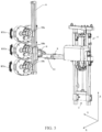
- At least one, preferably each, of the stripping heads 5 has another degree of freedom of rotation RYa, RYb, RYc, relative to the rail 6, around the working axis T, as best shown in Fig. 5 .
- Their assembly thus allowing a degree of rotational freedom RYa, RYb, RYc and therefore to modify the orientation of each of the stripping heads 5a-c independently of each of the others in order to modify the height and/or density of the stripping.
- the rail 6, carrying the stripping heads further comprises at least one articulation around an axis substantially parallel to the horizontal axis X. This makes it possible to make the rail 6 conform to an interrupted line. Depending on the number of joints, the rail 6 can adopt a V, L, C, M, W or other shape, in order to closely match the shape of the tree or bush to be defoliated.
- the rail 6 is carried by a structure 3.
- This structure 3 comprises a fixed lower end 7 or fixed part 7 and a movable upper end or movable part or chassis 2.
- the structure 3 is capable of being fixed at its fixed lower end 7 to a means of transport (not shown), to transport it along the first horizontal axis X.
- This is the advance axis of the movable means of transport, which is substantially parallel to a row of plants or the like to be defoliated.
- the means of transport may be an agricultural vehicle, such as a tractor or a trailer pulled by a tractor or any other equivalent means.
- the structure 3 is transported by the mobile transport vehicle and itself supports the rail 6, integral with the mobile upper end 2 or a mobile part or chassis thereof.
- the structure 3 is deformable by means of one or more links. This makes it possible to shift the position, in a single movement, of the rail 6 and of all the stripping heads 5a-c carried by the latter.
- the actual architecture of this structure 3 can be arbitrary.
- the following description illustrates a possible example of structure 3.
- the structure 3 can be extended or retracted vertically like an arm. By anatomical analogy, its fixed lower end 7 is the one closest to the transport vehicle, while the movable upper end 2 is the one furthest from the transport vehicle. In order to be able to bring the rail 6 and the stripping heads 5a-c that it carries close to a row of vegetation, and to be able to adapt to a row of bushes such as vines or currant bushes, etc.
- a first adjustment means is constituted by a first connection capable of generating a vertical translation movement PZ1. This connection is located between a lower end 7 secured to the transport vehicle and the movable upper part 2 of the structure 3. It allows a translation movement substantially along a vertical axis Z.
- This vertical axis Z is perpendicular to the axis X of movement on the ground and to the Y axis, (therefore to the XY plane) and is perpendicular to the first X axis.
- a beam 8 forming a means of supporting the rail can be driven relative to a lower end 7 with a translational movement parallel to the Z axis, the beam(s) carrying the rail 6, stripping heads 5, a variable inclination means 9, and a sliding connection 11 associated with the movable upper end 2 of the structure 3.
- a third adjustment means is constituted by a third connection capable of generating a translational movement PY, see in particular the fig.
- the beam 8 is horizontal and comprises a sliding connection 11 which can extend substantially parallel to the beam 8.
- the sliding connection 11 is movable with a translation along the second axis Y and varies the spacing of the rail(s) 6 as well as the parts that it supports relative to the structure 3.
- a fourth optional adjustment means consists of a fourth link allowing a degree of freedom allowing rotation RX around an axis substantially parallel to the first axis Z.
- a variable tilt means 9 see in particular the Fig. 5 , implements the fourth connection ensuring a degree of rotational freedom RX, allowing a certain degree of tilting about an axis substantially parallel to the first axis X, of the parts supported by the rail 6, relative to the structure 3.
- the fourth connection allowing a degree of rotational freedom RX comprises abutting flanges, capable of being rotated relative to each other and of being locked together according to variable mutual orientations. As illustrated in Fig.
- the fourth connection comprises two circular flanges facing each other, carrying holes arranged on the same circumference making it possible to define and maintain a given orientation by means of at least one through screw securing the two flanges together, or by means of a variable screw drive or by manual intervention.
- a second adjustment means is constituted by a second connection capable of generating a translational movement PZ2 substantially along a second axis Z2.
- This axis Z2, which is the axis of the rail 6, is generally perpendicular to the axis X. Due to its ability to tilt due to the degree of freedom of rotation RX, its orientation can vary in a plane YZ perpendicular to X. Its default position, as shown in the figures, is substantially vertical, i.e.
- the second adjustment means can vary the position of the rail 6 as well as the parts carried on it relative to the structure 3 in the direction PZ2 along the axis Z2, in both directions. It can thus adjust the position of all the stripping heads 5a-c with a coordinated or differentiated movement.
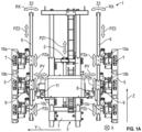
- FIGURE 1 illustrates a configuration of structure 3 at the lowest position of the PZ1 degree of freedom, with the PY degree of freedom producing its most compact position, and the fourth link allowing the RX rotation adjusted so that the Z2 axis of the rail 6, coincides with the Z axis.
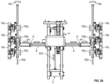
- FIGURE 2 illustrates another configuration of the structure 3 at the highest position of the movement PZ1, with the degree of freedom PY producing its most extended position, and the fourth link allowing the rotation RX again adjusted so that the axis Z2 of the rail 6, coincides with the axis Z.
- each of the links can be driven to adapt a position according to one of the degrees of freedom independently of the others. Due to the way in which the structure 3 is organized, a movement of any one of the links influences the position of all the components supported by the rail 6. All the links have been described above as mechanical. The person skilled in the art knows how to implement components making it possible to produce a link capable of generating a translational movement or a link capable of generating a rotational movement.
- the first connection capable of generating a translational movement PZ1 and the second sliding connection PY are motorized, preferably by an actuator.
- the stripper 1 may further comprise a second rail, substantially symmetrical to the first rail relative to the structure 3.
- a stripper 1 comprises at least one stripping head 5 carried by the structure 3, to perform stripping on one side, for example to the left on the fig. 1 And 2 , and has at least one head stripping carried by the same structure 3, to perform stripping on the other side, or on the right in the figures.
- Such a feature advantageously allows, in a single pass, the transport vehicle to perform stripping simultaneously on two neighboring rows of vegetation.
- the third connection generates an essentially horizontal translational movement PY of each rail 6 relative to the structure 3 makes it possible to adapt the stripper 1 to the distance between the two rows of vegetation.
- the two rails can be completely independent.
- the first and second rails connected to the common structure 3 by beams 8 are similar and all have the same translational and rotational movements. In this case, there is only one chassis 2.
- a horizontal beam 8 comprises two sliding connections 11, one at each of its ends.
- the structure 3 comprises a connection capable of generating a translational movement PY of its rail extending along the second axis Y from the movable part or chassis 2 of the structure and directed to one side, for example the left side
- the second structure comprises another articulation capable of generating a translational movement PY of its rail along the second axis Y from the movable part or chassis 2 of the structure in the opposite direction, i.e. the right side.
- the stripping heads 5a-c must be supplied with energy to enable them to perform their stripping function.
- the stripper 1 further comprises a pneumatic supply (not shown). This pneumatic supply is suitable for the production of compressed air.
- This pneumatic supply can be mounted on the structure 3, carried by the transport vehicle or by a trailer coupled to the transport vehicle.
- this pneumatic supply draws its energy from a power take-off of the transport vehicle.
- the capacity of the pneumatic supply is configurable according to the desired stripping power and the number of stripping heads. Any number of stripping heads can be used. To strip vegetation of limited height, a single stripping head 5 may be sufficient.
- the drawings show a configuration with three stripping heads 5a-c. Ten or more stripping heads 5 can be used depending on the height to be stripped and the desired stripping density. The length of the rail 6 is adapted accordingly.
Landscapes
- Life Sciences & Earth Sciences (AREA)
- Environmental Sciences (AREA)
- Botany (AREA)
- Biodiversity & Conservation Biology (AREA)
- Ecology (AREA)
- Forests & Forestry (AREA)
- Engineering & Computer Science (AREA)
- Wood Science & Technology (AREA)
- Soil Working Implements (AREA)
- Guiding Agricultural Machines (AREA)
- Harvesting Machines For Specific Crops (AREA)
- Agricultural Machines (AREA)
Claims (10)
- Landwirtschaftliche Entlaubungsmaschine (1), die die Freiheitsgrade aufweist, die es ihr erlauben, sich an alle Arten der Pflanzengattungen, an denen die Entlaubung vorgenommen werden soll, anzupassen, dank ihrer Fähigkeit, sich an die besondere Form der Pflanzen anzupassen, umfassend mindestens eine erste Struktur (3), die geeignet ist, an die herkömmlichen Fördermittel in einer horizontalen Verlagerungsrichtung entlang einer Achse (X) im Wesentlichen parallel zur Ebene XY des Bodens angepasst zu werden, wobei diese Entlaubungsmaschine ferner umfasst:- einen festen Teil (7), der geeignet ist, mit einem unteren Ende desselben mit den Fördermitteln verbunden zu werden,- einen beweglichen Teil oder Rahmen (2), der vertikal in Bezug zum festen Teil (7) verlagerbar ist,- mindestens eine Schiene (6), die mindestens zwei Entlaubungsköpfe (5) trägt, die von Haltemitteln (8) getragen werden, die von dem beweglichen Teil oder Rahmen (2) getragen werden, wobei die mindestens eine Schiene von der Struktur beabstandet und im Allgemeinen zu dieser parallel ist,- eine erste Verbindung, die geeignet ist, eine vertikale Translationsbewegung PZ1 zu erzeugen, die erhalten wird, wobei der obere Teil der Struktur (3) in Bezug zum festen unteren Teil (7) der Struktur (3) entlang einer im Allgemeinen vertikalen Achse senkrecht auf die horizontale Verlagerungsrichtung (X) gleitet,- eine zweite Verbindung, die geeignet ist, eine vertikale Translationsbewegung PZ2 der mindestens einen Schiene (6) in Bezug zu den Haltemitteln (8), die von dem beweglichen Teil oder Rahmen (2) getragen werden, entlang einer zweiten Achse Z2 im Allgemeinen senkrecht auf die horizontale Verlagerungsrichtung (X) zu erzeugen,- eine dritte Verbindung, die geeignet ist, eine Beabstandung zwischen der mindestens einen Schiene und der Struktur (3) zu variieren, wobei eine Translationsbewegung PY der mindestens einen Schiene in Bezug zu der Struktur entlang einer Richtung im Allgemeinen orthogonal zu der Richtung einer Vertikalachse und entlang einer Achse der Haltemittel (8) erzeugt wird,- eine vierte Verbindung, die geeignet ist, eine Rotationsbewegung RX der mindestens einen Schiene (6) um eine Achse im Wesentlichen senkrecht auf die horizontale Verlagerungsrichtung (X) zu erzeugen, wobei diese Entlaubungsmaschine gekennzeichnet ist durch:- eine Druckluftquelle, die geeignet ist, Druckluft zu erzeugen, die dazu bestimmt ist, durch die Entlaubungsköpfe (5) ausgeblasen zu werden, und ein Rohrsystem, das die Druckluftquelle mit jedem der Entlaubungsköpfe verbindet, um an sie die auszublasende Druckluft zu liefern, und- wobei die Achsen der vier Verbindungen und die Verlagerungsrichtung der Fördermittel zueinander und in Bezug zu ihrer horizontalen Verlagerungsrichtung (X) parallel oder orthogonal sind.
- Landwirtschaftliche Entlaubungsmaschine (1) nach Anspruch 1, die eine zweite Schiene (6) umfasst, die es ermöglicht, die Entlaubung auf der einen und der anderen Seite der Struktur (3) in einer horizontalen Verlagerungsrichtung entlang einer Achse (X) im Wesentlichen parallel zum Boden durchzuführen, wobei die zweite Schiene (6), die zur ersten symmetrisch ist, mindestens einen Entlaubungskopf (5) trägt, der von Haltemitteln (8) getragen wird, die von dem beweglichen Teil oder Rahmen (2) getragen werden, und wobei die zwei Schienen (6) von der Struktur (3) beabstandet und im Allgemeinen zu dieser parallel sind.
- Entlaubungsmaschine (1) nach Anspruch 1 oder 2, bei der die erste Struktur und eine zweite Struktur einen einzigen Zusammenbau bilden.
- Entlaubungsmaschine (1) nach einem der vorhergehenden Ansprüche, bei der die mindestens zwei Entlaubungsköpfe gleitend auf der Schiene und durch eine Translationsbewegung entlang der Schiene(n) beweglich montiert sind, wobei ihre Arbeitsachsen im Wesentlichen auf eine Achse Z2 der Schiene senkrecht sind.
- Entlaubungsmaschine (1) nach einem der vorhergehenden Ansprüche, bei der mindestens einer der Entlaubungsköpfe (5) einen Freiheitsgrad hat, der eine Translationsbewegung (PZa, PZb, PZc) des(r)selben entlang der Schiene(n) (6) unabhängig von jedem der anderen Entlaubungsköpfe erlaubt.
- Entlaubungsmaschine (1) nach einem der vorhergehenden Ansprüche, bei der mindestens einer der Entlaubungsköpfe (5) ferner einen Freiheitsgrad hat, der eine Rotationsbewegung (RYa, RYb, RYc) in Bezug zu einer Arbeitsachse (7) erlaubt.
- Entlaubungsmaschine (1) nach einem der vorhergehenden Ansprüche, bei der die Schiene (6), die die Entlaubungsköpfe (5) trägt, ferner mindestens ein Gelenk um eine Achse im Wesentlichen parallel zu der horizontalen Verlagerungsrichtung (X) umfasst, das es ermöglicht, die Schiene(n) an eine gebogene Linie oder eine unterbrochene Linie anzupassen.
- Entlaubungsmaschine (1) nach einem der vorhergehenden Ansprüche, bei der die erste Verbindung, die geeignet ist, eine vertikale Translationsbewegung PZ1 zu erzeugen, die erhalten wird, wobei der obere Teil der Struktur (3) in Bezug zum unteren festen Teil (7) derselben gleitet, und die dritte Verbindung, die geeignet ist, eine Translationsbewegung PY der einen oder der zwei Schienen (6) in Bezug zu der Struktur (3) zu erzeugen, motorbetrieben sind.
- Entlaubungsmaschine (1) nach einem der vorhergehenden Ansprüche, bei der die erste Verbindung, die geeignet ist, eine vertikale Translationsbewegung PZ1 zu erzeugen, und die dritte Verbindung, die geeignet ist, eine Translationsbewegung PY der Schiene in Bezug zu der Struktur zu erzeugen, durch einen Aktuator eingesetzt werden.
- Entlaubungsmaschine (1) nach einem der vorhergehenden Ansprüche, umfassend ein einziges Haltemittel, das in der Struktur (3) besteht, die jede der Schienen (6) trägt, und umfassend zwei Gleitverbindungen (11), die jeweils geeignet sind, eine Beabstandung zwischen jeder der Schienen (6) und der Struktur (3) zu variieren.
Applications Claiming Priority (1)
| Application Number | Priority Date | Filing Date | Title |
|---|---|---|---|
| FR2006587A FR3111764B1 (fr) | 2020-06-24 | 2020-06-24 | Effeuilleuse |
Publications (2)
| Publication Number | Publication Date |
|---|---|
| EP3928613A1 EP3928613A1 (de) | 2021-12-29 |
| EP3928613B1 true EP3928613B1 (de) | 2024-11-27 |
Family
ID=73497841
Family Applications (1)
| Application Number | Title | Priority Date | Filing Date |
|---|---|---|---|
| EP21175327.2A Active EP3928613B1 (de) | 2020-06-24 | 2021-05-21 | Entblätterungsmaschine |
Country Status (6)
| Country | Link |
|---|---|
| US (1) | US11666009B2 (de) |
| EP (1) | EP3928613B1 (de) |
| CN (1) | CN113826501B (de) |
| AU (1) | AU2021203251B2 (de) |
| CA (1) | CA3120319A1 (de) |
| FR (1) | FR3111764B1 (de) |
Families Citing this family (4)
| Publication number | Priority date | Publication date | Assignee | Title |
|---|---|---|---|---|
| USD984488S1 (en) * | 2021-02-15 | 2023-04-25 | Etablissements Collard | Oval-shaped pneumatic stripping head for a leaf removal machine |
| FR3142320B1 (fr) * | 2022-11-29 | 2024-12-13 | Naotec | Dispositif de coupe pour la végétation |
| CN119302139A (zh) * | 2024-11-15 | 2025-01-14 | 农业农村部南京农业机械化研究所 | 一种脉冲气吹式摘叶结构以及装置 |
| CN119498128B (zh) * | 2024-12-17 | 2025-10-17 | 江苏省农业科学院 | 一种温室轨道式吊蔓作物打叶机器人 |
Citations (1)
| Publication number | Priority date | Publication date | Assignee | Title |
|---|---|---|---|---|
| US9247691B2 (en) * | 2012-06-27 | 2016-02-02 | Sunview Vineyards Of California | Device for pruning plant growth |
Family Cites Families (15)
| Publication number | Priority date | Publication date | Assignee | Title |
|---|---|---|---|---|
| FR2289112A1 (fr) * | 1974-11-04 | 1976-05-28 | Gallay Maurice | Effeuilleuse mecanique a air comprime |
| US4027733A (en) * | 1975-08-28 | 1977-06-07 | Eisenhardt Fred W | Weed pulling machine |
| US5544444A (en) * | 1994-12-22 | 1996-08-13 | Oldridge; Tommy L. | Single curtain wine and juice grape vine pruner |
| DE19717198A1 (de) * | 1997-04-24 | 1998-10-29 | Rinklin Willi | Rebenbearbeitungseinrichtung |
| ES2196517T3 (es) * | 1997-08-21 | 2003-12-16 | Ind Et Nature De Navarre I2N S | Dispositivo para el deshojado de viñedos. |
| US6634162B1 (en) * | 2002-06-17 | 2003-10-21 | Matt Andros | Simultaneous processing of multiple rows of plants, especially trellised rows |
| DE102007051989B4 (de) * | 2007-10-31 | 2011-04-07 | Willy Rinklin | Rebenvorschneider |
| FR2965145B1 (fr) * | 2010-09-24 | 2012-10-05 | Pellenc Sa | Dispositif de contournement automatique des piquets de palissage de haies fruitieres, et machines agricoles en faisant application |
| US9049820B2 (en) * | 2013-03-15 | 2015-06-09 | Skipper Grassing Inc. | Rotary plant hedger |
| ITTO20130556A1 (it) * | 2013-07-03 | 2015-01-04 | Olmi S R L | Testa defogliatrice pneumatica. |
| ES2871425T3 (es) * | 2014-07-03 | 2021-10-28 | B M V S R L | Dispositivo de selección para poda selectiva instalable en podadoras |
| CN104521678B (zh) * | 2015-01-12 | 2017-04-05 | 中国农业大学 | 一种葡萄果实外部枝叶修剪机 |
| FR3069131B1 (fr) | 2017-07-21 | 2019-12-20 | Etablissements Collard | Systeme d’effeuillage pneumatique et machine agricole equipee d’un tel systeme |
| CN207911560U (zh) * | 2017-08-09 | 2018-09-28 | 高拉德公司 | 用于藤蔓作物、特别是葡萄树的预修剪机 |
| CN207766966U (zh) * | 2018-01-23 | 2018-08-28 | 华中农业大学 | 一种整行齐切式果树修剪机 |
-
2020
- 2020-06-24 FR FR2006587A patent/FR3111764B1/fr active Active
-
2021
- 2021-05-20 AU AU2021203251A patent/AU2021203251B2/en active Active
- 2021-05-21 EP EP21175327.2A patent/EP3928613B1/de active Active
- 2021-05-27 US US17/332,195 patent/US11666009B2/en active Active
- 2021-06-01 CA CA3120319A patent/CA3120319A1/en active Pending
- 2021-06-23 CN CN202110697237.XA patent/CN113826501B/zh active Active
Patent Citations (1)
| Publication number | Priority date | Publication date | Assignee | Title |
|---|---|---|---|---|
| US9247691B2 (en) * | 2012-06-27 | 2016-02-02 | Sunview Vineyards Of California | Device for pruning plant growth |
Also Published As
| Publication number | Publication date |
|---|---|
| CA3120319A1 (en) | 2021-12-24 |
| US11666009B2 (en) | 2023-06-06 |
| AU2021203251B2 (en) | 2023-01-19 |
| CN113826501A (zh) | 2021-12-24 |
| CN113826501B (zh) | 2025-08-19 |
| AU2021203251A1 (en) | 2022-01-20 |
| FR3111764B1 (fr) | 2022-09-02 |
| US20210400886A1 (en) | 2021-12-30 |
| FR3111764A1 (fr) | 2021-12-31 |
| EP3928613A1 (de) | 2021-12-29 |
Similar Documents
| Publication | Publication Date | Title |
|---|---|---|
| EP3928613A1 (de) | Entblätterungsmaschine | |
| EP0312126B2 (de) | Schneidapparat zur Verwendung in der Landwirtschaft, dem Weinbau und der Baumgärtnerei | |
| EP1366650A1 (de) | Landwirschaftliche Maschine mit einer Vorrichtung für die Transportstellung | |
| EP2720528B1 (de) | Maschine zum automatischen ziehen von abgeschnittenen weinreben | |
| EP2196080B1 (de) | Erntemaschine für kleine Früchte im Obstanbau | |
| EP2820931A1 (de) | Bodenbearbeitungsmaschine mit einer verbesserten Vorrichtung zum Einstellen der Arbeitstiefe | |
| EP4062752B1 (de) | Modul zur complantation von rebenpflanzen, vorrichtung zur complantation, die dieses modul umfasst | |
| FR2543787A1 (fr) | Chassis porteur combine avec une machine agricole telle qu'une machine a travailler le sol | |
| FR2979519A1 (fr) | Procede et machine de travail du sol entre des plantations | |
| EP1201116A1 (de) | Schneidevorrichtung, insbesondere zum Entfernen von Geiztrieben | |
| FR3167833A1 (fr) | Extracteur de feuilles pour un rang végétal et notamment un rang de vigne | |
| FR2867943A1 (fr) | Disque de travail du sol et machine de traitement du sol equipee de tels disques | |
| EP2183956B1 (de) | Heuwerbungsmaschine | |
| EP0190777B1 (de) | Roder | |
| EP3375271B1 (de) | Landwirtschaftliche maschine zur bodenbearbeitung, die mindestens zwei wechselseitig versetzte scheibenreihen umfasst, deren position in vorwärtsrichtung verstellbar ist | |
| EP0611237A1 (de) | Bodenbearbeitungsmaschine, insbesondere Scheibenegge, mit reduzierter Transportbreite, deren Bodenbearbeitungswerkzeugstellung verstellbar ist | |
| FR3069748B1 (fr) | Outil de travail du sol entraine et dispositif de travail de la terre equipe d'au moins un tel outil de travail du sol | |
| EP1463402A1 (de) | Mehrzweckmaschine zur beschränkung des pflanzenwachstums | |
| FR3103350A1 (fr) | Dispositif d'epamprage de plants palisses, notamment des plants de vigne | |
| FR2730123A1 (fr) | Appareil pour ameublir le sol en presence d'un paillis de canne a sucre | |
| FR2770740A1 (fr) | Dechausseuse agricole rotative | |
| FR2730124A1 (fr) | Appareil pour ameublir le sol en presence d'un paillis de canne a sucre. | |
| FR2843274A1 (fr) | Ecrouteuse | |
| FR2855367A1 (fr) | Machine d'effeuillage a tete reversible | |
| BE620546A (de) |
Legal Events
| Date | Code | Title | Description |
|---|---|---|---|
| PUAI | Public reference made under article 153(3) epc to a published international application that has entered the european phase |
Free format text: ORIGINAL CODE: 0009012 |
|
| STAA | Information on the status of an ep patent application or granted ep patent |
Free format text: STATUS: THE APPLICATION HAS BEEN PUBLISHED |
|
| AK | Designated contracting states |
Kind code of ref document: A1 Designated state(s): AL AT BE BG CH CY CZ DE DK EE ES FI FR GB GR HR HU IE IS IT LI LT LU LV MC MK MT NL NO PL PT RO RS SE SI SK SM TR |
|
| B565 | Issuance of search results under rule 164(2) epc |
Effective date: 20211110 |
|
| STAA | Information on the status of an ep patent application or granted ep patent |
Free format text: STATUS: REQUEST FOR EXAMINATION WAS MADE |
|
| 17P | Request for examination filed |
Effective date: 20220211 |
|
| RBV | Designated contracting states (corrected) |
Designated state(s): AL AT BE BG CH CY CZ DE DK EE ES FI FR GB GR HR HU IE IS IT LI LT LU LV MC MK MT NL NO PL PT RO RS SE SI SK SM TR |
|
| STAA | Information on the status of an ep patent application or granted ep patent |
Free format text: STATUS: EXAMINATION IS IN PROGRESS |
|
| 17Q | First examination report despatched |
Effective date: 20220704 |
|
| RAP3 | Party data changed (applicant data changed or rights of an application transferred) |
Owner name: COLLARD |
|
| P01 | Opt-out of the competence of the unified patent court (upc) registered |
Effective date: 20230704 |
|
| GRAP | Despatch of communication of intention to grant a patent |
Free format text: ORIGINAL CODE: EPIDOSNIGR1 |
|
| STAA | Information on the status of an ep patent application or granted ep patent |
Free format text: STATUS: GRANT OF PATENT IS INTENDED |
|
| INTG | Intention to grant announced |
Effective date: 20240619 |
|
| GRAS | Grant fee paid |
Free format text: ORIGINAL CODE: EPIDOSNIGR3 |
|
| GRAA | (expected) grant |
Free format text: ORIGINAL CODE: 0009210 |
|
| STAA | Information on the status of an ep patent application or granted ep patent |
Free format text: STATUS: THE PATENT HAS BEEN GRANTED |
|
| AK | Designated contracting states |
Kind code of ref document: B1 Designated state(s): AL AT BE BG CH CY CZ DE DK EE ES FI FR GB GR HR HU IE IS IT LI LT LU LV MC MK MT NL NO PL PT RO RS SE SI SK SM TR |
|
| REG | Reference to a national code |
Ref country code: GB Ref legal event code: FG4D Free format text: NOT ENGLISH |
|
| REG | Reference to a national code |
Ref country code: CH Ref legal event code: EP |
|
| REG | Reference to a national code |
Ref country code: DE Ref legal event code: R096 Ref document number: 602021022300 Country of ref document: DE |
|
| REG | Reference to a national code |
Ref country code: IE Ref legal event code: FG4D Free format text: LANGUAGE OF EP DOCUMENT: FRENCH |
|
| REG | Reference to a national code |
Ref country code: LT Ref legal event code: MG9D |
|
| REG | Reference to a national code |
Ref country code: NL Ref legal event code: MP Effective date: 20241127 |
|
| PG25 | Lapsed in a contracting state [announced via postgrant information from national office to epo] |
Ref country code: IS Free format text: LAPSE BECAUSE OF FAILURE TO SUBMIT A TRANSLATION OF THE DESCRIPTION OR TO PAY THE FEE WITHIN THE PRESCRIBED TIME-LIMIT Effective date: 20250327 Ref country code: PT Free format text: LAPSE BECAUSE OF FAILURE TO SUBMIT A TRANSLATION OF THE DESCRIPTION OR TO PAY THE FEE WITHIN THE PRESCRIBED TIME-LIMIT Effective date: 20250327 Ref country code: HR Free format text: LAPSE BECAUSE OF FAILURE TO SUBMIT A TRANSLATION OF THE DESCRIPTION OR TO PAY THE FEE WITHIN THE PRESCRIBED TIME-LIMIT Effective date: 20241127 |
|
| PG25 | Lapsed in a contracting state [announced via postgrant information from national office to epo] |
Ref country code: FI Free format text: LAPSE BECAUSE OF FAILURE TO SUBMIT A TRANSLATION OF THE DESCRIPTION OR TO PAY THE FEE WITHIN THE PRESCRIBED TIME-LIMIT Effective date: 20241127 Ref country code: NL Free format text: LAPSE BECAUSE OF FAILURE TO SUBMIT A TRANSLATION OF THE DESCRIPTION OR TO PAY THE FEE WITHIN THE PRESCRIBED TIME-LIMIT Effective date: 20241127 |
|
| PG25 | Lapsed in a contracting state [announced via postgrant information from national office to epo] |
Ref country code: BG Free format text: LAPSE BECAUSE OF FAILURE TO SUBMIT A TRANSLATION OF THE DESCRIPTION OR TO PAY THE FEE WITHIN THE PRESCRIBED TIME-LIMIT Effective date: 20241127 |
|
| PG25 | Lapsed in a contracting state [announced via postgrant information from national office to epo] |
Ref country code: ES Free format text: LAPSE BECAUSE OF FAILURE TO SUBMIT A TRANSLATION OF THE DESCRIPTION OR TO PAY THE FEE WITHIN THE PRESCRIBED TIME-LIMIT Effective date: 20241127 |
|
| PG25 | Lapsed in a contracting state [announced via postgrant information from national office to epo] |
Ref country code: NO Free format text: LAPSE BECAUSE OF FAILURE TO SUBMIT A TRANSLATION OF THE DESCRIPTION OR TO PAY THE FEE WITHIN THE PRESCRIBED TIME-LIMIT Effective date: 20250227 |
|
| PG25 | Lapsed in a contracting state [announced via postgrant information from national office to epo] |
Ref country code: LV Free format text: LAPSE BECAUSE OF FAILURE TO SUBMIT A TRANSLATION OF THE DESCRIPTION OR TO PAY THE FEE WITHIN THE PRESCRIBED TIME-LIMIT Effective date: 20241127 Ref country code: GR Free format text: LAPSE BECAUSE OF FAILURE TO SUBMIT A TRANSLATION OF THE DESCRIPTION OR TO PAY THE FEE WITHIN THE PRESCRIBED TIME-LIMIT Effective date: 20250228 |
|
| PG25 | Lapsed in a contracting state [announced via postgrant information from national office to epo] |
Ref country code: PL Free format text: LAPSE BECAUSE OF FAILURE TO SUBMIT A TRANSLATION OF THE DESCRIPTION OR TO PAY THE FEE WITHIN THE PRESCRIBED TIME-LIMIT Effective date: 20241127 |
|
| PGFP | Annual fee paid to national office [announced via postgrant information from national office to epo] |
Ref country code: IT Payment date: 20250131 Year of fee payment: 5 |
|
| PG25 | Lapsed in a contracting state [announced via postgrant information from national office to epo] |
Ref country code: RS Free format text: LAPSE BECAUSE OF FAILURE TO SUBMIT A TRANSLATION OF THE DESCRIPTION OR TO PAY THE FEE WITHIN THE PRESCRIBED TIME-LIMIT Effective date: 20250227 |
|
| PG25 | Lapsed in a contracting state [announced via postgrant information from national office to epo] |
Ref country code: SM Free format text: LAPSE BECAUSE OF FAILURE TO SUBMIT A TRANSLATION OF THE DESCRIPTION OR TO PAY THE FEE WITHIN THE PRESCRIBED TIME-LIMIT Effective date: 20241127 |
|
| PGFP | Annual fee paid to national office [announced via postgrant information from national office to epo] |
Ref country code: DE Payment date: 20250130 Year of fee payment: 5 |
|
| PG25 | Lapsed in a contracting state [announced via postgrant information from national office to epo] |
Ref country code: DK Free format text: LAPSE BECAUSE OF FAILURE TO SUBMIT A TRANSLATION OF THE DESCRIPTION OR TO PAY THE FEE WITHIN THE PRESCRIBED TIME-LIMIT Effective date: 20241127 |
|
| PG25 | Lapsed in a contracting state [announced via postgrant information from national office to epo] |
Ref country code: EE Free format text: LAPSE BECAUSE OF FAILURE TO SUBMIT A TRANSLATION OF THE DESCRIPTION OR TO PAY THE FEE WITHIN THE PRESCRIBED TIME-LIMIT Effective date: 20241127 |
|
| PG25 | Lapsed in a contracting state [announced via postgrant information from national office to epo] |
Ref country code: RO Free format text: LAPSE BECAUSE OF FAILURE TO SUBMIT A TRANSLATION OF THE DESCRIPTION OR TO PAY THE FEE WITHIN THE PRESCRIBED TIME-LIMIT Effective date: 20241127 |
|
| PGFP | Annual fee paid to national office [announced via postgrant information from national office to epo] |
Ref country code: AT Payment date: 20250721 Year of fee payment: 5 |
|
| PG25 | Lapsed in a contracting state [announced via postgrant information from national office to epo] |
Ref country code: SK Free format text: LAPSE BECAUSE OF FAILURE TO SUBMIT A TRANSLATION OF THE DESCRIPTION OR TO PAY THE FEE WITHIN THE PRESCRIBED TIME-LIMIT Effective date: 20241127 |
|
| PG25 | Lapsed in a contracting state [announced via postgrant information from national office to epo] |
Ref country code: CZ Free format text: LAPSE BECAUSE OF FAILURE TO SUBMIT A TRANSLATION OF THE DESCRIPTION OR TO PAY THE FEE WITHIN THE PRESCRIBED TIME-LIMIT Effective date: 20241127 |
|
| REG | Reference to a national code |
Ref country code: DE Ref legal event code: R097 Ref document number: 602021022300 Country of ref document: DE |
|
| PG25 | Lapsed in a contracting state [announced via postgrant information from national office to epo] |
Ref country code: SE Free format text: LAPSE BECAUSE OF FAILURE TO SUBMIT A TRANSLATION OF THE DESCRIPTION OR TO PAY THE FEE WITHIN THE PRESCRIBED TIME-LIMIT Effective date: 20241127 |
|
| PLBE | No opposition filed within time limit |
Free format text: ORIGINAL CODE: 0009261 |
|
| STAA | Information on the status of an ep patent application or granted ep patent |
Free format text: STATUS: NO OPPOSITION FILED WITHIN TIME LIMIT |
|
| REG | Reference to a national code |
Ref country code: CH Ref legal event code: L10 Free format text: ST27 STATUS EVENT CODE: U-0-0-L10-L00 (AS PROVIDED BY THE NATIONAL OFFICE) Effective date: 20251008 |
|
| 26N | No opposition filed |
Effective date: 20250828 |
|
| REG | Reference to a national code |
Ref country code: CH Ref legal event code: H13 Free format text: ST27 STATUS EVENT CODE: U-0-0-H10-H13 (AS PROVIDED BY THE NATIONAL OFFICE) Effective date: 20251223 |
|
| PG25 | Lapsed in a contracting state [announced via postgrant information from national office to epo] |
Ref country code: LU Free format text: LAPSE BECAUSE OF NON-PAYMENT OF DUE FEES Effective date: 20250521 |
|
| PG25 | Lapsed in a contracting state [announced via postgrant information from national office to epo] |
Ref country code: CH Free format text: LAPSE BECAUSE OF NON-PAYMENT OF DUE FEES Effective date: 20250531 |
|
| GBPC | Gb: european patent ceased through non-payment of renewal fee |
Effective date: 20250521 |
|
| REG | Reference to a national code |
Ref country code: BE Ref legal event code: MM Effective date: 20250531 |
|
| PG25 | Lapsed in a contracting state [announced via postgrant information from national office to epo] |
Ref country code: MC Free format text: LAPSE BECAUSE OF FAILURE TO SUBMIT A TRANSLATION OF THE DESCRIPTION OR TO PAY THE FEE WITHIN THE PRESCRIBED TIME-LIMIT Effective date: 20241127 |
|
| REG | Reference to a national code |
Ref country code: DE Ref legal event code: R082 Ref document number: 602021022300 Country of ref document: DE Ref country code: DE Ref legal event code: R082 Ref document number: 602021022300 Country of ref document: DE Representative=s name: PLASSERAUD IP GMBH, DE |
|
| REG | Reference to a national code |
Ref country code: AT Ref legal event code: UEP Ref document number: 1744760 Country of ref document: AT Kind code of ref document: T Effective date: 20241127 |
|
| PG25 | Lapsed in a contracting state [announced via postgrant information from national office to epo] |
Ref country code: GB Free format text: LAPSE BECAUSE OF NON-PAYMENT OF DUE FEES Effective date: 20250521 |
|
| PG25 | Lapsed in a contracting state [announced via postgrant information from national office to epo] |
Ref country code: IE Free format text: LAPSE BECAUSE OF NON-PAYMENT OF DUE FEES Effective date: 20250521 |
|
| PG25 | Lapsed in a contracting state [announced via postgrant information from national office to epo] |
Ref country code: BE Free format text: LAPSE BECAUSE OF NON-PAYMENT OF DUE FEES Effective date: 20250531 |
|
| REG | Reference to a national code |
Ref country code: DE Ref legal event code: R082 Ref document number: 602021022300 Country of ref document: DE Representative=s name: PLASSERAUD IP GMBH, DE |
|
| PGFP | Annual fee paid to national office [announced via postgrant information from national office to epo] |
Ref country code: FR Payment date: 20260226 Year of fee payment: 6 |