EP3926113B1 - Double-side expansion cabin type mobile nucleic acid detection laboratory - Google Patents
Double-side expansion cabin type mobile nucleic acid detection laboratory Download PDFInfo
- Publication number
- EP3926113B1 EP3926113B1 EP21155667.5A EP21155667A EP3926113B1 EP 3926113 B1 EP3926113 B1 EP 3926113B1 EP 21155667 A EP21155667 A EP 21155667A EP 3926113 B1 EP3926113 B1 EP 3926113B1
- Authority
- EP
- European Patent Office
- Prior art keywords
- cabin
- expansion
- tent
- long support
- base plate
- Prior art date
- Legal status (The legal status is an assumption and is not a legal conclusion. Google has not performed a legal analysis and makes no representation as to the accuracy of the status listed.)
- Active
Links
Images



Classifications
-
- E—FIXED CONSTRUCTIONS
- E04—BUILDING
- E04H—BUILDINGS OR LIKE STRUCTURES FOR PARTICULAR PURPOSES; SWIMMING OR SPLASH BATHS OR POOLS; MASTS; FENCING; TENTS OR CANOPIES, IN GENERAL
- E04H15/00—Tents or canopies, in general
- E04H15/32—Parts, components, construction details, accessories, interior equipment, specially adapted for tents, e.g. guy-line equipment, skirts, thresholds
- E04H15/34—Supporting means, e.g. frames
- E04H15/44—Supporting means, e.g. frames collapsible, e.g. breakdown type
- E04H15/48—Supporting means, e.g. frames collapsible, e.g. breakdown type foldable, i.e. having pivoted or hinged means
- E04H15/50—Supporting means, e.g. frames collapsible, e.g. breakdown type foldable, i.e. having pivoted or hinged means lazy-tongs type
- E04H15/505—Supporting means, e.g. frames collapsible, e.g. breakdown type foldable, i.e. having pivoted or hinged means lazy-tongs type characterised by connecting arches with lazy-tongues
-
- E—FIXED CONSTRUCTIONS
- E04—BUILDING
- E04H—BUILDINGS OR LIKE STRUCTURES FOR PARTICULAR PURPOSES; SWIMMING OR SPLASH BATHS OR POOLS; MASTS; FENCING; TENTS OR CANOPIES, IN GENERAL
- E04H3/00—Buildings or groups of buildings for public or similar purposes; Institutions, e.g. infirmaries or prisons
- E04H3/08—Hospitals, infirmaries, or the like; Schools; Prisons
-
- E—FIXED CONSTRUCTIONS
- E04—BUILDING
- E04B—GENERAL BUILDING CONSTRUCTIONS; WALLS, e.g. PARTITIONS; ROOFS; FLOORS; CEILINGS; INSULATION OR OTHER PROTECTION OF BUILDINGS
- E04B1/00—Constructions in general; Structures which are not restricted either to walls, e.g. partitions, or floors or ceilings or roofs
- E04B1/343—Structures characterised by movable, separable, or collapsible parts, e.g. for transport
- E04B1/344—Structures characterised by movable, separable, or collapsible parts, e.g. for transport with hinged parts
- E04B1/3442—Structures characterised by movable, separable, or collapsible parts, e.g. for transport with hinged parts folding out from a core cell
- E04B1/3444—Structures characterised by movable, separable, or collapsible parts, e.g. for transport with hinged parts folding out from a core cell with only lateral unfolding
-
- E—FIXED CONSTRUCTIONS
- E04—BUILDING
- E04B—GENERAL BUILDING CONSTRUCTIONS; WALLS, e.g. PARTITIONS; ROOFS; FLOORS; CEILINGS; INSULATION OR OTHER PROTECTION OF BUILDINGS
- E04B1/00—Constructions in general; Structures which are not restricted either to walls, e.g. partitions, or floors or ceilings or roofs
- E04B1/343—Structures characterised by movable, separable, or collapsible parts, e.g. for transport
- E04B1/344—Structures characterised by movable, separable, or collapsible parts, e.g. for transport with hinged parts
- E04B1/3445—Structures characterised by movable, separable, or collapsible parts, e.g. for transport with hinged parts foldable in a flat stack of parallel panels
-
- E—FIXED CONSTRUCTIONS
- E04—BUILDING
- E04B—GENERAL BUILDING CONSTRUCTIONS; WALLS, e.g. PARTITIONS; ROOFS; FLOORS; CEILINGS; INSULATION OR OTHER PROTECTION OF BUILDINGS
- E04B1/00—Constructions in general; Structures which are not restricted either to walls, e.g. partitions, or floors or ceilings or roofs
- E04B1/343—Structures characterised by movable, separable, or collapsible parts, e.g. for transport
- E04B1/3455—Wheeled arch-type structures
-
- E—FIXED CONSTRUCTIONS
- E04—BUILDING
- E04H—BUILDINGS OR LIKE STRUCTURES FOR PARTICULAR PURPOSES; SWIMMING OR SPLASH BATHS OR POOLS; MASTS; FENCING; TENTS OR CANOPIES, IN GENERAL
- E04H1/00—Buildings or groups of buildings for dwelling or office purposes; General layout, e.g. modular co-ordination or staggered storeys
- E04H1/12—Small buildings or other erections for limited occupation, erected in the open air or arranged in buildings, e.g. kiosks, waiting shelters for bus stops or for filling stations, roofs for railway platforms, watchmen's huts or dressing cubicles
- E04H1/1205—Small buildings erected in the open air
-
- E—FIXED CONSTRUCTIONS
- E04—BUILDING
- E04H—BUILDINGS OR LIKE STRUCTURES FOR PARTICULAR PURPOSES; SWIMMING OR SPLASH BATHS OR POOLS; MASTS; FENCING; TENTS OR CANOPIES, IN GENERAL
- E04H15/00—Tents or canopies, in general
- E04H15/02—Tents combined or specially associated with other devices
-
- E—FIXED CONSTRUCTIONS
- E04—BUILDING
- E04H—BUILDINGS OR LIKE STRUCTURES FOR PARTICULAR PURPOSES; SWIMMING OR SPLASH BATHS OR POOLS; MASTS; FENCING; TENTS OR CANOPIES, IN GENERAL
- E04H15/00—Tents or canopies, in general
- E04H15/32—Parts, components, construction details, accessories, interior equipment, specially adapted for tents, e.g. guy-line equipment, skirts, thresholds
- E04H15/34—Supporting means, e.g. frames
- E04H15/44—Supporting means, e.g. frames collapsible, e.g. breakdown type
- E04H15/48—Supporting means, e.g. frames collapsible, e.g. breakdown type foldable, i.e. having pivoted or hinged means
-
- E—FIXED CONSTRUCTIONS
- E04—BUILDING
- E04H—BUILDINGS OR LIKE STRUCTURES FOR PARTICULAR PURPOSES; SWIMMING OR SPLASH BATHS OR POOLS; MASTS; FENCING; TENTS OR CANOPIES, IN GENERAL
- E04H15/00—Tents or canopies, in general
- E04H15/32—Parts, components, construction details, accessories, interior equipment, specially adapted for tents, e.g. guy-line equipment, skirts, thresholds
- E04H15/34—Supporting means, e.g. frames
- E04H15/44—Supporting means, e.g. frames collapsible, e.g. breakdown type
- E04H15/48—Supporting means, e.g. frames collapsible, e.g. breakdown type foldable, i.e. having pivoted or hinged means
- E04H15/50—Supporting means, e.g. frames collapsible, e.g. breakdown type foldable, i.e. having pivoted or hinged means lazy-tongs type
Definitions
- the present disclosure relates to the technical field of biosafety protection equipment and peripheral supporting facilities thereof, and in particular to a double-side expansion cabin type mobile nucleic acid detection laboratory.
- a portable expandable shelter in the patent application with publication number US2011/132421 A1 , includes an enclosure with one or more movable portions such as a side or end, and further includes a foldable frame configured and arranged for operation in unison with movement of the movable portion of the enclosure.
- This example of the portable expandable shelter also includes a cover that encloses at least a portion of a space defined by the movable portion and the foldable frame.
- the patent application with publication number CN110656790A discloses an expanded intelligent shelter.
- the expanded intelligent shelter solves the problems in the prior art that the interior space is fixed and narrow, and has weak natural illumination.
- the expanded intelligent shelter comprises a shelter main body, wherein the entire surface or part of at least one side of the shelter main body is a movable side plate; after being expanded and flatly laid, the movable side plate is a spreading wing platform; a tent structure matched with the spreading wing platform is stored in the shelter main body; the tent structure is constructed on the spreading wing platform to form a side wing command room; the side wing command room is connected to the inner space of the shelter main body to jointly form a shelter command room; and the movable side plate is provided with a driving mechanism.
- the used space of the interior of the shelter can be effectively expanded, and meanwhile the sufficient natural illumination is ensured; and the interior space of the shelter is spacious and bright, and thus, the command efficiency of the shelter is improved.
- the objective of the present disclosure is to provide a double-side expansion cabin type mobile nucleic acid detection laboratory to solve the problems in the prior art, so as to facilitate the transportation and improve the convenience of vehicle-mounted mobile nucleic acid detection laboratories.
- the present disclosure provides a double-side expansion cabin type mobile nucleic acid detection laboratory, including a fixed cabin, an expansion cabin, and an expansion tent; an equipment room and a central control area are arranged in the fixed cabin; the expansion cabin serves as a preparation room and a PCR room; the expansion tent serves as a core workroom and a liquid preparation room; a buffer room is arranged in each of the fixed cabin, the expansion cabin, and the expansion tent; the expansion cabin and the expansion tent are separately connected to the fixed cabin; both the expansion cabin and the expansion tent can be folded; when completely folded, the expansion cabin and the expansion tent are located in the fixed cabin; when the expansion cabin and the expansion tent are unfolded, both the expansion cabin and the expansion tent communicate with the fixed cabin; the expansion tent is in sealed connection with the fixed cabin.
- the expansion cabin includes a first base plate, a cabin body, and a bracket.
- the first base plate is hinged to the fixed cabin.
- the cabin body is connected to the first base plate.
- the cabin body is made of a flexible material.
- the bracket is connected to the first base plate and the cabin body. When a relative angle between the first base plate and the fixed cabin changes, the bracket can drive the cabin body to move.
- the first base plate is hinged to the bottom of the fixed cabin.
- the bracket includes first connecting rods, a second connecting rod, first long support rods, and a second long support rod.
- One end of the first long support rod is hinged to one end, far away from the fixed cabin, of the first base plate.
- the second long support rod is connected to the top, far away from the fixed cabin, of the cabin body.
- the other end of the first long support rod is hinged to one end of the second long support rod.
- One end of the first connecting rod is hinged to the top of the fixed cabin, and the other end of the first connecting rod is hinged to the first long support rod.
- a hinge point of the first connecting rod and the first long support rod is located between a hinge point of the first long support rod and the second long support rod and a hinge point of the first long support rod and the first base plate.
- the second connecting rod is connected to the top of the cabin body. One end of the second connecting rod is hinged to the second long support rod.
- a hinge point of the second connecting rod and the second long support rod is located between a hinge point of the second long support rod and the first long support rod and a hinge point of the second long support rod and the cabin body.
- both the second long support rod and the second connecting rod are U-shaped rods.
- the two opposite ends of the second long support rod are respectively connected to the two first long support rods.
- the two opposite ends of the second connecting rod are respectively connected to the two opposite ends of the second long support rod.
- the bottoms of the second long support rod and the second connecting rod are separately connected to the cabin body.
- the expansion tent includes a second base plate, an inner tent, an outer tent, and a telescopic skeleton.
- the second base plate is hinged to the fixed cabin.
- One end of the telescopic skeleton is connected to the fixed cabin.
- the inner tent is connected to the telescopic skeleton.
- the outer tent is arranged outside the telescopic skeleton.
- the inner tent is in sealed connection with the fixed cabin.
- the telescopic skeleton can stretch and retract.
- the telescopic skeleton can drive the inner tent to move in a direction far away from the fixed cabin and be tiled to the second base plate.
- the outer tent is detachably connected to the inner tent. Both the inner tent and the outer tent are made of a flexible material.
- the expansion tent further includes a support rail.
- the support rail which is used for supporting the second base plate, is arranged at the bottom of the fixed cabin in a sliding manner.
- the second base plate is of a foldable structure.
- the second base plate can be pressed against the support rail.
- the second base plate includes two plate bodies, where one end of one of the plate bodies is hinged to the fixed cabin, and the opposite end of the plate body is hinged to the other plate body.
- the telescopic skeleton includes a plurality of sliding frames.
- the plurality of the sliding frames is connected through rhombus-shaped telescopic frames.
- the inner tent is arranged inside the sliding frames. Reciprocating movement of the sliding frames along the second base plate can drive the inner tent to fold or unfold.
- pulley wheels are arranged at the bottoms of the sliding frames.
- a slide rail that is adapted to the pulley wheels is arranged on the second base plate.
- the pulley wheels are arranged on the slide rail in a sliding manner.
- the expansion cabin and the expansion tent are respectively arranged on two opposite sides of the fixed cabin.
- the double-side expansion cabin type mobile nucleic acid detection laboratory of the present disclosure includes the fixed cabin, the expansion cabin, and the expansion tent.
- the expansion cabin and the expansion tent are separately connected to the fixed cabin. Both the expansion cabin and the expansion tent can be folded. When completely folded, the expansion cabin and the expansion tent are located in the fixed cabin. When the expansion cabin and the expansion tent are unfolded, both the expansion cabin and the expansion tent communicate with the fixed cabin.
- the expansion tent is in sealed connection with the fixed cabin.
- the equipment room and the central control area are arranged in the fixed cabin.
- the expansion cabin serves as the preparation room and the PCR room.
- the expansion tent serves as the core workroom and the liquid preparation room.
- the buffer room is arranged in each of the fixed cabin, the expansion cabin, and the expansion tent.
- both the expansion cabin and the expansion tent can be folded and unfolded automatically.
- the expansion cabin and the expansion tent are located in the fixed cabin after being folded, so the double-side expansion cabin type mobile nucleic acid detection laboratory has the advantages of small size after being folded and large operation area after being unfolded, thereby facilitating the transportation of the laboratory, and improving the flexibility and convenience of the double-side expansion cabin type mobile nucleic acid detection laboratory.
- the objective of the present disclosure is to provide a double-side expansion cabin type mobile nucleic acid detection laboratory to solve the problems in the prior art, so as to facilitate the transportation and improve the convenience of the vehicle-mounted mobile nucleic acid detection laboratories .
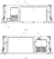
- FIG. 1 is a front-view schematic structural diagram of a double-side expansion cabin type mobile nucleic acid detection laboratory of the present disclosure
- FIG. 2 is a vertical-view schematic structural diagram of the double-side expansion cabin type mobile nucleic acid detection laboratory of the present disclosure
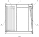
- FIG. 3 is a left-view schematic structural diagram of the double-side expansion cabin type mobile nucleic acid detection laboratory of the present disclosure
- FIG. 4 is a right-view schematic structural diagram of the double-side expansion cabin type mobile nucleic acid detection laboratory of the present disclosure
- FIG. 5 is a cross-sectional schematic diagram of the double-side expansion cabin type mobile nucleic acid detection laboratory of the present disclosure when folded;
- FIG. 1 is a front-view schematic structural diagram of a double-side expansion cabin type mobile nucleic acid detection laboratory of the present disclosure
- FIG. 2 is a vertical-view schematic structural diagram of the double-side expansion cabin type mobile nucleic acid detection laboratory of the present disclosure
- FIG. 3 is a left-view schematic structural diagram of the double-side expansion
- FIG. 6 is an internal layout diagram of the double-side expansion cabin type mobile nucleic acid detection laboratory of the present disclosure
- FIG. 7 is a schematic structural diagram of an expansion cabin of the double-side expansion cabin type mobile nucleic acid detection laboratory of the present disclosure
- FIG. 8 is a schematic structural diagram of an expansion cabin in other implementation manners of the double-side expansion cabin type mobile nucleic acid detection laboratory of the present disclosure
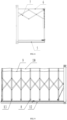
- FIG. 9 is a schematic structural diagram of an expansion tent of the double-side expansion cabin type mobile nucleic acid detection laboratory of the present disclosure.
- the present disclosure provides a double-side expansion cabin type mobile nucleic acid detection laboratory, including a fixed cabin 1, an expansion cabin 2, and an expansion tent 3.
- the expansion cabin 2 and the expansion tent 3 are separately connected to the fixed cabin 1. Both the expansion cabin 2 and the expansion tent 3 can be folded. When completely folded, the expansion cabin 2 and the expansion tent 3 are located in the fixed cabin 1. When the expansion cabin 2 and the expansion tent 3 are unfolded, both the expansion cabin 2 and the expansion tent 3 communicate with the fixed cabin 1.
- An equipment room 17 and a central control area 19 are arranged in the fixed cabin 1.
- the expansion cabin 2 serves as a preparation room 15 and a PCR room 21.
- the expansion tent 3 serves as a core workroom 18 and a liquid preparation room 20.
- a buffer room 16 is arranged in each of the fixed cabin 1, the expansion cabin 2, and the expansion tent 3.
- the expansion tent 3 is in sealed connection with the fixed cabin 1.
- the expansion tent 3 is large in size after being unfolded, and serves as the core workroom 18 and the liquid preparation room 20, which increases the operation space.
- both the expansion cabin 2 and the expansion tent 3 can be unfolded, and are located in the fixed cabin 1 after being folded, so the double-side expansion cabin type mobile nucleic acid detection laboratory has the advantages of small size after being folded and large operation area after being unfolded, thereby facilitating the transportation of the laboratory, and improving the flexibility and convenience of the double-side expansion cabin type mobile nucleic acid detection laboratory.
- the fixed cabin 1 may be connected to a lifting device 4.
- the lifting device 4 can drive the fixed cabin 1 to ascend, descend, or move, so as to facilitate the movement and transportation of the fixed cabin 1.
- the expansion cabin 2 includes a first base plate 5, a cabin body 6, and a bracket 7.
- the first base plate 5 is hinged to the fixed cabin 1.
- the cabin body 6 is connected to the first base plate 5.
- the cabin body 6 is made of a flexible material.
- the bracket 7 is connected to the first base plate 5 and the cabin body 6. When a relative angle between the first base plate 5 and the fixed cabin 1 changes, the bracket 7 can drive the cabin body 6 to move. The rotation of the bracket 7 can drive the flexible cabin body 6 to unfold and fold.
- the first base plate 5 is hinged to the fixed cabin 1. When the cabin body 6 is unfolded completely, the first base plate 5 is parallel to the ground, and when the cabin body 6 is completely folded, the first base plate 5 is flush with a side wall of the fixed cabin 1.
- the first base plate 5 is hinged to the bottom of the fixed cabin 1.
- the bracket 7 includes first connecting rods 701, a second connecting rod 702, first long support rods 703, and a second long support rod 704.
- One end of the first long support rod 703 is hinged to one end, far away from the fixed cabin 1, of the first base plate 5.
- the second long support rod 704 is connected to the top, far away from the fixed cabin 1, of the cabin body 6.
- the other end of the first long support rod 703 is hinged to one end of the second long support rod 704.
- One end of the first connecting rod 701 is hinged to the top of the fixed cabin 1, and the other end of the first connecting rod 701 is hinged to the first long support rod 703.
- a hinge point of the first connecting rod 701 and the first long support rod 703 is located between a hinge point of the first long support rod 703 and the second long support rod 704 and a hinge point of the first long support rod 703 and the first base plate 5.
- the second connecting rod 702 is connected to the top of the cabin body 6.
- One end of the second connecting rod 702 is hinged to the second long support rod 704.
- a hinge point of the second connecting rod 702 and the second long support rod 704 is located between a hinge point of the second long support rod 704 and the first long support rod 703 and a hinge point of the second long support rod 704 and the cabin body 6.
- a driving cylinder is arranged between the first base plate 5 and the fixed cabin 1. The driving cylinder pushes the first base plate 5.
- the first base plate 5 rotates around the fixed cabin 1 to drive the first long support rod 703 and the second long support rod 704 to rotate.
- the first connecting rods 701 and the second connecting rod 702 are respectively connected to the cabin body 6, the first long support rods 703 and the second long support rod 704 to drive the cabin body 6 to unfold.
- the driving cylinder drives the first base plate 5 to rotate.
- the first long support rods 703 and the second long support rod 704 rotate and drive, together with the first connecting rods 701 and the second connecting rod 702, the flexible cabin body 6 to fold and be gathered in the fixed cabin 1.
- a second base plate 8 is overturned to be flush with the side surface of the fixed cabin 1.
- Both the second long support rod 704 and the second connecting rod 702 are U-shaped rods.
- the two opposite ends of the second long support rod 704 are respectively connected to the two first long support rods 703.
- the two opposite ends of the second connecting rod 702 are respectively connected to the two opposite ends of the second long support rod 704.
- the bottoms of the second long support rod 704 and the second connecting rod 702 are separately connected to the cabin body 6.
- the structure of the bracket 7 of the expansion cabin 2 of the present disclosure is not limited to the above structure.
- the bracket 7 shall be able to realize the folding and unfolding of the cabin body 6.
- the bracket 7 is of a rhombus-shaped telescopic frame structure.
- the bracket 7 is connected to the top of the cabin body 6. When the second base plate 8 is overturned, the bracket 7 can drive the cabin body 6 to unfold and fold.
- the expansion tent 3 includes a second base plate 8, an inner tent 9, an outer tent 10, and a telescopic skeleton 11.
- the second base plate 8 is hinged to the fixed cabin 1.
- a driving cylinder is arranged between the second base plate 8 and the fixed cabin 1. The driving cylinder can drive the second base plate 8 to unfold.
- One end of the telescopic skeleton 11 is connected to the fixed cabin 1.
- the inner tent 9 is connected to the telescopic skeleton 11.
- the inner tent 9 is in sealed connection with the fixed cabin 1 to ensure the air tightness in the tent after the inner tent 9 is connected to the fixed cabin 1.
- the telescopic skeleton 11 can stretch and retract.
- the telescopic skeleton 11 can drive the inner tent 9 to move in the direction far away from the fixed cabin 1 and be tiled on the second base plate 8. After the second base plate 8 is unfolded, the telescopic skeleton 11 drives the inner tent 9 to unfold, the outer tent 10 is detachably connected to the inner tent 9. The outer tent 10 is additionally mounted after the inner tent 9 is unfolded. Both the inner tent 9 and the outer tent 10 are made of a flexible material. There is a gap between the inner tent 9 and the outer tent 10, which can achieve a heat insulating effect.
- the expansion tent 3 further includes a support rail 12.
- the support rail 12 is arranged at the bottom of the fixed cabin 1 in a sliding manner. When the expansion tent 3 needs to be unfolded, first, the support rail 12 is pulled out.
- the second base plate 8 is located at the top of the support rail 12 after being unfolded.
- the support rail 12 can support the second base plate 8 to improve the stability of the expansion tent 3.
- the expansion tent 3 may also be fixed by tent pegs and wind ropes, so as to further improve the structural strength of the expansion tent 3.
- the second base plate 8 is of a foldable structure.
- the second base plate 8 can be pressed against the support rail 12.
- the second base plate 8 includes two plate bodies. One end of one of the plate bodies is hinged to the fixed cabin 1. The opposite end of the plate body is hinged to the other plate body.
- the second base plate 8 adopts a split structure, so that the use area of the expansion tent 3 is increased without affecting the size of the laboratory after the expansion tent 3 is gathered, thereby improving the applicability of the laboratory.
- the telescopic skeleton 11 includes a plurality of sliding frames.
- the plurality of the sliding frames is connected through rhombus-shaped telescopic frames.
- the inner tent 9 is arranged inside the sliding frames. Reciprocating movement of the sliding frames along the second base plate 8 can drive the inner tent 9 to fold or unfold. After the inner tent 9 is completely unfolded, the outer tent 10 is connected to the inner tent 9 for mounting, which improves the convenience in operation.
- pulley wheels 13 are arranged at the bottom of the sliding frames, a slide rail that is adapted to the pulley wheels 13 is arranged on the second base plate 8, which ensures the movement trajectory of the sliding frames.
- the pulley wheels 13 are arranged on the slide rail in a sliding manner, which prevents the dislocation of the sliding frames from affecting the work of the expansion tent 3.
- the expansion cabin 2 and the expansion tent 3 are respectively arranged on the two opposite sides of the fixed cabin 1.
- the fixed cabin 1 lands onto the ground, and the expansion cabin 2 and the expansion tent 3 are folded, which improves the convenience in operation of the laboratory.
- both the expansion cabin 2 and the expansion tent 3 can be unfolded, and are located in the fixed cabin 1 after being folded, so the double-side expansion cabin type mobile nucleic acid detection laboratory has the advantages of small size after being folded and large operation area after being unfolded, thereby facilitating the transportation of the laboratory, and improving the flexibility and convenience of the double-side expansion cabin type mobile nucleic acid detection laboratory.
- the equipment room 17 and the central control area 19 are arranged in the fixed cabin 1.
- the expansion cabin 2 serves as the preparation room 15 and the PCR room 21.
- the expansion tent 3 serves as the core workroom 18 and the liquid preparation room 20.
- the buffer room 16 is arranged in each of the fixed cabin 1, the expansion cabin 2, and the expansion tent 3.
- a liftable mast is mounted outside the fixed cabin 1.
- a lighting device and a camera are mounted on the mast.
- the central control area 19 is arranged in the laboratory.
- a control system and a UPS are arranged in the central control area 19, where the UPS mainly supplies power to laboratory supply fans, exhaust fans, lighting, and instruments, equipment and control systems in the laboratory.
- a high efficiency filter is arranged at an exhaust outlet of the core workroom 18.
- a scanning leak detection and sampling device is arranged downstream of the high efficiency filter, which can realize in-situ leak detection of the high efficiency filter. Exhaust outlets are fitted in the buffer rooms 16, the PCR room 21, and the preparation room 15. High efficiency filters are arranged at the exhaust outlets.
- Exhaust pipelines are mounted in a side wall, and a downstream aerosol sampling port is mounted on a downstream pipeline of each high efficiency filter.
- the exhaust air of the core workroom 18, the buffer rooms 16, and the preparation room 15 is finally collected into an exhaust static pressure box.
- Two exhaust fans are mounted in the exhaust static pressure box.
- Air supply of the laboratory is supplied into each of the core workroom 18, the buffer rooms 16, the liquid preparation room 20, the PCR room 21, and the preparation room 15 after passing through a primary efficiency filter, a medium efficiency filter, an air conditioning unit, and a high efficiency filter.
- a communicating door is arranged between every two of the core workroom 18, the buffer rooms 16, the preparation room 15, and the equipment room 17. The arrangement of the communicating doors is a common method used by those skilled in the art, which will not be described in detail here.
Landscapes
- Engineering & Computer Science (AREA)
- Architecture (AREA)
- Civil Engineering (AREA)
- Structural Engineering (AREA)
- Physics & Mathematics (AREA)
- Electromagnetism (AREA)
- Health & Medical Sciences (AREA)
- Public Health (AREA)
- Apparatus Associated With Microorganisms And Enzymes (AREA)
Description
- The present disclosure relates to the technical field of biosafety protection equipment and peripheral supporting facilities thereof, and in particular to a double-side expansion cabin type mobile nucleic acid detection laboratory.
- Global infectious disease outbreaks occur frequently. In this century, many major outbreaks, such as SARS, H5N1 avian influenza, H1N1 influenza, and H7N9 avian influenza, have successively occurred in China. Public health and safety issue has become an important factor that seriously affects people's health, economic development, and social stability in China. International threat of high-risk pathogenic microorganisms is increasing, so does the risk of imported infectious diseases in China. However, some countries have weak relevant biosafety protection capabilities and lack of biosafety facilities, which increase the threat of the high-risk pathogenic microorganisms.
- Developed countries in Europe and the United States have successively developed fast-deployable mobile biosafety third-level laboratories to ensure biosafety in local and overseas missions, with efficient emergency prevention and control capabilities for epidemics. In recent years, China has developed vehicle-mounted mobile biosafety laboratories, which play an important role in microbiological detection. However, the vehicle-mounted mobile biosafety laboratories of China also expose the disadvantages: the existing mobile laboratory adopts a vehicle cabin type structure, which consists of two cabins, so it is large in size, poor in transportation convenience, and difficult to transport over long distances, thereby resulting in that it is difficult to meet the needs of rapid detection of the pathogenic microorganisms in epidemic areas. The nucleic acid detection method which is a main method for pathogenic microorganism detection currently needs to be carried out in a PCR laboratory. However, functional layouts of existing mobile laboratories are difficult to meet the requirements on PCR detection.
- In the patent application with publication number
US2011/132421 A1 , a portable expandable shelter includes an enclosure with one or more movable portions such as a side or end, and further includes a foldable frame configured and arranged for operation in unison with movement of the movable portion of the enclosure. This example of the portable expandable shelter also includes a cover that encloses at least a portion of a space defined by the movable portion and the foldable frame. - The patent application with publication number
CN110656790A discloses an expanded intelligent shelter. The expanded intelligent shelter solves the problems in the prior art that the interior space is fixed and narrow, and has weak natural illumination. The expanded intelligent shelter comprises a shelter main body, wherein the entire surface or part of at least one side of the shelter main body is a movable side plate; after being expanded and flatly laid, the movable side plate is a spreading wing platform; a tent structure matched with the spreading wing platform is stored in the shelter main body; the tent structure is constructed on the spreading wing platform to form a side wing command room; the side wing command room is connected to the inner space of the shelter main body to jointly form a shelter command room; and the movable side plate is provided with a driving mechanism. The used space of the interior of the shelter can be effectively expanded, and meanwhile the sufficient natural illumination is ensured; and the interior space of the shelter is spacious and bright, and thus, the command efficiency of the shelter is improved. - Therefore, how to change the present situations, in the prior art, that an expandable mobile nucleic acid detection laboratory is large in size, poor in transportation convenience, and difficult to transport over long distances, and the functional layouts do not meet the requirements of PCR detection, becomes an urgent problem to be solved by those skilled in the art.
- The objective of the present disclosure is to provide a double-side expansion cabin type mobile nucleic acid detection laboratory to solve the problems in the prior art, so as to facilitate the transportation and improve the convenience of vehicle-mounted mobile nucleic acid detection laboratories.
- To achieve the above objective, the present disclosure provides the following technical solution: the present disclosure provides a double-side expansion cabin type mobile nucleic acid detection laboratory, including a fixed cabin, an expansion cabin, and an expansion tent; an equipment room and a central control area are arranged in the fixed cabin; the expansion cabin serves as a preparation room and a PCR room; the expansion tent serves as a core workroom and a liquid preparation room; a buffer room is arranged in each of the fixed cabin, the expansion cabin, and the expansion tent; the expansion cabin and the expansion tent are separately connected to the fixed cabin; both the expansion cabin and the expansion tent can be folded; when completely folded, the expansion cabin and the expansion tent are located in the fixed cabin; when the expansion cabin and the expansion tent are unfolded, both the expansion cabin and the expansion tent communicate with the fixed cabin; the expansion tent is in sealed connection with the fixed cabin.
- Preferably, the expansion cabin includes a first base plate, a cabin body, and a bracket. The first base plate is hinged to the fixed cabin. The cabin body is connected to the first base plate. The cabin body is made of a flexible material. The bracket is connected to the first base plate and the cabin body. When a relative angle between the first base plate and the fixed cabin changes, the bracket can drive the cabin body to move.
- Preferably, the first base plate is hinged to the bottom of the fixed cabin. The bracket includes first connecting rods, a second connecting rod, first long support rods, and a second long support rod. One end of the first long support rod is hinged to one end, far away from the fixed cabin, of the first base plate. The second long support rod is connected to the top, far away from the fixed cabin, of the cabin body. The other end of the first long support rod is hinged to one end of the second long support rod. One end of the first connecting rod is hinged to the top of the fixed cabin, and the other end of the first connecting rod is hinged to the first long support rod. A hinge point of the first connecting rod and the first long support rod is located between a hinge point of the first long support rod and the second long support rod and a hinge point of the first long support rod and the first base plate. The second connecting rod is connected to the top of the cabin body. One end of the second connecting rod is hinged to the second long support rod. A hinge point of the second connecting rod and the second long support rod is located between a hinge point of the second long support rod and the first long support rod and a hinge point of the second long support rod and the cabin body.
- Preferably, there are two first long support rods and two first connecting rods. Both the second long support rod and the second connecting rod are U-shaped rods. The two opposite ends of the second long support rod are respectively connected to the two first long support rods. The two opposite ends of the second connecting rod are respectively connected to the two opposite ends of the second long support rod. The bottoms of the second long support rod and the second connecting rod are separately connected to the cabin body.
- The expansion tent includes a second base plate, an inner tent, an outer tent, and a telescopic skeleton. The second base plate is hinged to the fixed cabin. One end of the telescopic skeleton is connected to the fixed cabin. The inner tent is connected to the telescopic skeleton. The outer tent is arranged outside the telescopic skeleton. The inner tent is in sealed connection with the fixed cabin. The telescopic skeleton can stretch and retract. The telescopic skeleton can drive the inner tent to move in a direction far away from the fixed cabin and be tiled to the second base plate. The outer tent is detachably connected to the inner tent. Both the inner tent and the outer tent are made of a flexible material.
- Preferably, the expansion tent further includes a support rail. The support rail, which is used for supporting the second base plate, is arranged at the bottom of the fixed cabin in a sliding manner.
- Preferably, the second base plate is of a foldable structure. The second base plate can be pressed against the support rail. The second base plate includes two plate bodies, where one end of one of the plate bodies is hinged to the fixed cabin, and the opposite end of the plate body is hinged to the other plate body.
- Preferably, the telescopic skeleton includes a plurality of sliding frames. The plurality of the sliding frames is connected through rhombus-shaped telescopic frames. The inner tent is arranged inside the sliding frames. Reciprocating movement of the sliding frames along the second base plate can drive the inner tent to fold or unfold.
- Preferably, pulley wheels are arranged at the bottoms of the sliding frames. A slide rail that is adapted to the pulley wheels is arranged on the second base plate. The pulley wheels are arranged on the slide rail in a sliding manner.
- Preferably, the expansion cabin and the expansion tent are respectively arranged on two opposite sides of the fixed cabin.
- Compared with the prior art, the present disclosure achieves the following technical effects: the double-side expansion cabin type mobile nucleic acid detection laboratory of the present disclosure includes the fixed cabin, the expansion cabin, and the expansion tent. The expansion cabin and the expansion tent are separately connected to the fixed cabin. Both the expansion cabin and the expansion tent can be folded. When completely folded, the expansion cabin and the expansion tent are located in the fixed cabin. When the expansion cabin and the expansion tent are unfolded, both the expansion cabin and the expansion tent communicate with the fixed cabin. The expansion tent is in sealed connection with the fixed cabin. The equipment room and the central control area are arranged in the fixed cabin. The expansion cabin serves as the preparation room and the PCR room. The expansion tent serves as the core workroom and the liquid preparation room. The buffer room is arranged in each of the fixed cabin, the expansion cabin, and the expansion tent. According to the double-side expansion cabin type mobile nucleic acid detection laboratory of the present disclosure, both the expansion cabin and the expansion tent can be folded and unfolded automatically. The expansion cabin and the expansion tent are located in the fixed cabin after being folded, so the double-side expansion cabin type mobile nucleic acid detection laboratory has the advantages of small size after being folded and large operation area after being unfolded, thereby facilitating the transportation of the laboratory, and improving the flexibility and convenience of the double-side expansion cabin type mobile nucleic acid detection laboratory.
- To describe the technical solutions in the embodiments of the present disclosure or in the prior art more clearly, the following briefly describes the accompanying drawings required for describing the embodiments. Apparently, the accompanying drawings in the following description show merely some embodiments of the present disclosure, and those of ordinary skill in the art may still derive other drawings from these accompanying drawings without creative efforts.
-
FIG. 1 is a front-view schematic structural diagram of a double-side expansion cabin type mobile nucleic acid detection laboratory of the present disclosure; -
FIG. 2 is a vertical-view schematic structural diagram of the double-side expansion cabin type mobile nucleic acid detection laboratory of the present disclosure; -
FIG. 3 is a left-view schematic structural diagram of the double-side expansion cabin type mobile nucleic acid detection laboratory of the present disclosure; -
FIG. 4 is a right-view schematic structural diagram of the double-side expansion cabin type mobile nucleic acid detection laboratory of the present disclosure; -
FIG. 5 is a cross-sectional schematic diagram of the double-side expansion cabin type mobile nucleic acid detection laboratory of the present disclosure when folded; -
FIG. 6 is an internal layout diagram of the double-side expansion cabin type mobile nucleic acid detection laboratory of the present disclosure; -
FIG. 7 is a schematic structural diagram of an expansion cabin of the double-side expansion cabin type mobile nucleic acid detection laboratory of the present disclosure; -
FIG. 8 is a schematic structural diagram of an expansion cabin in other implementation manners of the double-side expansion cabin type mobile nucleic acid detection laboratory of the present disclosure; -
FIG. 9 is a schematic structural diagram of an expansion tent of the double-side expansion cabin type mobile nucleic acid detection laboratory of the present disclosure. - In the drawings: 1-fixed cabin; 2-expansion cabin; 3-expansion tent; 4-lifting device; 5-first base plate; 6-cabin body; 7-bracket; 701-first connecting rod; 702-second connecting rod; 703-first long support rod; 704-second long support rod; 8-second base plate; 9-inner tent; 10-outer tent; 11-telescopic skeleton; 12-support rail; 13-pulley wheel; 14-walking wheel; 15-preparation room; 16-buffer room; 17-equipment room; 18-core workroom; 19-central control area; 20-liquid preparation room; 21-PCR room.
- The technical solutions in the embodiments of the present disclosure will be clearly and completely described herein below with reference to the accompanying drawings in the embodiments of the present disclosure. Apparently, the described embodiments are merely part rather than all of the embodiments of the present disclosure.
- The objective of the present disclosure is to provide a double-side expansion cabin type mobile nucleic acid detection laboratory to solve the problems in the prior art, so as to facilitate the transportation and improve the convenience of the vehicle-mounted mobile nucleic acid detection laboratories .
- In order to make the above objective, features, and advantages of the present disclosure more apparent and more comprehensible, the present disclosure is further described in detail below with reference to the accompanying drawings and specific implementation manners.
- Please refer to
FIGs. 1 to 9 , whereFIG. 1 is a front-view schematic structural diagram of a double-side expansion cabin type mobile nucleic acid detection laboratory of the present disclosure;FIG. 2 is a vertical-view schematic structural diagram of the double-side expansion cabin type mobile nucleic acid detection laboratory of the present disclosure;FIG. 3 is a left-view schematic structural diagram of the double-side expansion cabin type mobile nucleic acid detection laboratory of the present disclosure;FIG. 4 is a right-view schematic structural diagram of the double-side expansion cabin type mobile nucleic acid detection laboratory of the present disclosure;FIG. 5 is a cross-sectional schematic diagram of the double-side expansion cabin type mobile nucleic acid detection laboratory of the present disclosure when folded;FIG. 6 is an internal layout diagram of the double-side expansion cabin type mobile nucleic acid detection laboratory of the present disclosure;FIG. 7 is a schematic structural diagram of an expansion cabin of the double-side expansion cabin type mobile nucleic acid detection laboratory of the present disclosure;FIG. 8 is a schematic structural diagram of an expansion cabin in other implementation manners of the double-side expansion cabin type mobile nucleic acid detection laboratory of the present disclosure;FIG. 9 is a schematic structural diagram of an expansion tent of the double-side expansion cabin type mobile nucleic acid detection laboratory of the present disclosure. - The present disclosure provides a double-side expansion cabin type mobile nucleic acid detection laboratory, including a fixed
cabin 1, anexpansion cabin 2, and anexpansion tent 3. Theexpansion cabin 2 and theexpansion tent 3 are separately connected to the fixedcabin 1. Both theexpansion cabin 2 and theexpansion tent 3 can be folded. When completely folded, theexpansion cabin 2 and theexpansion tent 3 are located in the fixedcabin 1. When theexpansion cabin 2 and theexpansion tent 3 are unfolded, both theexpansion cabin 2 and theexpansion tent 3 communicate with the fixedcabin 1. Anequipment room 17 and acentral control area 19 are arranged in the fixedcabin 1. Theexpansion cabin 2 serves as apreparation room 15 and aPCR room 21. Theexpansion tent 3 serves as acore workroom 18 and aliquid preparation room 20. Abuffer room 16 is arranged in each of the fixedcabin 1, theexpansion cabin 2, and theexpansion tent 3. Theexpansion tent 3 is in sealed connection with the fixedcabin 1. Theexpansion tent 3 is large in size after being unfolded, and serves as thecore workroom 18 and theliquid preparation room 20, which increases the operation space. - According to the double-side expansion cabin type mobile nucleic acid detection laboratory of the present disclosure, both the
expansion cabin 2 and theexpansion tent 3 can be unfolded, and are located in the fixedcabin 1 after being folded, so the double-side expansion cabin type mobile nucleic acid detection laboratory has the advantages of small size after being folded and large operation area after being unfolded, thereby facilitating the transportation of the laboratory, and improving the flexibility and convenience of the double-side expansion cabin type mobile nucleic acid detection laboratory. It should be noted that, the fixedcabin 1 may be connected to alifting device 4. Thelifting device 4 can drive the fixedcabin 1 to ascend, descend, or move, so as to facilitate the movement and transportation of the fixedcabin 1. - The
expansion cabin 2 includes afirst base plate 5, acabin body 6, and abracket 7. Thefirst base plate 5 is hinged to the fixedcabin 1. Thecabin body 6 is connected to thefirst base plate 5. Thecabin body 6 is made of a flexible material. Thebracket 7 is connected to thefirst base plate 5 and thecabin body 6. When a relative angle between thefirst base plate 5 and the fixedcabin 1 changes, thebracket 7 can drive thecabin body 6 to move. The rotation of thebracket 7 can drive theflexible cabin body 6 to unfold and fold. Thefirst base plate 5 is hinged to the fixedcabin 1. When thecabin body 6 is unfolded completely, thefirst base plate 5 is parallel to the ground, and when thecabin body 6 is completely folded, thefirst base plate 5 is flush with a side wall of the fixedcabin 1. - Specifically, the
first base plate 5 is hinged to the bottom of the fixedcabin 1. Thebracket 7 includes first connectingrods 701, a second connectingrod 702, firstlong support rods 703, and a secondlong support rod 704. One end of the firstlong support rod 703 is hinged to one end, far away from the fixedcabin 1, of thefirst base plate 5. The secondlong support rod 704 is connected to the top, far away from the fixedcabin 1, of thecabin body 6. The other end of the firstlong support rod 703 is hinged to one end of the secondlong support rod 704. One end of the first connectingrod 701 is hinged to the top of the fixedcabin 1, and the other end of the first connectingrod 701 is hinged to the firstlong support rod 703. A hinge point of the first connectingrod 701 and the firstlong support rod 703 is located between a hinge point of the firstlong support rod 703 and the secondlong support rod 704 and a hinge point of the firstlong support rod 703 and thefirst base plate 5. The second connectingrod 702 is connected to the top of thecabin body 6. One end of the second connectingrod 702 is hinged to the secondlong support rod 704. A hinge point of the second connectingrod 702 and the secondlong support rod 704 is located between a hinge point of the secondlong support rod 704 and the firstlong support rod 703 and a hinge point of the secondlong support rod 704 and thecabin body 6. A driving cylinder is arranged between thefirst base plate 5 and the fixedcabin 1. The driving cylinder pushes thefirst base plate 5. Thefirst base plate 5 rotates around the fixedcabin 1 to drive the firstlong support rod 703 and the secondlong support rod 704 to rotate. The first connectingrods 701 and the second connectingrod 702 are respectively connected to thecabin body 6, the firstlong support rods 703 and the secondlong support rod 704 to drive thecabin body 6 to unfold. When thecabin body 6 is gathered, the driving cylinder drives thefirst base plate 5 to rotate. Under an acting force of thefirst base plate 5, the firstlong support rods 703 and the secondlong support rod 704 rotate and drive, together with the first connectingrods 701 and the second connectingrod 702, theflexible cabin body 6 to fold and be gathered in the fixedcabin 1. Asecond base plate 8 is overturned to be flush with the side surface of the fixedcabin 1. - In addition, there are two first
long support rods 703 and two first connectingrods 701. Both the secondlong support rod 704 and the second connectingrod 702 are U-shaped rods. The two opposite ends of the secondlong support rod 704 are respectively connected to the two firstlong support rods 703. The two opposite ends of the second connectingrod 702 are respectively connected to the two opposite ends of the secondlong support rod 704. The bottoms of the secondlong support rod 704 and the second connectingrod 702 are separately connected to thecabin body 6. It should be noted here that the structure of thebracket 7 of theexpansion cabin 2 of the present disclosure is not limited to the above structure. Thebracket 7 shall be able to realize the folding and unfolding of thecabin body 6. In other specific implementation manners of the present disclosure, thebracket 7 is of a rhombus-shaped telescopic frame structure. Thebracket 7 is connected to the top of thecabin body 6. When thesecond base plate 8 is overturned, thebracket 7 can drive thecabin body 6 to unfold and fold. - More specifically, the
expansion tent 3 includes asecond base plate 8, aninner tent 9, anouter tent 10, and atelescopic skeleton 11. Thesecond base plate 8 is hinged to the fixedcabin 1. A driving cylinder is arranged between thesecond base plate 8 and the fixedcabin 1. The driving cylinder can drive thesecond base plate 8 to unfold. One end of thetelescopic skeleton 11 is connected to the fixedcabin 1. Theinner tent 9 is connected to thetelescopic skeleton 11. Theinner tent 9 is in sealed connection with the fixedcabin 1 to ensure the air tightness in the tent after theinner tent 9 is connected to the fixedcabin 1. Thetelescopic skeleton 11 can stretch and retract. Thetelescopic skeleton 11 can drive theinner tent 9 to move in the direction far away from the fixedcabin 1 and be tiled on thesecond base plate 8. After thesecond base plate 8 is unfolded, thetelescopic skeleton 11 drives theinner tent 9 to unfold, theouter tent 10 is detachably connected to theinner tent 9. Theouter tent 10 is additionally mounted after theinner tent 9 is unfolded. Both theinner tent 9 and theouter tent 10 are made of a flexible material. There is a gap between theinner tent 9 and theouter tent 10, which can achieve a heat insulating effect. - To improve the stability of the
expansion tent 3, theexpansion tent 3 further includes asupport rail 12. Thesupport rail 12 is arranged at the bottom of the fixedcabin 1 in a sliding manner. When theexpansion tent 3 needs to be unfolded, first, thesupport rail 12 is pulled out. Thesecond base plate 8 is located at the top of thesupport rail 12 after being unfolded. Thesupport rail 12 can support thesecond base plate 8 to improve the stability of theexpansion tent 3. In other specific implementation manners of the present disclosure, theexpansion tent 3 may also be fixed by tent pegs and wind ropes, so as to further improve the structural strength of theexpansion tent 3. - Further, to increase the use area of the
expansion tent 3, thesecond base plate 8 is of a foldable structure. Thesecond base plate 8 can be pressed against thesupport rail 12. Thesecond base plate 8 includes two plate bodies. One end of one of the plate bodies is hinged to the fixedcabin 1. The opposite end of the plate body is hinged to the other plate body. Thesecond base plate 8 adopts a split structure, so that the use area of theexpansion tent 3 is increased without affecting the size of the laboratory after theexpansion tent 3 is gathered, thereby improving the applicability of the laboratory. - In addition, the
telescopic skeleton 11 includes a plurality of sliding frames. The plurality of the sliding frames is connected through rhombus-shaped telescopic frames. Theinner tent 9 is arranged inside the sliding frames. Reciprocating movement of the sliding frames along thesecond base plate 8 can drive theinner tent 9 to fold or unfold. After theinner tent 9 is completely unfolded, theouter tent 10 is connected to theinner tent 9 for mounting, which improves the convenience in operation. - To improve the work efficiency when the
telescopic skeleton 11 is unfolded and folded,pulley wheels 13 are arranged at the bottom of the sliding frames, a slide rail that is adapted to thepulley wheels 13 is arranged on thesecond base plate 8, which ensures the movement trajectory of the sliding frames. Thepulley wheels 13 are arranged on the slide rail in a sliding manner, which prevents the dislocation of the sliding frames from affecting the work of theexpansion tent 3. - Furthermore, the
expansion cabin 2 and theexpansion tent 3 are respectively arranged on the two opposite sides of the fixedcabin 1. The fixedcabin 1 lands onto the ground, and theexpansion cabin 2 and theexpansion tent 3 are folded, which improves the convenience in operation of the laboratory. - According to the double-side expansion cabin type mobile nucleic acid detection laboratory of the present disclosure, both the
expansion cabin 2 and theexpansion tent 3 can be unfolded, and are located in the fixedcabin 1 after being folded, so the double-side expansion cabin type mobile nucleic acid detection laboratory has the advantages of small size after being folded and large operation area after being unfolded, thereby facilitating the transportation of the laboratory, and improving the flexibility and convenience of the double-side expansion cabin type mobile nucleic acid detection laboratory. In the present specific implementation manner, theequipment room 17 and thecentral control area 19 are arranged in the fixedcabin 1. Theexpansion cabin 2 serves as thepreparation room 15 and thePCR room 21. Theexpansion tent 3 serves as thecore workroom 18 and theliquid preparation room 20. Thebuffer room 16 is arranged in each of the fixedcabin 1, theexpansion cabin 2, and theexpansion tent 3. A liftable mast is mounted outside the fixedcabin 1. A lighting device and a camera are mounted on the mast. Thecentral control area 19 is arranged in the laboratory. A control system and a UPS are arranged in thecentral control area 19, where the UPS mainly supplies power to laboratory supply fans, exhaust fans, lighting, and instruments, equipment and control systems in the laboratory. In addition, a high efficiency filter is arranged at an exhaust outlet of thecore workroom 18. A scanning leak detection and sampling device is arranged downstream of the high efficiency filter, which can realize in-situ leak detection of the high efficiency filter. Exhaust outlets are fitted in thebuffer rooms 16, thePCR room 21, and thepreparation room 15. High efficiency filters are arranged at the exhaust outlets. Exhaust pipelines are mounted in a side wall, and a downstream aerosol sampling port is mounted on a downstream pipeline of each high efficiency filter. The exhaust air of thecore workroom 18, thebuffer rooms 16, and thepreparation room 15 is finally collected into an exhaust static pressure box. Two exhaust fans are mounted in the exhaust static pressure box. Air supply of the laboratory is supplied into each of thecore workroom 18, thebuffer rooms 16, theliquid preparation room 20, thePCR room 21, and thepreparation room 15 after passing through a primary efficiency filter, a medium efficiency filter, an air conditioning unit, and a high efficiency filter. It should be noted that a communicating door is arranged between every two of thecore workroom 18, thebuffer rooms 16, thepreparation room 15, and theequipment room 17. The arrangement of the communicating doors is a common method used by those skilled in the art, which will not be described in detail here. - Specific examples are applied in the present disclosure to illustrate the principle and implementation manner of the present disclosure.
Claims (8)
- A double-side expansion cabin type mobile nucleic acid detection laboratory, comprising a fixed cabin (1), an expansion cabin (2), and an expansion tent (3), wherein an equipment room (17) and a central control area (19) are arranged in the fixed cabin (1); the expansion cabin (2) serves as a preparation room (15) and a PCR room (21); the expansion tent (3) serves as a core workroom (18) and a liquid preparation room (20); a buffer room (16) is arranged in each of the fixed cabin (1), the expansion cabin (2), and the expansion tent (3); the expansion cabin (2) and the expansion tent (3) are separately connected to the fixed cabin (1); both the expansion cabin (2) and the expansion tent (3) can be folded; when completely folded, the expansion cabin (2) and the expansion tent (3) are located in the fixed cabin (1); when the expansion cabin (2) and the expansion tent (3) are unfolded, both the expansion cabin (2) and the expansion tent (3) communicate with the fixed cabin (1); the expansion tent (3) is in sealed connection with the fixed cabin (1);wherein the expansion tent (3) comprises a second base plate (8), an inner tent (9), an outer tent (10), and a telescopic skeleton (11); the second base plate (8) is hinged to the fixed cabin (1); one end of the telescopic skeleton (11) is connected to the fixed cabin (1); the inner tent (9) is connected to the telescopic skeleton (11); the outer tent is arranged outside the telescopic skeleton; the inner tent (9) is in sealed connection with the fixed cabin (1); the telescopic skeleton (11) can stretch and retract; the telescopic skeleton (11) can drive the inner tent (9) to move in a direction far away from the fixed cabin (1) and be tiled to the second base plate (8); the outer tent (10) is detachably connected to the inner tent (9); both the inner tent and the outer tent are made of a flexible material;wherein the core workroom (18) is provided at an exhaust outlet thereof with a first high efficiency filter, and a scanning leak detection and sampling device is arranged downstream of the first high efficiency filter, to allow in-situ leak detection of the first high efficiency filter; the buffer room (16), the PCR room (21), and the preparation room (15) each are provided at a respective exhaust outlet with a second high efficiency filter, respective exhaust pipelines are mounted in a side wall of the laboratory; and a downstream aerosol sampling port is mounted on a downstream pipeline of the second high efficiency filter; exhausted air from the core workroom (18), the buffer room (16), and the preparation room (15) is collected into an exhaust static pressure box in which two exhaust fans are mounted; external air is supplied into each of the core workroom (18), the buffer room (16), the liquid preparation room (20), the PCR room (21), and the preparation room (15) after passing through a primary efficiency filter, a medium efficiency filter, an air conditioning unit, and a third high efficiency filter, among which communicating doors are provided.
- The double-side expansion cabin type mobile nucleic acid detection laboratory according to claim 1, wherein the expansion cabin (2) comprises a first base plate (5), a cabin body (6), and a bracket (7); the first base plate (5) is hinged to the fixed cabin (1); the cabin body (6) is connected to the first base plate (5); the cabin body (6) is made of a flexible material; the bracket (7) is connected to the first base plate (5) and the cabin body (6); when a relative angle between the first base plate (5) and the fixed cabin (1) changes, the bracket (7) can drive the cabin body (6) to move
- The double-side expansion cabin type mobile nucleic acid detection laboratory according to claim 2, wherein the first base plate (5) is hinged to the bottom of the fixed cabin (1); the bracket (7) comprises first connecting rods (701), a second connecting rod (702), first long support rods (703), and a second long support rod (704); one end of the first long support rod (703) is hinged to one end, far away from the fixed cabin (1), of the first base plate (5); the second long support rod (704) is connected to the top, far away from the fixed cabin (1), of the cabin body (6); the other end of the first long support rod (703) is hinged to one end of the second long support rod (704); one end of the first connecting rod (701) is hinged to the top of the fixed cabin (1), and the other end of the first connecting rod (701) is hinged to the first long support rod (703); a hinge point of the first connecting rod (701) and the first long support rod (703) is located between a hinge point of the first long support rod (703) and the second long support rod (704) and a hinge point of the first long support rod (703) and the first base plate (5); the second connecting rod (702) is connected to the top of the cabin body (6); one end of the second connecting rod (702) is hinged to the second long support rod (704); a hinge point of the second connecting rod (702) and the second long support rod (704) is located between a hinge point of the second long support rod (704) and the first long support rod (703) and a hinge point of the second long support rod (704) and the cabin body (6).
- The double-side expansion cabin type mobile nucleic acid detection laboratory according to claim 3, wherein there are two first long support rods (703)and two first connecting rods (701); both the second long support rod (704) and the second connecting rod (702) are U-shaped rods; the two opposite ends of the second long support rod (704) are respectively connected to the two first long support rods(703); the two opposite ends of the second connecting rod (702) are respectively connected to the two opposite ends of the second long support rod (704); the bottoms of the second long support rod (704) and the second connecting rod (702) are separately connected to the cabin body (6).
- The double-side expansion cabin type mobile nucleic acid detection laboratory according to claim 1, wherein the expansion tent (3) further comprises a support rail (12); the support rail (12) which is used for supporting the second base plate (8) is arranged at the bottom of the fixed cabin (1) in a sliding manner.
- The double-side expansion cabin type mobile nucleic acid detection laboratory according to claim 5, wherein the second base plate (8) is of a foldable structure; the second base plate (8) can be pressed against the support rail (12); the second base plate (8) comprises two plate bodies, wherein one end of one of the plate bodies is hinged to the fixed cabin (1), and the opposite end of the plate body is hinged to the other plate body.
- The double-side expansion cabin type mobile nucleic acid detection laboratory according to claim 6, wherein the telescopic skeleton (11) comprises a plurality of sliding frames; the plurality of the sliding frames is connected through rhombus-shaped telescopic frames; the inner tent (9) is arranged inside the sliding frames; reciprocating movement of the sliding frames along the second base plate (8) can drive the inner tent (9) to fold or unfold.
- The double-side expansion cabin type mobile nucleic acid detection laboratory according to claim 7, wherein pulley wheels (13) are arranged at the bottom of the sliding frames; a slide rail that is adapted to the pulley wheels (13) is arranged on the second base plate (8); the pulley wheels are arranged on the slide rail in a sliding manner.
Applications Claiming Priority (1)
| Application Number | Priority Date | Filing Date | Title |
|---|---|---|---|
| CN202010566333.6A CN111576941B (en) | 2020-06-19 | 2020-06-19 | A double-sided expansion square cabin mobile nucleic acid detection laboratory |
Publications (2)
| Publication Number | Publication Date |
|---|---|
| EP3926113A1 EP3926113A1 (en) | 2021-12-22 |
| EP3926113B1 true EP3926113B1 (en) | 2024-01-17 |
Family
ID=72125797
Family Applications (1)
| Application Number | Title | Priority Date | Filing Date |
|---|---|---|---|
| EP21155667.5A Active EP3926113B1 (en) | 2020-06-19 | 2021-02-08 | Double-side expansion cabin type mobile nucleic acid detection laboratory |
Country Status (2)
| Country | Link |
|---|---|
| EP (1) | EP3926113B1 (en) |
| CN (1) | CN111576941B (en) |
Families Citing this family (31)
| Publication number | Priority date | Publication date | Assignee | Title |
|---|---|---|---|---|
| KR101956229B1 (en) * | 2018-12-04 | 2019-03-08 | 이승욱 | House expander for a camping car |
| CN112302374A (en) * | 2020-10-23 | 2021-02-02 | 山西尚风抑风墙科技有限公司 | Movable detection chamber |
| CN112212439A (en) * | 2020-10-30 | 2021-01-12 | 深圳市巨鼎医疗设备有限公司 | Remove ward with novel exhaust device |
| CN113107264A (en) * | 2021-03-20 | 2021-07-13 | 江苏创元特种装备有限公司 | Rapid unfolding tent connected with shelter |
| CN113700350B (en) * | 2021-09-03 | 2022-09-23 | 无锡市第二人民医院 | Movable positive pressure nucleic acid pharynx swab collecting combined pavilion |
| CN115788112A (en) * | 2021-09-13 | 2023-03-14 | 北京同方洁净技术有限公司 | Vehicle biological decontamination station and rapid construction method and disinfection method thereof |
| CN113931498B (en) * | 2021-10-28 | 2025-06-06 | 军事科学院系统工程研究院卫勤保障技术研究所 | An extended shelter connecting channel structure |
| CN114718189B (en) * | 2022-03-31 | 2025-08-01 | 苏州江南航天机电工业有限公司 | Shelter structural form capable of being expanded in two layers in two directions |
| CN114922291A (en) * | 2022-04-19 | 2022-08-19 | 安徽空间探索科技有限公司 | Expansion type square cabin and expansion method thereof |
| CN114771388A (en) * | 2022-04-20 | 2022-07-22 | 天津大学温州安全(应急)研究院 | Vehicle-mounted hospital with vehicle-mounted account |
| CN115263037B (en) * | 2022-08-14 | 2025-07-08 | 中船海神医疗科技有限公司 | Passage shelter |
| CN115217353A (en) * | 2022-08-15 | 2022-10-21 | 四川科特空调净化有限责任公司 | Positive pressure gas protection nucleic acid sampling analysis operation laboratory |
| CN115680321A (en) * | 2022-10-18 | 2023-02-03 | 西安长峰机电研究所 | A two-way large expansion ratio cabin expansion mechanism |
| CN115822260B (en) * | 2022-12-02 | 2023-11-21 | 中国船舶集团有限公司系统工程研究院 | Expansion method of expandable shelter |
| CN115853319A (en) * | 2022-12-09 | 2023-03-28 | 重庆海润节能技术股份有限公司 | Full-automatic PCR shelter detection laboratory and intelligent environment control system |
| CN116084568B (en) * | 2022-12-22 | 2026-01-13 | 苏州江南航天机电工业有限公司 | Shelter end plate sliding expansion mechanism |
| CN116122660B (en) * | 2022-12-29 | 2025-06-06 | 深圳市乐惠应急科技有限公司 | Multifunctional command cabin |
| CN115992611A (en) * | 2023-03-08 | 2023-04-21 | 中振汉江装备科技有限公司 | A multifunctional modular intelligent shelter |
| CN116378220B (en) * | 2023-05-04 | 2026-01-13 | 常熟华东汽车有限公司 | Side wall translation shelter cabin body expanding mechanism |
| CN116856549A (en) * | 2023-07-05 | 2023-10-10 | 深圳市乐惠应急科技有限公司 | Command shelter convenient to quick deployment |
| CN117779954A (en) * | 2023-09-22 | 2024-03-29 | 江西中船航海仪器有限公司 | A kind of ordinary ward cabin |
| CN117180013A (en) * | 2023-10-09 | 2023-12-08 | 军事科学院系统工程研究院卫勤保障技术研究所 | A medical emergency trailer |
| CN117262048A (en) * | 2023-10-10 | 2023-12-22 | 军事科学院系统工程研究院卫勤保障技术研究所 | A quickly deployable casualty on-site treatment trailer |
| CN117287071B (en) * | 2023-10-10 | 2026-01-13 | 军事科学院系统工程研究院卫勤保障技术研究所 | Expansion shelter |
| CN117224326A (en) * | 2023-10-12 | 2023-12-15 | 军事科学院系统工程研究院卫勤保障技术研究所 | A kind of medical medicine and equipment support cabin |
| CN117159286A (en) * | 2023-10-13 | 2023-12-05 | 军事科学院系统工程研究院卫勤保障技术研究所 | Open-air operation car |
| CN117297889A (en) * | 2023-10-13 | 2023-12-29 | 军事科学院系统工程研究院卫勤保障技术研究所 | A trailer for treating sick and wounded patients |
| CN118441808B (en) * | 2024-05-16 | 2024-10-18 | 南京辰茂新材料科技有限公司 | Multi-functional panel extension shelter of turning over of lightweight |
| CN118911287A (en) * | 2024-08-28 | 2024-11-08 | 上海裕驿科技有限公司 | Expandable functional cabin |
| CN118895818A (en) * | 2024-08-28 | 2024-11-05 | 上海裕驿科技有限公司 | Retractable cabin |
| CN121519778A (en) * | 2025-11-18 | 2026-02-13 | 中国辐射防护研究院 | A retractable tent for nuclear facility decommissioning |
Citations (1)
| Publication number | Priority date | Publication date | Assignee | Title |
|---|---|---|---|---|
| JPH0683865U (en) * | 1993-05-14 | 1994-12-02 | 株式会社トーアスポーツマシーン | Simple building for baseball practice |
Family Cites Families (7)
| Publication number | Priority date | Publication date | Assignee | Title |
|---|---|---|---|---|
| SE505728C2 (en) * | 1994-10-26 | 1997-10-06 | Samina Ltd | Mobile developmentable business premises |
| US5964065A (en) * | 1996-12-20 | 1999-10-12 | San Jose State University Foundation | Advanced surgical suite for trauma casualties (AZTEC) |
| CN2713063Y (en) * | 2004-08-02 | 2005-07-27 | 杭州博日科技有限公司 | Mobile safety laboratory |
| US8622066B2 (en) * | 2009-12-09 | 2014-01-07 | Berg Companies, Inc. | Portable expandable shelter |
| CN205116806U (en) * | 2015-10-14 | 2016-03-30 | 河南冰熊专用车辆制造有限公司 | Expanded medical shelter of vehicular |
| CN109184268B (en) * | 2018-09-18 | 2024-05-28 | 中船第九设计研究院工程有限公司 | A PCR laboratory with environmental barriers |
| CN110656790A (en) * | 2019-10-31 | 2020-01-07 | 史法智 | An expandable smart cabin |
-
2020
- 2020-06-19 CN CN202010566333.6A patent/CN111576941B/en active Active
-
2021
- 2021-02-08 EP EP21155667.5A patent/EP3926113B1/en active Active
Patent Citations (1)
| Publication number | Priority date | Publication date | Assignee | Title |
|---|---|---|---|---|
| JPH0683865U (en) * | 1993-05-14 | 1994-12-02 | 株式会社トーアスポーツマシーン | Simple building for baseball practice |
Also Published As
| Publication number | Publication date |
|---|---|
| CN111576941A (en) | 2020-08-25 |
| EP3926113A1 (en) | 2021-12-22 |
| CN111576941B (en) | 2021-01-08 |
Similar Documents
| Publication | Publication Date | Title |
|---|---|---|
| EP3926113A1 (en) | Double-side expansion cabin type mobile nucleic acid detection laboratory | |
| EP1718811B1 (en) | Expandable container | |
| CN104986094B (en) | A kind of multidimensional Automatic-expanding is camped commander's integrated vehicle | |
| CN107351757A (en) | A kind of folding and retraction formula wing-room, folding and retraction formula compartment and folding and retraction formula caravan | |
| CN113718963A (en) | Folding house | |
| CN103818300A (en) | Outdoor boarding car | |
| CN111749342A (en) | Expanding shelter system | |
| CN203727253U (en) | Field boarding car | |
| CN105270613A (en) | Foldable telescopic six-shaft aircraft | |
| CN201852317U (en) | The support frame of the mobile solar tracking system | |
| CN206501767U (en) | Removable barracks device | |
| CN104601100B (en) | Support mechanism for photovoltaic modules | |
| CN114476149B (en) | Spatial expandable exposure experiment platform based on spherical 5R mechanism | |
| CN207190902U (en) | A kind of folding and retraction formula wing-room, folding and retraction formula compartment and folding and retraction formula caravan | |
| CN114572423A (en) | Myard mechanism-based space expandable exposure experiment platform | |
| CN205469801U (en) | Horn folding device of multiaxis aircraft | |
| CN217294358U (en) | Vehicle-mounted hospital with vehicle-mounted account | |
| CN212326754U (en) | Emergency department uses convenient stretcher | |
| CN117184463A (en) | Quick-assembly and quick-disassembly protective device for spacecraft field transportation and its use method | |
| CN216306960U (en) | Telescopic air pipe device | |
| CN202687174U (en) | Lifting type expansion cabin body | |
| CN222084142U (en) | A homestay space capsule that is easy to transport | |
| CN209163599U (en) | A kind of Multifunction outdoor tent | |
| CN207109623U (en) | A kind of collapsible helicopter airplane parking area | |
| CN101716905A (en) | Roof-telescopic large-volume dining automobile |
Legal Events
| Date | Code | Title | Description |
|---|---|---|---|
| PUAI | Public reference made under article 153(3) epc to a published international application that has entered the european phase |
Free format text: ORIGINAL CODE: 0009012 |
|
| STAA | Information on the status of an ep patent application or granted ep patent |
Free format text: STATUS: REQUEST FOR EXAMINATION WAS MADE |
|
| 17P | Request for examination filed |
Effective date: 20210208 |
|
| AK | Designated contracting states |
Kind code of ref document: A1 Designated state(s): AL AT BE BG CH CY CZ DE DK EE ES FI FR GB GR HR HU IE IS IT LI LT LU LV MC MK MT NL NO PL PT RO RS SE SI SK SM TR |
|
| B565 | Issuance of search results under rule 164(2) epc |
Effective date: 20210716 |
|
| STAA | Information on the status of an ep patent application or granted ep patent |
Free format text: STATUS: EXAMINATION IS IN PROGRESS |
|
| RBV | Designated contracting states (corrected) |
Designated state(s): AL AT BE BG CH CY CZ DE DK EE ES FI FR GB GR HR HU IE IS IT LI LT LU LV MC MK MT NL NO PL PT RO RS SE SI SK SM TR |
|
| 17Q | First examination report despatched |
Effective date: 20220726 |
|
| GRAP | Despatch of communication of intention to grant a patent |
Free format text: ORIGINAL CODE: EPIDOSNIGR1 |
|
| STAA | Information on the status of an ep patent application or granted ep patent |
Free format text: STATUS: GRANT OF PATENT IS INTENDED |
|
| INTG | Intention to grant announced |
Effective date: 20230811 |
|
| GRAS | Grant fee paid |
Free format text: ORIGINAL CODE: EPIDOSNIGR3 |
|
| GRAA | (expected) grant |
Free format text: ORIGINAL CODE: 0009210 |
|
| STAA | Information on the status of an ep patent application or granted ep patent |
Free format text: STATUS: THE PATENT HAS BEEN GRANTED |
|
| AK | Designated contracting states |
Kind code of ref document: B1 Designated state(s): AL AT BE BG CH CY CZ DE DK EE ES FI FR GB GR HR HU IE IS IT LI LT LU LV MC MK MT NL NO PL PT RO RS SE SI SK SM TR |
|
| REG | Reference to a national code |
Ref country code: GB Ref legal event code: FG4D |
|
| REG | Reference to a national code |
Ref country code: CH Ref legal event code: EP |
|
| REG | Reference to a national code |
Ref country code: DE Ref legal event code: R096 Ref document number: 602021008605 Country of ref document: DE |
|
| REG | Reference to a national code |
Ref country code: IE Ref legal event code: FG4D |
|
| PGFP | Annual fee paid to national office [announced via postgrant information from national office to epo] |
Ref country code: DE Payment date: 20240307 Year of fee payment: 4 |
|
| REG | Reference to a national code |
Ref country code: LT Ref legal event code: MG9D |
|
| REG | Reference to a national code |
Ref country code: NL Ref legal event code: MP Effective date: 20240117 |
|
| PGFP | Annual fee paid to national office [announced via postgrant information from national office to epo] |
Ref country code: FR Payment date: 20240229 Year of fee payment: 4 |
|
| REG | Reference to a national code |
Ref country code: AT Ref legal event code: MK05 Ref document number: 1650619 Country of ref document: AT Kind code of ref document: T Effective date: 20240117 |
|
| PG25 | Lapsed in a contracting state [announced via postgrant information from national office to epo] |
Ref country code: NL Free format text: LAPSE BECAUSE OF FAILURE TO SUBMIT A TRANSLATION OF THE DESCRIPTION OR TO PAY THE FEE WITHIN THE PRESCRIBED TIME-LIMIT Effective date: 20240117 |
|
| PG25 | Lapsed in a contracting state [announced via postgrant information from national office to epo] |
Ref country code: NL Free format text: LAPSE BECAUSE OF FAILURE TO SUBMIT A TRANSLATION OF THE DESCRIPTION OR TO PAY THE FEE WITHIN THE PRESCRIBED TIME-LIMIT Effective date: 20240117 |
|
| PG25 | Lapsed in a contracting state [announced via postgrant information from national office to epo] |
Ref country code: IS Free format text: LAPSE BECAUSE OF FAILURE TO SUBMIT A TRANSLATION OF THE DESCRIPTION OR TO PAY THE FEE WITHIN THE PRESCRIBED TIME-LIMIT Effective date: 20240517 |
|
| PG25 | Lapsed in a contracting state [announced via postgrant information from national office to epo] |
Ref country code: LT Free format text: LAPSE BECAUSE OF FAILURE TO SUBMIT A TRANSLATION OF THE DESCRIPTION OR TO PAY THE FEE WITHIN THE PRESCRIBED TIME-LIMIT Effective date: 20240117 |
|
| PG25 | Lapsed in a contracting state [announced via postgrant information from national office to epo] |
Ref country code: GR Free format text: LAPSE BECAUSE OF FAILURE TO SUBMIT A TRANSLATION OF THE DESCRIPTION OR TO PAY THE FEE WITHIN THE PRESCRIBED TIME-LIMIT Effective date: 20240418 |
|
| PG25 | Lapsed in a contracting state [announced via postgrant information from national office to epo] |
Ref country code: HR Free format text: LAPSE BECAUSE OF FAILURE TO SUBMIT A TRANSLATION OF THE DESCRIPTION OR TO PAY THE FEE WITHIN THE PRESCRIBED TIME-LIMIT Effective date: 20240117 Ref country code: RS Free format text: LAPSE BECAUSE OF FAILURE TO SUBMIT A TRANSLATION OF THE DESCRIPTION OR TO PAY THE FEE WITHIN THE PRESCRIBED TIME-LIMIT Effective date: 20240417 |
|
| PG25 | Lapsed in a contracting state [announced via postgrant information from national office to epo] |
Ref country code: ES Free format text: LAPSE BECAUSE OF FAILURE TO SUBMIT A TRANSLATION OF THE DESCRIPTION OR TO PAY THE FEE WITHIN THE PRESCRIBED TIME-LIMIT Effective date: 20240117 |
|
| PG25 | Lapsed in a contracting state [announced via postgrant information from national office to epo] |
Ref country code: AT Free format text: LAPSE BECAUSE OF FAILURE TO SUBMIT A TRANSLATION OF THE DESCRIPTION OR TO PAY THE FEE WITHIN THE PRESCRIBED TIME-LIMIT Effective date: 20240117 |
|
| PG25 | Lapsed in a contracting state [announced via postgrant information from national office to epo] |
Ref country code: RS Free format text: LAPSE BECAUSE OF FAILURE TO SUBMIT A TRANSLATION OF THE DESCRIPTION OR TO PAY THE FEE WITHIN THE PRESCRIBED TIME-LIMIT Effective date: 20240417 Ref country code: NO Free format text: LAPSE BECAUSE OF FAILURE TO SUBMIT A TRANSLATION OF THE DESCRIPTION OR TO PAY THE FEE WITHIN THE PRESCRIBED TIME-LIMIT Effective date: 20240417 Ref country code: LT Free format text: LAPSE BECAUSE OF FAILURE TO SUBMIT A TRANSLATION OF THE DESCRIPTION OR TO PAY THE FEE WITHIN THE PRESCRIBED TIME-LIMIT Effective date: 20240117 Ref country code: IS Free format text: LAPSE BECAUSE OF FAILURE TO SUBMIT A TRANSLATION OF THE DESCRIPTION OR TO PAY THE FEE WITHIN THE PRESCRIBED TIME-LIMIT Effective date: 20240517 Ref country code: HR Free format text: LAPSE BECAUSE OF FAILURE TO SUBMIT A TRANSLATION OF THE DESCRIPTION OR TO PAY THE FEE WITHIN THE PRESCRIBED TIME-LIMIT Effective date: 20240117 Ref country code: GR Free format text: LAPSE BECAUSE OF FAILURE TO SUBMIT A TRANSLATION OF THE DESCRIPTION OR TO PAY THE FEE WITHIN THE PRESCRIBED TIME-LIMIT Effective date: 20240418 Ref country code: FI Free format text: LAPSE BECAUSE OF FAILURE TO SUBMIT A TRANSLATION OF THE DESCRIPTION OR TO PAY THE FEE WITHIN THE PRESCRIBED TIME-LIMIT Effective date: 20240117 Ref country code: ES Free format text: LAPSE BECAUSE OF FAILURE TO SUBMIT A TRANSLATION OF THE DESCRIPTION OR TO PAY THE FEE WITHIN THE PRESCRIBED TIME-LIMIT Effective date: 20240117 Ref country code: BG Free format text: LAPSE BECAUSE OF FAILURE TO SUBMIT A TRANSLATION OF THE DESCRIPTION OR TO PAY THE FEE WITHIN THE PRESCRIBED TIME-LIMIT Effective date: 20240117 Ref country code: AT Free format text: LAPSE BECAUSE OF FAILURE TO SUBMIT A TRANSLATION OF THE DESCRIPTION OR TO PAY THE FEE WITHIN THE PRESCRIBED TIME-LIMIT Effective date: 20240117 |
|
| PG25 | Lapsed in a contracting state [announced via postgrant information from national office to epo] |
Ref country code: PT Free format text: LAPSE BECAUSE OF FAILURE TO SUBMIT A TRANSLATION OF THE DESCRIPTION OR TO PAY THE FEE WITHIN THE PRESCRIBED TIME-LIMIT Effective date: 20240517 Ref country code: PL Free format text: LAPSE BECAUSE OF FAILURE TO SUBMIT A TRANSLATION OF THE DESCRIPTION OR TO PAY THE FEE WITHIN THE PRESCRIBED TIME-LIMIT Effective date: 20240117 |
|
| PG25 | Lapsed in a contracting state [announced via postgrant information from national office to epo] |
Ref country code: SE Free format text: LAPSE BECAUSE OF FAILURE TO SUBMIT A TRANSLATION OF THE DESCRIPTION OR TO PAY THE FEE WITHIN THE PRESCRIBED TIME-LIMIT Effective date: 20240117 Ref country code: PT Free format text: LAPSE BECAUSE OF FAILURE TO SUBMIT A TRANSLATION OF THE DESCRIPTION OR TO PAY THE FEE WITHIN THE PRESCRIBED TIME-LIMIT Effective date: 20240517 Ref country code: PL Free format text: LAPSE BECAUSE OF FAILURE TO SUBMIT A TRANSLATION OF THE DESCRIPTION OR TO PAY THE FEE WITHIN THE PRESCRIBED TIME-LIMIT Effective date: 20240117 Ref country code: LV Free format text: LAPSE BECAUSE OF FAILURE TO SUBMIT A TRANSLATION OF THE DESCRIPTION OR TO PAY THE FEE WITHIN THE PRESCRIBED TIME-LIMIT Effective date: 20240117 |
|
| REG | Reference to a national code |
Ref country code: CH Ref legal event code: PL |
|
| PG25 | Lapsed in a contracting state [announced via postgrant information from national office to epo] |
Ref country code: DK Free format text: LAPSE BECAUSE OF FAILURE TO SUBMIT A TRANSLATION OF THE DESCRIPTION OR TO PAY THE FEE WITHIN THE PRESCRIBED TIME-LIMIT Effective date: 20240117 |
|
| PG25 | Lapsed in a contracting state [announced via postgrant information from national office to epo] |
Ref country code: SM Free format text: LAPSE BECAUSE OF FAILURE TO SUBMIT A TRANSLATION OF THE DESCRIPTION OR TO PAY THE FEE WITHIN THE PRESCRIBED TIME-LIMIT Effective date: 20240117 |
|
| PG25 | Lapsed in a contracting state [announced via postgrant information from national office to epo] |
Ref country code: LU Free format text: LAPSE BECAUSE OF NON-PAYMENT OF DUE FEES Effective date: 20240208 |
|
| REG | Reference to a national code |
Ref country code: DE Ref legal event code: R097 Ref document number: 602021008605 Country of ref document: DE |
|
| PG25 | Lapsed in a contracting state [announced via postgrant information from national office to epo] |
Ref country code: CH Free format text: LAPSE BECAUSE OF NON-PAYMENT OF DUE FEES Effective date: 20240229 |
|
| PG25 | Lapsed in a contracting state [announced via postgrant information from national office to epo] |
Ref country code: EE Free format text: LAPSE BECAUSE OF FAILURE TO SUBMIT A TRANSLATION OF THE DESCRIPTION OR TO PAY THE FEE WITHIN THE PRESCRIBED TIME-LIMIT Effective date: 20240117 Ref country code: CZ Free format text: LAPSE BECAUSE OF FAILURE TO SUBMIT A TRANSLATION OF THE DESCRIPTION OR TO PAY THE FEE WITHIN THE PRESCRIBED TIME-LIMIT Effective date: 20240117 |
|
| PG25 | Lapsed in a contracting state [announced via postgrant information from national office to epo] |
Ref country code: SK Free format text: LAPSE BECAUSE OF FAILURE TO SUBMIT A TRANSLATION OF THE DESCRIPTION OR TO PAY THE FEE WITHIN THE PRESCRIBED TIME-LIMIT Effective date: 20240117 |
|
| PG25 | Lapsed in a contracting state [announced via postgrant information from national office to epo] |
Ref country code: SM Free format text: LAPSE BECAUSE OF FAILURE TO SUBMIT A TRANSLATION OF THE DESCRIPTION OR TO PAY THE FEE WITHIN THE PRESCRIBED TIME-LIMIT Effective date: 20240117 Ref country code: SK Free format text: LAPSE BECAUSE OF FAILURE TO SUBMIT A TRANSLATION OF THE DESCRIPTION OR TO PAY THE FEE WITHIN THE PRESCRIBED TIME-LIMIT Effective date: 20240117 Ref country code: RO Free format text: LAPSE BECAUSE OF FAILURE TO SUBMIT A TRANSLATION OF THE DESCRIPTION OR TO PAY THE FEE WITHIN THE PRESCRIBED TIME-LIMIT Effective date: 20240117 Ref country code: LU Free format text: LAPSE BECAUSE OF NON-PAYMENT OF DUE FEES Effective date: 20240208 Ref country code: EE Free format text: LAPSE BECAUSE OF FAILURE TO SUBMIT A TRANSLATION OF THE DESCRIPTION OR TO PAY THE FEE WITHIN THE PRESCRIBED TIME-LIMIT Effective date: 20240117 Ref country code: DK Free format text: LAPSE BECAUSE OF FAILURE TO SUBMIT A TRANSLATION OF THE DESCRIPTION OR TO PAY THE FEE WITHIN THE PRESCRIBED TIME-LIMIT Effective date: 20240117 Ref country code: CZ Free format text: LAPSE BECAUSE OF FAILURE TO SUBMIT A TRANSLATION OF THE DESCRIPTION OR TO PAY THE FEE WITHIN THE PRESCRIBED TIME-LIMIT Effective date: 20240117 Ref country code: CH Free format text: LAPSE BECAUSE OF NON-PAYMENT OF DUE FEES Effective date: 20240229 |
|
| PG25 | Lapsed in a contracting state [announced via postgrant information from national office to epo] |
Ref country code: MC Free format text: LAPSE BECAUSE OF FAILURE TO SUBMIT A TRANSLATION OF THE DESCRIPTION OR TO PAY THE FEE WITHIN THE PRESCRIBED TIME-LIMIT Effective date: 20240117 |
|
| PLBE | No opposition filed within time limit |
Free format text: ORIGINAL CODE: 0009261 |
|
| STAA | Information on the status of an ep patent application or granted ep patent |
Free format text: STATUS: NO OPPOSITION FILED WITHIN TIME LIMIT |
|
| PG25 | Lapsed in a contracting state [announced via postgrant information from national office to epo] |
Ref country code: MC Free format text: LAPSE BECAUSE OF FAILURE TO SUBMIT A TRANSLATION OF THE DESCRIPTION OR TO PAY THE FEE WITHIN THE PRESCRIBED TIME-LIMIT Effective date: 20240117 |
|
| PG25 | Lapsed in a contracting state [announced via postgrant information from national office to epo] |
Ref country code: IT Free format text: LAPSE BECAUSE OF FAILURE TO SUBMIT A TRANSLATION OF THE DESCRIPTION OR TO PAY THE FEE WITHIN THE PRESCRIBED TIME-LIMIT Effective date: 20240117 |
|
| REG | Reference to a national code |
Ref country code: BE Ref legal event code: MM Effective date: 20240229 |
|
| 26N | No opposition filed |
Effective date: 20241018 |
|
| PG25 | Lapsed in a contracting state [announced via postgrant information from national office to epo] |
Ref country code: IT Free format text: LAPSE BECAUSE OF FAILURE TO SUBMIT A TRANSLATION OF THE DESCRIPTION OR TO PAY THE FEE WITHIN THE PRESCRIBED TIME-LIMIT Effective date: 20240117 |
|
| PG25 | Lapsed in a contracting state [announced via postgrant information from national office to epo] |
Ref country code: BE Free format text: LAPSE BECAUSE OF NON-PAYMENT OF DUE FEES Effective date: 20240229 |
|
| PG25 | Lapsed in a contracting state [announced via postgrant information from national office to epo] |
Ref country code: IE Free format text: LAPSE BECAUSE OF NON-PAYMENT OF DUE FEES Effective date: 20240208 |
|
| PG25 | Lapsed in a contracting state [announced via postgrant information from national office to epo] |
Ref country code: IE Free format text: LAPSE BECAUSE OF NON-PAYMENT OF DUE FEES Effective date: 20240208 Ref country code: BE Free format text: LAPSE BECAUSE OF NON-PAYMENT OF DUE FEES Effective date: 20240229 |
|
| PG25 | Lapsed in a contracting state [announced via postgrant information from national office to epo] |
Ref country code: SI Free format text: LAPSE BECAUSE OF FAILURE TO SUBMIT A TRANSLATION OF THE DESCRIPTION OR TO PAY THE FEE WITHIN THE PRESCRIBED TIME-LIMIT Effective date: 20240117 |
|
| PG25 | Lapsed in a contracting state [announced via postgrant information from national office to epo] |
Ref country code: CY Free format text: LAPSE BECAUSE OF FAILURE TO SUBMIT A TRANSLATION OF THE DESCRIPTION OR TO PAY THE FEE WITHIN THE PRESCRIBED TIME-LIMIT; INVALID AB INITIO Effective date: 20210208 |
|
| REG | Reference to a national code |
Ref country code: DE Ref legal event code: R119 Ref document number: 602021008605 Country of ref document: DE |
|
| PG25 | Lapsed in a contracting state [announced via postgrant information from national office to epo] |
Ref country code: HU Free format text: LAPSE BECAUSE OF FAILURE TO SUBMIT A TRANSLATION OF THE DESCRIPTION OR TO PAY THE FEE WITHIN THE PRESCRIBED TIME-LIMIT; INVALID AB INITIO Effective date: 20210208 |
|
| GBPC | Gb: european patent ceased through non-payment of renewal fee |
Effective date: 20250208 |
|
| PG25 | Lapsed in a contracting state [announced via postgrant information from national office to epo] |
Ref country code: TR Free format text: LAPSE BECAUSE OF FAILURE TO SUBMIT A TRANSLATION OF THE DESCRIPTION OR TO PAY THE FEE WITHIN THE PRESCRIBED TIME-LIMIT Effective date: 20240117 |
|
| PG25 | Lapsed in a contracting state [announced via postgrant information from national office to epo] |
Ref country code: DE Free format text: LAPSE BECAUSE OF NON-PAYMENT OF DUE FEES Effective date: 20250902 |
|
| PG25 | Lapsed in a contracting state [announced via postgrant information from national office to epo] |
Ref country code: GB Free format text: LAPSE BECAUSE OF NON-PAYMENT OF DUE FEES Effective date: 20250208 |
|
| PG25 | Lapsed in a contracting state [announced via postgrant information from national office to epo] |
Ref country code: FR Free format text: LAPSE BECAUSE OF NON-PAYMENT OF DUE FEES Effective date: 20250228 |