EP3922930A1 - Verfahren zum betrieb einer kompressionskälteanlage und zugehörige kompressionskälteanlage - Google Patents
Verfahren zum betrieb einer kompressionskälteanlage und zugehörige kompressionskälteanlage Download PDFInfo
- Publication number
- EP3922930A1 EP3922930A1 EP21177558.0A EP21177558A EP3922930A1 EP 3922930 A1 EP3922930 A1 EP 3922930A1 EP 21177558 A EP21177558 A EP 21177558A EP 3922930 A1 EP3922930 A1 EP 3922930A1
- Authority
- EP
- European Patent Office
- Prior art keywords
- temperature
- value
- refrigerant
- compressor
- correction value
- Prior art date
- Legal status (The legal status is an assumption and is not a legal conclusion. Google has not performed a legal analysis and makes no representation as to the accuracy of the status listed.)
- Granted
Links
Images


Classifications
-
- F—MECHANICAL ENGINEERING; LIGHTING; HEATING; WEAPONS; BLASTING
- F25—REFRIGERATION OR COOLING; COMBINED HEATING AND REFRIGERATION SYSTEMS; HEAT PUMP SYSTEMS; MANUFACTURE OR STORAGE OF ICE; LIQUEFACTION SOLIDIFICATION OF GASES
- F25B—REFRIGERATION MACHINES, PLANTS OR SYSTEMS; COMBINED HEATING AND REFRIGERATION SYSTEMS; HEAT PUMP SYSTEMS
- F25B49/00—Arrangement or mounting of control or safety devices
- F25B49/02—Arrangement or mounting of control or safety devices for compression type machines, plants or systems
-
- F—MECHANICAL ENGINEERING; LIGHTING; HEATING; WEAPONS; BLASTING
- F25—REFRIGERATION OR COOLING; COMBINED HEATING AND REFRIGERATION SYSTEMS; HEAT PUMP SYSTEMS; MANUFACTURE OR STORAGE OF ICE; LIQUEFACTION SOLIDIFICATION OF GASES
- F25B—REFRIGERATION MACHINES, PLANTS OR SYSTEMS; COMBINED HEATING AND REFRIGERATION SYSTEMS; HEAT PUMP SYSTEMS
- F25B40/00—Subcoolers, desuperheaters or superheaters
-
- F—MECHANICAL ENGINEERING; LIGHTING; HEATING; WEAPONS; BLASTING
- F25—REFRIGERATION OR COOLING; COMBINED HEATING AND REFRIGERATION SYSTEMS; HEAT PUMP SYSTEMS; MANUFACTURE OR STORAGE OF ICE; LIQUEFACTION SOLIDIFICATION OF GASES
- F25B—REFRIGERATION MACHINES, PLANTS OR SYSTEMS; COMBINED HEATING AND REFRIGERATION SYSTEMS; HEAT PUMP SYSTEMS
- F25B2339/00—Details of evaporators; Details of condensers
- F25B2339/04—Details of condensers
- F25B2339/047—Water-cooled condensers
-
- F—MECHANICAL ENGINEERING; LIGHTING; HEATING; WEAPONS; BLASTING
- F25—REFRIGERATION OR COOLING; COMBINED HEATING AND REFRIGERATION SYSTEMS; HEAT PUMP SYSTEMS; MANUFACTURE OR STORAGE OF ICE; LIQUEFACTION SOLIDIFICATION OF GASES
- F25B—REFRIGERATION MACHINES, PLANTS OR SYSTEMS; COMBINED HEATING AND REFRIGERATION SYSTEMS; HEAT PUMP SYSTEMS
- F25B2600/00—Control issues
- F25B2600/13—Pump speed control
-
- F—MECHANICAL ENGINEERING; LIGHTING; HEATING; WEAPONS; BLASTING
- F25—REFRIGERATION OR COOLING; COMBINED HEATING AND REFRIGERATION SYSTEMS; HEAT PUMP SYSTEMS; MANUFACTURE OR STORAGE OF ICE; LIQUEFACTION SOLIDIFICATION OF GASES
- F25B—REFRIGERATION MACHINES, PLANTS OR SYSTEMS; COMBINED HEATING AND REFRIGERATION SYSTEMS; HEAT PUMP SYSTEMS
- F25B2600/00—Control issues
- F25B2600/19—Refrigerant outlet condenser temperature
-
- F—MECHANICAL ENGINEERING; LIGHTING; HEATING; WEAPONS; BLASTING
- F25—REFRIGERATION OR COOLING; COMBINED HEATING AND REFRIGERATION SYSTEMS; HEAT PUMP SYSTEMS; MANUFACTURE OR STORAGE OF ICE; LIQUEFACTION SOLIDIFICATION OF GASES
- F25B—REFRIGERATION MACHINES, PLANTS OR SYSTEMS; COMBINED HEATING AND REFRIGERATION SYSTEMS; HEAT PUMP SYSTEMS
- F25B2600/00—Control issues
- F25B2600/25—Control of valves
- F25B2600/2513—Expansion valves
-
- F—MECHANICAL ENGINEERING; LIGHTING; HEATING; WEAPONS; BLASTING
- F25—REFRIGERATION OR COOLING; COMBINED HEATING AND REFRIGERATION SYSTEMS; HEAT PUMP SYSTEMS; MANUFACTURE OR STORAGE OF ICE; LIQUEFACTION SOLIDIFICATION OF GASES
- F25B—REFRIGERATION MACHINES, PLANTS OR SYSTEMS; COMBINED HEATING AND REFRIGERATION SYSTEMS; HEAT PUMP SYSTEMS
- F25B2700/00—Sensing or detecting of parameters; Sensors therefor
- F25B2700/19—Pressures
- F25B2700/193—Pressures of the compressor
- F25B2700/1931—Discharge pressures
-
- F—MECHANICAL ENGINEERING; LIGHTING; HEATING; WEAPONS; BLASTING
- F25—REFRIGERATION OR COOLING; COMBINED HEATING AND REFRIGERATION SYSTEMS; HEAT PUMP SYSTEMS; MANUFACTURE OR STORAGE OF ICE; LIQUEFACTION SOLIDIFICATION OF GASES
- F25B—REFRIGERATION MACHINES, PLANTS OR SYSTEMS; COMBINED HEATING AND REFRIGERATION SYSTEMS; HEAT PUMP SYSTEMS
- F25B2700/00—Sensing or detecting of parameters; Sensors therefor
- F25B2700/19—Pressures
- F25B2700/193—Pressures of the compressor
- F25B2700/1933—Suction pressures
-
- F—MECHANICAL ENGINEERING; LIGHTING; HEATING; WEAPONS; BLASTING
- F25—REFRIGERATION OR COOLING; COMBINED HEATING AND REFRIGERATION SYSTEMS; HEAT PUMP SYSTEMS; MANUFACTURE OR STORAGE OF ICE; LIQUEFACTION SOLIDIFICATION OF GASES
- F25B—REFRIGERATION MACHINES, PLANTS OR SYSTEMS; COMBINED HEATING AND REFRIGERATION SYSTEMS; HEAT PUMP SYSTEMS
- F25B2700/00—Sensing or detecting of parameters; Sensors therefor
- F25B2700/21—Temperatures
- F25B2700/2115—Temperatures of a compressor or the drive means therefor
- F25B2700/21151—Temperatures of a compressor or the drive means therefor at the suction side of the compressor
-
- F—MECHANICAL ENGINEERING; LIGHTING; HEATING; WEAPONS; BLASTING
- F25—REFRIGERATION OR COOLING; COMBINED HEATING AND REFRIGERATION SYSTEMS; HEAT PUMP SYSTEMS; MANUFACTURE OR STORAGE OF ICE; LIQUEFACTION SOLIDIFICATION OF GASES
- F25B—REFRIGERATION MACHINES, PLANTS OR SYSTEMS; COMBINED HEATING AND REFRIGERATION SYSTEMS; HEAT PUMP SYSTEMS
- F25B2700/00—Sensing or detecting of parameters; Sensors therefor
- F25B2700/21—Temperatures
- F25B2700/2115—Temperatures of a compressor or the drive means therefor
- F25B2700/21152—Temperatures of a compressor or the drive means therefor at the discharge side of the compressor
-
- Y—GENERAL TAGGING OF NEW TECHNOLOGICAL DEVELOPMENTS; GENERAL TAGGING OF CROSS-SECTIONAL TECHNOLOGIES SPANNING OVER SEVERAL SECTIONS OF THE IPC; TECHNICAL SUBJECTS COVERED BY FORMER USPC CROSS-REFERENCE ART COLLECTIONS [XRACs] AND DIGESTS
- Y02—TECHNOLOGIES OR APPLICATIONS FOR MITIGATION OR ADAPTATION AGAINST CLIMATE CHANGE
- Y02B—CLIMATE CHANGE MITIGATION TECHNOLOGIES RELATED TO BUILDINGS, e.g. HOUSING, HOUSE APPLIANCES OR RELATED END-USER APPLICATIONS
- Y02B30/00—Energy efficient heating, ventilation or air conditioning [HVAC]
- Y02B30/70—Efficient control or regulation technologies, e.g. for control of refrigerant flow, motor or heating
Definitions
- the invention relates to a method for operating a compression refrigeration system and an associated compression refrigeration system with a refrigerant, an evaporator, a compressor, a condenser, a throttle element, an internal heat exchanger for transferring thermal energy of the refrigerant before it enters the throttle element to the refrigerant before it enters the Compressor, and a control unit for detecting overheating of the refrigerant when it enters the compressor, the overheating being defined as a difference between a dew point temperature and a temperature of the refrigerant, and a regulation of the throttle element based on the overheating.
- Such compression refrigeration systems for example in the form of heat pumps, with a vapor compression system in which a gaseous refrigerant is compressed from a low pressure to a high pressure by a compressor controlled by means of the control unit, which for example has a regulator, are known.
- the refrigerant is driven through the condenser, in which it gives off heat to a heating medium located in a heat sink system.
- Internal heat is transferred in an internal heat exchanger, for example in the form of a recuperator, between the refrigerant flowing under high pressure from the condenser to the expansion valve and the refrigerant flowing from the evaporator to the compressor under low pressure.
- the refrigerant is guided further in a high-pressure flow direction to an expansion valve controlled by the regulator, in which the refrigerant is expanded from high pressure to low pressure as a function of a control value.
- the refrigerant at the low pressure evaporates in the evaporator when it absorbs source heat.
- recuperator in a refrigeration machine, in particular in a heat pump, which is intended to increase the heating power in a structurally simple manner at low outside temperatures.
- the recuperator is dimensioned in such a way that at low evaporation temperatures it transfers at least around 15% of the heat output of the heat pump from the liquid refrigerant to the gaseous refrigerant.
- An injection valve injects liquid refrigerant into the compressor so that the compression end temperature remains below 120 ° C.
- a heat pump system with a refrigerant circuit is off DE 10 2005 061 480 B3 known. It is equipped with a compressor, a first heat exchanger, a throttle element, an evaporator and a 4-2-way valve unit for switching between a first (heating) and a second operating mode (cooling).
- a direction of flow of the refrigerant in the refrigerant circuit can be switched so that the first heat exchanger is used to liquefy the refrigerant in the first operating mode and to evaporate the refrigerant in the second operating mode, and the second heat exchanger in the first operating mode to evaporate the refrigerant and in the second operating mode is used to liquefy the refrigerant, the first heat exchanger in the refrigerant circuit being connected in such a way that it works as a countercurrent heat exchanger in the two operating modes heating and cooling.
- a specific heat sink temperature for example a flow temperature or a return temperature for a heating circuit
- a pressure of the refrigerant that is established in the condenser.
- this pressure of the refrigerant also known as high pressure
- the high pressure must be within the permissible limits during operation of the compression refrigeration system.
- the object of the invention is to propose a control method for the compression refrigeration system mentioned at the beginning, which enables optimized operation while at the same time maintaining the high pressure limits of the compression refrigeration system.
- a method for regulating a compression refrigeration system with a refrigeration circuit with a refrigerant, an evaporator, a compressor, a condenser, a throttle element, an internal heat exchanger for transferring thermal energy of the refrigerant before entry into the throttle element to the refrigerant before entry in the compressor a heat sink circuit designed for heat transfer with the condenser of the refrigeration circuit, a heat sink-side media delivery device and a control unit for regulating a temperature difference between a flow temperature and a return temperature of the heat sink circuit, called temperature spread, by means of the media delivery device.
- the method comprises the following steps: a) Forming a base value for the temperature spread, the base value ensuring efficiency of the refrigeration circuit, b) Forming at least one correction value, the correction value or values ensuring the operation of the refrigeration circuit in a permissible operating range, c) Addition the base value and the correction value or values in order to obtain a setpoint value for the temperature spread and d) regulating the media conveying device to the setpoint value for the temperature spread.
- the heat sink circuit is therefore in this sense for heat transfer between a primary heat transfer medium, for example a heating circuit medium with return temperature and flow temperature, and a secondary heat transfer medium, For example, room air in heating mode, hot water in hot water charging mode, by means of a heat exchanger, for example underfloor heating, a radiator, etc. in heating mode and a hot water charging heat exchanger in hot water charging mode.
- a primary heat transfer medium for example a heating circuit medium with return temperature and flow temperature
- a secondary heat transfer medium For example, room air in heating mode, hot water in hot water charging mode, by means of a heat exchanger, for example underfloor heating, a radiator, etc. in heating mode and a hot water charging heat exchanger in hot water charging mode.
- the step of forming at least one correction value preferably comprises: e) determining a pressure of the refrigerant in a high pressure section of the refrigeration circuit, called high pressure, f) determining a maximum permissible high pressure at the current operating point of the compression refrigeration system, g) determining the correction value as a function of a distance of the high pressure of the maximum allowable high pressure.
- a condensation pressure of the refrigerant is established.
- the high pressure is essentially in the entire area of the refrigeration circuit between the compressor and the throttle device, e.g. expansion valve.
- each refrigeration circuit there is a maximum permissible high pressure depending on the operating point, in particular depending on a speed of the compressor, which is usually specified by the manufacturer of the compressor and must not be exceeded.
- This can be stored, for example, in the form of tables or functions in the control of the compression refrigeration system, with preferably interpolation between tabulated support points. Monitoring of the high pressure is mandatory.
- a condensing pressure corresponds to a specific heat sink temperature.
- the condensing pressure i.e. the high pressure, corresponds more to the flow temperature or the return temperature of the heat sink medium.
- the condensing pressure corresponds more to the return flow.
- a spread control that is to say a control with which the temperature difference between the flow and return of the medium on the heat sink side is controlled.
- the fact that in the inventive High pressure refrigeration circuit correlates with the return temperature of the medium on the heat sink side, and the high pressure can also be reduced by reducing the return temperature. In this way, reaching or even exceeding the maximum permissible high pressure can be avoided.
- the flow temperature can therefore be increased and the return temperature reduced, for example.
- a pump in the circuit of the heat sink medium delivers less volume flow.
- an increase in the volume flow conveyed by the media conveying device on the heat sink side leads to a lower spread and thus an increase in the high pressure.
- the value to which the spread of the heat sink circuit is adjusted is initially based on a base value to a usual value, which is set as an optimized 4-10K for heat pumps as compression refrigeration systems, for example.
- correction values according to the invention are added, which then optimally take account of the operating point of the compression refrigeration system and, in particular, the operating limits of the compressor on the high-pressure side.
- the filling with refrigerant is often designed in such a way that subcooling takes place in the condenser itself, i.e. the boiling temperature is higher than the refrigerant outlet temperature by the amount of subcooling.
- Undercooling of the refrigerant emerging from the condenser means that the refrigerant is cooled below the boiling temperature, based on the condensing temperature (boiling temperature), through thermal coupling with heat sink media temperatures whose temperature is below the boiling temperature of the refrigerant.
- the refrigerant then condenses several Kelvin (K) above the return temperature, which is already in the range of the flow temperature with the usual temperature spreads of 4-10K.
- the base value is preferably formed empirically by operating the compression refrigeration system at at least one standard operating point, the temperature spread being varied during operation at the standard operating point.
- the compression refrigeration system is operated in different operating points with successively varying temperature spreads and parameters relevant to the design (KK - efficiency, controller stability, temperature difference greed, detection accuracy of the volume flow sensor (relevant for heat quantity measurement), volume flow (minimum limit value ensures flow through distributed heating circuits) and then a suitable base value as a compromise weighted inclusion of the above criteria.
- KK - efficiency, controller stability, temperature difference greed, detection accuracy of the volume flow sensor (relevant for heat quantity measurement), volume flow (minimum limit value ensures flow through distributed heating circuits) and then a suitable base value as a compromise weighted inclusion of the above criteria.
- the fulfillment of the criteria for operating points in which the HP is likely to be operated more frequently are weighted more heavily than for operating points in which the HP is expected to be operated less frequently.
- the electronics can then regulate the specified, varying spread and, on the basis of the behavior of the refrigeration circuit, for example control oscillations, infer a suitable base value, as described above.
- the base value is preferably derived alternatively or additionally in a model-based manner, with a finite element simulation in particular being used to derive the model-based base value in order to obtain dependencies on the basis of measurement data.
- the setpoint value for the temperature spread is preferably constant up to a threshold value of the flow temperature of the heat sink circuit and corresponds in particular to the base value.
- the setpoint value for the temperature spread preferably rises above the threshold value of the flow temperature as a function of the flow temperature. This takes into account that high flow temperatures require higher spreads, which are not necessary for lower flow temperatures, for example below 60 ° C.
- a method described in particular according to the last aspect can be used if, from a certain flow temperature of, for example, 60 ° C, a correction value that increases proportionally to the flow temperature is to be calculated, but the maximum value of the correction value is to be limited to 5 K in order to avoid such large temperature differences.
- the controller preferably regulates the refrigeration circuit in such a way that the refrigerant has a subcooling of less than 3K, preferably less than 2K and particularly preferably less than 1K when it emerges from the condenser.
- the refrigerant does not have any subcooling when it exits the condenser, but is completely liquefied. In this way an optimal degree of efficiency is achieved.
- the object is also achieved by a compression refrigeration system with a refrigeration circuit with a refrigerant, an evaporator, a compressor, a condenser, a throttle element, an internal heat exchanger for transferring thermal energy of the refrigerant before it enters the throttle element to the refrigerant before it enters the compressor, a heat sink circuit, which is designed for heat transfer with the condenser of the refrigeration circuit, a heat sink-side media delivery device and a control unit for regulating a temperature difference between a flow temperature and a return temperature of the heat sink circuit, called temperature spread, by means of the media delivery device.
- the control unit is designed to: a) Form a base value for the temperature spread, the base value ensuring the efficiency of the refrigeration circuit, b) Formation of at least one correction value, the correction value or values ensuring the operation of the refrigeration circuit in a permissible operating range, c) Adding the Base value and the correction value (s) for a setpoint value for the temperature spread and d) regulating the media delivery device to the setpoint value for the temperature spread.
- the control unit is also designed to carry out the following steps for forming at least one correction value: e) determining a pressure of the refrigerant in a high pressure section of the refrigeration circuit, called high pressure, f) determining a maximum permissible high pressure at the current operating point of the Compression refrigeration system, g) determining the correction value as a function of a distance between the high pressure and the maximum permissible high pressure.
- the refrigerant preferably has a temperature glide, a mixture containing R32 and R1234yf, in particular R454C, being used as the refrigerant.
- the object is also achieved by a heat pump with a compression refrigeration system according to the invention.
- the heat pump 100 is shown as a brine heat pump.
- a fan / fan is arranged as a heat source instead of the brine circuit with brine pump 330.
- the compressor 210 is used to compress the superheated refrigerant from an inlet connection 211 to a compressor outlet pressure P Va at a compressor outlet temperature corresponding to the hot gas temperature at the compressor outlet 212.
- the compressor 210 usually contains a drive unit with an electric motor, a compression unit and, advantageously, the electric motor can be operated at variable speed .
- the compression unit can be designed as a rolling piston unit, scrolling unit or otherwise.
- the compressed, superheated refrigerant at the compressor outlet pressure P Va is at a higher pressure level, in particular a high pressure HD, than at the inlet connection 211 with a compressor inlet pressure P Ve , in particular a low pressure ND, at a compressor inlet temperature T VE , which indicates the state of the refrigerant temperature Describes inlet port 211 when entering a compression chamber.
- heat energy Q H is transferred from the refrigerant of the vapor compression system 200 to a heating medium of the heat sink system 400.
- the refrigerant is de-heated in the condenser 220, with superheated refrigerant vapor transferring part of its heat energy to the heating medium of the heat sink system 400 by reducing the temperature .
- a further heat transfer Q H advantageously takes place in the condenser 220 by condensation of the refrigerant during the phase transition from the gas phase of the refrigerant to the liquid phase of the Refrigerant.
- further heat Q H is transferred from the refrigerant from the vapor compression system 200 to the heating medium of the heat sink system 400.
- the high pressure HD of the refrigerant that is established in the condenser 220 corresponds approximately to a condensation pressure of the refrigerant at a heating medium temperature Tws in the heat sink system when the compressor 210 is in operation.
- the heating medium in particular water, is conveyed by means of a heating medium pump 410 through the heat sink system 400 in a direction SW through the condenser 220, while the thermal energy Q H is transferred from the refrigerant to the heating medium.
- collector 260 refrigerant emerging from the condenser 220 is stored, which, depending on the operating point of the vapor compression circuit 200, should not be fed into the circulating refrigerant. If more refrigerant is fed in from the condenser 220 than is passed on through the expansion valve 230, the collector 260 fills, otherwise it is emptied or emptied.
- recuperator 250 which can also be referred to as an internal heat exchanger
- internal thermal energy Q i from the refrigerant under high pressure HD which flows from condenser 220 to expansion valve 230 in a high pressure flow direction S HD
- Q i from the refrigerant under low pressure LP Transfer refrigerant, which flows from the evaporator to the compressor in a low-pressure flow direction S ND , transferred.
- the refrigerant flowing from the condenser to the expansion valve 230 is advantageously supercooled.
- the refrigerant flows into the expansion valve through an expansion valve inlet 231.
- the expansion valve 230 the refrigerant pressure is throttled from high pressure HP to low pressure LP by the refrigerant advantageously passing through a nozzle arrangement or throttle with an advantageously variable opening cross-section, the low pressure advantageously corresponding approximately to a suction pressure of the compressor 210.
- an expansion valve 230 can any other pressure reducing device can also be used. Pressure reducing pipes, turbines or other expansion devices are advantageous.
- An opening degree of the expansion valve 230 is set by an electric motor, which is usually designed as a stepping motor, which is controlled by the control unit or regulation 500.
- the low pressure ND at the expansion valve outlet 232 of the refrigerant from the expansion valve 230 is controlled in such a way that the resulting low pressure ND of the refrigerant during operation of the compressor 210 corresponds approximately to the evaporation pressure of the refrigerant with the heat source medium temperature T WQ.
- the evaporation temperature of the refrigerant will advantageously be a few Kelvin below the heat source medium temperature T WQ so that the temperature difference drives heat transfer.
- the evaporator there is a transfer of evaporation heat energy Qv from the heat source fluid of the heat source system 300, which can be a brine system, a geothermal system for using heat energy Q Q from the ground, an air system for using energy Q Q from the ambient air or another heat source that uses the source energy Q Q delivers to vapor compression system 200.
- the heat source fluid of the heat source system 300 which can be a brine system, a geothermal system for using heat energy Q Q from the ground, an air system for using energy Q Q from the ambient air or another heat source that uses the source energy Q Q delivers to vapor compression system 200.
- the refrigerant flowing into the evaporator 240 reduces its wet steam portion when flowing through the evaporator 240 by absorbing heat Q Q and leaves the evaporator 240 advantageously with a low wet steam portion or advantageously also as superheated gaseous refrigerant.
- the heat source medium is conveyed through the heat source media path of the evaporator 240 by means of a brine pump 330 in the case of brine - water heat pumps or an outside air fan in the case of air / water heat pumps, the thermal energy Q Q being withdrawn from the heat source medium as it flows through the evaporator.
- thermal energy Q i is transferred between the refrigerant flowing from the condenser 220 to the expansion valve 230 to the refrigerant flowing from the evaporator 240 to the compressor 210, the refrigerant flowing from the evaporator 240 to the compressor 210 particularly further overheating.
- This superheated refrigerant which exits the recuperator 250 at an overheating temperature T Ke , is passed to the refrigerant inlet connection 211 of the compressor 210.
- the recuperator 250 is used in the vapor compression circuit 200 in order to increase the overall efficiency as the quotient of the heat output Q H emitted and the electrical power P e consumed to drive the compressor motor.
- thermal energy Q i is withdrawn from the refrigerant, which in the condenser 220 emits thermal energy Q H at a temperature level on the heat sink side, by subcooling in the high pressure path of the recuperator 250.
- the internal energy state of the refrigerant when it enters the evaporator 240 is reduced by this heat extraction Q i , so that the refrigerant can absorb more thermal energy Q Q from the heat source 300 at the same evaporation temperature level.
- the refrigerant in the low-pressure path at low pressure ND and at a low pressure temperature corresponding to an evaporator outlet temperature T Va at the inlet to the recuperator 250 is supplied with the heat energy Q i extracted in the high-pressure path.
- the supply of energy has the advantageous effect of reducing the proportion of wet steam to a state without a proportion of wet steam. Overheating is ensured by additional energy supply.
- the following sensors are advantageously arranged to detect the operating state of the vapor compression system 200, with which a model-based precontrol is implemented, in particular for safeguarding and optimizing the operating conditions of the vapor compression system 200, particularly in the event of changes in the operating state.
- the overheating describes the temperature difference between the recorded compressor inlet temperature T KE of the refrigerant and the evaporation temperature of the refrigerant in the case of saturated steam.
- the compressor inlet overheating is preferably regulated in such a way that no condensate precipitates due to the water vapor content in the ambient air falling below the dew point in components of the refrigeration circuit, particularly in the section between the refrigerant outlet of the recuperator 252 and the compressor inlet 211.
- the refrigeration circuit section between evaporator outlet 242 and recuperator inlet 251 is usually colder, because it is typically only a short pipe section, better insulation is possible compared to the section between the refrigerant outlet of recuperator 252 and compressor inlet 211.
- the refrigerant separator that is to be protected is located at the location of the compressor inlet 211 on the compressor.
- the compressor inlet overheating is preferably regulated in such a way that no condensate precipitates due to the water vapor content in the ambient air falling below the dew point in components of the refrigeration circuit, particularly in the section between the refrigerant outlet of the recuperator 252 and the compressor inlet 211.
- the refrigeration circuit section between evaporator outlet 242 and recuperator inlet 251 is usually colder, because it is typically only a short pipe section, better insulation is possible compared to the section between the refrigerant outlet of recuperator 252 and compressor inlet 211.
- the refrigerant separator that is to be protected is located at the location of the compressor inlet 211 on the compressor.
- room temperature sensors and room humidity sensors are advantageous, since they enable precise determination of the condensation conditions of the air, for example at 21 ° C and 60% rel. Moisture the condensation temperature in the range of 13 ° C. Under these conditions, no condensation takes place as long as the pipe temperature is above 13 ° C plus, if necessary, a buffer, e.g. 1K.
- FIG. 3 shows schematically and by way of example a flowchart of a method 1000 for regulating a compression refrigeration system 200.
- a base value for the temperature spread is formed, the base value ensuring an efficiency of the refrigeration circuit.
- a step 1030 the base value and the correction value (s) are added to a setpoint value for the temperature spread.
- the media conveying device 410 is then regulated to the setpoint value for the temperature spread in a step 1040.
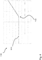
- Fig. 4 shows schematically and by way of example a diagram 1100 of a curve 1110 of the base value of the spread on the vertical axis over the flow temperature on the horizontal axis.
- the spread shows a constant course up to a threshold value 1120 and then increases as the flow temperature rises.
- the relationship can be linear or exponential or according to another function.
Landscapes
- Engineering & Computer Science (AREA)
- Physics & Mathematics (AREA)
- Mechanical Engineering (AREA)
- Thermal Sciences (AREA)
- General Engineering & Computer Science (AREA)
- Heat-Pump Type And Storage Water Heaters (AREA)
- Compression-Type Refrigeration Machines With Reversible Cycles (AREA)
Abstract
Description
- Die Erfindung betrifft ein Verfahren zum Betrieb einer Kompressionskälteanlage sowie eine zugehörige Kompressionskälteanlage mit einem Kältemittel, einem Verdampfer, einem Verdichter, einem Verflüssiger, einem Drosselorgan, einem internen Wärmeübertrager zur Übertragung von Wärmeenergie des Kältemittels vor Eintritt in das Drosselorgan an das Kältemittel vor Eintritt in den Verdichter, und einer Steuereinheit zur Erfassung einer Überhitzung des Kältemittels bei Eintritt in den Verdichter, wobei die Überhitzung als eine Differenz einer Taupunkttemperatur zu einer Temperatur des Kältemittels definiert ist, und einer Regelung des Drosselorgans basierend auf der Überhitzung.
- Derartige Kompressionskälteanlagen, beispielsweise in Form von Wärmepumpen, mit einem Dampfkompressionssystem in welchem ein gasförmiges Kältemittel von einem mittels der Steuereinheit, die beispielsweise einen Regler aufweist, gesteuerten Verdichter von einem Niederdruck auf einen Hochdruck verdichtet wird, sind bekannt.
- Das Kältemittel wird durch den Verflüssiger getrieben, in dem es eine Heizwärme an ein in einem Wärmesenkensystem befindliches Heizmedium abgibt. Eine innere Wärme wird in einem inneren Wärmeübertrager, beispielsweise in Form eines Rekuperators, zwischen dem unter dem Hochdruck vom Verflüssiger zum Expansionsventil strömenden Kältemittel und dem vom Verdampfer zum Verdichter unter dem Niederdruck strömende Kältemittel übertragen.
- Das Kältemittel wird weiter in einer Hochdruckströmungsrichtung zu einem vom Regler gesteuerten Expansionsventil geführt, in dem das Kältemittel vom Hochdruck auf den Niederdruck abhängig von einem Regelwert entspannt wird. Das auf dem Niederdruck befindliche Kältemittel verdampft in dem Verdampfer bei Aufnahme von Quellwärme.
- Aus
DE 101 59 892 A1 ist bei einer Kältemaschine bekannt, insbesondere bei einer Wärmepumpe, einen Rekuperator zu verwenden, womit bei niedrigen Außentemperaturen die Heizleistung auf baulich einfache Weise erhöht werden soll. Hierfür ist der Rekuperator derart dimensioniert, dass er bei niedrigen Verdampfungstemperaturen wenigstens etwa 15% der Heizleistung der Wärmepumpe vom flüssigen Kältemittel auf das gasförmige Kältemittel überträgt. Ein Einspritzventil spritzt flüssiges Kältemittel in den Verdichter, so dass die Verdichtungsendtemperatur unter 120 °C bleibt. - Eine Wärmepumpenanlage mit einem Kältemittelkreislauf ist aus
DE 10 2005 061 480 B3 bekannt. Sie ist mit einem Verdichter, einem ersten Wärmeübertrager, einem Drosselorgan, einem Verdampfer und einer 4-2-Wegeventileinheit zum Umschalten zwischen einer ersten (Heizen) und einer zweiten Betriebsart (Kühlen) ausgestattet. Eine Strömungsrichtung des in dem Kältemittelkreislauf befindlichen Kältemittels kann derart umgeschaltet werden kann, dass der erste Wärmeübertrager in der ersten Betriebsart zum Verflüssigen des Kältemittels, und in der zweiten Betriebsart zum Verdampfen des Kältemittels dient, und der zweite Wärmeübertrager in der ersten Betriebsart zum Verdampfen des Kältemittels und in der zweiten Betriebsart zum Verflüssigen des Kältemittels dient, wobei der erste Wärmeübertrager im Kältemittelkreislauf so verschaltet ist, dass er in den beiden Betriebsarten Heizen und Kühlen als Gegenstrom-Wärmeübertrager arbeitet. - Es ist bekannt, dass die Erreichung einer bestimmten Wärmesenkentemperatur, beispielsweise einer Vorlauftemperatur oder einer Rücklauftemperatur für einen Heizkreis, in etwa mit einem Druck des Kältemittels, das sich im Verflüssiger einstellt, korrespondiert. Abhängig von der Ausgestaltung des Kältekreises korrespondiert dieser auch Hochdruck genannte Druck des Kältemittels eher mit der Wärmesenken-Rücklauftemperatur oder der Wärmesenken-Vorlauftemperatur, abhängig beispielsweise von einer Unterkühlung des Kältemittels in einem internen Wärmeübertrager wie einem Rekuperator. Der Hochdruck muss während des Betriebs der Kompressionskälteanlage allerdings innerhalb der zulässigen Grenzen liegen.
- Aufgabe der Erfindung ist es, ein Regelverfahren für die eingangs genannte Kompressionskälteanlage vorzuschlagen, das einen optimierten Betrieb bei gleichzeitiger Einhaltung der Hochdruckgrenzen der Kompressionskälteanlage zu ermöglichen.
- Gelöst wir die Aufgabe durch die Verfahrensmerkmale des Anspruchs 1 sowie die Vorrichtungsmerkmale des Anspruchs 7.
- Demnach wird gemäß einem ersten Aspekt ein Verfahren zum Regeln einer Kompressionskälteanlage mit einem Kältekreis mit einem Kältemittel, einem Verdampfer, einem Verdichter, einem Verflüssiger, einem Drosselorgan, einem internen Wärmeübertrager zur Übertragung von Wärmeenergie des Kältemittels vor Eintritt in das Drosselorgan an das Kältemittel vor Eintritt in den Verdichter, einem Wärmesenkenkreis, der zum Wärmeübertrag mit dem Verflüssiger des Kältekreises ausgebildet ist, einer wärmesenkenseitigen Medienfördereinrichtung und einer Steuereinheit zur Regelung einer Temperaturdifferenz zwischen einer Vorlauftemperatur und einer Rücklauftemperatur des Wärmesenkenkreises, genannt Temperaturspreizung, mittels der Medienfördereinrichtung, vorgeschlagen. Das Verfahren umfasst die folgenden Schritte: a) Bilden eines Sockelwertes für die Temperaturspreizung, wobei der Sockelwert eine Effizienz des Kältekreises gewährleistet, b) Bilden wenigstens eines Korrekturwertes, wobei der oder die Korrekturwerte den Betrieb des Kältekreises in einem zulässigen Betriebsbereich gewährleisten, c) Addition des Sockelwertes und des oder der Korrekturwerte, um einen Sollwert für die Temperaturspreizung zu erhalten und d) Regeln der Medienfördereinrichtung auf den Sollwert für die Temperaturspreizung.
- Der Wärmesenkenkreis ist demnach in diesem Sinne zur Wärmeübertragung zwischen einem primären Wärmeträgermedium, beispielsweise ein Heizkreismedium mit Rücklauftemperatur und Vorlauftemperatur, und einem sekundären Wärmeträgermedium, beispielsweise eine Raumluft im Heizbetrieb, Warmwasser im Warmwasserladebetrieb, mittels eines Wärmeübertragers, beispielsweise eine Fußbodenheizung, ein Radiator etc. im Heizbetrieb und ein Warmwasserladewärmeübertrager im Warmwasserladebetrieb ausgebildet.
- Der Schritt des Bildens wenigstens eines Korrekturwertes umfasst vorzugsweise: e) Bestimmen eines Druckes des Kältemittel in einem Hochdruckabschnitt des Kältekreises, genannt Hochdruck, f) Bestimmen eines maximal zulässigen Hochdruckes im aktuellen Arbeitspunkt der Kompressionskälteanlage, g) Bestimmen des Korrekturwertes in Abhängigkeit eines Abstandes des Hochdruckes von dem maximal zulässigen Hochdruck.
- Vorzugsweise können zwei unterschiedliche Verfahren zur Steuerung bzw. Regelung eines Betriebes eines Kältekreises unterhalb des für den jeweiligen Betriebspunkt des Kältekreises geltenden Hochdruckgrenzwertes getrennt oder überlagert angewandt werden:
- Verfahren 1: Das steuernde Verfahren, welches sich nicht an dem im aktuellen Betriebspunkt gemessenen und an dem für den aktuellen Betriebspunkt geltenden Hochdruckgrenzwert orientiert: Als Funktion einer Wärmesenkentemperatur, beispielsweise einer Rücklauftemperatur, einer Vorlauftemperatur oder einer gewichteten Kombination von Anteilen der Temperaturen, insbesondere als Funktion der Vorlauftemperatur, wird der Korrekturwert zur Erhöhung des Sollwertes der Temperaturspreizung so ausgelegt, dass erwartet werden kann, durch die einhergehende Temperaturspreizungserhöhung und die damit gekoppelte Hochdruckabsenkung, insbesondere bezogen auf eine vergleichbare Mitteltemperatur des Wärmesenken-Systems, den Hochdruckgrenzwert einhalten zu können.
- Verfahren 2: Das regelnde Verfahren, welches sich insbesondere an dem im aktuellen Betriebspunkt gemessenen und an dem für den aktuellen Betriebspunkt geltenden Hochdruckgrenzwert orientiert: Als Funktion der Differenz zwischen aktuell erfasstem Hochdruck und dem für den jeweiligen Arbeitspunkt des Kältekreises geltenden Hochdruckgrenzwert, wird der Korrekturwert zur Erhöhung des Sollwertes der Temperaturspreizung so ausgelegt, dass erwartet werden kann, durch die einhergehende Temperaturspreizungserhöhung und die damit gekoppelte Hochdruckabsenkung, insbesondere bezogen auf eine vergleichbare Mitteltemperatur des Wärmesenken-Systems, den Hochdruckgrenzwert einhalten zu können.
- In Abhängigkeit der Kondensationsvorgänge des Kältemittels in dem Verflüssiger stellt sich ein Kondensationsdruck des Kältemittels ein, genannt Hochdruck. Der Hochdruck liegt im Wesentlichen in dem gesamten Bereich des Kältekreises zwischen Verdichter und Drosselorgan, z.B. Expansionsventil, an.
- Für jeden Kältekreis gibt es arbeitspunktabhängig, insbesondere abhängig von einer Drehzahl des Verdichters, einen maximal zulässigen Hochdruck, der üblicherweise vom Hersteller des Verdichters vorgegeben wird und nicht überschritten werden darf. Dieser kann beispielsweise in Form von Tabellen oder Funktionen in der Steuerung der Kompressionskälteanlage hinterlegt sein, wobei zwischen tabellierten Stützstellen vorzugsweise interpoliert wird. Die Überwachung des Hochdruckes ist vorgeschrieben.
- In Kältekreisen mit innerem Wärmeübertrager findet in dem Verflüssiger möglichst keine Unterkühlung statt. Auch eine negative Unterkühlung, das heißt dass die Verflüssigung im Verflüssiger nicht abgeschlossen wird, ist unerwünscht, da dies mit Leistungseinbußen verbunden ist.
- Erfindungsgemäß wurde erkannt, dass zu einer bestimmten Wärmesenkentemperatur ein Verflüssigungsdruck korrespondiert. In Abhängigkeit des Kältekreises und/oder des verwendeten Kältemittels korrespondiert der Verflüssigungsdruck, d.h. der Hochdruck, eher mit der Vorlauftemperatur oder mit der Rücklauftemperatur des Wärmesenkenmediums.
- Besonders bei Kompressionskälteanlagen, die wie erfindungsgemäße einen internen Wärmeübertrager enthalten, korrespondiert der Verflüssigungsdruck eher mit dem Rücklauf. Erfindungsgemäß wurde festgestellt, dass in diesem Fall durch eine Spreizsteuerung, also eine Steuerung, mit welcher die Temperaturdifferenz zwischen Vorlauf und Rücklauf des wärmesenkenseitigen Mediums gesteuert wird, der Betrieb des Kältekreises verbessert werden kann.
- Wird im Betrieb eine Annäherung des Hochdruckes an den zulässigen maximalen Hochdruck-Grenzwert detektiert, kann dadurch, dass in den erfindungsgemäßen Kältekreisen der Hochdruck mit der Rücklauftemperatur des wärmesenkenseitigen Mediums korreliert, der Hochdruck durch eine Verringerung der Rücklauftemperatur ebenfalls reduziert werden. Dadurch kann ein Erreichen oder sogar Überschreiten des maximal zulässigen Hochdruckes vermieden werden.
- Für die Wärmeübertragung ist die Mitteltemperatur zwischen Vorlauftemperatur und Rücklauftemperatur für üblicherweise im Gegenstrom durchströmte Verflüssiger ausschlaggebend.
- Um eine in etwa gleiche Wärmeübertragung im wärmesenkenseitigen Wärmeübertrager (Fußbodenheizsystem, Radiatorheizsystem, Luftheizregister, Wärmeübertrager für die Energieübertragung in einen Warmwasserspeicher) zu erreichen, kann daher beispielsweise die Vorlauftemperatur angehoben und die Rücklauftemperatur abgesenkt werden. Dies ist beispielsweise dadurch möglich, dass eine Pumpe im Kreis des Wärmesenkenmediums weniger Volumenstrom fördert. Analog führt eine Erhöhung des geförderten Volumenstroms durch die wärmesenkenseitige Medienfördereinrichtung zu einer niedrigeren Spreizung und damit einem Anstieg des Hochdrucks.
- Der Wert, auf den die Spreizung des Wärmesenkenkreises eingeregelt wird, erfolgt zunächst per Sockelwert auf einen üblichen Wert, der beispielsweise für Wärmepumpen als Kompressionskälteanlagen als 4-10K optimiert eingestellt wird.
- Hierzu werden die erfindungsgemäßen Korrekturwerte addiert, die dann eine Berücksichtigung des Arbeitspunktes der Kompressionskälteanlage und insbesondere die Betriebsgrenzen des Verdichters hochdruckseitig optimal berücksichtigen.
- Für Kältekreise ohne internen Wärmeübertrager wird die Befüllung mit Kältemittel häufig so ausgelegt, dass eine Unterkühlung im Verflüssiger selbst stattfindet, das heißt, dass die Siedetemperatur um den Unterkühlungstemperaturbetrag höher als die Kältemittelaustrittstemperatur liegt. Eine Unterkühlung des aus dem Verflüssiger austretenden Kältemittels bedeutet, dass das Kältemittel bezogen auf die Verflüssigungstemperatur (Siedetemperatur) durch Wärmekopplung mit Wärmesenkenmedientemperaturen, deren Temperatur unterhalb der Siedetemperatur des Kältemittels ist, unterhalb der Siedetemperatur abgekühlt wird. Das Kältemittel kondensiert dann mehrere Kelvin (K) über der Rücklauftemperatur, was bei üblichen Temperaturspreizungen von 4-10K bereits im Bereich der Vorlauftemperatur liegt.
- Vorzugsweise wird der Sockelwert empirisch durch Betrieb der Kompressionskälteanlage an wenigstens einem Normbetriebspunkt gebildet, wobei während des Betriebes an dem Normbetriebspunkt eine Variation der Temperaturspreizung durchgeführt wird.
- Zur Festlegung eines Temperaturspreizungs - Sockelwertes wird vorzugsweise für Betriebspunkte mit genügendem Abstand zum Hochdruckgrezwert wie folgt vorgegangen:
Die Kompressionskälteanlage in verschieden Arbeitspunkten mit nacheinander mit variierter Temperaturspreizung betrieben und auslegungsrelevanten Kenngrößen (KK - Wirkungsgrad, Reglerstabilität Temperaturdifferenzegier, Erfassungsgenauigkeit des Volumenstromsensors (relevant für die Wärmemengenmessung) , Volumenstrom (minimaler Grenzwert gewährleistet Durchströmung verteilter Heizkreise) durchgeführt und dann ein geeigneter Sockelwert als Kompromiss unter gewichteter Einbeziehung o.g. Kriterien festgelegt. Hierbei werden insbesondere die Erfüllung der Kriterien für Betriebspunkte, in welchen die WP voraussichtlich häufiger betrieben wird, stärker gewichtet als für Betriebspunkte, in welchen die WP voraussichtlich seltener betrieben wird. - Die Elektronik kann dann die vorgegebene, variierende Spreizung ausregeln und auf Basis des Verhaltens des Kältekreises bspw. von Regelschwingungen, auf einen geeigneten Sockelwert schließen, wie oben beschrieben.
- Vorzugsweise wird der Sockelwert alternativ oder zusätzlich modellbasiert abgeleitet, wobei für die Ableitung des modellbasierten Sockelwertes insbesondere eine finite Elemente Simulation zum Erhalt von Abhängigkeiten anhand von Messdaten angewandt wird.
- In dieser Form wird die Physik anhand von Messdaten abgebildet und Abhängigkeiten, Reglerstabilitäten etc. basierend darauf erhalten.
- Vorzugsweise ist der Sollwert für die Temperaturspreizung bis zu einem Schwellwert der Vorlauftemperatur des Wärmesenkenkreises konstant und entspricht insbesondere dem Sockelwert.
- Vorzugsweise steigt der Sollwert für die Temperaturspreizung über dem Schwellwert der Vorlauftemperatur als Funktion der Vorlauftemperatur an. Hiermit wird berücksichtigt, dass hohe Vorlauftemperaturen höhere Spreizungen erfordern, die für niedrigere Vorlauftemperaturen, beispielsweise unterhalb von 60°C, nicht erforderlich sind.
- Vorzugsweise enthalten die Korrekturwerte ferner wenigstens einen der folgenden Korrekturwerte:
- Korrekturwert zur modellbasierten Einhaltung einer oberen Vorlauftemperatur-Betriebsgrenze, welcher unterhalb einer Grenz-Vorlauftemperatur den Wert = 0 hat und oberhalb der Grenz-Vorlauftemperatur proportional zur Differenz zu der Grenz-Vorlauftemperatur im Wert ansteigt;
- Korrekturwert zur modellbasierten Einhaltung einer unteren Vorlauftemperatur-Betriebsgrenze, welcher oberhalb einer weiteren Grenz-Vorlauftemperatur den Wert = 0 hat und unterhalb der weiteren Grenz-Vorlauftemperatur proportional zur Differenz zu der weiteren Grenz-Vorlauftemperatur im Wert ins Negative absinkt;
- Korrekturwert, welcher mit Hilfe des Sockelwertes für den Sollwert der Temperaturdifferenz des Wärmesenkenmediums multipliziert mit einem Steuerfaktor eines Arbeitsbereichsreglers gebildet wird;
- Korrekturwert, welcher nach Berechnung nach einem oder beider der oben genannten Abhängigkeiten auf einen minimalen und / oder maximalen Grenzwert begrenzt wird.
- Ein insbesondere nach dem letzten Aspekt beschriebenes Verfahren kann verwendet werden, wenn ab einer bestimmten Vorlauftemperatur von beispielsweise 60°C ein proportional zu Vorlauftemperatur steigender Korrekturwert berechnet werden soll, der Maximalwert des Korrekturwertes aber auf 5 K begrenzt sein soll, um nicht so große Temperaturdifferenz-Sollwerte zu erhalten, bei welcher die Temperaturdifferenzregelung zu Regelschwingungen neigt oder der Volumenstrom so stark reduziert wird, dass der Volumenstromsensor kein Messignal mehr liefert.
- Vorzugsweise regelt die Steuerung den Kältekreis derart, dass das Kältemittel bei Austritt aus dem Verflüssiger eine Unterkühlung kleiner 3K, vorzugsweise kleiner 2K und besonders bevorzugt kleiner 1K aufweist.
- Im Idealfall hat das Kältemittel bei Austritt aus dem Verflüssiger keine Unterkühlung, aber ist vollständig verflüssigt. Damit wird ein optimaler Wirkungsgrad erreicht.
- Die Aufgabe wird erfindungsgemäß ferner durch eine Kompressionskälteanlage mit einem Kältekreis mit einem Kältemittel, einem Verdampfer, einem Verdichter, einem Verflüssiger, einem Drosselorgan, einem internen Wärmeübertrager zur Übertragung von Wärmeenergie des Kältemittels vor Eintritt in das Drosselorgan an das Kältemittel vor Eintritt in den Verdichter, einem Wärmesenkenkreis, der zum Wärmeübertrag mit dem Verflüssiger des Kältekreises ausgebildet ist, einer wärmesenkenseitigen Medienfördereinrichtung und einer Steuereinheit zur Regelung einer Temperaturdifferenz zwischen einer Vorlauftemperatur und einer Rücklauftemperatur des Wärmesenkenkreises, genannt Temperaturspreizung, mittels der Medienfördereinrichtung, gelöst.
- Die Steuereinheit ist ausgebildet zum: a) Bilden eines Sockelwertes für die Temperaturspreizung, wobei der Sockelwert eine Effizienz des Kältekreises gewährleistet, b) Bilden wenigstens eines Korrekturwertes, wobei der oder die Korrekturwerte den Betrieb des Kältekreises in einem zulässigen Betriebsbereich gewährleisten, c) Addition des Sockelwertes und des oder der Korrekturwerte zu einem Sollwert für die Temperaturspreizung und d) Regeln der Medienfördereinrichtung auf den Sollwert für die Temperaturspreizung.
- Die Steuereinheit ist ferner ausgebildet, für das Bilden wenigstens eines Korrekturwertes, die folgenden Schritte auszuführen: e) Bestimmen eines Druckes des Kältemittel in einem Hochdruckabschnitt des Kältekreises, genannt Hochdruck, f) Bestimmen eines maximal zulässigen Hochdruckes im aktuellen Arbeitspunkt der Kompressionskälteanlage, g) Bestimmen des Korrekturwertes in Abhängigkeit eines Abstandes des Hochdruckes von dem maximal zulässigen Hochdruck.
- Vorzugsweise weist das Kältemittel einen Temperaturglide auf, wobei als Kältemittel eine Mischung enthaltend R32 und R1234yf, insbesondere R454C, verwendet wird.
- Die Aufgabe wird ferner durch eine Wärmepumpe mit einer erfindungsgemäßen Kompressionskälteanlage gelöst.
- Weitere Vorteile und besondere Ausgestaltungen werden nachfolgend mit Verweis auf die beigefügten Figuren beschrieben.
- Die Figuren zeigen ein Ausführungsbeispiel:
- Fig. 1
- Wärmepumpe 100 mit einem Dampfkompressionskreislauf 200
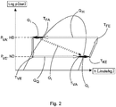
- Fig. 2
- log p / h - Diagramm des Dampfkompressionsprozesses mit Rekuperator 250
- Fig. 3
- zeigt schematisch und exemplarisch ein Flussdiagramm eines Verfahrens.
- Fig. 4
- zeigt schematisch und exemplarisch ein Diagramm eines Verlaufs des Sockelwertes der Spreizung
-
Fig. 1 zeigt schematisch und exemplarisch eine Wärmepumpe 100. Die Wärmepumpe 100 besteht im Wesentlichen aus einem eine Kompressionskälteanlage bildenden Dampfkompressionssystem 200, welches folgende Komponenten enthält: - Einen Verdichter 210 zum Verdichten des überhitzten Kältemittels,
- einen Verflüssiger 220, mit einem kältemittelseitigem Verflüssigereintritt 221 und einem Verflüssigeraustritt 222 zur Übertragung von Wärmeenergie QH aus dem Dampfkompressionssystem 200 an ein Heizmedium eines Heizsystems 400, mit einem Heizmediumeintritt 401, einem Heizmediumaustritt 402 und einer Heizmediumpumpe 410, zu einer Gebäudeheizung oder ein System zur Warmwassererhitzung,
- vorteilhaft einen Kältemittelsammler 260, welcher als Kältemittelreservoir zum Ausgleich von betriebsbedingungsabhängig unterschiedlich hohen Kältemittelmengenbedarfen verwendet wird,
- ein als Expansionsventil ausgebildetes Drosselorgan 230 zum Expandieren des Kältemittels,
- einen Verdampfer 240, mit einem Verdampfereinlass 241, zur Übertragung von Quellenenergie QQ aus einem Wärmequellensystem 300, mit einem Wärmequelleinlass 320 und einem Wärmequellauslass 310, wobei das Wärmequellsystem 300 insbesondere ein Solesystem sein kann, welches Wärmeenergie QQ aus dem Erdreich aufnimmt oder ein Luftsystem, welches Wärmeenergie QQ aus der Umgebungsluft aufnimmt und an das Dampfkompressionssystem 200 abgibt oder eine beliebige andere Wärmequelle,
- einen Rekuperator als Beispiel eines internen Wärmeübertragers 250, welcher dazu bestimmt ist, innere Wärmeenergie Qi zwischen dem vom Verflüssiger 220 zum Expansionsventil 230 strömenden Kältemittel auf das vom Verdampfer 240 zum Verdichter 210 strömende Kältemittel zu übertragen und
- ein Kältemittel, insbesondere ein Kältemittelgemisch aus wenigsten zwei Stoffen oder zwei Kältemitteln welches in einer Strömungsrichtung SHD und SND durch den Dampfkompressionskreis 200 strömt, wobei im Dampfkompressionskreislauf 200 Kältemitteldampf durch den Verdichter 210 auf einen Hochdruck HD gebracht wird und zu einem Verflüssiger 220 geführt ist, wobei ein Hochdruckpfad mit der Hochdruckströmungsrichtung SHD vom Verdichter 210 bis zum Expansionsventil 230 gebildet ist. Nach dem Expansionsventil 230 bis zum Verdichter 210 ist ein Niederdruckpfad mit einer Niederdruckströmungsrichtung SND des Kältemittels gebildet, in dem der Verdampfer 240 liegt.
- In dem in
Fig. 1 gezeigten Beispiel ist die Wärmepumpe 100 als Sole-Wärmepumpe gezeigt. Natürlich sind analoge Betrachtungen und Vorteile mit Luft-/Wasser-Wärmepumpen erreichbar. Insbesondere bei Luft-Wärmepumpen ist anstelle des Solekreises mit Solepumpe 330 ein Ventilator/Lüfter als Wärmequelle angeordnet. - Der Verdichter 210 dient zur Kompression des überhitzten Kältemittels von einem Eintrittsanschluss 211 auf einen Verdichteraustrittsdruck PVa bei einer Verdichteraustrittstemperatur entsprechend der Heißgastemperatur am Verdichteraustritt 212. Der Verdichter 210 enthält üblicher Weise eine Antriebseinheit mit einem Elektromotor, eine Kompressionseinheit und vorteilhaft kann der Elektromotor drehzahlvariabel betrieben werden. Die Kompressionseinheit kann als Rollkolbeneinheit, Scrolleinheit oder anders ausgeführt sein. Am Verdichteraustritt 212 ist das komprimierte überhitzte Kältemittel beim Verdichteraustrittsdruck PVa auf einer höheren Drucklage, insbesondere einem Hochdruck HD, als am Eintrittsanschluss 211 mit einem Verdichtereintrittsdruck PVe, insbesondere einem Niederdruck ND, bei einer Verdichter Eintrittstemperatur TVE, was den Zustand der Kältemitteltemperatur am Eintrittsanschluss 211 bei Eintritt in eine Kompressionskammer beschreibt.
- Im Verflüssiger 220 erfolgt die Übertragung von Wärmeenergie QH vom Kältemittel des Dampfkompressionssystem 200 an ein Heizmedium des Wärmesenkensystems 400. Zunächst findet im Verflüssigter 220 die Enthitzung des Kältemittels statt, wobei überhitzter Kältemitteldampf durch eine Temperaturreduzierung einen Teil seiner Wärmeenergie an das Heizmedium des Wärmesenkensystems 400 überträgt.
- Nach der Enthitzung des Kältemitteldampfes erfolgt vorteilhaft im Verflüssiger 220 eine weitere Wärmeübertragung QH durch Kondensation des Kältemittels beim Phasenübergang von der Gasphase des Kältemittels auf die Flüssigphase des Kältemittels. Dabei wird weitere Wärme QH vom Kältemittel aus dem Dampfkompressionssystem 200 an das Heizmedium des Wärmesenkensystems 400 übertragen.
- Der sich im Verflüssiger 220 einstellende Hochdruck HD des Kältemittels korrespondiert im Betrieb des Verdichters 210 in etwa mit einem Kondensationsdruck des Kältemittels bei einer Heizmediumtemperatur Tws im Wärmesenkensystem.
- Das Heizmedium, insbesondere Wasser, wird mittels einer Heizmediumpumpe 410 durch das Wärmesenkensystem 400 in einer Richtung SW durch den Verflüssiger 220 gefördert, dabei wird die Wärmeenergie QH vom Kältemittel auf das Heizmedium übertragen.
- Im nachfolgenden Sammler 260 wird aus dem Verflüssiger 220 austretendes Kältemittel gespeichert, welches abhängig vom Betriebspunkt des Dampfkompressionskreises 200 nicht in das zirkulierende Kältemittel eingespeist werden soll. Wird aus dem Verflüssiger 220 mehr Kältemittel eingespeist, als durch das Expansionsventil 230 weitergeleitet wird, füllt sich der Sammler 260, anderenfalls wird er leerer oder entleert.
- Im nachfolgenden Rekuperator 250, der auch als interner Wärmeübertrager bezeichnet werden kann, wird interne Wärmeenergie Qi vom unter dem Hochdruck HD stehenden Kältemittel, welches vom Verflüssiger 220 zum Expansionsventil 230 in einer Hochdruck-Strömungsrichtung SHD strömt, auf das unter dem Niederdruck ND strömende Kältemittel übertragen, welches vom Verdampfer zum Verdichter in einer Niederdruckströmungsrichtung SND strömt, übertragen. Dabei wird das vom Verflüssiger zum Expansionsventil 230 strömende Kältemittel in vorteilhafter Weise unterkühlt.
- Zunächst strömt das Kältemittel durch einen Expansionsventileintritt 231 in das Expansionsventil ein. Im Expansionsventil 230 erfolgt eine Drosselung des Kältemitteldruckes vom Hochdruck HD auf den Niederdruck ND, indem das Kältemittel vorteilhaft eine Düsenanordnung oder Drossel mit einem vorteilhaft variablen Öffnungsquerschnitt passiert, wobei der Niederdruck vorteilhaft in etwa ein Saugdruck des Verdichters 210 entspricht. Anstelle eines Expansionsventils 230 kann auch eine andere beliebige Druckminderungseinrichtung eingesetzt sein. Vorteilhaft sind Druckminderungsrohre, Turbinen oder andere Entspannungsvorrichtungen.
- Ein Öffnungsgrad des Expansionsventils 230 wird durch einen Elektromotor, der üblicherweise als Schrittmotor ausgeführt ist eingestellt, welcher durch die Steuereinheit oder Regelung 500 gesteuert wird. Dabei wird der Niederdruck ND beim Expansionsventilaustritt 232 des Kältemittels aus dem Expansionsventil 230 so gesteuert, dass der sich einstellende Niederdruck ND des Kältemittels im Betrieb des Verdichters 210 in etwa mit dem Verdampfungsdruck des Kältemittels mit der Wärmequellenmedientemperatur TWQ korrespondiert. Vorteilhaft wird die Verdampfungstemperatur des Kältemittels wenige Kelvin unterhalb der Wärmequellen-Medientemperatur TWQ liegen, damit die Temperaturdifferenz eine Wärmeübertragung treibt.
- Im Verdampfer erfolgt eine Übertragung von Verdampfungswärmeenergie Qv vom Wärmequellenfluid des Wärmequellensystems 300, welches ein Solesystem, ein Erdwärmesystem zur Nutzung von Wärmeenergie QQ aus dem Erdreich, ein Luftsystem zur Nutzung von Energie QQ aus der Umgebungsluft oder eine andere Wärmequelle sein, die die Quellenergie QQ an das Dampfkompressionssystem 200 abgibt.
- Das in den Verdampfer 240 einströmende Kältemittel reduziert beim Durchströmen des Verdampfers 240 durch Wärmeaufnahme QQ seinen Nassdampfanteil und verlässt den Verdampfer 240 vorteilhaft mit einem geringen Nassdampfanteil oder vorteilhaft auch als überhitztes gasförmiges Kältemittel. Das Wärmequellenmedium wird mittels einer Solepumpe 330 bei Sole - Wasser-Wärmepumpen oder einem Außenluftventilator bei Luft/Wasser-Wärmepumpen durch den Wärmequellenmedienpfad des Verdampfers 240 gefördert, wobei beim Durchströmen des Verdampfers dem Wärmequellenmedium die Wärmeenergie QQ entzogen wird.
- Im Rekuperator 250 wird Wärmeenergie Qi zwischen dem vom Verflüssiger 220 zum Expansionsventil 230 strömenden Kältemittel auf das vom Verdampfer 240 zum Verdichter 210 strömende Kältemittel übertragen, wobei das vom Verdampfer 240 zum Verdichter 210 strömende Kältemittel insbesondere weiter überhitzt.
- Dieses überhitzte Kältemittel, welches mit einer Überhitzungstemperatur TKe aus dem Rekuperator 250 austritt, wird zum Kältemitteleintrittsanschluss 211 des Verdichters 210 geleitet.
- Der Rekuperator 250 ist im Dampfkompressionskreis 200 eingesetzt, um den Gesamt - Wirkungsgrad als Quotient aus abgegebener Heizleistung QH und aufgenommener elektrischer Leistung Pe zum Antrieb des Verdichtermotors zu erhöhen.
- Zu diesem Zweck wird dem Kältemittel, welches im Verflüssiger 220 Wärmeenergie QH auf einem wärmesenkenseitigen Temperaturniveau an das Heizmedium abgibt, im Hochdruckpfad des Rekuperators 250 durch Unterkühlung weitere Wärmeenergie Qi entzogen.
- Der innere Energiezustand des Kältemittels beim Eintritt in den Verdampfer 240 ist durch diesen Wärmeentzug Qi reduziert, sodass das Kältemittel bei gleichem Verdampfungstemperaturniveau mehr Wärmeenergie QQ aus der Wärmequelle 300 aufnehmen kann.
- Anschließend wird dem Kältemittel, nach dem Verdampferaustritt 242 aus dem Verdampfer 240, im Niederdruckpfad bei Niederdruck ND und bei einer Niederdrucktemperatur entsprechend einer Verdampferaustrittstemperatur TVa am Eintritt in den Rekuperator 250 die im Hochdruckpfad entzogene Wärmeenergie Qi wieder zugeführt. Die Zuführung der Energie bewirkt vorteilhat eine Reduzierung des Nassdampfanteils auf einen Zustand ohne Nassdampfanteil. Die Überhitzung wird durch weitere Energiezuführung sichergestellt.
- Des Weiteren sind zur Erfassung des Betriebszustandes des Dampfkompressionssystems 200 vorteilhaft folgende Sensoren angeordnet, mit denen insbesondere zur Absicherung und Optimierung der Betriebsbedingungen des Dampfkompressionssystems 200 insbesondere bei Betriebszustandsänderungen eine modellbasierte Vorsteuerung umgesetzt ist.
- Einerseits erfolgt vorteilhaft mit Hilfe der durch Sensoren erfassten Prozesswerte eine Absicherungen bezüglich zulässiger Arbeitsbereiche der Komponenten wie insbesondere dem Verdichter 210, andererseits erfolgen basierend auf den Sensordaten modellbasierte Vorsteuerungen insbesondere einer Drehzahl des Verdichters 210 und/oder einem Ventilöffnungsgrad des Expansionsventils, so dass die Regler zur Ausregelung einer sich dennoch, durch die Vorsteuerung aber kleineren, Regelabweichung nur noch kleinere Korrekturen durchführen muss:
- Ein Hochdrucksensor 503 vorteilhaft zur Erfassung des Hochdrucks HD des Kältemittels am Verdichteraustritt 212 oder zwischen dem Verdichteraustritt 212 und dem Expansionsventileintritt 231,
- ein Heißgastemperatursensor 504 vorteilhaft zur Erfassung einer Heißgastemperatur THG des Kältemittels am Verdichteraustritt 212, oder im Kältekreisabschnitt zwischen dem Verdichteraustritt 212 und dem Verflüssigereintritt 221,
- ein Innentemperatursensor 506 vorteilhaft zur Erfassung der Innentemperatur Tle des Kältemittels zwischen dem hochdruckseitigem internen Rekuperatorauslass 252 des Kältemittels aus dem Rekuperator 250 und dem Expansionsventileitritt 231. Die Innentemperatur ist vorteilhaft auch als "Rekuperatoraustrittstemperatur Hochdruckpfad" benannt und
- vorteilhaft ein Rekuperatorinnentemperatursensor 505. Der Rekuperatorinnentemperatursensor 505 erfasst vorteilhaft Verflüssigeraustrittstemperatur TFA des Kältemittels in der Strömungsrichtung am Verflüssigeraustritt oder dem hochdruckseitigen Rekuperatoreintritt und daher wird vorteilhaft die Verflüssigeraustrittstemperatur TFA vom Rekuperatorinnentemperatursensor 505 gemessen.
- Ein Niederdrucksensor 502 zur Erfassung des Niederdrucks ND des Kältemittels am Verdichtereintritt 211, oder zwischen dem Expansionsventil 230 und dem Verdichtereintritt 211,
- ein Verdampferaustrittstemperatursensor 508 zur Erfassung der Verdampferaustrittstemperatur TVa des Kältemittels am Verdampferaustritt 242 oder zwischen dem Verdampferaustritt 242 und dem niederdruckseitigen Eintritt des Kältemittels in den Rekuperatoreinlass 251 des Rekuperators 250 und
- ein Niederdrucktemperatursensor 501 misst vorteilhaft eine Verdichtereintrittstemperatur oder dient vorteilhaft zur Erfassung der Kältemittelniederdrucktemperatur TND oder vorteilhaft einer Verdichtereintrittstemperatur TKE am Verdichtereintritt 211, oder zwischen dem niederdruckseitigem Rekuperatorauslass 252 des Kältemittels aus dem Rekuperator 250 und dem Verdichtereintritt 211.
- Die Überhitzung beschreibt die Temperaturdifferenz zwischen der erfassten Verdichtereintrittstemperatur TKE des Kältemittels und der Verdampfungstemperatur des Kältemittels bei gesättigtem Dampf.
- Erfindungsgemäß wird vorzugsweise die Verdichtereintrittsüberhitzung derart geregelt, dass kein Kondensat durch Taupunktunterschreitung des in der Umgebungsluft enthaltenden Wasserdampfanteils an Komponenten des Kältekreises insbesondere im Abschnitt zwischen Kältemittelaustritt des Rekuperators 252 und Verdichtereintritt 211 ausfällt. Der Kältekreisabschnitt zwischen Verdampferaustritt 242 und Rekuperatoreintritt 251 ist zwar üblicherweise kälter, weil dieser typischerweise nur ein kurzer Rohrabschnitt ist, ist eine bessere Isolierung im Vergleich zu dem Abschnitt zwischen Kältemittelaustritt des Rekuperators 252 und Verdichtereintritt 211 möglich. Beispielsweise sitzt an der Stelle des Verdichtereintritts 211 am Verdichter der Kältemittelabscheider, der geschützt werden soll. Dieser kann schlecht eingehaust werden, so dass hier die Temperatur so hochgehalten werden soll, dass nichts kondensiert. Die Problematik der Kondensation tritt auf der Hochdruckseite im Regelfall nicht auf. Auch die Passage zwischen hochdruckseitigem Rekuperatoraustritt 252 und Eintritt in das Expansionsventil 231 kühlt regelmäßig in Abhängigkeit des Betriebspunktes bei idealen Wärmeübertragungsbedingungen im Rekuperator 250 auf das Temperaturniveau des Kältemittels am Verdampferaustritt 242 ab. Da aber auch diese Passage typischerweise kurz ist und man kann sie sehr gut isolieren kann, ist auch dieser Abschnitt im Regelfall nicht problematisch. Es sollte jedoch beachtet werden, dass das erfindungsgemäße Verfahren einen Kondensatabfall grundsätzlich über den gesamten Kreislauf der Wärmepumpe verhindern kann.
- Erfindungsgemäß wird vorzugsweise die Verdichtereintrittsüberhitzung derart geregelt, dass kein Kondensat durch Taupunktunterschreitung des in der Umgebungsluft enthaltenden Wasserdampfanteils an Komponenten des Kältekreises insbesondere im Abschnitt zwischen Kältemittelaustritt des Rekuperators 252 und Verdichtereintritt 211 ausfällt. Der Kältekreisabschnitt zwischen Verdampferaustritt 242 und Rekuperatoreintritt 251 ist zwar üblicherweise kälter, weil dieser typischerweise nur ein kurzer Rohrabschnitt ist, ist eine bessere Isolierung im Vergleich zu dem Abschnitt zwischen Kältemittelaustritt des Rekuperators 252 und Verdichtereintritt 211 möglich. Beispielsweise sitzt an der Stelle des Verdichtereintritts 211 am Verdichter der Kältemittelabscheider, der geschützt werden soll. Dieser kann schlecht eingehaust werden, so dass hier die Temperatur so hochgehalten werden soll, dass nichts kondensiert. Die Problematik der Kondensation tritt auf der Hochdruckseite im Regelfall nicht auf. Auch die Passage zwischen hochdruckseitigem Rekuperatoraustritt 252 und Eintritt in das Expansionsventil 231 kühlt regelmäßig in Abhängigkeit des Betriebspunktes bei idealen Wärmeübertragungsbedingungen im Rekuperator 250 auf das Temperaturniveau des Kältemittels am Verdampferaustritt 242 ab. Da aber auch diese Passage typischerweise kurz ist und man kann sie sehr gut isolieren kann, ist auch dieser Abschnitt im Regelfall nicht problematisch. Es sollte jedoch beachtet werden, dass das erfindungsgemäße Verfahren einen Kondensatabfall grundsätzlich über den gesamten Kreislauf der Wärmepumpe verhindern kann.
- Wenn - zum Zwecke eines Zahlenbeispiels - ein Verdampfungstemperaturniveau von ca. -10°C angenommen wird und die Temperatur am Soleeintritt 330 bei etwa -10°C, am Soleaustritt 310 etwa -13°C und am Verdichtereintritt 5°C beträgt, beträft die Überhitzung 15K.
- Vorteilhaft sind bei vielen Anlagen Raumtemperatursensor und Raumfeuchtesensor, die eine genaue Bestimmung der Auskondensierungsbedingungen der Luft ermöglicht, bspw. liegt bei 21 °C und 60% rel. Feuchte die Kondensationstemperatur im Bereich von 13°C. Unter diesen Bedingungen findet also, so lange die Rohrtemperatur über 13°C zuzüglich gegebenenfalls einen Puffer, bspw. 1K, keine Kondensation statt.
-
Fig. 3 zeigt schematisch und exemplarisch ein Flussdiagramm eines Verfahrens 1000 zum Regeln einer Kompressionskälteanlage 200. - In einem Schritt 1010 wird ein Sockelwert für die Temperaturspreizung gebildet, wobei der Sockelwert eine Effizienz des Kältekreises gewährleistet.
- In einem Schritt 1020 wird wenigstens ein Korrekturwert gebildet, wobei der oder die Korrekturwerte den Betrieb des Kältekreises in einem zulässigen Betriebsbereich gewährleisten. Insbesondere umfasst der Schritt 1020 folgende Teilschritte:
- Einen Teilschritt 1022 des Bestimmens eines Druckes des Kältemittel in einem Hochdruckabschnitt des Kältekreises, genannt Hochdruck,
- Einen Teilschritt 1024 des Bestimmens eines maximal zulässigen Hochdruckes im aktuellen Arbeitspunkt der Kompressionskälteanlage,
- Einen Teilschritt 1026 des Bestimmens des Korrekturwertes in Abhängigkeit eines Abstandes des Hochdruckes von dem maximal zulässigen Hochdruck.
- Anschließend wird in einem Schritt 1030 der Sockelwert und der oder die Korrekturwerte zu einem Sollwert für die Temperaturspreizung addiert.
- Die Medienfördereinrichtung 410 wird dann in einem Schritt 1040 auf den Sollwert für die Temperaturspreizung geregelt.
-
Fig. 4 zeigt schematisch und exemplarisch ein Diagramm 1100 eines Verlaufs 1110 des Sockelwertes der Spreizung auf der vertikalen Achse über die Vorlauftemperatur auf der horizontalen Achse. Bis zu einem Schwellwert 1120 zeigt der Verlauf der Spreizung einen konstanten Verlauf und nimmt anschließend mit steigender Vorlauftemperatur zu. Der Zusammenhang kann wie dargestellt linear oder auch exponentiell oder gemäß einer anderen Funktion sein.
Claims (10)
- Verfahren zum Regeln einer Kompressionskälteanlage (200) mit- einem Kältekreis mit- einem Kältemittel,- einem Verdampfer (240),- einem Verdichter (210),- einem Verflüssiger (220),- einem Drosselorgan (230),- einem internen Wärmeübertrager (250) zur Übertragung von Wärmeenergie des Kältemittels vor Eintritt in das Drosselorgan (230) an das Kältemittel vor Eintritt in den Verdichter (210),- einem Wärmesenkenkreis (400), der zum Wärmeübertrag mit dem Verflüssiger (220) des Kältekreises ausgebildet ist,- einer wärmesenkenseitigen Medienfördereinrichtung (410) und- einer Steuereinheit (500) zur Regelung einer Temperaturdifferenz zwischen einer Vorlauftemperatur und einer Rücklauftemperatur des Wärmesenkenkreises (400), genannt Temperaturspreizung, mittels der Medienfördereinrichtung (410),wobei das Verfahren die folgenden Schritte umfasst:- Bilden (1010) eines Sockelwertes für die Temperaturspreizung, wobei der Sockelwert eine Effizienz des Kältekreises gewährleistet,- Bilden (1020) wenigstens eines Korrekturwertes, wobei der oder die Korrekturwerte den Betrieb des Kältekreises in einem zulässigen Betriebsbereich gewährleisten,- Addition (1030) des Sockelwertes und des oder der Korrekturwerte, um einen Sollwert für die Temperaturspreizung zu erhalten, und- Regeln (1040) der Medienfördereinrichtung (410) auf den Sollwert für die Temperaturspreizung.
- Verfahren nach Anspruch 1, wobei der Schritt des Bildens wenigstens eines Korrekturwertes umfasst:- Bestimmen (1022) eines Druckes des Kältemittel in einem Hochdruckabschnitt des Kältekreises, genannt Hochdruck,- Bestimmen (1024) eines maximal zulässigen Hochdruckes im aktuellen Arbeitspunkt der Kompressionskälteanlage,- Bestimmen (1026) des Korrekturwertes in Abhängigkeit eines Abstandes des Hochdruckes von dem maximal zulässigen Hochdruck.
- Verfahren nach einem der vorstehenden Ansprüche, wobei- der Sockelwert empirisch durch Betrieb der Kompressionskälteanlage an wenigstens einem Normbetriebspunkt gebildet wird, wobei während des Betriebes an dem Normbetriebspunkt eine Variation der Temperaturspreizung durchgeführt wird, und/oder- der Sockelwert modellbasiert abgeleitet wird, wobei für die Ableitung des modellbasierten Sockelwertes insbesondere eine finite Elemente Simulation zum Erhalt von Abhängigkeiten anhand von Messdaten angewandt wird.
- Verfahren nach einem der vorstehenden Ansprüche, wobei der Sollwert für die Temperaturspreizung bis zu einem Schwellwert der Vorlauftemperatur des Wärmesenkenkreises (400) konstant ist und insbesondere dem Sockelwert entspricht.
- Verfahren nach Anspruch 4, wobei der Sollwert für die Temperaturspreizung über dem Schwellwert der Vorlauftemperatur als Funktion der Vorlauftemperatur ansteigt.
- Verfahren nach einem der vorstehenden Ansprüche, wobei die Korrekturwerte ferner wenigstens einen der folgenden Korrekturwerte enthalten:- Korrekturwert zur modellbasierten Einhaltung einer oberen Vorlauftemperatur-Betriebsgrenze, welcher unterhalb einer Grenz-Vorlauftemperatur den Wert = 0 hat und oberhalb der Grenz-Vorlauftemperatur proportional zur Differenz zu der Grenz-Vorlauftemperatur im Wert ansteigt;- Korrekturwert zur modellbasierten Einhaltung einer unteren Vorlauftemperatur-Betriebsgrenze, welcher oberhalb einer weiteren Grenz-Vorlauftemperatur den Wert = 0 hat und unterhalb der weiteren Grenz-Vorlauftemperatur proportional zur Differenz zu der weiteren Grenz-Vorlauftemperatur im Wert ins Negative absinkt;- Korrekturwert , welcher nach Berechnung nach einem oder beider der oben genannten Abhängigkeiten auf einen minimalen und / oder maximalen Grenzwert begrenzt wird.- Korrekturwert, welcher mit Hilfe des Sockelwertes für den Sollwert der Temperaturdifferenz des Wärmesenkenmediums multipliziert mit einem Steuerfaktor eines Arbeitsbereichsreglers gebildet wird.
- Verfahren nach einem der vorstehenden Ansprüche, wobei die Steuerung den Kältekreis derart regelt, dass das Kältemittel bei Austritt aus dem Verflüssiger eine Unterkühlung kleiner 3K, vorzugsweise kleiner 2K und besonders bevorzugt kleiner 1K aufweist.
- Kompressionskälteanlage (200) mit- einem Kältekreis mit- einem Kältemittel,- einem Verdampfer (240),- einem Verdichter (210),- einem Verflüssiger (220),- einem Drosselorgan (230),- einem internen Wärmeübertrager (250) zur Übertragung von Wärmeenergie des Kältemittels vor Eintritt in das Drosselorgan (230) an das Kältemittel vor Eintritt in den Verdichter (210),- einem Wärmesenkenkreis (400), der zum Wärmeübertrag mit dem Verflüssiger (220) des Kältekreises ausgebildet ist,- einer wärmesenkenseitigen Medienfördereinrichtung (410) und- einer Steuereinheit (500) zur Regelung einer Temperaturdifferenz zwischen einer Vorlauftemperatur und einer Rücklauftemperatur des Wärmesenkenkreises (400), genannt Temperaturspreizung, mittels der Medienfördereinrichtung (410),wobei die Steuereinheit (500) ausgebildet ist zum:- Bilden eines Sockelwertes für die Temperaturspreizung, wobei der Sockelwert eine Effizienz des Kältekreises gewährleistet,- Bilden wenigstens eines Korrekturwertes, wobei der oder die Korrekturwerte den Betrieb des Kältekreises in einem zulässigen Betriebsbereich gewährleisten,- Addition des Sockelwertes und des oder der Korrekturwerte zu einem Sollwert für die Temperaturspreizung und- Regeln der Medienfördereinrichtung (410) auf den Sollwert für die Temperaturspreizung.
- Kompressionskälteanlage nach Anspruch 8, wobei das Kältemittel einen Temperaturglide aufweist, wobei als Kältemittel insbesondere R454C verwendet wird.
- Wärmepumpe (100), insbesondere im Inneren eines Gebäudes aufgestellte Wärmepumpe (100), mit einer Kompressionskälteanlage (200) gemäß Anspruch 8 oder 9.
Applications Claiming Priority (1)
| Application Number | Priority Date | Filing Date | Title |
|---|---|---|---|
| DE102020115269.8A DE102020115269A1 (de) | 2020-06-09 | 2020-06-09 | Verfahren zum Betrieb einer Kompressionskälteanlage und zugehörige Kompressionskälteanlage |
Publications (2)
| Publication Number | Publication Date |
|---|---|
| EP3922930A1 true EP3922930A1 (de) | 2021-12-15 |
| EP3922930B1 EP3922930B1 (de) | 2024-02-28 |
Family
ID=76269626
Family Applications (1)
| Application Number | Title | Priority Date | Filing Date |
|---|---|---|---|
| EP21177558.0A Active EP3922930B1 (de) | 2020-06-09 | 2021-06-03 | Verfahren zum betrieb einer kompressionskälteanlage und zugehörige kompressionskälteanlage |
Country Status (2)
| Country | Link |
|---|---|
| EP (1) | EP3922930B1 (de) |
| DE (1) | DE102020115269A1 (de) |
Citations (5)
| Publication number | Priority date | Publication date | Assignee | Title |
|---|---|---|---|---|
| DE10159892A1 (de) | 2001-12-06 | 2003-06-26 | Stiebel Eltron Gmbh & Co Kg | Kältemaschine mit einem Rekuperator |
| DE102005001231A1 (de) * | 2005-01-11 | 2006-07-13 | Daimlerchrysler Ag | Klimaanlage für Kraftfahrzeuge |
| DE102005061480B3 (de) | 2005-12-22 | 2007-04-05 | Stiebel Eltron Gmbh & Co. Kg | Wärmepumpenanlage |
| EP2375174A2 (de) * | 2010-04-07 | 2011-10-12 | Wolf GmbH | Wärmepumpenanlage und Verfahren zur Regelung einer Wärmepumpenanlage |
| WO2017072324A1 (en) * | 2015-10-30 | 2017-05-04 | Efficient Energy Gmbh | Heat pump and method for pumping heat by using a bypass mode and dual use of the temperature sensor signal |
Family Cites Families (6)
| Publication number | Priority date | Publication date | Assignee | Title |
|---|---|---|---|---|
| DE9415089U1 (de) | 1994-09-17 | 1996-02-01 | Robert Bosch Gmbh, 70469 Stuttgart | Zentralheizungsanlage |
| JP3737381B2 (ja) | 2000-06-05 | 2006-01-18 | 株式会社デンソー | 給湯装置 |
| WO2006024182A2 (de) | 2004-09-03 | 2006-03-09 | Felix Kalberer | Verfahren und anlage zur regelung eines carnot-kreislaufprozesses |
| JP5470374B2 (ja) | 2009-04-13 | 2014-04-16 | パナソニック株式会社 | ヒートポンプ式暖房装置 |
| JP5984784B2 (ja) | 2013-11-19 | 2016-09-06 | 三菱電機株式会社 | 温冷水空調システム |
| DE102018113687B4 (de) | 2018-06-08 | 2023-08-03 | Hanon Systems | Vorrichtung und Verfahren zur Kühlung von Batteriezellenmodulen |
-
2020
- 2020-06-09 DE DE102020115269.8A patent/DE102020115269A1/de active Pending
-
2021
- 2021-06-03 EP EP21177558.0A patent/EP3922930B1/de active Active
Patent Citations (5)
| Publication number | Priority date | Publication date | Assignee | Title |
|---|---|---|---|---|
| DE10159892A1 (de) | 2001-12-06 | 2003-06-26 | Stiebel Eltron Gmbh & Co Kg | Kältemaschine mit einem Rekuperator |
| DE102005001231A1 (de) * | 2005-01-11 | 2006-07-13 | Daimlerchrysler Ag | Klimaanlage für Kraftfahrzeuge |
| DE102005061480B3 (de) | 2005-12-22 | 2007-04-05 | Stiebel Eltron Gmbh & Co. Kg | Wärmepumpenanlage |
| EP2375174A2 (de) * | 2010-04-07 | 2011-10-12 | Wolf GmbH | Wärmepumpenanlage und Verfahren zur Regelung einer Wärmepumpenanlage |
| WO2017072324A1 (en) * | 2015-10-30 | 2017-05-04 | Efficient Energy Gmbh | Heat pump and method for pumping heat by using a bypass mode and dual use of the temperature sensor signal |
Also Published As
| Publication number | Publication date |
|---|---|
| DE102020115269A1 (de) | 2021-12-09 |
| EP3922930B1 (de) | 2024-02-28 |
Similar Documents
| Publication | Publication Date | Title |
|---|---|---|
| DE2545606C2 (de) | Verfahren zum Betrieb eines Kühlsystems sowie Kühlsystem zur Durchführung des Verfahrens | |
| EP3816543B1 (de) | Verfahren zur regelung eines expansionsventils | |
| DE102019201427B4 (de) | Verfahren zum Betreiben eines Kältemittelkreislaufs einer Kälteanlage eines Fahrzeugs | |
| EP3004754B1 (de) | Wärmepumpe zur verwendung von umweltverträglichen kältemitteln | |
| EP3730873B1 (de) | Verfahren zum betreiben einer wäremepumpe mit einem dampfkompressionssystem | |
| EP3922926B1 (de) | Verfahren zum regeln eines abtauvorgangs eines verdampfers einer kompressionskälteanlage und kompressionskälteanlage | |
| DE10159892A1 (de) | Kältemaschine mit einem Rekuperator | |
| EP3099985B1 (de) | Kälteanlage | |
| EP3922932B1 (de) | Verfahren zum betreiben einer kompressionskälteanlage und kompressionskälteanlage | |
| DE102012110237B4 (de) | Druckluft-Kältetrockner | |
| DE102020115270A1 (de) | Verfahren und Vorrichtung zum Regeln eines Kältekreislaufs | |
| EP3922931B1 (de) | Kompressionskälteanlage und verfahren zum betrieb selbiger | |
| DE102005052763A1 (de) | Wärmepumpen-Heizvorrichtung | |
| DE202007017723U1 (de) | Anlage für die Kälte-, Heiz- oder Klimatechnik, insbesondere Kälteanlage | |
| EP3922925B1 (de) | Verfahren zum betrieb einer kompressionskälteanlage und kompressionskälteanlage | |
| EP3922930B1 (de) | Verfahren zum betrieb einer kompressionskälteanlage und zugehörige kompressionskälteanlage | |
| EP3922929B1 (de) | Verfahren zum regeln einer kompressionskälteanlage und kompressionskälteanlage | |
| EP1570215B1 (de) | Verdampfungsprozesssteuerung in der kältetechnik | |
| EP3922924B1 (de) | Verfahren zum betrieb einer kompressionskälteanlage und kompressionskälteanlage | |
| DE112021007291T5 (de) | Wärmequellenmaschine einer Kühlvorrichtung und Kühlvorrichtung einschließlich derselben | |
| EP3922933B1 (de) | Verfahren zum regeln einer kompressionskälteanlage und kompressionskälteanlage | |
| DE10338388B3 (de) | Verfahren zur Regelung einer Klimaanlage | |
| DE102020115264A1 (de) | Verfahren zum Betrieb einer Kompressionskälteanlage und zugehörige Kompressionskälteanlage | |
| EP4579151A1 (de) | Verfahren und entsprechend ausgebildete vorrichtung zum regeln eines kältekreislaufs sowie kompressionskälteanlage | |
| DE102024209586A1 (de) | Kompressionskältemaschine und Verfahren zur Verdampfung von in einer Kompressionskältemaschine zirkulierendem Kältemittel |
Legal Events
| Date | Code | Title | Description |
|---|---|---|---|
| PUAI | Public reference made under article 153(3) epc to a published international application that has entered the european phase |
Free format text: ORIGINAL CODE: 0009012 |
|
| STAA | Information on the status of an ep patent application or granted ep patent |
Free format text: STATUS: THE APPLICATION HAS BEEN PUBLISHED |
|
| AK | Designated contracting states |
Kind code of ref document: A1 Designated state(s): AL AT BE BG CH CY CZ DE DK EE ES FI FR GB GR HR HU IE IS IT LI LT LU LV MC MK MT NL NO PL PT RO RS SE SI SK SM TR |
|
| B565 | Issuance of search results under rule 164(2) epc |
Effective date: 20211029 |
|
| STAA | Information on the status of an ep patent application or granted ep patent |
Free format text: STATUS: REQUEST FOR EXAMINATION WAS MADE |
|
| 17P | Request for examination filed |
Effective date: 20220615 |
|
| RBV | Designated contracting states (corrected) |
Designated state(s): AL AT BE BG CH CY CZ DE DK EE ES FI FR GB GR HR HU IE IS IT LI LT LU LV MC MK MT NL NO PL PT RO RS SE SI SK SM TR |
|
| P01 | Opt-out of the competence of the unified patent court (upc) registered |
Effective date: 20230524 |
|
| GRAP | Despatch of communication of intention to grant a patent |
Free format text: ORIGINAL CODE: EPIDOSNIGR1 |
|
| STAA | Information on the status of an ep patent application or granted ep patent |
Free format text: STATUS: GRANT OF PATENT IS INTENDED |
|
| INTG | Intention to grant announced |
Effective date: 20230914 |
|
| GRAS | Grant fee paid |
Free format text: ORIGINAL CODE: EPIDOSNIGR3 |
|
| GRAA | (expected) grant |
Free format text: ORIGINAL CODE: 0009210 |
|
| STAA | Information on the status of an ep patent application or granted ep patent |
Free format text: STATUS: THE PATENT HAS BEEN GRANTED |
|
| AK | Designated contracting states |
Kind code of ref document: B1 Designated state(s): AL AT BE BG CH CY CZ DE DK EE ES FI FR GB GR HR HU IE IS IT LI LT LU LV MC MK MT NL NO PL PT RO RS SE SI SK SM TR |
|
| REG | Reference to a national code |
Ref country code: GB Ref legal event code: FG4D Free format text: NOT ENGLISH |
|
| REG | Reference to a national code |
Ref country code: CH Ref legal event code: EP |
|
| REG | Reference to a national code |
Ref country code: DE Ref legal event code: R096 Ref document number: 502021002804 Country of ref document: DE |
|
| REG | Reference to a national code |
Ref country code: IE Ref legal event code: FG4D Free format text: LANGUAGE OF EP DOCUMENT: GERMAN |
|
| REG | Reference to a national code |
Ref country code: LT Ref legal event code: MG9D |
|
| PG25 | Lapsed in a contracting state [announced via postgrant information from national office to epo] |
Ref country code: IS Free format text: LAPSE BECAUSE OF FAILURE TO SUBMIT A TRANSLATION OF THE DESCRIPTION OR TO PAY THE FEE WITHIN THE PRESCRIBED TIME-LIMIT Effective date: 20240628 |
|
| REG | Reference to a national code |
Ref country code: NL Ref legal event code: MP Effective date: 20240228 |
|
| PG25 | Lapsed in a contracting state [announced via postgrant information from national office to epo] |
Ref country code: LT Free format text: LAPSE BECAUSE OF FAILURE TO SUBMIT A TRANSLATION OF THE DESCRIPTION OR TO PAY THE FEE WITHIN THE PRESCRIBED TIME-LIMIT Effective date: 20240228 |
|
| PG25 | Lapsed in a contracting state [announced via postgrant information from national office to epo] |
Ref country code: GR Free format text: LAPSE BECAUSE OF FAILURE TO SUBMIT A TRANSLATION OF THE DESCRIPTION OR TO PAY THE FEE WITHIN THE PRESCRIBED TIME-LIMIT Effective date: 20240529 |
|
| PG25 | Lapsed in a contracting state [announced via postgrant information from national office to epo] |
Ref country code: HR Free format text: LAPSE BECAUSE OF FAILURE TO SUBMIT A TRANSLATION OF THE DESCRIPTION OR TO PAY THE FEE WITHIN THE PRESCRIBED TIME-LIMIT Effective date: 20240228 Ref country code: NL Free format text: LAPSE BECAUSE OF FAILURE TO SUBMIT A TRANSLATION OF THE DESCRIPTION OR TO PAY THE FEE WITHIN THE PRESCRIBED TIME-LIMIT Effective date: 20240228 Ref country code: RS Free format text: LAPSE BECAUSE OF FAILURE TO SUBMIT A TRANSLATION OF THE DESCRIPTION OR TO PAY THE FEE WITHIN THE PRESCRIBED TIME-LIMIT Effective date: 20240528 |
|
| PG25 | Lapsed in a contracting state [announced via postgrant information from national office to epo] |
Ref country code: ES Free format text: LAPSE BECAUSE OF FAILURE TO SUBMIT A TRANSLATION OF THE DESCRIPTION OR TO PAY THE FEE WITHIN THE PRESCRIBED TIME-LIMIT Effective date: 20240228 |
|
| PG25 | Lapsed in a contracting state [announced via postgrant information from national office to epo] |
Ref country code: RS Free format text: LAPSE BECAUSE OF FAILURE TO SUBMIT A TRANSLATION OF THE DESCRIPTION OR TO PAY THE FEE WITHIN THE PRESCRIBED TIME-LIMIT Effective date: 20240528 Ref country code: NO Free format text: LAPSE BECAUSE OF FAILURE TO SUBMIT A TRANSLATION OF THE DESCRIPTION OR TO PAY THE FEE WITHIN THE PRESCRIBED TIME-LIMIT Effective date: 20240528 Ref country code: NL Free format text: LAPSE BECAUSE OF FAILURE TO SUBMIT A TRANSLATION OF THE DESCRIPTION OR TO PAY THE FEE WITHIN THE PRESCRIBED TIME-LIMIT Effective date: 20240228 Ref country code: LT Free format text: LAPSE BECAUSE OF FAILURE TO SUBMIT A TRANSLATION OF THE DESCRIPTION OR TO PAY THE FEE WITHIN THE PRESCRIBED TIME-LIMIT Effective date: 20240228 Ref country code: IS Free format text: LAPSE BECAUSE OF FAILURE TO SUBMIT A TRANSLATION OF THE DESCRIPTION OR TO PAY THE FEE WITHIN THE PRESCRIBED TIME-LIMIT Effective date: 20240628 Ref country code: HR Free format text: LAPSE BECAUSE OF FAILURE TO SUBMIT A TRANSLATION OF THE DESCRIPTION OR TO PAY THE FEE WITHIN THE PRESCRIBED TIME-LIMIT Effective date: 20240228 Ref country code: GR Free format text: LAPSE BECAUSE OF FAILURE TO SUBMIT A TRANSLATION OF THE DESCRIPTION OR TO PAY THE FEE WITHIN THE PRESCRIBED TIME-LIMIT Effective date: 20240529 Ref country code: FI Free format text: LAPSE BECAUSE OF FAILURE TO SUBMIT A TRANSLATION OF THE DESCRIPTION OR TO PAY THE FEE WITHIN THE PRESCRIBED TIME-LIMIT Effective date: 20240228 Ref country code: ES Free format text: LAPSE BECAUSE OF FAILURE TO SUBMIT A TRANSLATION OF THE DESCRIPTION OR TO PAY THE FEE WITHIN THE PRESCRIBED TIME-LIMIT Effective date: 20240228 Ref country code: BG Free format text: LAPSE BECAUSE OF FAILURE TO SUBMIT A TRANSLATION OF THE DESCRIPTION OR TO PAY THE FEE WITHIN THE PRESCRIBED TIME-LIMIT Effective date: 20240228 |
|
| PG25 | Lapsed in a contracting state [announced via postgrant information from national office to epo] |
Ref country code: PT Free format text: LAPSE BECAUSE OF FAILURE TO SUBMIT A TRANSLATION OF THE DESCRIPTION OR TO PAY THE FEE WITHIN THE PRESCRIBED TIME-LIMIT Effective date: 20240628 Ref country code: PL Free format text: LAPSE BECAUSE OF FAILURE TO SUBMIT A TRANSLATION OF THE DESCRIPTION OR TO PAY THE FEE WITHIN THE PRESCRIBED TIME-LIMIT Effective date: 20240228 |
|
| PG25 | Lapsed in a contracting state [announced via postgrant information from national office to epo] |
Ref country code: SE Free format text: LAPSE BECAUSE OF FAILURE TO SUBMIT A TRANSLATION OF THE DESCRIPTION OR TO PAY THE FEE WITHIN THE PRESCRIBED TIME-LIMIT Effective date: 20240228 Ref country code: PT Free format text: LAPSE BECAUSE OF FAILURE TO SUBMIT A TRANSLATION OF THE DESCRIPTION OR TO PAY THE FEE WITHIN THE PRESCRIBED TIME-LIMIT Effective date: 20240628 Ref country code: PL Free format text: LAPSE BECAUSE OF FAILURE TO SUBMIT A TRANSLATION OF THE DESCRIPTION OR TO PAY THE FEE WITHIN THE PRESCRIBED TIME-LIMIT Effective date: 20240228 Ref country code: LV Free format text: LAPSE BECAUSE OF FAILURE TO SUBMIT A TRANSLATION OF THE DESCRIPTION OR TO PAY THE FEE WITHIN THE PRESCRIBED TIME-LIMIT Effective date: 20240228 |
|
| PG25 | Lapsed in a contracting state [announced via postgrant information from national office to epo] |
Ref country code: DK Free format text: LAPSE BECAUSE OF FAILURE TO SUBMIT A TRANSLATION OF THE DESCRIPTION OR TO PAY THE FEE WITHIN THE PRESCRIBED TIME-LIMIT Effective date: 20240228 |
|
| PG25 | Lapsed in a contracting state [announced via postgrant information from national office to epo] |
Ref country code: SM Free format text: LAPSE BECAUSE OF FAILURE TO SUBMIT A TRANSLATION OF THE DESCRIPTION OR TO PAY THE FEE WITHIN THE PRESCRIBED TIME-LIMIT Effective date: 20240228 |
|
| PG25 | Lapsed in a contracting state [announced via postgrant information from national office to epo] |
Ref country code: EE Free format text: LAPSE BECAUSE OF FAILURE TO SUBMIT A TRANSLATION OF THE DESCRIPTION OR TO PAY THE FEE WITHIN THE PRESCRIBED TIME-LIMIT Effective date: 20240228 Ref country code: CZ Free format text: LAPSE BECAUSE OF FAILURE TO SUBMIT A TRANSLATION OF THE DESCRIPTION OR TO PAY THE FEE WITHIN THE PRESCRIBED TIME-LIMIT Effective date: 20240228 |
|
| PG25 | Lapsed in a contracting state [announced via postgrant information from national office to epo] |
Ref country code: SK Free format text: LAPSE BECAUSE OF FAILURE TO SUBMIT A TRANSLATION OF THE DESCRIPTION OR TO PAY THE FEE WITHIN THE PRESCRIBED TIME-LIMIT Effective date: 20240228 |
|
| PG25 | Lapsed in a contracting state [announced via postgrant information from national office to epo] |
Ref country code: SM Free format text: LAPSE BECAUSE OF FAILURE TO SUBMIT A TRANSLATION OF THE DESCRIPTION OR TO PAY THE FEE WITHIN THE PRESCRIBED TIME-LIMIT Effective date: 20240228 Ref country code: SK Free format text: LAPSE BECAUSE OF FAILURE TO SUBMIT A TRANSLATION OF THE DESCRIPTION OR TO PAY THE FEE WITHIN THE PRESCRIBED TIME-LIMIT Effective date: 20240228 Ref country code: RO Free format text: LAPSE BECAUSE OF FAILURE TO SUBMIT A TRANSLATION OF THE DESCRIPTION OR TO PAY THE FEE WITHIN THE PRESCRIBED TIME-LIMIT Effective date: 20240228 Ref country code: EE Free format text: LAPSE BECAUSE OF FAILURE TO SUBMIT A TRANSLATION OF THE DESCRIPTION OR TO PAY THE FEE WITHIN THE PRESCRIBED TIME-LIMIT Effective date: 20240228 Ref country code: DK Free format text: LAPSE BECAUSE OF FAILURE TO SUBMIT A TRANSLATION OF THE DESCRIPTION OR TO PAY THE FEE WITHIN THE PRESCRIBED TIME-LIMIT Effective date: 20240228 Ref country code: CZ Free format text: LAPSE BECAUSE OF FAILURE TO SUBMIT A TRANSLATION OF THE DESCRIPTION OR TO PAY THE FEE WITHIN THE PRESCRIBED TIME-LIMIT Effective date: 20240228 |
|
| REG | Reference to a national code |
Ref country code: DE Ref legal event code: R097 Ref document number: 502021002804 Country of ref document: DE |
|
| PG25 | Lapsed in a contracting state [announced via postgrant information from national office to epo] |
Ref country code: IT Free format text: LAPSE BECAUSE OF FAILURE TO SUBMIT A TRANSLATION OF THE DESCRIPTION OR TO PAY THE FEE WITHIN THE PRESCRIBED TIME-LIMIT Effective date: 20240228 |
|
| PG25 | Lapsed in a contracting state [announced via postgrant information from national office to epo] |
Ref country code: IT Free format text: LAPSE BECAUSE OF FAILURE TO SUBMIT A TRANSLATION OF THE DESCRIPTION OR TO PAY THE FEE WITHIN THE PRESCRIBED TIME-LIMIT Effective date: 20240228 |
|
| PLBE | No opposition filed within time limit |
Free format text: ORIGINAL CODE: 0009261 |
|
| STAA | Information on the status of an ep patent application or granted ep patent |
Free format text: STATUS: NO OPPOSITION FILED WITHIN TIME LIMIT |
|
| PG25 | Lapsed in a contracting state [announced via postgrant information from national office to epo] |
Ref country code: MC Free format text: LAPSE BECAUSE OF FAILURE TO SUBMIT A TRANSLATION OF THE DESCRIPTION OR TO PAY THE FEE WITHIN THE PRESCRIBED TIME-LIMIT Effective date: 20240228 |
|
| 26N | No opposition filed |
Effective date: 20241129 |
|
| PG25 | Lapsed in a contracting state [announced via postgrant information from national office to epo] |
Ref country code: LU Free format text: LAPSE BECAUSE OF NON-PAYMENT OF DUE FEES Effective date: 20240603 |
|
| PG25 | Lapsed in a contracting state [announced via postgrant information from national office to epo] |
Ref country code: IE Free format text: LAPSE BECAUSE OF NON-PAYMENT OF DUE FEES Effective date: 20240603 |
|
| PG25 | Lapsed in a contracting state [announced via postgrant information from national office to epo] |
Ref country code: SI Free format text: LAPSE BECAUSE OF FAILURE TO SUBMIT A TRANSLATION OF THE DESCRIPTION OR TO PAY THE FEE WITHIN THE PRESCRIBED TIME-LIMIT Effective date: 20240228 Ref country code: BE Free format text: LAPSE BECAUSE OF NON-PAYMENT OF DUE FEES Effective date: 20240630 |
|
| REG | Reference to a national code |
Ref country code: BE Ref legal event code: MM Effective date: 20240630 |
|
| PGFP | Annual fee paid to national office [announced via postgrant information from national office to epo] |
Ref country code: DE Payment date: 20250618 Year of fee payment: 5 |
|
| PGFP | Annual fee paid to national office [announced via postgrant information from national office to epo] |
Ref country code: FR Payment date: 20250627 Year of fee payment: 5 |
|
| PGFP | Annual fee paid to national office [announced via postgrant information from national office to epo] |
Ref country code: AT Payment date: 20250721 Year of fee payment: 5 |
|
| PG25 | Lapsed in a contracting state [announced via postgrant information from national office to epo] |
Ref country code: CY Free format text: LAPSE BECAUSE OF FAILURE TO SUBMIT A TRANSLATION OF THE DESCRIPTION OR TO PAY THE FEE WITHIN THE PRESCRIBED TIME-LIMIT; INVALID AB INITIO Effective date: 20210603 |
|
| PGFP | Annual fee paid to national office [announced via postgrant information from national office to epo] |
Ref country code: CH Payment date: 20250701 Year of fee payment: 5 |
|
| GBPC | Gb: european patent ceased through non-payment of renewal fee |
Effective date: 20250603 |
|
| PG25 | Lapsed in a contracting state [announced via postgrant information from national office to epo] |
Ref country code: HU Free format text: LAPSE BECAUSE OF FAILURE TO SUBMIT A TRANSLATION OF THE DESCRIPTION OR TO PAY THE FEE WITHIN THE PRESCRIBED TIME-LIMIT; INVALID AB INITIO Effective date: 20210603 |
|
| PG25 | Lapsed in a contracting state [announced via postgrant information from national office to epo] |
Ref country code: GB Free format text: LAPSE BECAUSE OF NON-PAYMENT OF DUE FEES Effective date: 20250603 |