EP3922894A1 - Guiding end tip for a fluid distribution wall socket made of two materials - Google Patents
Guiding end tip for a fluid distribution wall socket made of two materials Download PDFInfo
- Publication number
- EP3922894A1 EP3922894A1 EP21168445.1A EP21168445A EP3922894A1 EP 3922894 A1 EP3922894 A1 EP 3922894A1 EP 21168445 A EP21168445 A EP 21168445A EP 3922894 A1 EP3922894 A1 EP 3922894A1
- Authority
- EP
- European Patent Office
- Prior art keywords
- gas
- guide
- rear part
- front part
- filtration
- Prior art date
- Legal status (The legal status is an assumption and is not a legal conclusion. Google has not performed a legal analysis and makes no representation as to the accuracy of the status listed.)
- Granted
Links
- 239000012530 fluid Substances 0.000 title claims abstract description 58
- 238000009826 distribution Methods 0.000 title claims abstract description 43
- 239000000463 material Substances 0.000 title description 2
- 238000001914 filtration Methods 0.000 claims abstract description 74
- 239000012528 membrane Substances 0.000 claims abstract description 54
- 239000002861 polymer material Substances 0.000 claims abstract description 5
- 239000007769 metal material Substances 0.000 claims abstract description 4
- 230000002093 peripheral effect Effects 0.000 claims description 17
- 239000004952 Polyamide Substances 0.000 claims description 13
- 229920002647 polyamide Polymers 0.000 claims description 13
- 229920000642 polymer Polymers 0.000 claims description 12
- PXHVJJICTQNCMI-UHFFFAOYSA-N Nickel Chemical compound [Ni] PXHVJJICTQNCMI-UHFFFAOYSA-N 0.000 claims description 8
- 229910001220 stainless steel Inorganic materials 0.000 claims description 8
- 239000010935 stainless steel Substances 0.000 claims description 8
- 229910001369 Brass Inorganic materials 0.000 claims description 6
- 239000010951 brass Substances 0.000 claims description 6
- 238000004891 communication Methods 0.000 claims description 6
- 239000004744 fabric Substances 0.000 claims description 6
- 239000002184 metal Substances 0.000 claims description 5
- 229910052751 metal Inorganic materials 0.000 claims description 5
- VYZAMTAEIAYCRO-UHFFFAOYSA-N Chromium Chemical compound [Cr] VYZAMTAEIAYCRO-UHFFFAOYSA-N 0.000 claims description 4
- 239000000203 mixture Substances 0.000 claims description 4
- 229910052759 nickel Inorganic materials 0.000 claims description 4
- 229910052804 chromium Inorganic materials 0.000 claims description 3
- 239000011651 chromium Substances 0.000 claims description 3
- 239000011248 coating agent Substances 0.000 claims description 3
- 238000000576 coating method Methods 0.000 claims description 3
- 239000007789 gas Substances 0.000 description 62
- 238000011144 upstream manufacturing Methods 0.000 description 20
- 208000031968 Cadaver Diseases 0.000 description 7
- 239000003570 air Substances 0.000 description 6
- 239000011148 porous material Substances 0.000 description 6
- QVGXLLKOCUKJST-UHFFFAOYSA-N atomic oxygen Chemical compound [O] QVGXLLKOCUKJST-UHFFFAOYSA-N 0.000 description 5
- 230000009975 flexible effect Effects 0.000 description 5
- 238000004519 manufacturing process Methods 0.000 description 5
- 229910052760 oxygen Inorganic materials 0.000 description 5
- 239000001301 oxygen Substances 0.000 description 5
- GQPLMRYTRLFLPF-UHFFFAOYSA-N Nitrous Oxide Chemical compound [O-][N+]#N GQPLMRYTRLFLPF-UHFFFAOYSA-N 0.000 description 4
- 238000012423 maintenance Methods 0.000 description 4
- 229940075473 medical gases Drugs 0.000 description 4
- 239000004677 Nylon Substances 0.000 description 3
- 238000000465 moulding Methods 0.000 description 3
- 229920001778 nylon Polymers 0.000 description 3
- 210000001519 tissue Anatomy 0.000 description 3
- 239000013060 biological fluid Substances 0.000 description 2
- 239000008280 blood Substances 0.000 description 2
- 210000004369 blood Anatomy 0.000 description 2
- 239000000428 dust Substances 0.000 description 2
- 230000000694 effects Effects 0.000 description 2
- 239000008246 gaseous mixture Substances 0.000 description 2
- 239000007788 liquid Substances 0.000 description 2
- 239000010814 metallic waste Substances 0.000 description 2
- 239000001272 nitrous oxide Substances 0.000 description 2
- 239000002245 particle Substances 0.000 description 2
- 239000004033 plastic Substances 0.000 description 2
- 238000007789 sealing Methods 0.000 description 2
- 230000001225 therapeutic effect Effects 0.000 description 2
- 241000894006 Bacteria Species 0.000 description 1
- 241001080024 Telles Species 0.000 description 1
- 238000004026 adhesive bonding Methods 0.000 description 1
- 210000001124 body fluid Anatomy 0.000 description 1
- 239000010839 body fluid Substances 0.000 description 1
- 230000000295 complement effect Effects 0.000 description 1
- 239000000356 contaminant Substances 0.000 description 1
- 239000003344 environmental pollutant Substances 0.000 description 1
- 231100000719 pollutant Toxicity 0.000 description 1
- 230000029058 respiratory gaseous exchange Effects 0.000 description 1
- 238000010079 rubber tapping Methods 0.000 description 1
- 239000007787 solid Substances 0.000 description 1
- 238000012795 verification Methods 0.000 description 1
- 238000003466 welding Methods 0.000 description 1
Images

Classifications
-
- F—MECHANICAL ENGINEERING; LIGHTING; HEATING; WEAPONS; BLASTING
- F16—ENGINEERING ELEMENTS AND UNITS; GENERAL MEASURES FOR PRODUCING AND MAINTAINING EFFECTIVE FUNCTIONING OF MACHINES OR INSTALLATIONS; THERMAL INSULATION IN GENERAL
- F16L—PIPES; JOINTS OR FITTINGS FOR PIPES; SUPPORTS FOR PIPES, CABLES OR PROTECTIVE TUBING; MEANS FOR THERMAL INSULATION IN GENERAL
- F16L29/00—Joints with fluid cut-off means
- F16L29/02—Joints with fluid cut-off means with a cut-off device in one of the two pipe ends, the cut-off device being automatically opened when the coupling is applied
-
- F—MECHANICAL ENGINEERING; LIGHTING; HEATING; WEAPONS; BLASTING
- F16—ENGINEERING ELEMENTS AND UNITS; GENERAL MEASURES FOR PRODUCING AND MAINTAINING EFFECTIVE FUNCTIONING OF MACHINES OR INSTALLATIONS; THERMAL INSULATION IN GENERAL
- F16L—PIPES; JOINTS OR FITTINGS FOR PIPES; SUPPORTS FOR PIPES, CABLES OR PROTECTIVE TUBING; MEANS FOR THERMAL INSULATION IN GENERAL
- F16L37/00—Couplings of the quick-acting type
- F16L37/28—Couplings of the quick-acting type with fluid cut-off means
- F16L37/38—Couplings of the quick-acting type with fluid cut-off means with fluid cut-off means in only one of the two pipe-end fittings
- F16L37/40—Couplings of the quick-acting type with fluid cut-off means with fluid cut-off means in only one of the two pipe-end fittings with a lift valve being opened automatically when the coupling is applied
- F16L37/42—Couplings of the quick-acting type with fluid cut-off means with fluid cut-off means in only one of the two pipe-end fittings with a lift valve being opened automatically when the coupling is applied the valve having an axial bore communicating with lateral apertures
-
- A—HUMAN NECESSITIES
- A61—MEDICAL OR VETERINARY SCIENCE; HYGIENE
- A61M—DEVICES FOR INTRODUCING MEDIA INTO, OR ONTO, THE BODY; DEVICES FOR TRANSDUCING BODY MEDIA OR FOR TAKING MEDIA FROM THE BODY; DEVICES FOR PRODUCING OR ENDING SLEEP OR STUPOR
- A61M39/00—Tubes, tube connectors, tube couplings, valves, access sites or the like, specially adapted for medical use
- A61M39/22—Valves or arrangement of valves
- A61M39/26—Valves closing automatically on disconnecting the line and opening on reconnection thereof
Definitions
- the invention relates to a nozzle guide for a fluid distribution outlet (ie gas or vacuum) and a fluid distribution wall outlet equipped with such a nozzle guide including such a filtration element intended for use in a hospital building. or the like, typically a wall outlet attached to a vertical wall, serving to supply gas or vacuum.
- a fluid distribution outlet ie gas or vacuum
- a fluid distribution wall outlet equipped with such a nozzle guide including such a filtration element intended for use in a hospital building. or the like, typically a wall outlet attached to a vertical wall, serving to supply gas or vacuum.
- Fluid distribution outlets are used to distribute fluids, in particular medical gases (i.e. pure gas or a gas mixture) or vacuum (i.e. depression ⁇ 1 atm), within hospital buildings or the like. They are commonly called “wall outlets” or “wall fittings” because they are generally mounted either directly on the walls, that is to say the walls or the like, of hospital buildings, or indirectly, for example by being integrated into a unit. housing or the like which is itself mounted on a wall, in particular in patient rooms, in operating or treatment rooms, in particular resuscitation rooms, or other rooms
- the wall outlets are used to supply medical fluids, that is to say the medical gases conveyed by the gas pipeline networks running through hospital buildings, to the devices and equipment used to treat and care for patients within these buildings, in particular therapeutic gases, such as oxygen, nitrous oxide or air, or medical vacuum (ie depression) making it possible to operate aspirations in particular of biological liquids, for example blood or other liquids biological.
- medical fluids that is to say the medical gases conveyed by the gas pipeline networks running through hospital buildings
- therapeutic gases such as oxygen, nitrous oxide or air, or medical vacuum (ie depression) making it possible to operate aspirations in particular of biological liquids, for example blood or other liquids biological.
- the document FR-A-2628820 proposes a fluid distribution outlet, called a self-locking fitting, having a conventional architecture.
- It comprises an elongated socket body comprising a central cavity or passage axially passing through the socket body so as to fluidly connect an upstream end, also called the inlet end or distal end, to a downstream end, also called the outlet end. or proximal end comprising an orifice for supplying fluid, i.e. gas or empty. Fluid "flows" through the outlet when a connector of a medical device or equipment, including the connector of a gas line, is mechanically and fluidly connected to the outlet.
- Fluid passage control elements internal to the wall outlet allow gas release to be controlled, in particular to prevent gas from being delivered when no connector is plugged into it.
- These fluid passage control elements comprise an extractable tip guide arranged on the proximal side of the socket, i.e. towards the front of the socket, and an extractable ball-valve chamber, on the distal side of the socket. the socket, that is to say towards the rear or the bottom of the socket, which serves to prevent any circulation of fluid when the tip guide is withdrawn from the socket body, or to limit the leakage rate.
- the bit guide includes a sliding head valve and the gas outlet or vacuum suction port.
- the sliding head valve cooperates with a valve seat to ensure or, conversely, interrupt the fluidic seal between them and thus prevent or, conversely, allow the passage of fluid, ie gas or vacuum, when ' a connector of a medical device or equipment is connected to the wall outlet.
- An elastic element such as a spring, acts on the sliding head valve to push it back towards the valve seat.
- the bit guide usually comprises or is formed in two parts, namely a rear part and a front part, fixed to each other, for example by screwing, which are typically made of metal, for example stainless steel.
- the front part or "head” of the tip guide comprises means for fixing said tip guide within the fluid distribution outlet, for example an external peripheral thread, and is also crossed by an axial passage in fluid communication with the orifice in the rear part of the bit guide which fluidly communicates with the internal housing of the rear part of the bit guide.
- the rear part or “body” of the tip guide comprises a peripheral wall defining an internal housing, ie an internal volume or lumen, extending between an open end and a blind end.
- the open end carries an orifice communicating with the internal housing, while the wall peripheral comprising one or more lateral gas passage openings communicating with the internal housing. Fluid circulates through the side openings and / or the orifice to enter or exit the internal housing.
- the sliding head valve is arranged movably in the internal housing.
- This type of wall outlet must undergo regular maintenance operations, in particular in order to guarantee their correct functioning, to replace worn or deteriorated elements (eg intensive use), to clean them ....
- One problem is to be able to improve the structure of the tip guide of a fluid distribution outlet (ie gas or vacuum), in particular the rear part of the tip guide, so as to be able to meet the various aforementioned requirements and / or problems.
- another problem relates to the manufacture of the bit guide which currently generates a lot of metal waste, knowing that the bit guide must also be robust to withstand the frequent connection / disconnection operations of flexible hoses or devices or devices. medical devices to the fluid distribution socket integrating the tip guide.
- the invention also relates to a fluid distribution outlet, that is to say gas or vacuum (i.e. vacuum), comprising an outlet body in which is arranged a gas filtration element according to the invention.
- a fluid distribution outlet that is to say gas or vacuum (i.e. vacuum)
- gas or vacuum i.e. vacuum
- the invention further relates to a use of a fluid distribution outlet according to the invention for distributing, ie supplying, a gas or gaseous mixture, or a vacuum (ie suction at a pressure ⁇ 1 atm) within a hospital building.
- the gas or gaseous mixture can be oxygen, air, an N 2 O / O 2 mixture, etc. or the like.
- the fluid distribution outlet according to the invention is fluidly connected to the pipe network of the hospital building.
- the extractable bit guide 108 is formed of two main parts fixed to one another, for example by screwing, namely a front part 108A including a connecting "head" 210 of the bit guide 108 and a rear portion 108B or tip guide "body” 108 comprising the gas filter element 1, as illustrated in FIGS. Fig. 1 and Fig. 2 and detailed below.
- the connecting head 210 of the front part has a generally cylindrical shape.
- the support piece 2 of the filter element 1 of the rear part 108B of the tip guide 108 is made of a polymer material, preferably of polyamide, while the connection head 210 of the front part 108A is made of metallic material, preferably of stainless steel or of brass, preferably of stainless steel or of brass coated with an external metallic coating, in particular with chromium or nickel.
- the front part 108A comprises means 130 for fixing the tip guide 108 within the fluid distribution outlet 100, namely here an external peripheral thread shown schematically on the Fig. 2 co-operating with an internal thread formed in the socket body 102 100, and is also crossed by an axial passage 211 comprising a proximal orifice 104 through which the gas can exit from the axial passage 211 of the front part 108A to supply a flexible pipe, a medical or other apparatus or device, or by which the vacuum suction is made.
- the gas is delivered, that is to say leaves the outlet 100, through the proximal port 104 when an appliance, device or equipment using or conveying the gas is connected thereto via a suitable connector, such as a flexible conduit bringing the gas to an assisted breathing apparatus, such as a medical ventilator.
- a suitable connector such as a flexible conduit bringing the gas to an assisted breathing apparatus, such as a medical ventilator.
- the proximal orifice 104 is of circular section.
- the outlet 100 is a vacuum outlet, it is through this proximal orifice 104 that the gas suction takes place, that is to say that the vacuum is applied, allowing to aspirate body fluids or others.
- the rear part 108B of the tip guide 108 comprises the gas filter element 1 according to the invention, as illustrated in Fig. 2 .
- the gas filtration element 1 forming all or part of the rear part 108B of the tip guide 108 of the invention, comprises a support part 2 with a peripheral wall 3 delimiting an internal housing 7 or lumen.
- the support piece 2 is elongated, that is to say tubular. It extends between an open end 2a comprising an orifice 4 and a blind end 2b.
- the support part 2 forms a frame, that is to say a frame or a frame, carrying filtration membranes 6, as explained below. It is preferably formed from a single piece of polyamide-type polymer.
- the orifice 4 of the gas filter element 1 communicates with the internal housing 7 thereof.
- the peripheral wall 3 further comprising side openings 5, for example from 2 to 4 side openings, here rectangular in shape, communicating with the internal housing 7.
- a gas filtration membrane 6 is arranged in each of the side openings 5 in such a manner. in covering the side openings 5 so that the gas passing through these side openings 5 is filtered by the filtration membranes 6 arranged therein.
- the fluid i.e. gas or vacuum, circulates through the side openings 5 and the orifice 4 to enter or exit the internal housing 7.
- a sliding head valve 109 is arranged to move along the axis AA in the internal housing 7, ie sliding in translation, within said axial housing 7, as illustrated in Fig. 3 .
- an elastic element 111 such as a cylindrical spring or the like, is arranged in the axial housing 7 of the filter element 1 of the tip guide 108, preferably in the terminal base and around the rear portion of the valve.
- head 109 which elastic element 111 comes to bear, on the one hand, on the blind bottom of the filter element 1 and, on the other hand, on a shoulder annular integral with the head valve 109, for example formed in the outer peripheral wall of the head valve 109.
- the elastic element 111 normally pushes the head valve 109 against a valve seat 110 arranged in the nozzle guide 108, for example within the internal wall of the tip guide 108, so as to control the passage of fluid in the gripping body 102.
- the tip guide 108 of the invention also comprises a sealing element 105 making it possible to ensure fluid tightness between said tip guide 108 and the gripping body 102 within which it is removably fixed, c 'that is to say detachable.
- Another sealing element 117 carried by the valve 109, for its part makes it possible to ensure a fluid seal between the valve 109 and the valve seat 110, when the head valve 109 is pushed against the valve seat 110 by elastic element 111.
- the outlet 100 for dispensing fluid from Fig. 3 also comprises a safety system arranged at the bottom of the central passage 103, that is to say at the bottom of the socket body 102, making it possible to prevent or limit the flow of gas in the direction of the outlet orifice 104, when the tip guide 108 is extracted from the socket body 102, for example during a maintenance operation on the tip guide 108.
- This safety system called ball-valve chamber 122, comprises a compartment 121, ie a chamber, in which is housed a ball-valve 120, namely here a ball of spherical shape, cooperating with a ball-valve seat located in the compartment 121 of the ball-valve chamber 122.
- the ball-valve chamber 122 is also removable from the engagement body 102 in order to allow its maintenance. It makes it possible to prevent the gas from escaping from the outlet 100 or from the vacuum suction (ie depression) from taking place, that is to say from the air being able to enter the outlet. vacuum network connected to the outlet 100 and bring up the pressure ( ⁇ 1 atm) therein, when the elements for controlling the passage of gas, typically the tip guide 108, are dismantled and extracted from the outlet body 102, in particular during a verification, maintenance or replacement operation.
- the ball-valve 120 acts as a safety valve coming, under the effect of the fluidic pressure or the vacuum (ie vacuum) exerted on the ball-valve 120 in the event of removal of the tip guide 108, press on and close a valve seat located in the compartment 121.
- the tip guide 108 comes to press on the valve ball 120 for the release. take off from the valve seat and thus allow fluid communication through the connecting channel 123 fluidly connecting the compartment 121 to the axial passage 103 of the body 102 of the outlet 100.
- a push rod 11 that is, that is to say a rod or axial expansion, projecting on the rear outer surface of the tip guide 8 and integral with the latter, which is oriented so as to pass axially through the connecting channel 123 to press on the ball-valve 120 and thus take her off her seat.
- the axial rod 11 is carried by the support piece 2 of the filter element 1 of the tip guide 8 of the invention, as can be seen in the figures. Fig. 1 to Fig. 3 , and detailed below.
- the fluid distribution outlet 1 of the invention can be mounted either directly on a wall (not shown), that is to say a wall or the like, of a hospital building by means of a fixing bracket 99, or be integrated into a box or the like which is itself mounted on a wall. It makes it possible to supply the vacuum or the medical gases conveyed by the network of fluid pipes running through the hospital building, to the devices and equipment used to treat and care for the patients within these buildings. To do this, they can be connected to the fluid piping network of such a building, via a rear tubing 150, such as a fitting or the like, in fluid communication, via its lumen 151, with, on the one hand, said network. of fluid lines and, on the other hand, with the central internal passage of the socket 100 via the ball chamber 122 which communicates with the lumen 151 of the rear tubing 150, via a wide opening 124 of the ball chamber 122.
- the rear portion 108B of the tip guide 108 includes the filter element 1, shown in Fig. 1 , which is fixed, for example by screwing, to the front part 108A of the bit guide 108, as shown diagrammatically in Fig. 2 and Fig. 3 .
- This filtration element 1 comprises, as visible on Fig. 1 and Fig. 2 , a support piece 2, forming an elongated tubular body, comprising several sections successive 200-202 having different external diameters, namely an upstream section 200 at its open end 2a, a downstream section 201 at its blind end 2b, and an intermediate section 202 arranged between the upstream and downstream sections 200, 201, which carries the openings 5 closed by the filtration membranes 6.
- the upstream 200 and downstream 201 sections are cylindrical and have equal or different external diameters, for example between 11 and 16 mm, while the intermediate section 202 is cylindrical or approximately cylindrical, and has a diameter smaller than the external diameter (s) of the upstream 200 and downstream 201 sections, for example between 11 and 15 mm.
- the support part 2 has for example a length of the order of 20 to 25 mm.
- the openings 5 are here of rectangular shape but, of course, they could be of another shape, for example of square, oval, ellipsoidal or other shape.
- the filtration membranes 6 have shapes complementary to those of the openings 5 so as to cover them completely so that all the gas passing through the openings 5 is filtered by these filtration membranes 6.
- the upstream 200 and downstream 201 sections are cylinders connected to one another by elongated wall elements 203 forming all or part of the intermediate section 202.
- These elongated wall elements 204 are parallel to each other and to the 'longitudinal axis (XX).
- the openings 5 are therefore bordered by the upstream 200 and downstream 201 sections, and the elongated wall elements 204, which form the frame or chassis.
- the upstream 200 and downstream 201 sections, and the elongated wall elements 204 constituting the filter element 1 are formed from a single piece of polymer, i.e. plastic, for example by molding or the like, typically a polyamide.
- the blind end 2b of the support part 2 carries, on the external face, the push rod 11 which cooperates with the ball-valve 120, as explained above.
- the push rod 11 projects axially (along the axis XX) at the center of the external face of the blind end of the support part 2.
- the internal housing 7 of the support part 2 has an internal diameter of the order of 9 to 12 mm so as to be able to accommodate the head valve 109 and the spring 111, as explained above.
- reciprocal securing means 212 are provided, configured to ensure a detachable attachment of said front portions. 108A and rear 108B, to each other, as shown in Fig. 3 . More precisely, to do this, the open end 2a of the support piece 2 of the filter element 1 comprises an internal thread making it possible to fix the filter element 1 to the front part 108A of the tip guide 108.
- a thread reciprocal is therefore provided on the front part 108A of the tip guide 108 which cooperates with the internal thread carried by the rear part 108B of the tip guide 108, that is to say by the support piece 2 of the filter element 1.
- another suitable fixing system could be used instead of tapping and threading, for example a bayonet system or the like.
- the filtration membranes 6 arranged in the openings 5 are designed to filter the fluid, i.e. gas or vacuum, which passes through them. They can be made of polymer or of metal, preferably of polymer, for example of polyamide. They have pores having dimensions smaller than the particles which they must stop, such as dust, debris, residues, bacteria or any other particles, for example pores with a diameter of between 50 and 80 ⁇ m, when they are intended for filtering a gas, in particular a medical gas (medical air, oxygen, etc.), or between 200 and 300 ⁇ m, when they are intended to filter vacuum (ie depression) or air-instrument.
- a gas in particular a medical gas (medical air, oxygen, etc.), or between 200 and 300 ⁇ m, when they are intended to filter vacuum (ie depression) or air-instrument.
- the filtration membranes 6 are formed or carried by a single cylindrical piece preferably formed of a fabric of polyamide, such as Nylon ®, which is molded around the rest of the support part 2, in particular the upstream portions 200 and downstream 201, and the elongated wall elements 204 which form the frame or chassis.
- a reference polyamide-NITEX SEFAR ® sold by the company Sefar.
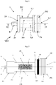
- Fig. 3 shows an embodiment of a gas distribution outlet 100 in which is mounted a detachable tip guide 108 according to the invention. Its overall architecture is very similar to that of a vacuum distribution outlet, that is to say a depression. A major difference, however, lies in the fact that, in a vacuum distribution outlet, the vacuum suction (ie depression), that is to say the circulation of the gas sucked through the outlet, takes place in the direction opposite to that of gas flow within the outlet 100 of Fig. 3 .
- the vacuum suction ie depression
- the gas eg air
- the proximal orifice 104 serves to aspirate gas and not to distribute it.
- the valve ball is not completely spherical but comprises for example only a hemispherical head on which the rod 111 of the tip guide 108 comes to rest through the connecting channel 122, as explained above.
- the sockets 1 of the invention are generally arranged on walls, such as walls or the like, of hospital buildings and are designed to allow the supply of either therapeutic gases, ie medical gases, in particular oxygen, nitrous oxide, air or any other gas or gas mixture, or medical vacuum (ie a depression) used to operate aspirations in particular of biological fluids, for example blood or other biological fluids.
- therapeutic gases ie medical gases, in particular oxygen, nitrous oxide, air or any other gas or gas mixture
- medical vacuum ie a depression
Landscapes
- Engineering & Computer Science (AREA)
- General Engineering & Computer Science (AREA)
- Mechanical Engineering (AREA)
- Separation Using Semi-Permeable Membranes (AREA)
- Connector Housings Or Holding Contact Members (AREA)
- Sampling And Sample Adjustment (AREA)
Abstract
L'invention concerne un guide-embout (108) pour prise de distribution de fluide (100), c'est-à-dire de gaz ou vide, comprenant une partie avant et une partie arrière solidarisées l'une à l'autre, de manière détachable. La partie arrière (108B) comprend un élément de filtration (1) incluant une pièce-support (2) portant des membranes de filtration (6) de gaz agencées des ouvertures latérales (5). La partie avant (108A) comprend une tête de raccordement (210) avec un passage axial de gaz (211) et des moyens de fixation (130) pour permettre une fixation détachable du guide-embout (108) dans une prise de distribution de fluide (100). La pièce-support (2) de l'élément de filtration (1) de la partie arrière (108B) du guide-embout (108) est en matériau polymère, alors que la tête de raccordement (210) de la partie avant (108A) est en matériau métallique. Prise de distribution de fluide (100) ayant un corps de prise (102) dans lequel est agencé un tel guide-embout (108) incluant un tel élément de filtration (1).The invention relates to a tip guide (108) for a fluid (100), that is to say gas or vacuum, distribution outlet, comprising a front part and a rear part secured to one another, detachable. The rear part (108B) comprises a filtration element (1) including a support part (2) carrying gas filtration membranes (6) arranged in side openings (5). The front portion (108A) includes a connection head (210) with an axial gas passage (211) and attachment means (130) to allow releasable attachment of the tip guide (108) in a fluid delivery outlet (100). The support piece (2) of the filter element (1) of the rear part (108B) of the bit guide (108) is made of polymer material, while the connection head (210) of the front part (108A ) is made of metallic material. Fluid distribution outlet (100) having an outlet body (102) in which is arranged such a tip guide (108) including such a filter element (1).
Description
L'invention concerne un guide-embout pour prise de distribution de fluide (i.e. gaz ou vide) et une prise murale de distribution de fluide équipée d'un tel guide-embout incluant un tel élément de filtration destinée à être utilisée dans un bâtiment hospitalier ou analogue, typiquement une prise murale fixée à une paroi verticale, servant à fournir du gaz ou du vide.The invention relates to a nozzle guide for a fluid distribution outlet (ie gas or vacuum) and a fluid distribution wall outlet equipped with such a nozzle guide including such a filtration element intended for use in a hospital building. or the like, typically a wall outlet attached to a vertical wall, serving to supply gas or vacuum.
Les prises de distribution de fluide sont utilisées pour distribuer les fluides, en particulier les gaz médicaux (i.e. un gaz pur ou un mélange gazeux) ou le vide (i.e. dépression < 1 atm), au sein des bâtiments hospitaliers ou analogues. Elles sont couramment appelées « prises murales » ou « raccords muraux » car elles sont généralement montées soit directement sur les parois, c'est-à-dire les murs ou analogues, des bâtiments hospitaliers, soit indirectement, par exemple en étant intégrées à un boitier ou analogue qui est lui-même monté sur une paroi, en particulier dans les chambres des patients, dans les salles d'opération ou de soins, notamment les salles de réanimation, ou d'autres piècesFluid distribution outlets are used to distribute fluids, in particular medical gases (i.e. pure gas or a gas mixture) or vacuum (i.e. depression <1 atm), within hospital buildings or the like. They are commonly called "wall outlets" or "wall fittings" because they are generally mounted either directly on the walls, that is to say the walls or the like, of hospital buildings, or indirectly, for example by being integrated into a unit. housing or the like which is itself mounted on a wall, in particular in patient rooms, in operating or treatment rooms, in particular resuscitation rooms, or other rooms
Les prises murales permettent de fournir les fluides médicaux, c'est-à-dire les gaz médicaux véhiculés par les réseaux de canalisations de gaz parcourant les bâtiments hospitaliers, aux appareils et équipements utilisés pour traiter et soigner les patients au sein de ces bâtiments, en particulier les gaz thérapeutiques, tel que l'oxygène, le protoxyde d'azote ou l'air, ou le vide médical (i.e. dépression) permettant d'opérer des aspirations notamment de liquides biologiques, par exemple le sang ou d'autres liquides biologiques.The wall outlets are used to supply medical fluids, that is to say the medical gases conveyed by the gas pipeline networks running through hospital buildings, to the devices and equipment used to treat and care for patients within these buildings, in particular therapeutic gases, such as oxygen, nitrous oxide or air, or medical vacuum (ie depression) making it possible to operate aspirations in particular of biological liquids, for example blood or other liquids biological.
Ainsi, le document
Elle comprend un corps de prise de forme allongée comprenant une cavité ou passage central traversant axialement le corps de prise de sorte de relier fluidiquement une extrémité amont, aussi appelée extrémité d'entrée ou extrémité distale, à une extrémité aval, aussi appelée extrémité de sortie ou extrémité proximale comprenant un orifice de fourniture de fluide, c'est-à-dire de gaz ou de vide. Le fluide « circule » dans la prise, lorsqu'un connecteur d'un appareil ou équipement médical, notamment le connecteur d'une conduite de gaz, est raccordé mécaniquement et fluidiquement à la prise.It comprises an elongated socket body comprising a central cavity or passage axially passing through the socket body so as to fluidly connect an upstream end, also called the inlet end or distal end, to a downstream end, also called the outlet end. or proximal end comprising an orifice for supplying fluid, i.e. gas or empty. Fluid "flows" through the outlet when a connector of a medical device or equipment, including the connector of a gas line, is mechanically and fluidly connected to the outlet.
Des éléments de contrôle du passage de fluide internes à la prise murale permettent de contrôler la libération du gaz, en particulier d'empêcher toute délivrance du gaz quand aucun connecteur s'y est branché. Ces éléments de contrôle du passage de fluide comprennent un guide-embout extractible agencé du côté proximal de la prise, c'est-à-dire vers l'avant de la prise, et une chambre à bille-clapet extractible, du côté distal de la prise, c'est-à-dire vers l'arrière ou le fond de la prise, qui sert à empêcher toute circulation de fluide lorsque le guide-embout est extrait du corps de prise, ou à limiter le débit de fuite.Fluid passage control elements internal to the wall outlet allow gas release to be controlled, in particular to prevent gas from being delivered when no connector is plugged into it. These fluid passage control elements comprise an extractable tip guide arranged on the proximal side of the socket, i.e. towards the front of the socket, and an extractable ball-valve chamber, on the distal side of the socket. the socket, that is to say towards the rear or the bottom of the socket, which serves to prevent any circulation of fluid when the tip guide is withdrawn from the socket body, or to limit the leakage rate.
Le guide-embout comprend un clapet de tête coulissant et l'orifice de sortie de gaz ou d'aspiration pour le vide. Le clapet de tête coulissant coopère avec un siège de clapet pour assurer ou, à l'inverse, interrompre l'étanchéité fluidique entre eux et ainsi empêcher ou, à l'inverse, autoriser le passage de fluide, i.e. gaz ou vide, lorsqu'un connecteur d'un appareil ou équipement médical est raccordé à la prise murale. Un élément élastique, tel un ressort, agit sur le clapet de tête coulissant pour le repousser en direction du siège de clapet.The bit guide includes a sliding head valve and the gas outlet or vacuum suction port. The sliding head valve cooperates with a valve seat to ensure or, conversely, interrupt the fluidic seal between them and thus prevent or, conversely, allow the passage of fluid, ie gas or vacuum, when ' a connector of a medical device or equipment is connected to the wall outlet. An elastic element, such as a spring, acts on the sliding head valve to push it back towards the valve seat.
Le guide-embout comprend ou est formé habituellement deux parties, à savoir une partie arrière et une partie avant, fixées l'une à l'autre, par exemple par vissage, lesquelles sont typiquement en métal, par exemple en acier inoxydable.The bit guide usually comprises or is formed in two parts, namely a rear part and a front part, fixed to each other, for example by screwing, which are typically made of metal, for example stainless steel.
La partie avant ou « tête » du guide-embout comprend des moyens de fixation dudit guide-embout au sein de la prise de distribution de fluide, par exemple un filetage périphérique externe, et est par ailleurs traversé par un passage axial en communication fluidique avec l'orifice de la partie arrière du guide-embout qui communique fluidiquement avec le logement interne de la partie arrière du guide-embout.The front part or "head" of the tip guide comprises means for fixing said tip guide within the fluid distribution outlet, for example an external peripheral thread, and is also crossed by an axial passage in fluid communication with the orifice in the rear part of the bit guide which fluidly communicates with the internal housing of the rear part of the bit guide.
La partie arrière ou « corps » de guide-embout comprend une paroi périphérique délimitant un logement interne, i.e. un volume interne ou lumen, s'étendant entre une extrémité ouverte et une extrémité borgne. L'extrémité ouverte porte un orifice communiquant avec le logement interne, alors que la paroi périphérique comprenant une ou plusieurs ouvertures latérales de passage de gaz communiquant avec le logement interne. Le fluide circule au travers des ouvertures latérales et/ou de l'orifice pour entrer ou sortir du logement interne. Le clapet de tête coulissant est agencé mobile dans le logement interne.The rear part or “body” of the tip guide comprises a peripheral wall defining an internal housing, ie an internal volume or lumen, extending between an open end and a blind end. The open end carries an orifice communicating with the internal housing, while the wall peripheral comprising one or more lateral gas passage openings communicating with the internal housing. Fluid circulates through the side openings and / or the orifice to enter or exit the internal housing. The sliding head valve is arranged movably in the internal housing.
Ce type de prise murale doit subir régulièrement des opérations de maintenance, notamment afin de garantir leur bon fonctionnement, de remplacer les éléments usés ou détériorés (e.g. utilisation intensive), de les nettoyer.... Lors de ces opérations, il faut pouvoir démonter puis remonter facilement et rapidement les différents éléments internes de la prise murale, en particulier le guide-embout situé vers l'avant du corps de prise et la chambre à bille-clapet. Il doit aussi être possible de remplacer uniquement les éléments usés ou détériorés du guide-embout, sans qu'il ne soit besoin de les remplacer tous, en particulier ceux qui ne sont pas usés ou détériorés.This type of wall outlet must undergo regular maintenance operations, in particular in order to guarantee their correct functioning, to replace worn or deteriorated elements (eg intensive use), to clean them .... During these operations, it is necessary to be able to disassemble then easily and quickly reassemble the various internal elements of the wall socket, in particular the tip guide located towards the front of the socket body and the ball-valve chamber. It should also be possible to replace only the worn or damaged parts of the bit guide, without the need to replace all of them, in particular those which are not worn or damaged.
Enfin, il faut également assurer une filtration du fluide (i.e. gaz ou vide) traversant la prise murale afin de garantir qu'il soit exempt de poussières ou autres contaminants/polluants solides.Finally, it is also necessary to ensure filtration of the fluid (i.e. gas or vacuum) passing through the wall outlet to ensure that it is free of dust or other contaminants / solid pollutants.
Un problème est de pouvoir améliorer la structure du guide-embout d'une prise de distribution de fluide (i.e. gaz ou vide), en particulier la partie arrière du guide-embout, de manière à pouvoir répondre aux différentes exigences et/ou problématiques susmentionnées. De plus, un autre problème concerne la fabrication du guide-embout qui génère actuellement beaucoup de déchets métalliques, sachant que le guide-embout doit par ailleurs être robuste pour résister aux opérations de connexion/déconnexion fréquentes de tuyaux flexibles ou d'appareils ou dispositifs médicaux à la prise de distribution de fluide intégrant le guide-embout.One problem is to be able to improve the structure of the tip guide of a fluid distribution outlet (ie gas or vacuum), in particular the rear part of the tip guide, so as to be able to meet the various aforementioned requirements and / or problems. . In addition, another problem relates to the manufacture of the bit guide which currently generates a lot of metal waste, knowing that the bit guide must also be robust to withstand the frequent connection / disconnection operations of flexible hoses or devices or devices. medical devices to the fluid distribution socket integrating the tip guide.
La solution concerne alors un guide-embout pour prise de distribution de fluide, i.e. gaz ou vide, comprenant une partie avant et une partie arrière solidarisées l'une à l'autre, dans lequel :
- la partie arrière comprend un élément de filtration comprenant une pièce-support comprenant une paroi périphérique délimitant un logement interne et s'étendant entre une extrémité ouverte comprenant un orifice et une extrémité borgne, l'orifice communiquant avec le logement interne, et la paroi périphérique comprenant en outre au moins une ouverture latérale communiquant avec le logement interne, au moins une membrane de filtration de gaz étant agencée dans ladite au moins une ouverture latérale de manière à recouvrir ladite au moins une ouverture latérale, et
- la partie avant comprend une tête de raccordement comprenant un passage axial de gaz en communication fluidique avec le logement interne de l'élément de filtration de gaz, et des moyens de fixation configurés pour permettre une fixation détachable du guide-embout au sein d'une prise de distribution de fluide, et
- la partie avant et la partie arrière comprennent en outre des moyens de solidarisation réciproques permettant d'assurer une fixation détachable desdites partie avant et partie arrière, l'une à l'autre,
caractérisé en ce que : - la pièce-support de l'élément de filtration de la partie arrière est en matériau polymère, et
- la tête de raccordement de la partie avant est en matériau métallique.
- the rear part comprises a filtration element comprising a support piece comprising a peripheral wall defining an internal housing and extending between an open end comprising an orifice and a blind end, the orifice communicating with the internal housing, and the peripheral wall further comprising at least one lateral opening communicating with the internal housing, at least one gas filtration membrane being arranged in said at least one lateral opening so as to cover said at least one lateral opening, and
- the front portion comprises a connection head comprising an axial gas passage in fluid communication with the internal housing of the gas filter element, and attachment means configured to allow releasable attachment of the tip guide within a fluid distribution outlet, and
- the front part and the rear part further comprise reciprocal securing means making it possible to ensure a detachable fixing of said front part and rear part, to one another,
characterized in that: - the support part of the filter element of the rear part is made of polymer material, and
- the connection head of the front part is made of metallic material.
La solution de l'invention résout les problèmes susmentionnés étant donné qu'un guide-embout en deux matériaux différents, à savoir formé :
- d'un élément de filtration formé en tout ou en partie de polymère permet de réduire la quantité de déchets métalliques générés pendant sa fabrication et permet une fabrication plus simple de cet élément, par exemple par (sur)moulage,
- et d'une tête de raccordement en métal permet d'offrir une robustesse suffisante à l'ensemble et d'assurer une connexion efficace aux tuyaux flexibles ou autres appareils ou dispositifs médicaux qui seront raccordés à la prise de distribution de fluide intégrant ce guide-embout.
- a filtration element formed in whole or in part from polymer makes it possible to reduce the quantity of metal waste generated during its manufacture and allows a simpler manufacture of this element, for example by (over) molding,
- and a metal connection head makes it possible to offer sufficient robustness to the assembly and to ensure an efficient connection to flexible hoses or other medical devices or devices which will be connected to the fluid distribution outlet incorporating this guide. mouthpiece.
Selon le mode de réalisation considéré, le guide-embout de l'invention peut comprendre l'une ou plusieurs des caractéristiques suivantes :
- les moyens de fixation de la partie avant du guide-embout sont configurés pour permettre une fixation détachable du guide-embout au sein d'une prise de distribution de fluide comprennent un filetage périphérique externe destiné à venir coopérer avec un taraudage aménagé dans le corps de la prise distribution de fluide.
- la pièce-support de l'élément de filtration de la partie arrière est en polyamide.
- les moyens de solidarisation réciproques comprennent un taraudage et un filetage coopérant l'un avec l'autre, le filetage étant agencé dans la partie avant et le taraudage étant agencé dans la partie arrière, ou inversement.
- les moyens de fixation de la partie avant du guide-embout configurés pour permettre une fixation détachable du guide-embout au sein d'une prise de distribution de fluide comprennent un filetage périphérique externe destiné à venir coopérer avec un taraudage aménagé dans le corps de la prise distribution de fluide.
- la tête de raccordement de la partie avant est en acier inoxydable ou en laiton, de préférence en acier inoxydable ou en laiton revêtu d'un revêtement métallique externe, notamment de chrome ou de nickel.
- la tête de raccordement de la partie avant est (au moins en partie) cylindrique.
- la pièce-support a une forme générale tubulaire à fond borgne, c'est-à-dire fermée à une extrémité.
- l'extrémité ouverte de la pièce-support comprend un orifice au travers duquel le fluide (i.e. gaz ou vide) peut circuler, c'est-à-dire entrer ou sortir de l'élément de filtration.
- le logement interne de la pièce-support a une forme cylindrique.
- la pièce-support comprend plusieurs ouvertures latérales, chaque ouverture latérale comprenant une membrane de filtration de gaz.
- la pièce-support comprend de 2 à 6 ouvertures latérales, de préférence de 2 à 4 ouvertures latérales.
- les ouvertures latérales sont préférentiellement identiques les unes aux autres ou, selon un autre mode de réalisation, elles peuvent avoir des formes différentes les uns des autres.
- les membranes de filtration recouvrent complètement les ouvertures latérales dans lesquelles elles sont agencées, c'est-à-dire que les sections de passage des ouvertures latérales sont totalement obturées par les membranes de filtration.
- les membranes de filtration sont conçues pour filtrer le fluide (i.e. gaz ou vide) qui les traversent.
- les membranes de filtration sont formées d'une pièce unique de forme cylindrique.
- la pièce cylindrique portant les membranes de filtration a un diamètre inférieur ou égal, de préférence approximativement égal, au diamètre interne du logement interne de la pièce-support.
- selon un mode de réalisation, la pièce cylindrique portant les membranes de filtration est insérée et non fixée (i.e. libre) dans le logement interne de la pièce-support.
- selon un autre mode de réalisation, la pièce cylindrique portant les membranes de filtration est insérée et fixée (i.e. libre) dans le logement interne de la pièce-support.
- les membranes de filtration sont fixées à la pièce-support par collage, thermo-soudage, surmoulage ou autre, de préférence par surmoulage de la pièce-support.
- les membranes de filtration sont formées d'une toile ou tissu en polymère.
- les membranes de filtration comprennent des pores compris entre 50 et 80 µm, en particulier lorsqu'elles sont destinées à filtrer un gaz, notamment un gaz médical.
- selon un autre mode de réalisation, les membranes de filtration comprennent des pores compris entre 200 et 300 µm, en particulier lorsqu'elles sont destinées à filtrer du vide ou de l'air-instrument.
- les membranes de filtration sont formées d'une pièce unique de forme cylindrique formée d'une toile ou d'un tissu en polymère.
- la pièce-support est surmoulée autour de la pièce unique de forme cylindrique formée d'une toile ou d'un tissu en polymère.
- les membranes de filtration sont formées d'une pièce en polymère de forme cylindrique autour de laquelle est surmoulée la pièce-support.
- la pièce-support comprend un axe longitudinal (XX), c'est-à-dire qu'elle s'étend axialement selon l'axe longitudinal (XX).
- la pièce-support est une pièce de révolution.
- chaque membrane de filtration a une épaisseur inférieure à l'épaisseur de la paroi périphérique autour de l'ouvertures latérale dans laquelle elle est agencée.
- les membranes de filtration sont préférentiellement en polymère, par exemple en polyamide, tel du Nylon®.
- les membranes de filtration sont, selon un autre mode de réalisation, en métal, par exemple de l'acier inoxydable.
- la pièce-support forme une armature, i.e. un châssis ou cadre, portant les membranes de filtration.
- l'armature constituant la pièce-support est formée d'une pièce en polymère de type polyamide.
- la pièce-support a une forme générale cylindrique.
- les ouvertures latérales sont de section carrée ou rectangulaire, ou autre, par exemple ovale ou ellipsoïdale.
- la pièce-support comprend plusieurs tronçons successifs de diamètres externes différents, i.e. des tronçons cylindriques ou approximativement cylindriques.
- la pièce-support comprend un tronçon amont à son extrémité ouverte ; un tronçon aval à son extrémité borgne ; et au moins un tronçon intermédiaire agencé entre les tronçons amont et aval, ledit tronçon intermédiaire comprenant les ouvertures.
- les tronçons amont et aval sont cylindriques.
- le tronçon intermédiaire est cylindrique ou approximativement cylindrique.
- le diamètre externe du tronçon intermédiaire comprenant les ouvertures est inférieur aux diamètres externes des tronçons amont et aval.
- les tronçons amont et aval sont reliés l'un à l'autre par des éléments de paroi longilignes formant tout ou partie du tronçon intermédiaire.
- les éléments de paroi longilignes sont parallèles les uns aux autres et à l'axe longitudinal (XX).
- les ouvertures du tronçon intermédiaire sont bordées par les tronçons amont et aval, et les éléments de paroi longilignes.
- les tronçons amont et aval, et les éléments de paroi longilignes sont formés d'une seule pièce, par exemple par moulage.
- les tronçons amont et aval, et les éléments de paroi longilignes sont formés de matériau polymère, i.e. sont en plastique, typiquement en polyamide.
- les tronçons amont et aval, et les éléments de paroi longilignes de la pièce-support forme l'armature, i.e. le châssis ou cadre, portant les membranes de filtration.
- le diamètre externe du tronçon amont est par exemple compris entre 12 et 16 mm.
- le diamètre externe du tronçon aval est par exemple compris entre 11 et 15 mm.
- le diamètre externe du tronçon cylindrique intermédiaire est par exemple compris entre 11 et 15 mm.
- l'extrémité borgne de la pièce-support comprend une tige-poussoir faisant saillie axialement (axe XX) au centre de la face externe de l'extrémité borgne.
- la pièce-support a une longueur de l'ordre de 20 à 25 mm.
- le logement interne de la pièce-support a un diamètre interne de l'ordre de 9 à 12 mm.
- l'extrémité ouverte de la pièce-support comprend un taraudage permettant de la fixer à la partie avant d'un guide-embout.
- un clapet de tête coulissant est agencé dans le logement interne de l'élément de filtration.
- un moyen élastique, tel un ressort, est agencé dans le logement interne de l'élément de filtration.
- le moyen élastique est agencé pour agir sur, i.e. repousser, le clapet de tête en direction d'un siège de clapet.
- la partie avant du guide-embout comprend une gorge périphérique annulaire et un élément de joint agencé dans ladite gorge périphérique annulaire, en particulier un joint torique.
- la partie avant du guide-embout comprend le siège de clapet coopérant avec le clapet de tête.
- the fixing means of the front part of the bit guide are configured to allow a detachable fixing of the bit guide within a fluid distribution socket comprise an external peripheral thread intended to cooperate with an internal thread formed in the body of the fluid distribution outlet.
- the support piece for the filter element in the rear part is made of polyamide.
- the reciprocal securing means comprise an internal thread and a thread cooperating with one another, the thread being arranged in the front part and the internal thread being arranged in the rear part, or vice versa.
- the fixing means of the front part of the bit guide configured to allow a detachable fixing of the bit guide within a fluid distribution outlet comprise an external peripheral thread intended to cooperate with a thread formed in the body of the fluid distribution outlet.
- the connection head of the front part is made of stainless steel or of brass, preferably of stainless steel or of brass coated with an external metallic coating, in particular with chromium or nickel.
- the connection head of the front part is (at least in part) cylindrical.
- the support part has a generally tubular shape with a blind bottom, that is to say closed at one end.
- the open end of the support piece comprises an orifice through which the fluid (ie gas or vacuum) can circulate, that is to say enter or leave the filter element.
- the internal housing of the support part has a cylindrical shape.
- the support piece comprises several side openings, each side opening comprising a gas filtration membrane.
- the support piece comprises from 2 to 6 side openings, preferably from 2 to 4 side openings.
- the side openings are preferably identical to each other or, according to another embodiment, they can have different shapes from each other.
- the filtration membranes completely cover the side openings in which they are arranged, i.e. the sections of passage of the side openings are completely closed by the filtration membranes.
- filtration membranes are designed to filter the fluid (ie gas or vacuum) passing through them.
- the filtration membranes are formed from a single cylindrical piece.
- the cylindrical part carrying the filtration membranes has a diameter less than or equal, preferably approximately equal, to the internal diameter of the internal housing of the support part.
- according to one embodiment, the cylindrical part carrying the filtration membranes is inserted and not fixed (ie free) in the internal housing of the support part.
- according to another embodiment, the cylindrical part carrying the filtration membranes is inserted and fixed (ie free) in the internal housing of the support part.
- the filtration membranes are fixed to the support part by gluing, heat-welding, overmolding or the like, preferably by overmolding of the support part.
- the filtration membranes are formed from a fabric or polymer fabric.
- the filtration membranes comprise pores of between 50 and 80 μm, in particular when they are intended to filter a gas, in particular a medical gas.
- according to another embodiment, the filtration membranes comprise pores of between 200 and 300 μm, in particular when they are intended to filter vacuum or air-instrument.
- the filtration membranes are formed from a single cylindrical piece formed of a canvas or a polymer fabric.
- the support part is molded around the single cylindrical part formed of a canvas or a polymer fabric.
- the filtration membranes are formed from a polymer part of cylindrical shape around which the support part is overmolded.
- the support part comprises a longitudinal axis (XX), that is to say that it extends axially along the longitudinal axis (XX).
- the support part is a part of revolution.
- each filtration membrane has a thickness less than the thickness of the peripheral wall around the side openings in which it is arranged.
- filtration membranes are preferably made of polymer, for example polyamide, as Nylon ®.
- the filtration membranes are, according to another embodiment, made of metal, for example stainless steel.
- the support part forms a frame, ie a frame or frame, carrying the filtration membranes.
- the frame constituting the support piece is formed from a piece of polyamide-type polymer.
- the support part has a generally cylindrical shape.
- the side openings are of square or rectangular section, or the like, for example oval or ellipsoidal.
- the support part comprises several successive sections of different external diameters, ie cylindrical or approximately cylindrical sections.
- the support part comprises an upstream section at its open end; a downstream section at its blind end; and at least one intermediate section arranged between the upstream and downstream sections, said intermediate section comprising the openings.
- the upstream and downstream sections are cylindrical.
- the intermediate section is cylindrical or approximately cylindrical.
- the external diameter of the intermediate section comprising the openings is smaller than the external diameters of the upstream and downstream sections.
- the upstream and downstream sections are connected to each other by elongated wall elements forming all or part of the intermediate section.
- the elongated wall elements are parallel to each other and to the longitudinal axis (XX).
- the openings of the intermediate section are bordered by the upstream and downstream sections, and the elongated wall elements.
- the upstream and downstream sections, and the elongated wall elements are formed in one piece, for example by molding.
- the upstream and downstream sections, and the elongated wall elements are formed from a polymer material, ie are made of plastic, typically polyamide.
- the upstream and downstream sections, and the elongated wall elements of the support part form the frame, ie the frame or frame, carrying the filtration membranes.
- the external diameter of the upstream section is for example between 12 and 16 mm.
- the external diameter of the downstream section is for example between 11 and 15 mm.
- the external diameter of the intermediate cylindrical section is for example between 11 and 15 mm.
- the blind end of the support part comprises a push rod projecting axially (axis XX) at the center of the external face of the blind end.
- the support part has a length of the order of 20 to 25 mm.
- the internal housing of the support part has an internal diameter of the order of 9 to 12 mm.
- the open end of the support piece has a thread for fixing it to the front part of a bit guide.
- a sliding head valve is arranged in the internal housing of the filter element.
- an elastic means, such as a spring, is arranged in the internal housing of the filter element.
- the elastic means is arranged to act on, ie push back, the head valve in the direction of a valve seat.
- the front part of the bit guide comprises an annular peripheral groove and a seal element arranged in said annular peripheral groove, in particular an O-ring.
- the front part of the nozzle guide includes the valve seat cooperating with the head valve.
L'invention concerne aussi une prise de distribution de fluide, c'est-à-dire de gaz ou de vide (i.e. dépression), comprenant un corps de prise dans lequel est agencé un élément de filtration de gaz selon l'invention.The invention also relates to a fluid distribution outlet, that is to say gas or vacuum (i.e. vacuum), comprising an outlet body in which is arranged a gas filtration element according to the invention.
Selon le mode de réalisation considéré, la prise de distribution de fluide de l'invention peut comprendre l'une ou plusieurs des caractéristiques suivantes :
- le corps de prise comprend en outre une chambre à bille contenant une bille-clapet coopérant avec la tige-poussoir de la pièce-support du guide-embout.
- la chambre à bille est extractible.
- la chambre à bille est visée dans le corps de prise, en particulier dans le passage central du corps de prise.
- elle est une prise murale, c'est-à-dire qu'elle comprend des moyens de fixation permettant de la fixer à une paroi, tel un mur ou analogue.
- le guide-embout est monté de manière amovible, c'est-à-dire démontable, dans le corps de prise.
- elle est reliée à une canalisation de gaz ou de vide, en particulier au réseau de canalisations de gaz ou de vide (i.e. dépression) d'un bâtiment hospitalier.
- the engagement body further comprises a ball chamber containing a valve ball cooperating with the push rod of the support part of the tip guide.
- the ball chamber is removable.
- the ball chamber is aimed in the grip body, in particular in the central passage of the grip body.
- it is a wall socket, that is to say it comprises fixing means allowing it to be fixed to a wall, such as a wall or the like.
- the bit guide is removably mounted, that is to say removable, in the socket body.
- it is connected to a gas or vacuum pipe, in particular to the gas or vacuum pipe network (ie depression) of a hospital building.
L'invention concerne en outre une utilisation d'une prise de distribution de fluide selon l'invention pour distribuer, i.e. fournir, un gaz ou mélange gazeux, ou du vide (i.e. aspiration à une pression < 1 atm) au sein d'un bâtiment hospitalier.The invention further relates to a use of a fluid distribution outlet according to the invention for distributing, ie supplying, a gas or gaseous mixture, or a vacuum (ie suction at a pressure <1 atm) within a hospital building.
Le gaz ou mélange gazeux peut être de l'oxygène, de l'air, un mélange N2O/O2.... ou autre.The gas or gaseous mixture can be oxygen, air, an N 2 O / O 2 mixture, etc. or the like.
La prise de distribution de fluide selon l'invention est reliée fluidiquement au réseau de canalisation du bâtiment hospitalier.The fluid distribution outlet according to the invention is fluidly connected to the pipe network of the hospital building.
L'invention va maintenant être mieux comprise grâce à la description détaillée suivante, faite à titre illustratif mais non limitatif, en référence aux figures annexées parmi lesquelles :
-
Fig. 1 est une vue latérale d'un élément de filtration de gaz formant la partie arrière d'un guide-embout de prise de distribution de fluide selon l'invention, -
Fig. 2 est une vue latérale schématique d'un guide-embout selon l'invention, et -
Fig. 3 est une vue en coupe d'une prise de distribution de gaz incluant un guide-embout selon l'invention. -
Fig. 3 représente un mode de réalisation d'une prise dedistribution 100 de gaz selon l'invention, par exemple d'oxygène ou d'air médical, comprenant un corps de prise 102 de forme allongée, selon un axe longitudinal AA, lequel est traversé axialement par un passage central 103 formant un logement interne au sein duquel sont agencés des éléments de contrôle du passage de gaz, en particulier le guide-embout 108 selon l'invention illustré enFig. 2 et une chambre à bille 122, comme expliqué ci-après. Une telle architecture est classique.
-
Fig. 1 is a side view of a gas filtration element forming the rear part of a guide-tip for taking fluid distribution according to the invention, -
Fig. 2 is a schematic side view of a tip guide according to the invention, and -
Fig. 3 is a sectional view of a gas distribution outlet including a tip guide according to the invention. -
Fig. 3 shows an embodiment of anoutlet 100 for gas according to the invention, for example oxygen or medical air, comprising anoutlet body 102 of elongated shape, along a longitudinal axis AA, which is axially traversed by acentral passage 103 forming an internal housing within which are arranged elements for controlling the passage of gas, in particular thetip guide 108 according to the invention illustrated inFig. 2 and aball chamber 122, as explained below. Such architecture is classic.
Le guide-embout 108 selon l'invention extractible est formé de deux parties principales fixées l'une à l'autre, par exemple par vissage, à savoir une partie avant 108A incluant une « tête » de raccordement 210 de guide-embout 108 et une partie arrière 108B ou « corps » de guide-embout 108 comprenant l'élément de filtration de gaz 1, comme illustré sur les
Selon l'invention, la pièce-support 2 de l'élément de filtration 1 de la partie arrière 108B du guide-embout 108 est en matériau polymère, de préférence en polyamide, alors que la tête de raccordement 210 de la partie avant 108A est en matériau métallique, de préférence en acier inoxydable ou en laiton, de préférence en acier inoxydable ou en laiton revêtu d'un revêtement métallique externe, notamment de chrome ou de nickel.According to the invention, the
La partie avant 108A comprend des moyens de fixation 130 du guide-embout 108 au sein de la prise de distribution de fluide 100, à savoir ici un filetage périphérique externe schématisé sur la
Dans le cas de la prise 100 de
Par ailleurs, la partie arrière 108B du guide-embout 108 comprend l'élément de filtration de gaz 1 selon l'invention, comme illustré en
Comme détaillé en
L'orifice 4 de l'élément de filtration de gaz 1 communique avec le logement interne 7 de celui-ci. La paroi périphérique 3 comprenant en outre des ouvertures latérales 5, par exemple de 2 à 4 ouvertures latérales, ici de forme rectangulaire, communiquant avec le logement interne 7. Une membrane de filtration 6 de gaz est agencée dans chacune des ouvertures latérales 5 de manière à recouvrir les ouvertures latérales 5 de sorte que le gaz passant par ces ouvertures latérales 5 soit filtré par les membranes de filtration 6 qui y sont disposées. Le fluide, i.e. gaz ou vide, circule au travers des ouvertures latérales 5 et de l'orifice 4 pour entrer ou sortir du logement interne 7.The orifice 4 of the
Un clapet de tête 109 coulissant est agencé mobile selon l'axe AA dans le logement interne 7, i.e. coulissant en translation, au sein dudit logement axial 7, comme illustré en
Par ailleurs, le guide-embout 108 de l'invention comprend aussi un élément d'étanchéité 105 permettant d'assurer une étanchéité fluidique entre ledit guide-embout 108 et le corps de prise 102 au sein duquel il est fixé de manière amovible, c'est-à-dire détachable.Furthermore, the
Un autre élément d'étanchéité 117, porté par le clapet 109, permet quant à lui d'assurer une étanchéité fluidique entre le clapet 109 et le siège de clapet 110, lorsque le clapet de tête 109 est repoussé contre le siège de clapet 110 par l'élément élastique 111.Another sealing
Par ailleurs, la prise 100 de distribution de fluide de
La chambre à bille-clapet 122 est aussi extractible du corps de prise 102 afin de permettre sa maintenance. Elle permet d'empêcher que le gaz ne puisse s'échapper de la prise 100 ou que l'aspiration par le vide (i.e. dépression) ne se fasse, c'est-à-dire que de l'air ne puisse entrer dans le réseau de vide relié à la prise 100 et y faire remonter la pression (< 1 atm) qui y règne, lorsque les éléments de contrôle du passage de gaz, typiquement le guide-embout 108, sont démontés et extraits du corps de prise 102, notamment lors d'une opération de vérification, de maintenance ou de remplacement.The ball-
La bille-clapet 120 fait office de clapet de sécurité venant, sous l'effet de la pression fluidique ou de la dépression (i.e. vide) s'exerçant sur la bille-clapet 120 en cas de démontage du guide-embout 108, appuyer sur et obturer un siège de clapet situé dans le compartiment 121. A l'inverse, quand les éléments de contrôle du passage de gaz sont montés dans le corps de prise 102, le guide-embout 108 vient appuyer sur la bille-clapet 120 pour la décoller du siège de clapet et autoriser ainsi la communication fluidique au travers du canal de liaison 123 reliant fluidiquement le compartiment 121 au passage axial 103 du corps 102 de la prise 100. Ceci peut se faire via une tige-poussoir 11, c'est-à-dire une tige ou expansion axiale, faisant saillie sur la surface externe arrière du guide-embout 8 et solidaire de celui-ci, qui est orientée de sorte de traverser axialement le canal de liaison 123 pour venir appuyer sur la bille-clapet 120 et ainsi la décoller de son siège. La tige axiale 11 est portée par la pièce-support 2 de l'élément de filtration 1 du guide-embout 8 de l'invention, comme visible sur les
La prise de distribution 1 de fluide de l'invention, telle celle illustrée en
La partie arrière 108B du guide-embout 108 comprend l'élément de filtration 1, illustré sur la
Cet élément de filtration 1 comprend, comme visible sur
Les tronçons amont 200 et aval 201 sont cylindriques et ont des diamètres externes égaux ou différents, par exemple compris entre 11 et 16 mm, alors que le tronçon intermédiaire 202 est cylindrique ou approximativement cylindrique, et a un diamètre inférieur au ou aux diamètres externes des tronçons amont 200 et aval 201, par exemple compris entre 11 et 15 mm. La pièce-support 2 a par exemple une longueur de l'ordre de 20 à 25 mm.The upstream 200 and downstream 201 sections are cylindrical and have equal or different external diameters, for example between 11 and 16 mm, while the
Les ouvertures 5 sont ici de forme rectangulaire mais, bien entendu, elles pourraient être d'une autre forme, par exemple de forme carrée, ovale, ellipsoïdale ou autre. Les membranes de filtration 6 ont des formes complémentaires de celles des ouvertures 5 de manière à les recouvrir complètement de sorte que tout le gaz passant au travers des ouvertures 5 soit filtré par ces membranes de filtration 6.The
Dans le mode de réalisation de la
Avantageusement, les tronçons amont 200 et aval 201, et les éléments de paroi longilignes 204 constituant l'élément de filtration 1 sont formés d'une seule pièce de polymère, i.e. plastique, par exemple par moulage ou analogue, typiquement un polyamide.Advantageously, the upstream 200 and downstream 201 sections, and the
Comme on le voit sur la
Le logement interne 7 de la pièce-support 2 a un diamètre interne de l'ordre de 9 à 12 mm de manière à pouvoir accueillir le clapet de tête 109 et le ressort 111, comme expliqué ci-avant.The
Afin de permettre de fixer l'élément de filtration 1 formant la partie arrière 108B du guide-embout 108, à la partie avant 108A du guide-embout 108, sont prévus des moyens de solidarisation réciproques 212 configurés pour assurer une fixation détachable desdites parties avant 108A et arrière 108B, l'une à l'autre, comme illustré en
Les membranes de filtration 6 agencées dans les ouvertures 5 sont conçues pour filtrer le fluide, i.e. gaz ou vide, qui les traversent. Elles peuvent être en polymère ou en métal, de préférence en polymère, par exemple en polyamide. Elles ont des pores ayant des dimensions inférieures aux particules qu'elles doivent arrêter, telles des poussières, des débris, des résidus, des bactéries ou toutes autres particules, par exemple des pores de diamètre compris entre 50 et 80 µm, lorsqu'elles sont destinées à filtrer un gaz, notamment un gaz médical (air médical, oxygène...), ou compris entre 200 et 300 µm, lorsqu'elles sont destinées à filtrer du vide (i.e. dépression) ou de l'air-instrument.The
Avantageusement, les membranes de filtration 6 sont constituées ou portées par une pièce unique de forme cylindrique préférentiellement formée d'une toile de polyamide, tel du Nylon®, autour de laquelle est surmoulé le reste de la pièce support 2, en particulier les tronçons amont 200 et aval 201, et les éléments de paroi longilignes 204 qui forment le cadre ou châssis. De préférence, on utilise pour former les membranes 6, une toile en polyamide de référence SEFAR-NITEX® commercialisée par la société Sefar.Advantageously, the
D'une façon générale, les prises 1 de l'invention sont généralement agencées sur des parois, tels des murs ou analogues, des bâtiments hospitaliers et sont conçues pour permettre de fournir soit des gaz thérapeutiques, i.e. gaz médicaux, en particulier de l'oxygène, du protoxyde d'azote, de l'air ou tout autre gaz ou mélange gazeux, soit du vide médical (i.e. une dépression) servant à opérer des aspirations notamment de liquides biologiques, par exemple le sang ou d'autres liquides biologiques.In general, the
Claims (10)
caractérisé en ce que :
characterized in that :
Applications Claiming Priority (1)
| Application Number | Priority Date | Filing Date | Title |
|---|---|---|---|
| FR2006072A FR3111407B1 (en) | 2020-06-10 | 2020-06-10 | Bi-Material Fluid Dispensing Wall Outlet Tip Guide |
Publications (2)
| Publication Number | Publication Date |
|---|---|
| EP3922894A1 true EP3922894A1 (en) | 2021-12-15 |
| EP3922894B1 EP3922894B1 (en) | 2023-03-15 |
Family
ID=73038076
Family Applications (1)
| Application Number | Title | Priority Date | Filing Date |
|---|---|---|---|
| EP21168445.1A Active EP3922894B1 (en) | 2020-06-10 | 2021-04-14 | Guiding end tip for a fluid distribution wall socket made of two materials |
Country Status (4)
| Country | Link |
|---|---|
| EP (1) | EP3922894B1 (en) |
| ES (1) | ES2946433T3 (en) |
| FR (1) | FR3111407B1 (en) |
| PT (1) | PT3922894T (en) |
Cited By (3)
| Publication number | Priority date | Publication date | Assignee | Title |
|---|---|---|---|---|
| CN115451220A (en) * | 2022-09-22 | 2022-12-09 | 南溪南山设备制造有限公司 | Shooting nail type air exhaust joint assembly |
| FR3133018A1 (en) | 2022-02-28 | 2023-09-01 | Air Liquide Sante France | Device for measuring the pressure of a fluid distribution socket in a hospital environment |
| FR3144642A1 (en) | 2023-01-03 | 2024-07-05 | Air Liquide Medical Systems | Fluid distribution socket with fitted cover |
Citations (4)
| Publication number | Priority date | Publication date | Assignee | Title |
|---|---|---|---|---|
| DE7500293U (en) * | 1974-01-10 | 1975-07-24 | L'air Liquide Sa Pour L'etude Et L' | Plug-in device for a fluid or vacuum distribution system |
| US4851118A (en) * | 1987-05-15 | 1989-07-25 | Nifco, Inc. | Fuel filter for motor vehicle |
| FR2628820A1 (en) | 1988-03-18 | 1989-09-22 | Air Liquide | Push-in connector for automatic safe shut=off of medical gases - has one-piece body with ball valve which shuts if connector is dismantled |
| WO2019063134A1 (en) * | 2017-09-27 | 2019-04-04 | Husqvarna Ab | Visible, removable filter for water tools |
-
2020
- 2020-06-10 FR FR2006072A patent/FR3111407B1/en active Active
-
2021
- 2021-04-14 PT PT211684451T patent/PT3922894T/en unknown
- 2021-04-14 EP EP21168445.1A patent/EP3922894B1/en active Active
- 2021-04-14 ES ES21168445T patent/ES2946433T3/en active Active
Patent Citations (4)
| Publication number | Priority date | Publication date | Assignee | Title |
|---|---|---|---|---|
| DE7500293U (en) * | 1974-01-10 | 1975-07-24 | L'air Liquide Sa Pour L'etude Et L' | Plug-in device for a fluid or vacuum distribution system |
| US4851118A (en) * | 1987-05-15 | 1989-07-25 | Nifco, Inc. | Fuel filter for motor vehicle |
| FR2628820A1 (en) | 1988-03-18 | 1989-09-22 | Air Liquide | Push-in connector for automatic safe shut=off of medical gases - has one-piece body with ball valve which shuts if connector is dismantled |
| WO2019063134A1 (en) * | 2017-09-27 | 2019-04-04 | Husqvarna Ab | Visible, removable filter for water tools |
Cited By (4)
| Publication number | Priority date | Publication date | Assignee | Title |
|---|---|---|---|---|
| FR3133018A1 (en) | 2022-02-28 | 2023-09-01 | Air Liquide Sante France | Device for measuring the pressure of a fluid distribution socket in a hospital environment |
| CN115451220A (en) * | 2022-09-22 | 2022-12-09 | 南溪南山设备制造有限公司 | Shooting nail type air exhaust joint assembly |
| FR3144642A1 (en) | 2023-01-03 | 2024-07-05 | Air Liquide Medical Systems | Fluid distribution socket with fitted cover |
| EP4397356A1 (en) | 2023-01-03 | 2024-07-10 | Air Liquide Medical Systems | Hospital wall outlet with nested cap for fluid dispensing |
Also Published As
| Publication number | Publication date |
|---|---|
| FR3111407B1 (en) | 2022-05-13 |
| FR3111407A1 (en) | 2021-12-17 |
| PT3922894T (en) | 2023-06-07 |
| ES2946433T3 (en) | 2023-07-18 |
| EP3922894B1 (en) | 2023-03-15 |
Similar Documents
| Publication | Publication Date | Title |
|---|---|---|
| EP3922894B1 (en) | Guiding end tip for a fluid distribution wall socket made of two materials | |
| EP3922895B1 (en) | Filtering element of a guiding end tip for a fluid distribution wall socket | |
| EP3922339A1 (en) | Guiding end tip for a fluid distribution wall socket including a filtering element with controlled porosity | |
| EP0431108B1 (en) | Oxygeno-phonation device | |
| EP3892906B1 (en) | Fluid distribution socket with chamber with removable ball-valve for use in hospitals | |
| EP3875136B1 (en) | Medical ventilator with a connection socket including an easily removable filter | |
| EP3719377A1 (en) | Wall socket for dispensing medical liquid with improved attachment and indexing | |
| EP0451062A1 (en) | Nasal mucus withdrawing device | |
| EP1762172B1 (en) | Device and method for cleaning an endoscope | |
| FR3111821A1 (en) | Fluid distribution outlet protected by a rigid case usable in a hospital environment | |
| FR3019991A1 (en) | AUTONOMOUS FILTERING AND GAS MIXING MODULE FOR ASSISTED VENTILATION APPARATUS | |
| FR3111405A1 (en) | Distribution wall outlet guide with unique identification marking | |
| FR3051776A1 (en) | LIQUID CONTAINER TIP FOR ADAPTING ON A TANK TIP | |
| FR3091741A1 (en) | Improved medical fluid delivery socket | |
| WO2021099479A1 (en) | Liquid container spout | |
| EP1325762B1 (en) | Demand valve for use in oxygenotherapy | |
| FR3091740A1 (en) | Medical fluid distribution socket with extractable tip guide | |
| FR3106182A1 (en) | Nickel-coated medical fluid outlet | |
| FR3091742A1 (en) | Gas distribution outlet with residual leakage maintenance system | |
| FR3106181A1 (en) | Medical fluid dispensing socket with extractable tip guide with colored front face | |
| FR2693786A1 (en) | Improvements introduced to valves for fluids. | |
| FR2835005A1 (en) | Mixer tap, e.g. for hospital use, has bell-shaped base that can be disengaged from delivery pipe connector to allow tap to be decontaminated | |
| EP4397356A1 (en) | Hospital wall outlet with nested cap for fluid dispensing | |
| EP0932421B1 (en) | Sucking or insufflating device for medical use, comprising a stop valve | |
| FR3112187A1 (en) | Die-cast medical fluid distribution wall outlet |
Legal Events
| Date | Code | Title | Description |
|---|---|---|---|
| PUAI | Public reference made under article 153(3) epc to a published international application that has entered the european phase |
Free format text: ORIGINAL CODE: 0009012 |
|
| STAA | Information on the status of an ep patent application or granted ep patent |
Free format text: STATUS: THE APPLICATION HAS BEEN PUBLISHED |
|
| AK | Designated contracting states |
Kind code of ref document: A1 Designated state(s): AL AT BE BG CH CY CZ DE DK EE ES FI FR GB GR HR HU IE IS IT LI LT LU LV MC MK MT NL NO PL PT RO RS SE SI SK SM TR |
|
| B565 | Issuance of search results under rule 164(2) epc |
Effective date: 20210915 |
|
| STAA | Information on the status of an ep patent application or granted ep patent |
Free format text: STATUS: REQUEST FOR EXAMINATION WAS MADE |
|
| 17P | Request for examination filed |
Effective date: 20220615 |
|
| RBV | Designated contracting states (corrected) |
Designated state(s): AL AT BE BG CH CY CZ DE DK EE ES FI FR GB GR HR HU IE IS IT LI LT LU LV MC MK MT NL NO PL PT RO RS SE SI SK SM TR |
|
| GRAP | Despatch of communication of intention to grant a patent |
Free format text: ORIGINAL CODE: EPIDOSNIGR1 |
|
| STAA | Information on the status of an ep patent application or granted ep patent |
Free format text: STATUS: GRANT OF PATENT IS INTENDED |
|
| INTG | Intention to grant announced |
Effective date: 20221014 |
|
| GRAS | Grant fee paid |
Free format text: ORIGINAL CODE: EPIDOSNIGR3 |
|
| GRAA | (expected) grant |
Free format text: ORIGINAL CODE: 0009210 |
|
| STAA | Information on the status of an ep patent application or granted ep patent |
Free format text: STATUS: THE PATENT HAS BEEN GRANTED |
|
| AK | Designated contracting states |
Kind code of ref document: B1 Designated state(s): AL AT BE BG CH CY CZ DE DK EE ES FI FR GB GR HR HU IE IS IT LI LT LU LV MC MK MT NL NO PL PT RO RS SE SI SK SM TR |
|
| REG | Reference to a national code |
Ref country code: CH Ref legal event code: EP Ref country code: GB Ref legal event code: FG4D Free format text: NOT ENGLISH |
|
| REG | Reference to a national code |
Ref country code: DE Ref legal event code: R096 Ref document number: 602021001609 Country of ref document: DE |
|
| REG | Reference to a national code |
Ref country code: IE Ref legal event code: FG4D Free format text: LANGUAGE OF EP DOCUMENT: FRENCH |
|
| REG | Reference to a national code |
Ref country code: AT Ref legal event code: REF Ref document number: 1554187 Country of ref document: AT Kind code of ref document: T Effective date: 20230415 |
|
| REG | Reference to a national code |
Ref country code: PT Ref legal event code: SC4A Ref document number: 3922894 Country of ref document: PT Date of ref document: 20230607 Kind code of ref document: T Free format text: AVAILABILITY OF NATIONAL TRANSLATION Effective date: 20230601 |
|
| REG | Reference to a national code |
Ref country code: LT Ref legal event code: MG9D |
|
| REG | Reference to a national code |
Ref country code: ES Ref legal event code: FG2A Ref document number: 2946433 Country of ref document: ES Kind code of ref document: T3 Effective date: 20230718 |
|
| REG | Reference to a national code |
Ref country code: NL Ref legal event code: MP Effective date: 20230315 |
|
| PG25 | Lapsed in a contracting state [announced via postgrant information from national office to epo] |
Ref country code: RS Free format text: LAPSE BECAUSE OF FAILURE TO SUBMIT A TRANSLATION OF THE DESCRIPTION OR TO PAY THE FEE WITHIN THE PRESCRIBED TIME-LIMIT Effective date: 20230315 Ref country code: NO Free format text: LAPSE BECAUSE OF FAILURE TO SUBMIT A TRANSLATION OF THE DESCRIPTION OR TO PAY THE FEE WITHIN THE PRESCRIBED TIME-LIMIT Effective date: 20230615 Ref country code: LV Free format text: LAPSE BECAUSE OF FAILURE TO SUBMIT A TRANSLATION OF THE DESCRIPTION OR TO PAY THE FEE WITHIN THE PRESCRIBED TIME-LIMIT Effective date: 20230315 Ref country code: LT Free format text: LAPSE BECAUSE OF FAILURE TO SUBMIT A TRANSLATION OF THE DESCRIPTION OR TO PAY THE FEE WITHIN THE PRESCRIBED TIME-LIMIT Effective date: 20230315 Ref country code: HR Free format text: LAPSE BECAUSE OF FAILURE TO SUBMIT A TRANSLATION OF THE DESCRIPTION OR TO PAY THE FEE WITHIN THE PRESCRIBED TIME-LIMIT Effective date: 20230315 |
|
| REG | Reference to a national code |
Ref country code: AT Ref legal event code: MK05 Ref document number: 1554187 Country of ref document: AT Kind code of ref document: T Effective date: 20230315 |
|
| PG25 | Lapsed in a contracting state [announced via postgrant information from national office to epo] |
Ref country code: SE Free format text: LAPSE BECAUSE OF FAILURE TO SUBMIT A TRANSLATION OF THE DESCRIPTION OR TO PAY THE FEE WITHIN THE PRESCRIBED TIME-LIMIT Effective date: 20230315 Ref country code: NL Free format text: LAPSE BECAUSE OF FAILURE TO SUBMIT A TRANSLATION OF THE DESCRIPTION OR TO PAY THE FEE WITHIN THE PRESCRIBED TIME-LIMIT Effective date: 20230315 Ref country code: GR Free format text: LAPSE BECAUSE OF FAILURE TO SUBMIT A TRANSLATION OF THE DESCRIPTION OR TO PAY THE FEE WITHIN THE PRESCRIBED TIME-LIMIT Effective date: 20230616 Ref country code: FI Free format text: LAPSE BECAUSE OF FAILURE TO SUBMIT A TRANSLATION OF THE DESCRIPTION OR TO PAY THE FEE WITHIN THE PRESCRIBED TIME-LIMIT Effective date: 20230315 |
|
| PG25 | Lapsed in a contracting state [announced via postgrant information from national office to epo] |
Ref country code: SM Free format text: LAPSE BECAUSE OF FAILURE TO SUBMIT A TRANSLATION OF THE DESCRIPTION OR TO PAY THE FEE WITHIN THE PRESCRIBED TIME-LIMIT Effective date: 20230315 Ref country code: RO Free format text: LAPSE BECAUSE OF FAILURE TO SUBMIT A TRANSLATION OF THE DESCRIPTION OR TO PAY THE FEE WITHIN THE PRESCRIBED TIME-LIMIT Effective date: 20230315 Ref country code: EE Free format text: LAPSE BECAUSE OF FAILURE TO SUBMIT A TRANSLATION OF THE DESCRIPTION OR TO PAY THE FEE WITHIN THE PRESCRIBED TIME-LIMIT Effective date: 20230315 Ref country code: CZ Free format text: LAPSE BECAUSE OF FAILURE TO SUBMIT A TRANSLATION OF THE DESCRIPTION OR TO PAY THE FEE WITHIN THE PRESCRIBED TIME-LIMIT Effective date: 20230315 Ref country code: AT Free format text: LAPSE BECAUSE OF FAILURE TO SUBMIT A TRANSLATION OF THE DESCRIPTION OR TO PAY THE FEE WITHIN THE PRESCRIBED TIME-LIMIT Effective date: 20230315 |
|
| REG | Reference to a national code |
Ref country code: DE Ref legal event code: R119 Ref document number: 602021001609 Country of ref document: DE |
|
| PG25 | Lapsed in a contracting state [announced via postgrant information from national office to epo] |
Ref country code: SK Free format text: LAPSE BECAUSE OF FAILURE TO SUBMIT A TRANSLATION OF THE DESCRIPTION OR TO PAY THE FEE WITHIN THE PRESCRIBED TIME-LIMIT Effective date: 20230315 Ref country code: PL Free format text: LAPSE BECAUSE OF FAILURE TO SUBMIT A TRANSLATION OF THE DESCRIPTION OR TO PAY THE FEE WITHIN THE PRESCRIBED TIME-LIMIT Effective date: 20230315 Ref country code: IS Free format text: LAPSE BECAUSE OF FAILURE TO SUBMIT A TRANSLATION OF THE DESCRIPTION OR TO PAY THE FEE WITHIN THE PRESCRIBED TIME-LIMIT Effective date: 20230715 |
|
| PG25 | Lapsed in a contracting state [announced via postgrant information from national office to epo] |
Ref country code: LU Free format text: LAPSE BECAUSE OF NON-PAYMENT OF DUE FEES Effective date: 20230414 |
|
| PG25 | Lapsed in a contracting state [announced via postgrant information from national office to epo] |
Ref country code: MC Free format text: LAPSE BECAUSE OF FAILURE TO SUBMIT A TRANSLATION OF THE DESCRIPTION OR TO PAY THE FEE WITHIN THE PRESCRIBED TIME-LIMIT Effective date: 20230315 |
|
| PLBE | No opposition filed within time limit |
Free format text: ORIGINAL CODE: 0009261 |
|
| STAA | Information on the status of an ep patent application or granted ep patent |
Free format text: STATUS: NO OPPOSITION FILED WITHIN TIME LIMIT |
|
| PG25 | Lapsed in a contracting state [announced via postgrant information from national office to epo] |
Ref country code: SI Free format text: LAPSE BECAUSE OF FAILURE TO SUBMIT A TRANSLATION OF THE DESCRIPTION OR TO PAY THE FEE WITHIN THE PRESCRIBED TIME-LIMIT Effective date: 20230315 Ref country code: MC Free format text: LAPSE BECAUSE OF FAILURE TO SUBMIT A TRANSLATION OF THE DESCRIPTION OR TO PAY THE FEE WITHIN THE PRESCRIBED TIME-LIMIT Effective date: 20230315 Ref country code: DK Free format text: LAPSE BECAUSE OF FAILURE TO SUBMIT A TRANSLATION OF THE DESCRIPTION OR TO PAY THE FEE WITHIN THE PRESCRIBED TIME-LIMIT Effective date: 20230315 Ref country code: DE Free format text: LAPSE BECAUSE OF NON-PAYMENT OF DUE FEES Effective date: 20231103 |
|
| REG | Reference to a national code |
Ref country code: IE Ref legal event code: MM4A |
|
| 26N | No opposition filed |
Effective date: 20231218 |
|
| PG25 | Lapsed in a contracting state [announced via postgrant information from national office to epo] |
Ref country code: IE Free format text: LAPSE BECAUSE OF NON-PAYMENT OF DUE FEES Effective date: 20230414 |
|
| PG25 | Lapsed in a contracting state [announced via postgrant information from national office to epo] |
Ref country code: IE Free format text: LAPSE BECAUSE OF NON-PAYMENT OF DUE FEES Effective date: 20230414 |
|
| PGFP | Annual fee paid to national office [announced via postgrant information from national office to epo] |
Ref country code: ES Payment date: 20240524 Year of fee payment: 4 |
|
| PGFP | Annual fee paid to national office [announced via postgrant information from national office to epo] |
Ref country code: IT Payment date: 20240430 Year of fee payment: 4 Ref country code: FR Payment date: 20240425 Year of fee payment: 4 |
|
| PGFP | Annual fee paid to national office [announced via postgrant information from national office to epo] |
Ref country code: PT Payment date: 20240404 Year of fee payment: 4 |
|
| PGFP | Annual fee paid to national office [announced via postgrant information from national office to epo] |
Ref country code: BE Payment date: 20240418 Year of fee payment: 4 |