EP3919008B1 - Ultrasonic device for cutting and coagulating - Google Patents
Ultrasonic device for cutting and coagulating Download PDFInfo
- Publication number
- EP3919008B1 EP3919008B1 EP21187407.8A EP21187407A EP3919008B1 EP 3919008 B1 EP3919008 B1 EP 3919008B1 EP 21187407 A EP21187407 A EP 21187407A EP 3919008 B1 EP3919008 B1 EP 3919008B1
- Authority
- EP
- European Patent Office
- Prior art keywords
- blade
- ultrasonic
- circuit
- assembly
- housing
- Prior art date
- Legal status (The legal status is an assumption and is not a legal conclusion. Google has not performed a legal analysis and makes no representation as to the accuracy of the status listed.)
- Active
Links
- 238000005520 cutting process Methods 0.000 title description 12
- 230000001112 coagulating effect Effects 0.000 title description 7
- 238000004891 communication Methods 0.000 claims description 4
- 230000014759 maintenance of location Effects 0.000 description 24
- 238000000034 method Methods 0.000 description 12
- 238000005516 engineering process Methods 0.000 description 10
- 239000012636 effector Substances 0.000 description 9
- 239000000853 adhesive Substances 0.000 description 8
- 230000001070 adhesive effect Effects 0.000 description 8
- 238000003466 welding Methods 0.000 description 8
- 230000005540 biological transmission Effects 0.000 description 7
- 238000010348 incorporation Methods 0.000 description 7
- 230000008878 coupling Effects 0.000 description 6
- 238000010168 coupling process Methods 0.000 description 6
- 238000005859 coupling reaction Methods 0.000 description 6
- 230000033001 locomotion Effects 0.000 description 6
- 238000001356 surgical procedure Methods 0.000 description 6
- 238000004140 cleaning Methods 0.000 description 4
- 238000005345 coagulation Methods 0.000 description 4
- 230000015271 coagulation Effects 0.000 description 4
- 239000000463 material Substances 0.000 description 4
- 230000010355 oscillation Effects 0.000 description 4
- 230000005855 radiation Effects 0.000 description 4
- 230000000717 retained effect Effects 0.000 description 4
- LFQSCWFLJHTTHZ-UHFFFAOYSA-N Ethanol Chemical compound CCO LFQSCWFLJHTTHZ-UHFFFAOYSA-N 0.000 description 3
- 230000000712 assembly Effects 0.000 description 3
- 238000000429 assembly Methods 0.000 description 3
- 239000004020 conductor Substances 0.000 description 3
- 230000006378 damage Effects 0.000 description 3
- 238000006073 displacement reaction Methods 0.000 description 3
- 238000002224 dissection Methods 0.000 description 3
- 239000012530 fluid Substances 0.000 description 3
- 239000012634 fragment Substances 0.000 description 3
- 230000014509 gene expression Effects 0.000 description 3
- 238000012986 modification Methods 0.000 description 3
- 230000004048 modification Effects 0.000 description 3
- 102000004169 proteins and genes Human genes 0.000 description 3
- 108090000623 proteins and genes Proteins 0.000 description 3
- 238000000926 separation method Methods 0.000 description 3
- 230000007704 transition Effects 0.000 description 3
- 238000011282 treatment Methods 0.000 description 3
- XLYOFNOQVPJJNP-UHFFFAOYSA-N water Substances O XLYOFNOQVPJJNP-UHFFFAOYSA-N 0.000 description 3
- 230000003213 activating effect Effects 0.000 description 2
- 230000008901 benefit Effects 0.000 description 2
- 230000000295 complement effect Effects 0.000 description 2
- 230000000694 effects Effects 0.000 description 2
- 238000003780 insertion Methods 0.000 description 2
- 230000037431 insertion Effects 0.000 description 2
- 238000002955 isolation Methods 0.000 description 2
- 230000010358 mechanical oscillation Effects 0.000 description 2
- 230000007246 mechanism Effects 0.000 description 2
- 229920001296 polysiloxane Polymers 0.000 description 2
- 230000008569 process Effects 0.000 description 2
- 238000003908 quality control method Methods 0.000 description 2
- 230000004044 response Effects 0.000 description 2
- 229910000838 Al alloy Inorganic materials 0.000 description 1
- 241000894006 Bacteria Species 0.000 description 1
- IAYPIBMASNFSPL-UHFFFAOYSA-N Ethylene oxide Chemical compound C1CO1 IAYPIBMASNFSPL-UHFFFAOYSA-N 0.000 description 1
- 229910001069 Ti alloy Inorganic materials 0.000 description 1
- -1 Ti-6A1-4V) Inorganic materials 0.000 description 1
- 239000004775 Tyvek Substances 0.000 description 1
- 229920000690 Tyvek Polymers 0.000 description 1
- 230000004913 activation Effects 0.000 description 1
- 230000006978 adaptation Effects 0.000 description 1
- 238000005452 bending Methods 0.000 description 1
- 210000004204 blood vessel Anatomy 0.000 description 1
- 230000008859 change Effects 0.000 description 1
- 238000006243 chemical reaction Methods 0.000 description 1
- 150000001875 compounds Chemical class 0.000 description 1
- 230000001419 dependent effect Effects 0.000 description 1
- 230000000994 depressogenic effect Effects 0.000 description 1
- 238000005553 drilling Methods 0.000 description 1
- 239000013536 elastomeric material Substances 0.000 description 1
- 238000007667 floating Methods 0.000 description 1
- 238000013467 fragmentation Methods 0.000 description 1
- 238000006062 fragmentation reaction Methods 0.000 description 1
- 230000006698 induction Effects 0.000 description 1
- 230000036512 infertility Effects 0.000 description 1
- 238000004519 manufacturing process Methods 0.000 description 1
- 229910052751 metal Inorganic materials 0.000 description 1
- 239000002184 metal Substances 0.000 description 1
- 239000007769 metal material Substances 0.000 description 1
- 230000035515 penetration Effects 0.000 description 1
- 238000010248 power generation Methods 0.000 description 1
- 230000000750 progressive effect Effects 0.000 description 1
- 230000009467 reduction Effects 0.000 description 1
- 239000010980 sapphire Substances 0.000 description 1
- 229910052594 sapphire Inorganic materials 0.000 description 1
- 238000010008 shearing Methods 0.000 description 1
- 239000007787 solid Substances 0.000 description 1
- 239000010935 stainless steel Substances 0.000 description 1
- 229910001220 stainless steel Inorganic materials 0.000 description 1
- 230000001954 sterilising effect Effects 0.000 description 1
- 238000004659 sterilization and disinfection Methods 0.000 description 1
- 238000012360 testing method Methods 0.000 description 1
- 230000001960 triggered effect Effects 0.000 description 1
- 238000002604 ultrasonography Methods 0.000 description 1
Images


Classifications
-
- A—HUMAN NECESSITIES
- A61—MEDICAL OR VETERINARY SCIENCE; HYGIENE
- A61B—DIAGNOSIS; SURGERY; IDENTIFICATION
- A61B17/00—Surgical instruments, devices or methods, e.g. tourniquets
- A61B17/32—Surgical cutting instruments
- A61B17/320068—Surgical cutting instruments using mechanical vibrations, e.g. ultrasonic
- A61B17/320092—Surgical cutting instruments using mechanical vibrations, e.g. ultrasonic with additional movable means for clamping or cutting tissue, e.g. with a pivoting jaw
-
- A—HUMAN NECESSITIES
- A61—MEDICAL OR VETERINARY SCIENCE; HYGIENE
- A61B—DIAGNOSIS; SURGERY; IDENTIFICATION
- A61B17/00—Surgical instruments, devices or methods, e.g. tourniquets
- A61B2017/00017—Electrical control of surgical instruments
-
- A—HUMAN NECESSITIES
- A61—MEDICAL OR VETERINARY SCIENCE; HYGIENE
- A61B—DIAGNOSIS; SURGERY; IDENTIFICATION
- A61B17/00—Surgical instruments, devices or methods, e.g. tourniquets
- A61B2017/00681—Aspects not otherwise provided for
- A61B2017/00725—Calibration or performance testing
-
- A—HUMAN NECESSITIES
- A61—MEDICAL OR VETERINARY SCIENCE; HYGIENE
- A61B—DIAGNOSIS; SURGERY; IDENTIFICATION
- A61B17/00—Surgical instruments, devices or methods, e.g. tourniquets
- A61B17/32—Surgical cutting instruments
- A61B17/320068—Surgical cutting instruments using mechanical vibrations, e.g. ultrasonic
- A61B2017/320071—Surgical cutting instruments using mechanical vibrations, e.g. ultrasonic with articulating means for working tip
-
- A—HUMAN NECESSITIES
- A61—MEDICAL OR VETERINARY SCIENCE; HYGIENE
- A61B—DIAGNOSIS; SURGERY; IDENTIFICATION
- A61B17/00—Surgical instruments, devices or methods, e.g. tourniquets
- A61B17/32—Surgical cutting instruments
- A61B17/320068—Surgical cutting instruments using mechanical vibrations, e.g. ultrasonic
- A61B2017/320072—Working tips with special features, e.g. extending parts
- A61B2017/320074—Working tips with special features, e.g. extending parts blade
- A61B2017/320077—Working tips with special features, e.g. extending parts blade double edge blade, e.g. reciprocating
-
- A—HUMAN NECESSITIES
- A61—MEDICAL OR VETERINARY SCIENCE; HYGIENE
- A61B—DIAGNOSIS; SURGERY; IDENTIFICATION
- A61B17/00—Surgical instruments, devices or methods, e.g. tourniquets
- A61B17/32—Surgical cutting instruments
- A61B17/320068—Surgical cutting instruments using mechanical vibrations, e.g. ultrasonic
- A61B2017/320088—Surgical cutting instruments using mechanical vibrations, e.g. ultrasonic with acoustic insulation, e.g. elements for damping vibrations between horn and surrounding sheath
-
- A—HUMAN NECESSITIES
- A61—MEDICAL OR VETERINARY SCIENCE; HYGIENE
- A61B—DIAGNOSIS; SURGERY; IDENTIFICATION
- A61B17/00—Surgical instruments, devices or methods, e.g. tourniquets
- A61B17/32—Surgical cutting instruments
- A61B17/320068—Surgical cutting instruments using mechanical vibrations, e.g. ultrasonic
- A61B2017/320089—Surgical cutting instruments using mechanical vibrations, e.g. ultrasonic node location
-
- A—HUMAN NECESSITIES
- A61—MEDICAL OR VETERINARY SCIENCE; HYGIENE
- A61B—DIAGNOSIS; SURGERY; IDENTIFICATION
- A61B17/00—Surgical instruments, devices or methods, e.g. tourniquets
- A61B17/32—Surgical cutting instruments
- A61B17/320068—Surgical cutting instruments using mechanical vibrations, e.g. ultrasonic
- A61B17/320092—Surgical cutting instruments using mechanical vibrations, e.g. ultrasonic with additional movable means for clamping or cutting tissue, e.g. with a pivoting jaw
- A61B2017/320093—Surgical cutting instruments using mechanical vibrations, e.g. ultrasonic with additional movable means for clamping or cutting tissue, e.g. with a pivoting jaw additional movable means performing cutting operation
-
- A—HUMAN NECESSITIES
- A61—MEDICAL OR VETERINARY SCIENCE; HYGIENE
- A61B—DIAGNOSIS; SURGERY; IDENTIFICATION
- A61B17/00—Surgical instruments, devices or methods, e.g. tourniquets
- A61B17/32—Surgical cutting instruments
- A61B17/320068—Surgical cutting instruments using mechanical vibrations, e.g. ultrasonic
- A61B17/320092—Surgical cutting instruments using mechanical vibrations, e.g. ultrasonic with additional movable means for clamping or cutting tissue, e.g. with a pivoting jaw
- A61B2017/320094—Surgical cutting instruments using mechanical vibrations, e.g. ultrasonic with additional movable means for clamping or cutting tissue, e.g. with a pivoting jaw additional movable means performing clamping operation
-
- A—HUMAN NECESSITIES
- A61—MEDICAL OR VETERINARY SCIENCE; HYGIENE
- A61B—DIAGNOSIS; SURGERY; IDENTIFICATION
- A61B17/00—Surgical instruments, devices or methods, e.g. tourniquets
- A61B17/32—Surgical cutting instruments
- A61B17/320068—Surgical cutting instruments using mechanical vibrations, e.g. ultrasonic
- A61B17/320092—Surgical cutting instruments using mechanical vibrations, e.g. ultrasonic with additional movable means for clamping or cutting tissue, e.g. with a pivoting jaw
- A61B2017/320095—Surgical cutting instruments using mechanical vibrations, e.g. ultrasonic with additional movable means for clamping or cutting tissue, e.g. with a pivoting jaw with sealing or cauterizing means
-
- A—HUMAN NECESSITIES
- A61—MEDICAL OR VETERINARY SCIENCE; HYGIENE
- A61B—DIAGNOSIS; SURGERY; IDENTIFICATION
- A61B90/00—Instruments, implements or accessories specially adapted for surgery or diagnosis and not covered by any of the groups A61B1/00 - A61B50/00, e.g. for luxation treatment or for protecting wound edges
- A61B90/03—Automatic limiting or abutting means, e.g. for safety
- A61B2090/037—Automatic limiting or abutting means, e.g. for safety with a frangible part, e.g. by reduced diameter
-
- A—HUMAN NECESSITIES
- A61—MEDICAL OR VETERINARY SCIENCE; HYGIENE
- A61B—DIAGNOSIS; SURGERY; IDENTIFICATION
- A61B90/00—Instruments, implements or accessories specially adapted for surgery or diagnosis and not covered by any of the groups A61B1/00 - A61B50/00, e.g. for luxation treatment or for protecting wound edges
- A61B90/08—Accessories or related features not otherwise provided for
- A61B2090/0814—Preventing re-use
Definitions
- a variety of surgical instruments include an end effector having a blade element that vibrates at ultrasonic frequencies to cut and/or seal tissue (e.g., by denaturing proteins in tissue cells). These instruments include piezoelectric elements that convert electrical power into ultrasonic vibrations, which are communicated along an acoustic waveguide to the blade element. The precision of cutting and coagulation may be controlled by the surgeon's technique and adjusting the power level, blade edge, tissue traction and blade pressure.
- ultrasonic surgical instruments examples include the HARMONIC ACE ® Ultrasonic Shears, the HARMONIC WAVE ® Ultrasonic Shears, the HARMONIC FOCUS ® Ultrasonic Shears, and the HARMONIC SYNERGY ® Ultrasonic Blades, all by Ethicon Endo-Surgery, Inc. of Cincinnati, Ohio. Further examples of such devices and related concepts are disclosed in U.S. Pat. No. 5,322,055, entitled "Clamp Coagulator/Cutting System for Ultrasonic Surgical Instruments," issued June 21, 1994 ; U.S. Pat. No.
- some of the foregoing surgical instruments may include a cordless transducer such as that disclosed in U.S. Pub. No. 2012/0112687, entitled “Recharge System for Medical Devices,” published May 10, 2012 ; U.S. Pub. No. 2012/0116265, entitled “Surgical Instrument with Charging Devices,” published May 10, 2012 ; and/or U.S. Pat. App. No. 61/410,603, filed November 5, 2010 , entitled “Energy-Based Surgical Instruments,"
- US 6666875 B1 describes a surgical instrument which can be disinfected or sterilized, and has a rechargeable secondary battery incorporated therein.
- a distal treatment section of the surgical instrument is ultrasonically oscillated or otherwise activated using the secondary battery as a driving power source to perform surgery on a living tissue.
- Electromagnetic energy generated by an energy generation unit located outside the surgical instrument is received by a reception coil incorporated in the surgical instrument with the surgical instrument by induction from the energy generation unit. The electromagnetic energy is then converted into charging power with which the secondary battery is recharged.
- the surgical instrument can be readily recharged without compromising sterility.
- US 2011/087212 A1 describes a surgical device control circuit.
- the control circuit may comprise a first circuit portion comprising at least one first switch.
- the first circuit portion may communicate with a surgical generator over a conductor pair.
- the control circuit may also comprise a second circuit portion comprising a data circuit element.
- the data circuit element may be disposed in an instrument of the surgical device and transmit or receive data.
- the data circuit element may implement data communications with the surgical generator over at least one conductor of the conductor pair.
- WO 2007/047380 A2 describes an ultrasonic clamp coagulator assembly that is configured to permit selective cutting, coagulation, and fine dissection required in fine and delicate surgical procedures.
- the assembly includes a clamping mechanism, including a clamp arm cam-mounted at the distal portion of the instrument, which is specifically configured to create a desired level of tissue clamping forces.
- the balanced blade provides a functional asymmetry for improved visibility at the blade tip and a multitude of edges and surfaces, designed to provide a multitude of tissue effects: clamped coagulation, clamped cutting, grasping, back-cutting, dissection, spot coagulation, tip penetration and tip scoring.
- the assembly also features hand activation configured to provide an ergonomical grip and operation for the surgeon. Hand switches are placed in the range of the natural axial motion of the user's index or middle fingers, whether gripping the surgical instrument right-handed or left handed.
- proximal and distal are defined herein relative to a human or robotic operator of the surgical instrument.
- proximal refers the position of an element closer to the human or robotic operator of the surgical instrument and further away from the surgical end effector of the surgical instrument.
- distal refers to the position of an element closer to the surgical end effector of the surgical instrument and further away from the human or robotic operator of the surgical instrument.
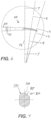
- FIG. 1 illustrates an exemplary ultrasonic surgical instrument (10). At least part of instrument (10) may be constructed and operable in accordance with at least some of the teachings of U.S. Pat. No. 5,322,055 ; U.S. Pat. No. 5,873,873 ; U.S. Pat. No. 5,980,510 ; U.S. Pat. No. 6,325,811 ; U.S. Pat. No. 6,773,444 ; U.S. Pat. No. 6,783,524 ; U.S. Pub. No. 2006/0079874 ; U.S. Pub. No. 2007/0191713 ; U.S. Pub. No. 2007/0282333 ; U.S. Pub. No.
- instrument (10) is operable to cut tissue and seal or weld tissue (e.g., a blood vessel, etc.) substantially simultaneously.
- instrument (10) may have various structural and functional similarities with the HARMONIC ACE ® Ultrasonic Shears, the HARMONIC WAVE ® Ultrasonic Shears, the HARMONIC FOCUS ® Ultrasonic Shears, and/or the HARMONIC SYNERGY ® Ultrasonic Blades. Furthermore, instrument (10) may have various structural and functional similarities with the devices taught in any of the other references that are cited.
- Instrument (10) of the present example comprises a handle assembly (20), a shaft assembly (30), and an end effector (40).
- Handle assembly (20) comprises a body (22) including a pistol grip (24) and a pair of buttons (26).
- Handle assembly (20) also includes a trigger (28) that is pivotable toward and away from pistol grip (24). It should be understood, however, that various other suitable configurations may be used, including but not limited to a scissor grip configuration.
- End effector (40) includes an ultrasonic blade (100) and a pivoting clamp arm (44).
- Clamp arm (44) is coupled with trigger (28) such that clamp arm (44) is pivotable toward ultrasonic blade (100) in response to pivoting of trigger (28) toward pistol grip (24); and such that clamp arm (44) is pivotable away from ultrasonic blade (100) in response to pivoting of trigger (28) away from pistol grip (24).
- trigger (28) Various suitable ways in which clamp arm (44) may be coupled with trigger (28) will be apparent to those of ordinary skill in the art in view of the teachings herein.
- one or more resilient members are used to bias clamp arm (44) and/or trigger (28) to the open position shown in FIG. 1 .
- An ultrasonic transducer assembly (12) extends proximally from body (22) of handle assembly (20). Transducer assembly (12) is coupled with a generator (16) via a cable (14). Transducer assembly (12) receives electrical power from generator (16) and converts that power into ultrasonic vibrations through piezoelectric principles.
- Generator (16) may include a power source and control module that is configured to provide a power profile to transducer assembly (12) that is particularly suited for the generation of ultrasonic vibrations through transducer assembly (12).
- generator (16) may comprise a GEN 300 sold by Ethicon Endo-Surgery, Inc. of Cincinnati, Ohio.
- generator (16) may be constructed in accordance with at least some of the teachings of U.S.
- generator (16) may be integrated into handle assembly (20), and that handle assembly (20) may even include a battery or other on-board power source such that cable (14) is omitted. Still other suitable forms that generator (16) may take, as well as various features and operabilities that generator (16) may provide, will be apparent to those of ordinary skill in the art in view of the teachings herein.
- Ultrasonic vibrations that are generated by transducer assembly (12) are communicated along an acoustic waveguide (150) (shown in FIGS. 11-12 ), which extends through shaft assembly (30) to reach ultrasonic blade (100). Blade (100) is thus operable to effectively cut through and seal tissue, particularly when the tissue is being clamped between clamp arm (44) and blade (100).
- waveguide (150) may be configured to amplify mechanical vibrations transmitted through waveguide (150).
- waveguide (150) may include features operable to control the gain of the longitudinal vibrations along waveguide (150) and/or features to tune the waveguide (150) to the resonant frequency of the system.
- Buttons (26) are operable to selectively activate transducer assembly (12), to thereby activate ultrasonic blade (100).
- two buttons (26) arc provided - one for activating ultrasonic blade (100) at a low power and another for activating ultrasonic blade (100) at a high power.
- any other suitable number of buttons and/or otherwise selectable power levels may be provided.
- the distal end of ultrasonic blade (100) is located at a position corresponding to an anti-node associated with resonant ultrasonic vibrations communicated through the waveguide, in order to tune the acoustic assembly to a preferred resonant frequency f o when the acoustic assembly is not loaded by tissue.
- the distal end of ultrasonic blade (100) is configured to move longitudinally in the range of, for example, approximately 10 to 500 microns peak-to-peak, and in some instances in the range of about 20 to about 200 microns at a predetermined vibratory frequency f o of, for example, 55.5 kHz.
- transducer assembly (12) of the present example When transducer assembly (12) of the present example is activated, these mechanical oscillations are transmitted through the waveguide to reach ultrasonic blade (100), thereby providing oscillation of ultrasonic blade (100) at the resonant ultrasonic frequency.
- the ultrasonic oscillation of ultrasonic blade (100) may simultaneously sever the tissue and denature the proteins in adjacent tissue cells, thereby providing a coagulative effect with relatively little thermal spread.
- clamp arm (44) may be pivoted relative to ultrasonic blade (100) to grasp and manipulate tissue without cutting or damaging the tissue.
- an electrical current may also be provided through ultrasonic blade (100) and clamp arm (44) to also cauterize the tissue. While some configurations for an acoustic transmission assembly and transducer assembly (12) have been described, still other suitable configurations for an acoustic transmission assembly and transducer assembly (12) will be apparent to one or ordinary skill in the art in view of the teachings herein. Similarly, other suitable configurations for end effector (40) will be apparent to those of ordinary skill in the art in view of the teachings herein.
- shaft assembly (30) is configured to selectively couple with transducer assembly (12).
- a torque wrench (not shown) may be included about shaft assembly (30).
- Such a torque wrench may be configured to facilitate gripping of shaft assembly (30) as shaft assembly (30) is rotated relative to transducer assembly (12) during coupling.
- such a torque wrench may be configured to provide audible and/or tactile feedback once the appropriate amount of torque as been achieved to provide a coupling of transducer assembly (12) and shaft assembly (30) at the appropriate tightness.
- a torque wrench may provide a pair of audible and tactile clicks once the appropriate level of torque/tightness has been achieved.
- Other variations of a torque wrench will be apparent to those of ordinary skill in the art in view of the teachings herein.
- a torque wrench may simply be omitted, if desired.
- shaft assembly (30) includes an articulation section enabling end effector (40) to be angularly deflected laterally away from the longitudinal axis defined by shaft assembly (30).
- an articulation section may be configured in accordance with one or more teachings of U.S. Pub. No. 2012/0078247 .
- such an articulation section may be configured in accordance with one or more teachings of U.S. Pat. App. No. 13/538,588 and/or U.S. Pat. App. No. 13/657,553 .
- some versions of shaft assembly (30) may simply lack articulation altogether.
- Shaft assembly (30) of the present example comprises a knob (32) that is operable to rotate shaft assembly (30) and end effector (40) relative to handle assembly (20), about the longitudinal axis of shaft assembly (30).
- knob (32) and rotatability of shaft assembly (30) are merely optional.
- instrument (10) may be configured in numerous other ways as will be apparent to those of ordinary skill in the art in view of the teachings herein.
- at least part of instrument (10) may be constructed and/or operable in accordance with at least some of the teachings of any of the following: U.S. Pat. No. 5,322,055 ; U.S. Pat. No. 5,873,873 ; U.S. Pat. No. 5,980,510 ; U.S. Pat. No. 6,325,811 ; U.S. Pat. No. 6,773,444 ; U.S. Pat. No. 6,783,524 ; U.S. Pub. No.
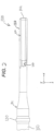
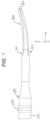
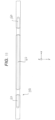
- FIGS. 2-9 show ultrasonic blade (100) of instrument (10) in greater detail.
- Ultrasonic blade (100) of the present example is in the form of a tapered multifunctional curved blade with functional asymmetries and minimized undesirable motion.
- a curved ultrasonic blade (100) may need to be properly balanced, including careful positioning of the mass along end effector (40).
- Another aspect of proper balancing may include a desire to separately balance orthogonal displacements encountered by an activated ultrasonic blade (100), which may be particularly challenging when blade (100) is curved.
- a curved ultrasonic blade (100) may be prone to fracture due to high stresses in the curved region of blade (100), particularly if blade (100) comes into contact with metal when blade (100) is in an activated state.
- a curved ultrasonic blade (100) may provide a relatively shorter active length, which may in turn limit the size of the vessel (or other tissue structure) that may be operated on by blade (100).
- Active length may be defined as the as the length from the distal end (102) of blade (100) to where the displacement is one half of the displacement at its distal end (102).
- Blade (100) of the present example accounts for the foregoing considerations.
- the curved and tapered configuration of blade (100) may provide surgical benefits such as improved surgeon visibility.
- the curve and taper may together provide a longer active length through increased speed of sound and progressive reduction in mass.
- the taper may results in a smaller surface at distal end (102), which may improve piercing/dissection capability by increasing local pressure imparted on tissue.
- Robust performance may be improved by controlling the ratio of acoustic stress to bending stress in the exposed portion of blade (100). Blade (100) may thus be less sensitive to damage from inadvertent contact with other metallic material for improved life.
- Blade (100) of the present example is positioned at the distal end of waveguide (150).
- the proximal end of waveguide (150) is coupled with transducer assembly (12).
- blade (100) and waveguide (150) together define an acoustic transmission assembly that is acoustically coupled with transducer assembly (12).
- this acoustic transmission assembly may be approximately 36 cm in length, approximately 23 cm in length, or any other suitable length.
- distal end (102) of ultrasonic blade (42) is located at a position corresponding to an anti-node associated with resonant ultrasonic vibrations communicated through waveguide (150), in order to tune the acoustic transmission assembly to a preferred resonant frequency f o when the acoustic transmission assembly is not loaded by tissue.
- Blade (100) and waveguide (150) are integrally formed in this example, though blade (100) and waveguide (150) may alternatively be formed as separate pieces that are joined together (e.g., through a threaded coupling, interference fit, welded joint, etc.).
- Blade (100) may be understood to effectively terminate proximally at the distal-most node associated with resonant ultrasonic vibrations communicated through waveguide (150). In other words, blade (100) extends from the distal-most node to the distal-most anti-node.
- distal end (102) of ultrasonic blade (100) is configured to move longitudinally (along the x-axis) in the range of, for example, approximately 10 to 500 microns peak-to-peak, and in some instances in the range of about 20 to about 200 microns, at a predetermined vibratory frequency f o of for example, 55.5 kHz.
- f o the vibratory frequency
- ultrasonic oscillation of ultrasonic blade (100) may simultaneously sever the tissue and denature the proteins in adjacent tissue cells, thereby providing a coagulative effect with relatively little thermal spread.
- Blade (100) of the present example is tapered from its proximal end toward distal end (102). Blade (100) is also curved such that the center of distal end (102) is positioned lateral to the longitudinal axis defined by waveguide (150). It should be understood that certain balance features may be required to maintain longitudinal motion substantially along the x-axis and within the x-y plane and also to separate transverse mode ranges of vibration away from the desired longitudinal mode of vibration at a resonant frequency of 55.5 kHz.
- waveguide (150) includes a series of gain steps that are configured to provide a gain of approximately 3.5, such that distal end (102) of blade (100) will vibrate along the x-axis at a maximum excursion of approximately 73.5 microns at maximum power generation (e.g., such that the excursion of transducer (150) is approximately 21.5 microns).
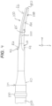
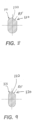
- FIGS. 7-9 shows a set of cross-sections at various locations along the length of blade (100).
- FIG. 7 shows a proximal cross-section of blade (100) along a plane that runs along an axis (PA) that is perpendicular to the longitudinal axis of waveguide (150).
- FIG. 8 shows an intermediate cross-section of blade (100) along a first plane that is obliquely oriented relative to the axis (PA).
- FIG. 9 shows a distal cross-section of blade (100) along a second plane that is obliquely oriented relative to the axis (PA).
- the width of blade (100) in the cross-section shown in FIG. 8 is between about 0.045 inches and about 0.060 inches, and more particularly between about 0.050 inches and about 0.055 inches.
- the width of blade (100) in the cross-section shown in FIG. 9 is between about 0.035 and 0.050 inches, and more particularly between about 0.040 inches and about 0.045 inches. Of course, any other suitable dimensions may be used.
- the curves and taper blade (100) are defined by simple radial cuts, as well as more complex compound radii cuts, which arc made in a base curved cylinder. These cuts define a plurality of balance features (110, 112, 114, 120).
- a first balance feature (110) is formed by a lateral concave cut having a first radius of curvature (R1).
- the first radius of curvature (R1) may be between about 0.200 inches and about 0.250 inches, and more particularly about 0.225 inches. Of course, any other suitable value may be used for the first radius of curvature (Rl).
- first balance feature (110) is defined by the first radius of curvature (R1) swept along an orthogonal x-y plane that passes through the longitudinal axis of shaft assembly (30).
- a second balance feature (112) is formed by a lateral concave cut having a second radius of curvature (R2) swept along an orthogonal x-y plane that passes through the longitudinal axis of shaft assembly (30).
- the second radius of curvature (R2) may be between about 0.250 inches and about 0.275 inches, and more particularly about 0.268 inches.
- any other suitable value may be used for the second radius of curvature (R2).
- second balance feature (112) is offset from first balance feature (110) along the length of blade (100).
- second balance feature (112) is located further distal than first balance feature (110) by between about 0.002 inches and about 0.010 inches, and more particularly about 0.005 inches.
- second balance feature (112) is defined by the second radius of curvature (R2) swept along the same orthogonal x-y plane that passes through the longitudinal axis of shaft assembly (30) as the orthogonal x-y plane associated with first balance feature (110) and first radius of curvature (R1).
- a third balance feature (114) extends circumferentially about blade (100) and is formed by a concave cut having a third radius of curvature (R3).
- the third radius of curvature (R3) may be between about 0.600 inches and about 0.700 inches, and more particularly about 0.650 inches.
- any other suitable value may be used for the third radius of curvature (R3).
- a fourth balance feature (120) is best seen in FIGS. 4 and 7-8 .
- Fourth balance feature (120) is formed as a longitudinally extending convex recess in one corner of blade (100).
- the recess of balance feature (120) is defined by a fourth radius of curvature (R4) that is swept along the x-y plane and a fifth radius of curvature (R5) that is swept along the y-z plane.
- the fourth radius of curvature (R4) may be between approximately 1.350 inches and approximately 1.425 inches, and more particularly about 1.395 inches. Alternatively, any other suitable value may be used for the fourth radius of curvature (R4).
- the x-y plane along which the fourth radius of curvature (R4) is swept is parallel to yet spaced apart from the x-y plane along which the first and second radii of curvature (R1, R2) are swept.
- the fifth radius of curvature (R5) may be between approximately 0.060 inches and approximately 0.065 inches, and more particularly about 0.062 inches. Alternatively, any other suitable value may be used for the fifth radius of curvature (R5).
- Fourth balance feature (120) may be configured to balance motion of blade (100) as described in U.S. Pat. No. 6,773,444 .
- fourth balance feature (120) presents an edge (122) that may be used to back-cut tissue and/or for other purposes.
- ultrasonic blade (100) is oriented such that edge (122) faces toward clamp arm (44). In some other versions of instrument (10) that have clamp arm (44), ultrasonic blade (100) is oriented such that edge (122) faces away from clamp arm (44).
- the lateral concave cut of second balance feature (112) transitions into a convex curve extending to distal end (102).
- This convex curve is defined by a sixth radius of curvature (R6) swept along an orthogonal x-y plane that passes through the longitudinal axis of shaft assembly (30).
- the sixth radius of curvature (R6) may be approximately 1.446 inches.
- any other suitable value may be used for the sixth radius of curvature (R6).
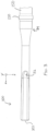
- FIG. 10 shows an exemplary alternative ultrasonic blade (200) that may be located at the distal end of waveguide (150).
- Blade (200) of this example is substantially similar to blade (100) described above and includes a distal end (202) and a plurality of balance features (210, 212, 214, 220).
- blade (100) is approximately 36 centimeters in length while blade (200) is approximately 23 centimeters in length.
- any other suitable dimensions may be used.
- the differences in the radii of curvature associated with blade (200) may be selected to account for blade (200) having a shorter length than blade (100).
- balance features (210, 212) of blade (200) are substantially identical to respective balance features (110, 112) of blade (100), including having the same radii of curvature as balance features (110, 112). While balance feature (220) of blade (200) is also similar to balance feature (120) of blade (100), balance feature (220) is defined by radii of curvature (R7, R8) that differ from the respective radii of curvature (R4, R5) that define balance feature (120). In particular, the recess of balance feature (220) is defined by a seventh radius of curvature (R7) that is swept along the x-y plane and an eighth radius of curvature (R8) that is swept along the y-z plane.
- the seventh radius of curvature (R7) may be between approximately 1.390 inches and approximately 1.500 inches, and more particularly about 1.420 inches. In some other versions, the seventh radius of curvature (R7) is approximately 1.395 inches. Alternatively, any other suitable value may be used for the seventh radius of curvature (R7). Also by way of example only, the eighth radius of curvature (R8) may be between approximately 1.000 inches and approximately 1.200 inches, and more particularly about 1.100 inches. In some other versions, the eighth radius of curvature (R8) is approximately 1.395 inches. Alternatively, any other suitable value may be used for the eighth radius of curvature (R8).
- Blade (200) of FIG. 10 also has a circumferentially extending balance feature (214) defined by a ninth radius of curvature (R9) that is approximately 1.500 inches. Alternatively, any other suitable value may be used for the ninth radius of curvature (R9).
- the lateral concave cut of balance feature (212) transitions into a convex curve extending to distal end (202). This convex curve is defined by a tenth radius of curvature (R10) swept along an orthogonal x-y plane that passes through the longitudinal axis of shaft assembly (30).
- the tenth radius of curvature (R10) may be approximately 1.395 inches.
- any other suitable value may be used for the tenth radius of curvature (R10).
- an ultrasonic blade having a length of approximately 36 cm is configured in accordance with blade (100); while an ultrasonic blade having a length of approximately 23 cm is configured in accordance with blade (200).
- the configuration of either blade (100, 200) may be combined with any other suitable ultrasonic blade length.
- FIGS. 11-12 show waveguide (150) of the present example in greater detail.
- Waveguide (150) may be flexible, semi-flexible or rigid. Waveguide (150) may also be configured to amplify the mechanical vibrations transmitted through waveguide (150) to blade (100) as is well known in the art. Waveguide (150) may further have features to control the gain of the longitudinal vibration along waveguide (150) and features to tune waveguide (150) to the resonant frequency of the system.
- waveguide (150) may have any suitable cross-sectional dimension.
- waveguide (150) may be tapered at various sections to control the gain of the longitudinal vibration.
- Waveguide (150) may, for example, have a length substantially equal to an integral number of one-half system wavelengths (n ⁇ /2).
- the waveguide (150) and blade (100) may be preferably fabricated from a solid core shaft constructed out of material, which propagates ultrasonic energy efficiently, such as titanium alloy (e.g., Ti-6A1-4V), aluminum alloys, sapphire, stainless steel or any other acoustically compatible material.
- Waveguide (150) may further include at least one radial hole or aperture (not shown) extending therethrough, substantially perpendicular to the longitudinal axis of waveguide (150). Such an aperture may be positioned at a node.
- a proximal o-ring (not shown) and distal o-ring (130) are assembled onto the acoustic transmission assembly near the ultrasonic nodes of waveguide (150), as is known in the art.
- waveguide (150) further includes balance features (160).
- Balance features (160) are formed as laterally presented flat surfaces on waveguide (150), which is otherwise cylindraceous. Balance features (160) serve to widen the transverse mode ranges away from the preferred longitudinal modes in both directions from the resonant frequency (e.g., 55.5 kHz).
- balance features (160) are spaced 180° apart on waveguide (150) and extend for a length from about 2.600 inches to about 2.800 inches, and more particularly about 2.700 inches.
- the centerline of balance features (160) is from about 7.000 to about 7.200 inches, and more particularly about 7.148 inches. Alternatively, any other suitable dimensions may be used.
- instrument (10) may include a foot pedal (not used) that provides a switch for selectively energizing transducer (12) and ultrasonic blade (100).
- the operator may use buttons (26) as switches to selectively energize transducer (12) and ultrasonic blade (100).
- Such variable resistance may make it difficult for generator (16) to detect switch closure states (e.g., when buttons (26) are depressed).
- Variability in resistance may be due to residue left on contacts of handle assembly (20) by a cleaning process; and/or due to other factors.
- Some versions of the circuitry may be significantly less susceptible to such risks. For instance, some versions of circuitry may effectively null out the effects of variable resistance in real time.
- Various examples of such circuitry are described in greater detail below; while still other examples will be apparent to those of ordinary skill in the art in view of the teachings herein.
- generator (16) comprises a GEN11 generator, manufactured and sold by Ethicon Endo-Surgery, Inc.
- Generator (16) may act as a constant-current source (e.g., at approximately +/-16mA, alternating at a low frequency, such as about 500 Hz) and determine the state of the switches (open/closed) in handle assembly (20) by measuring the voltage drop across the handswitch lines, at the face of generator (16).
- This voltage drop may include an unknown voltage drop caused by the resistance in cable (14) and/or resistance at contacts in handle assembly (20), which may change over time due to factors such as instrument rotation and changes in contact force during instrument usage, etc.
- the examples described below enable generator (16) to determine and subtract out this unknown voltage drop by measuring a known reference component in handle assembly (20) that produces a known voltage drop, in close time proximity to measuring the switch states.
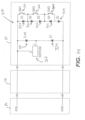
- FIG. 13 shows one merely exemplary circuit (200) that may be incorporated into instrument (10) to account for variations in resistance as described above.
- Circuit (200) includes a reference resistor (210) and an EEPROM (212) that together provide a reference feature placed on the positive leg of circuit (200). This reference feature formed by reference resistor (210) and EEPROM (212) may be read on the positive half-cycle of an interrogation signal from generator (16). It should be understood that EEPROM (212) draws such low current that EEPROM (212) will not appreciably affect the voltage drop produced by reference resistor (210).
- Circuit (200) also includes a set of switches (220), respective resistors (222), and a pair of diodes (224).
- Switches (220) are actuated by buttons (26), trigger (28), and/or other movable features in handle assembly (20). Switches (220), resistors (222), and diodes (224) are placed on the negative leg of circuit (200). Switches (220), resistors (222), and diodes (224) are thus read on the negative half-cycle of an interrogation signal from generator (16). Generator (16) is operable to determine and subtract out a voltage drop from switches (220), resistors (222), and diodes (224) based on a known voltage drop from reference resistor (210), in close time proximity to measuring the states of switches (220).
- FIG. 14 shows another merely exemplary circuit (300) that may be incorporated into instrument (10) to account for variations in resistance as described above.
- Circuit (300) includes a reference zener diode (310) and an EEPROM (312) that together provide a reference feature placed on the positive leg of circuit (300). This reference feature formed by reference zener diode (310) and EEPROM (312) may be read on the positive half-cycle of an interrogation signal from generator (16). It should be understood that EEPROM (312) draws such low current that EEPROM (312) will not appreciably affect the voltage drop produced by zener diode (310).
- Circuit (300) also includes a set of switches (320), respective diodes (322), and an additional pair of diodes (324).
- Switches (320) are actuated by buttons (26), trigger (28), and/or other movable features in handle assembly (20). Switches (320) and diodes (322, 324) are placed on the negative leg of circuit (300). Switches (320) and diodes (322, 324) are thus read on the negative half-cycle of an interrogation signal from generator (16). Generator (16) is operable to determine and subtract out a voltage drop from switches (320) and diodes (322, 324) based on a known voltage drop from reference zener diode (310), in close time proximity to measuring the states of switches (320).
- FIG. 15 shows another merely exemplary circuit (400) that may be incorporated into instrument (10) to account for variations in resistance as described above.
- Circuit (400) is substantially similar to circuit (300) described above, in that circuit (400) includes a reference zener diode (410), an EEPROM (412), switches (420), and diodes (422, 424) that are all arranged in a manner similar to the arrangement of zener diode (310), EEPROM (312), switches (320), and diodes (322, 324) of circuit (300).
- circuit (400) of this example further includes a turn-on delay circuit (430).
- Turn-on delay circuit (430) is set to approximately 1 ⁇ 4 of the interrogation signal cycle-time of generator (16), so that generator (16) sees only the reference feature (i.e., zener diode (410) and EEPROM (412)) during the first half of the negative half-cycle; and then sees switches (420), and diodes (422, 424) in parallel with the reference feature during the second half of the negative half-cycle.
- turn-on delay circuit (430) may include a Maxim MAX6895 sequencer driving a Philips PMV65XP p-channel FET.
- Other suitable configurations for turn-on-delay circuit (430) will be apparent to those of ordinary skill in the art in view of the teachings herein.
- FIG. 16 shows another merely exemplary circuit (500) that may be incorporated into instrument (10) to account for variations in resistance as described above.
- Circuit (500) is substantially similar to circuit (200) described above, in that circuit (200) includes a reference resistor (510), an EEPROM (512), switches (520), resistors (522), and diodes (524) that are all arranged in a manner similar to the arrangement of reference resistor (210), an EEPROM (212), switches (220), resistors (222), and diodes (224) of circuit (200).
- circuit (500) of this example further includes a turn-on delay circuit (530).
- Turn-on delay circuit (530) is set to approximately 1 ⁇ 4 of the interrogation signal cycle-time of generator (16), so that generator (16) sees only the reference feature (i.e., reference resistor (510) and EEPROM (512)) during the first half of the negative half-cycle; and then sees switches (520), resistors (522), and diodes (524) in parallel with the reference feature during the second half of the negative half-cycle.
- turn-on delay circuit (530) may include a Maxim MAX6895 sequencer driving a Philips PMV65XP p-channel FET.
- Other suitable configurations for turn-on-delay circuit (530) will be apparent to those of ordinary skill in the art in view of the teachings herein.
- FIG. 17 shows another merely exemplary circuit (600) that may be incorporated into instrument (10) to account for variations in resistance as described above.
- Circuit (600) is substantially similar to circuit (500) described above, in that circuit (600) includes a reference resistor (610), an EEPROM (612), switches (620), resistors (622), and diodes (624) that are all arranged in a manner similar to the arrangement of reference resistor (510), an EEPROM (512), switches (520), resistors (522), and diodes (524) of circuit (500).
- Circuit (600) also includes a turn-on delay circuit (630), which may be configured and operable just like turn-on delay circuit (530) described above.
- turn-on delay circuit (630) is inserted at the opposite end of switch (620) ladder. Such positioning of turn-on delay circuit (630) may allow the use of an output stage that employs an n-channel FET or an essentially open-drain integrated circuit (e.g., a Zetex ZSCT1555 low-voltage 555 timer).
- FIG. 18 shows exemplary input and output waveforms of turn-on delay circuits (430, 530, 630).
- signal A represents an input signal for turn-on delay circuit (430, 530, 630); while signal B represents an output signal for turn-on delay circuit (430, 530, 630).
- FIG. 19 shows another merely exemplary circuit (700) that may be incorporated into instrument (10) to account for variations in resistance as described above.
- Circuit (700) is substantially similar to circuit (400) described above, in that circuit (300) includes a reference zener diode (710), an EEPROM (712), switches (720), and diodes (722, 724) that are all arranged in a manner similar to the arrangement of zener diode (410), EEPROM (412), switches (420), and diodes (422, 424) of circuit (400).
- circuit (700) of this example further includes a toggle circuit (730) in place of turn-on delay circuit (430).
- Toggle circuit (730) of this example is a flip-flop type of circuit that is triggered by a second pulse during the negative half-cycle, and reset by the positive pulse on the positive half-cycle. While not shown, it should be understood that toggle circuit (730) may alternatively be positioned at the opposite end of the switch (720) ladder (e.g., similar to the placement of turn-on delay circuit (630) in circuit (600).
- FIG. 20 shows exemplary input and output waveforms of toggle circuit (730). In particular, signal C represents an input signal for toggle circuit (730); while signal D represents an output signal for toggle circuit (730).
- circuits (200, 300, 400, 500, 600, 700) described above are merely illustrative examples.
- Various other suitable components, features, and techniques may be used to alternately switch in a reference feature alone, and then either a switch ladder in parallel with the reference feature, or by itself.
- the number of switches (220, 320, 420, 520, 620, 720) may vary; such that more than three switches (220, 320, 420, 520, 620, 720) or less than three switches (220, 320, 420, 520, 620, 720) may be used.
- At least one or more portions of some versions of instrument (10) may be sterilized and reused. For instance, it may be desirable to reclaim and reuse electrical components within handle assembly (20), such as circuits, etc. However, it may be undesirable for other portions of handle assembly (20) to be re-used, such as the outer housing of handle assembly (20), buttons (26), etc. Thus, it may be desirable to configure handle assembly (20) such that some components within handle assembly (20) may be reclaimed and re-used; yet such that other portions of handle assembly (20) may not be reclaimed and re-used. In some settings, at least a portion of instrument (10) may be re-used after instrument (10) has been used in a surgical procedure.
- At least a portion of instrument (10) may be re-used before instrument (10) even leaves a manufacturing facility. For instance, if an instrument (10) fails a quality control test, one or more components of the instrument (10) (e.g., those that had no impact on the quality control test failure) may be reclaimed and re-used to build another instrument (10).
- handle assembly (20) may be described in greater detail below; while still other examples will be apparent to those of ordinary skill in the art in view of the teachings herein.
- At least part of the circuitry may include a flex circuit that is formed as a laminate.
- One or more regions of the outer layer of this laminate may be adhered to the housing of handle assembly (20), such that one or more layers are pulled away from the flex circuit when the housing is disassembled during a reclamation process, such that the flex circuit would be damaged. Such pulling away of layers may render the flex circuit inoperable.
- an entire outer layer of a circuit is adhered to the housing of handle assembly (20).
- only portions of the circuit near key circuit components are adhered to the housing of handle assembly (20).
- one or more components of the circuit may be adhered to the housing of handle assembly (20), without necessarily adhering the flexible laminate of a flex circuit to the housing of handle assembly (20).
- the flexible laminate of the flex circuit may be perforated or otherwise weakened, providing a controlled breakage region such that the flex circuit tears away from the adhered circuit component while the adhered circuit component remains with the housing of the handle assembly when the handle assembly portions are pulled apart during an attempted reclamation.
- one or more regions of a circuit in handle assembly (20) may be sensitive to water, alcohol, or other fluid, such that the circuit is destroyed when such regions come into contact with water, alcohol, or other fluid that may be used during an attempted reclamation.
- a circuit laminate may be configured to delaminate upon contact with water, alcohol, or other fluid.
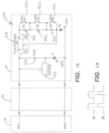
- FIGS. 21-25 show an exemplary handle housing assembly (1000) that may be incorporated into instrument (10).
- Assembly (1000) of this example includes a first housing member (1010), a second housing member (1030), and a retention member (1050).
- housing member (1010) includes a plurality of posts (1012) and a socket (1014).
- housing member (1030) includes a plurality of sockets (1032) and a post (1034). Posts (1012, 1034) are configured for insertion into corresponding sockets (1014, 1032) to secure housing members (1010, 1030) together.
- posts (1012, 1034) may be press-fit into corresponding sockets (1014, 1032), may be secured in sockets (1014, 1032) using ultrasonic welding, may be heat-staked in sockets (1014, 1032), may be adhered in sockets (1014, 1032) using adhesive, and/or may be otherwise secured relative to sockets (1014, 1032).
- housing members (1010, 1030) also include complementary tongue-and-groove features (1018, 1038).
- tongue-and-groove features (1018, 1038) are replaced with complementary shiplap features or some other kind of structures. Tongue-and-groove features (1018, 1038) may be secured together through interference fitting, ultrasonic welding, heat-staking, adhesive, etc.
- housing members (1010, 1030) each include a weakened strip (1016, 1036) in the form of a v-shaped cutout.
- Weakened strips (1016, 1036) provide reduced wall thicknesses that promote breakage along weakened strips (1016, 1036) when housing members (1010, 1030) are pulled apart.
- one or both of housing members (1010, 1030) may break its respective weakened strip (1016, 1036).
- a fragment of one housing member (1010, 1030) may remain joined to the other housing member (1010, 1030) while the rest of the fragmented housing member (1010, 1030) may be free from the other housing member (1010, 1030).
- This breakage/fragmentation may prevent re-use of both housing members (1010, 1030).
- the smaller fragment of the broken housing member (1010, 1030) may remain joined to the other housing member (1010, 1030) due to the secure relationship between tongue-and-groove features (1018, 1038), between socket (1014) and post (1034), and/or otherwise.
- Other suitable ways in which controlled breakage may be provided in housing members (1010, 1030) will be apparent to those of ordinary skill in the art in view of the teachings herein.
- retention member (1050) of the present example generally has a "Y" shape, with a first branch (1052), a second branch (1054), and a third branch (1056).
- First branch (1052) includes a bent section (1058) and a recess (1070) that terminates at an edge (1072).
- Second and third branches (1054, 1056) each have respective posts (1060).
- retention member (1050) is configured to fit in retention member features (1020, 1040) of housing members (1010, 1030).
- retention member feature (1020) of housing member (1010) comprises a pair of sockets (1022) that have a hexagonal profile.
- Sockets (1022) are configured to receive posts (1060) through an interference fitting.
- sockets (1022) may have any other suitable configuration; and ultrasonic welding, heat-staking, adhesive, etc., may also be used to secure posts (1060) in sockets (1022).
- retention member feature (1040) of housing member (1030) comprises a pair of snap latch members (1042).
- Retention member (1050) may be slid into position behind snap latch members (1042), such that snap latch members (1042) may assist in maintaining the positioning of retention member (1050) relative to housing member (1030).
- bent section (1058) of retention member (1050) passes between and in front of snap latch members (1042) when branches (1054, 1056) are positioned behind snap latch members (1042).
- one or more switch assemblies are positioned behind buttons (26), and include switching circuitry that is responsive to actuation of buttons (26).
- Recess (1070) is sized to receive a portion of such a switch assembly.
- a switch assembly may be slid between bent section (1058) of first branch (1052) and snap latch members (1042), with the switch assembly being received in recess (1070).
- Snap latch members (1042) assist in holding the switch assembly in position relative to housing member (1030).
- a pair of ribs (1043) defined in housing member (1010) also hold the switch assembly against housing member (1030).
- one outer edge of the switch assembly is retained by snap latch members (1042) while the opposite outer edge of the switch assembly, which is seated in recess (1070), is retained by retention member (1050). Since retention member (1050) is secured to housing member (1010), it should be understood that retention member (1050) and snap latch members (1042) will exert opposing forces on the outer edges of the switch assembly as housing members (1010, 1030) are pulled apart. These opposing surfaces on the switch assembly may sever/break the switch assembly (e.g., by shearing) or otherwise render it in operable. Thus, if a person attempts to disassembly handle assembly (1000) by pulling housing members (1010, 1030) apart, doing so will also destroy the switch assembly that is located behind buttons (26).
- the switch assembly may comprise any suitable components such as rigid circuit boards, flexible circuits, wires, conventional switches, etc. In some instances, edge (1072) is sharp to facilitate severing of the switch assembly.
- a switch assembly may be otherwise retained relative to housing member (1030).
- at least part of the switch assembly may be welded to housing member (1030) (e.g., using spin welding, ultrasonic welding, heat-staking, adhesives, etc.).
- a secondary retention feature may be overlaid about recess (1070) of retention member (1050).
- the switch assembly may be adhered to housing member (1030). Other suitable ways in which a switch assembly may be secured will be apparent to those of ordinary skill in the art in view of the teachings herein.
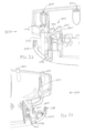
- FIG. 26 shows another exemplary handle housing assembly (1100) that may be incorporated into instrument (10).
- Assembly (1100) of this example includes a first housing member (1110) and a second housing member (1130).
- Housing member (1110) includes a plurality of posts (1112) and a socket (1114).
- Housing member (1130) includes a plurality of sockets (1132) and a post (1134).
- Posts (1112, 1134) are configured for insertion into corresponding sockets (1114, 1132) to secure housing members (1110, 1130) together.
- posts (1112, 1134) may be press-fit into corresponding sockets (1114, 1132), may be secured in sockets (1114, 1132) using ultrasonic welding, may be heat-staked in sockets (1114, 1132), may be adhered in sockets (1114, 1132) using adhesive, and/or may be otherwise secured relative to sockets (1114, 1132).
- Housing member (1110) includes an integral retention feature (1150) that comprises a pair of prongs (1152).
- Prongs (1152) define a gap configured to receive a portion of a switch assembly, which may include switching circuitry that is responsive to actuation of buttons (26).
- An adhesive may be used to adhere the switch assembly to prongs (1152).
- the switch assembly may be retained in retention feature (1150). It should be understood that, due to the adhesion of the switch assembly in retention feature (1150), a person who is assembling several housing assemblies (1100) may be able to quickly identify housing assembly (1100) as one that had already been assembled and perhaps later disassembled. This may prompt the person to discard the housing assembly (1100) as scrap.
- an adhesive may be used to adhere the switch assembly to an adjacent region of housing member (1130).
- housing assembly (1100) is disassembled by pulling housing members (1110, 1130) apart, the switch assembly may be ripped apart and thereby rendered inoperable.
- a person who is assembling several housing assemblies (1100) may be able to quickly identify housing assembly (1100) as one that had already been assembled and later disassembled.
- FIG. 27 shows an example where a hole (1200) may be drilled in a housing member (1010, 1110) at a location corresponding to post (1034, 1134) and socket (1014, 1114), thereby effectively decoupling post (1034, 1134) and socket (1014, 1114).
- FIG. 27 shows an example where a hole (1200) may be drilled in a housing member (1010, 1110) at a location corresponding to post (1034, 1134) and socket (1014, 1114), thereby effectively decoupling post (1034, 1134) and socket (1014, 1114).
- housing members (1010, 1030, 1110, 1130) may be drilled in numerous other locations, including those associated with posts (1012, 1112) and sockets (1032, 1132).
- the drilled holes may facilitate separation of housing member (1010, 1110) from housing member (1030, 1130) with minimal force, may substantially maintain structural integrity of housing members (1010, 1110, 1030, 1 130), and/or may minimize damage to components within housing members (1010, 1110, 1030, 1130).
- the drilled hole may be filled in, covered, or otherwise dealt with.
- FIGS. 29-30 show an exemplary ultrasonic blade assembly (1300) comprising an ultrasonic blade (1310) disposed in a tube (1320).
- Ultrasonic blade (1310) is positioned such that a distal end (1312) of blade (1310) is exposed relative to tube (1320).
- Tube (1320) has an inner diameter that is substantially greater than the outer diameter of blade (1310), such that a cylindraceous gap is defined between the inner diameter of tube (1320) and the outer diameter of blade (1310).
- An annular overmold (1330) is positioned about the exterior of blade (1310) to support blade (1310) relative to tube (1320).
- overmold (1330) may be formed of a plastic material or an elastomeric material.
- Overmold (1330) may be located at a longitudinal position corresponding to a node associated with resonant ultrasonic vibrations communicated through blade (1310). The positioning and/or properties of overmold (1330) provide substantial acoustic isolation of tube (1320) relative to blade (1310). While one overmold (1330) is shown, it should be understood that several ovcrmolds may be used. It should also be understood that features other than overmold (1330) may be used. By way of example only, one or more o-rings located at nodes may be used instead of overmold (1330).
- Tube (1320) includes a distally directed tab (1322) formed by a "U"-shaped cut in tube (1320). As best seen in FIG. 30 , tab (1322) is directed inwardly and distally within tube (1320). In the present example, tab (1322) does not contact ultrasonic blade (1310). In some other versions, tab (1322) contacts ultrasonic blade (1310) at a node associated with resonant ultrasonic vibrations communicated through blade (1320). Tab (1322) is resilient such that tab (1322) deflects out of the way when blade (1310) and overmold (1330) are inserted distally through tube (1320) during assembly of ultrasonic blade assembly (1300); yet tab (1322) returns back to the position shown in FIG.
- tab (1322) will tear through overmold (1330) or otherwise destroy overmold (1330). To the extent that someone attempts to later re-use blade (1310) and overmold (1330), the destroyed overmold (1330) would cause the rebuilt ultrasonic blade assembly (1300) to fail a leak test.
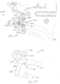
- transducer assembly (12) may be supported within handle assembly (20) by a connector housing that permits transducer assembly (12) to rotate relative to handle assembly (20), about the longitudinal axis defined by transducer assembly (12).
- FIGS. 31 -33 show an example of such a connector housing (1400) along with exemplary features that may be used to couple connector housing (1400) to handle assembly (20).
- connector housing (1400) of this example includes a retention boss (1410) that defines an opening (1412).
- One housing half of the handle includes a retention clip (1420); while another housing half of the handle includes a pair of retention flanges (1430).
- retention clip (1420) includes a pair of barbed arms (1422).
- Barbed arms (1422) are configured to fit through opening (1412) of retention boss (1410) and thereby provide a snap fit between connector housing (1400) and the associated housing half of the handle, as shown in the transition from FIG. 31 to FIG. 32 .
- Flanges (1430) arc configured to partially encompass connector housing (1400) and thereby restrict movement of connecting housing (1400) to some degree; yet still permit connector housing (1400) to float within the handle assembly to some degree.
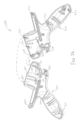
- FIG. 34 shows an example where a first clamshell half (1510) and a second clamshell half (1520) join together to encompass a connector housing (1500) that is similar to connector housing (1400) described above.
- Joined halves (1510, 1520) may couple with handle assembly (20) through gripper pins, adhesive, ultrasonic welding, some other form of welding, or in any other suitable fashion.
- Joined halves (1510, 1520) may or may not move relative to handle assembly (20). However, joined halves (1510, 1520) may enable connector housing (1500) to float relative to joined halves (1510, 1520) as needed.
- a silicone member may be interposed between connector housing (1500) and handle assembly (20) instead of joined halves (1510, 1520).
- Such a silicone member may substantially retain connector housing (1500) within handle assembly (20) yet still permit some degree of movement (i.e., floating) of connector housing (1500) relative to handle assembly (20).
- Other suitable ways in which a connector housing may be coupled with a handle assembly will be apparent to those of ordinary skill in the art in view of the teachings herein.
- These connector housing coupling features may be used m conjunction with any of the features described above to provide a way of recognizing a used switch assembly or shroud.
- Versions of the devices described above may have application in conventional medical treatments and procedures conducted by a medical professional, as well as application in robotic-assisted medical treatments and procedures.
- various teachings herein may be readily incorporated into a robotic surgical system such as the DAVINCI TM system by Intuitive Surgical, Inc., of Sunnyvale, California.
- Versions described above may be designed to be disposed of after a single use, or they can be designed to be used multiple times. Versions may, in either or both cases, be reconditioned for reuse after at least one use. Reconditioning may include any combination of the steps of disassembly of the device, followed by cleaning or replacement of particular pieces, and subsequent reassembly. In particular, some versions of the device may be disassembled, and any number of the particular pieces or parts of the device may be selectively replaced or removed in any combination. Upon cleaning and/or replacement of particular parts, some versions of the device may be reassembled for subsequent use either at a reconditioning facility, or by a user immediately prior to a procedure.
- reconditioning of a device may utilize a variety of techniques for disassembly, cleaning/replacement, and reassembly. Use of such techniques, and the resulting reconditioned device, are all within the scope of the present application.
- versions described herein may be sterilized before and/or after a procedure.
- the device is placed in a closed and sealed container, such as a plastic or TYVEK bag.
- the container and device may then be placed in a field of radiation that can penetrate the container, such as gamma radiation, x-rays, or high-energy electrons.
- the radiation may kill bacteria on the device and in the container.
- the sterilized device may then be stored in the sterile container for later use.
- a device may also be sterilized using any other technique known in the art, including but not limited to beta or gamma radiation, ethylene oxide, or steam.
Applications Claiming Priority (5)
| Application Number | Priority Date | Filing Date | Title |
|---|---|---|---|
| US201261640227P | 2012-04-30 | 2012-04-30 | |
| US201261722986P | 2012-11-06 | 2012-11-06 | |
| US13/868,336 US10238416B2 (en) | 2012-04-30 | 2013-04-23 | Ultrasonic device for cutting and coagulating |
| EP13722906.8A EP2844158B1 (en) | 2012-04-30 | 2013-04-26 | Ultrasonic device for cutting and coagulating |
| PCT/US2013/038396 WO2013165842A1 (en) | 2012-04-30 | 2013-04-26 | Ultrasonic device for cutting and coagulating |
Related Parent Applications (2)
| Application Number | Title | Priority Date | Filing Date |
|---|---|---|---|
| EP13722906.8A Division EP2844158B1 (en) | 2012-04-30 | 2013-04-26 | Ultrasonic device for cutting and coagulating |
| EP13722906.8A Division-Into EP2844158B1 (en) | 2012-04-30 | 2013-04-26 | Ultrasonic device for cutting and coagulating |
Publications (2)
| Publication Number | Publication Date |
|---|---|
| EP3919008A1 EP3919008A1 (en) | 2021-12-08 |
| EP3919008B1 true EP3919008B1 (en) | 2024-03-27 |
Family
ID=49477937
Family Applications (2)
| Application Number | Title | Priority Date | Filing Date |
|---|---|---|---|
| EP21187407.8A Active EP3919008B1 (en) | 2012-04-30 | 2013-04-26 | Ultrasonic device for cutting and coagulating |
| EP13722906.8A Active EP2844158B1 (en) | 2012-04-30 | 2013-04-26 | Ultrasonic device for cutting and coagulating |
Family Applications After (1)
| Application Number | Title | Priority Date | Filing Date |
|---|---|---|---|
| EP13722906.8A Active EP2844158B1 (en) | 2012-04-30 | 2013-04-26 | Ultrasonic device for cutting and coagulating |
Country Status (12)
| Country | Link |
|---|---|
| US (2) | US10238416B2 (pt) |
| EP (2) | EP3919008B1 (pt) |
| JP (1) | JP6702721B2 (pt) |
| KR (1) | KR102198444B1 (pt) |
| CN (1) | CN104271051B (pt) |
| AU (2) | AU2013256686A1 (pt) |
| BR (1) | BR112014027043B1 (pt) |
| CA (1) | CA2871945C (pt) |
| IN (1) | IN2014DN08803A (pt) |
| MX (1) | MX366565B (pt) |
| RU (1) | RU2669023C2 (pt) |
| WO (1) | WO2013165842A1 (pt) |
Families Citing this family (40)
| Publication number | Priority date | Publication date | Assignee | Title |
|---|---|---|---|---|
| US10238416B2 (en) * | 2012-04-30 | 2019-03-26 | Ethicon Llc | Ultrasonic device for cutting and coagulating |
| US10172636B2 (en) | 2013-09-17 | 2019-01-08 | Ethicon Llc | Articulation features for ultrasonic surgical instrument |
| US9861381B2 (en) * | 2013-11-12 | 2018-01-09 | Ethicon Llc | Removable battery casing for surgical instrument |
| US9763674B2 (en) * | 2013-12-26 | 2017-09-19 | Ethicon Llc | Ultrasonic bone cutting instrument |
| US10258363B2 (en) | 2014-04-22 | 2019-04-16 | Ethicon Llc | Method of operating an articulating ultrasonic surgical instrument |
| US10667835B2 (en) | 2014-04-22 | 2020-06-02 | Ethicon Llc | Ultrasonic surgical instrument with end effector having restricted articulation |
| KR20160107492A (ko) | 2015-03-04 | 2016-09-19 | 김용호 | 초음파 절삭기의 냉각 장치 및 그에 의한 초음파 절삭기의 냉각 방법 |
| US10029125B2 (en) | 2015-04-16 | 2018-07-24 | Ethicon Llc | Ultrasonic surgical instrument with articulation joint having integral stiffening members |
| US10226274B2 (en) | 2015-04-16 | 2019-03-12 | Ethicon Llc | Ultrasonic surgical instrument with articulation joint having plurality of locking positions |
| US10342567B2 (en) | 2015-04-16 | 2019-07-09 | Ethicon Llc | Ultrasonic surgical instrument with opposing thread drive for end effector articulation |
| US20160302818A1 (en) | 2015-04-16 | 2016-10-20 | Ethicon Endo-Surgery, Llc | Ultrasonic surgical instrument with movable rigidizing member |
| US20160302819A1 (en) | 2015-04-16 | 2016-10-20 | Ethicon Endo-Surgery, Llc | Ultrasonic surgical instrument with articulating end effector having a curved blade |
| US11020140B2 (en) * | 2015-06-17 | 2021-06-01 | Cilag Gmbh International | Ultrasonic surgical blade for use with ultrasonic surgical instruments |
| CN105310746B (zh) * | 2015-07-22 | 2018-04-24 | 以诺康医疗科技(苏州)有限公司 | 一种同时提高切割和止血效果的超声手术刀 |
| US10893914B2 (en) | 2015-10-19 | 2021-01-19 | Ethicon Llc | Surgical instrument with dual mode end effector and modular clamp arm assembly |
| US10314607B2 (en) * | 2015-12-21 | 2019-06-11 | Ethicon Llc | Ultrasonic surgical instrument with tubular acoustic waveguide segment |
| US10835255B2 (en) * | 2016-02-10 | 2020-11-17 | Covidien Lp | Adapter assemblies for interconnecting electromechanical handle assemblies and surgical loading units |
| WO2017168515A1 (ja) * | 2016-03-28 | 2017-10-05 | オリンパス株式会社 | 関節用超音波処置具、及びその処置方法 |
| US10492819B2 (en) | 2016-04-01 | 2019-12-03 | Ethicon Llc | Surgical instrument with dual mode articulation drive |
| US10507034B2 (en) | 2016-04-04 | 2019-12-17 | Ethicon Llc | Surgical instrument with motorized articulation drive in shaft rotation knob |
| US10743850B2 (en) | 2016-04-04 | 2020-08-18 | Ethicon Llc | Surgical instrument with locking articulation drive wheel |
| US10575836B2 (en) * | 2016-04-04 | 2020-03-03 | Ethicon Llc | Surgical instrument with selectively locked articulation assembly |
| US10405876B2 (en) | 2016-04-05 | 2019-09-10 | Ethicon Llc | Articulation joint for surgical instrument |
| WO2018087841A1 (ja) * | 2016-11-09 | 2018-05-17 | オリンパス株式会社 | 振動伝達部材及び超音波処置具 |
| US10575917B2 (en) * | 2016-12-14 | 2020-03-03 | Ethicon Llc | Ultrasonic surgical instrument with integral torque wrench and transverse engagement |
| US11129661B2 (en) * | 2017-05-22 | 2021-09-28 | Cilag Gmbh International | Combination ultrasonic and electrosurgical system having EEPROM and ASIC components |
| JP6828162B2 (ja) * | 2017-07-21 | 2021-02-10 | オリンパス株式会社 | 超音波処置具のブレード、及び、超音波処置具 |
| CN107595368B (zh) | 2017-10-19 | 2024-04-30 | 以诺康医疗科技(苏州)有限公司 | 一种超声波手术刀头、刀杆及超声波手术刀 |
| KR102012840B1 (ko) * | 2017-12-29 | 2019-08-21 | (의료)길의료재단 | 고온분무 흡입 초음파 절삭기 |
| US11540856B2 (en) | 2018-05-31 | 2023-01-03 | Covidien Lp | Methods and systems for ultrasonic vessel sealing |
| CN112135573A (zh) | 2018-07-09 | 2020-12-25 | 奥林巴斯株式会社 | 医疗设备的再制造方法 |
| CN110811770B (zh) * | 2018-08-14 | 2023-04-07 | 北京锐诺医疗技术有限公司 | 一种超声刀传导杆及超声刀 |
| WO2020190534A1 (en) | 2019-03-15 | 2020-09-24 | Oshkosh Corporation | Scissor lift with offset pins |
| CN114040719A (zh) * | 2019-04-17 | 2022-02-11 | 柯惠有限合伙公司 | 用于超声手术器械的超声波导和刀片以及其制造方法 |
| US20200337760A1 (en) * | 2019-04-26 | 2020-10-29 | Covidien Lp | Single-use surgical instrument |
| KR102128489B1 (ko) | 2019-12-21 | 2020-06-30 | 주식회사 메타바이오메드 | 에너지 수집이 가능한 무선형 초음파 수술기 |
| USD956222S1 (en) | 2020-08-21 | 2022-06-28 | Stryker European Operations Limited | Surgical bur assembly |
| KR102600134B1 (ko) * | 2021-07-08 | 2023-11-08 | 김용훈 | 외과 수술용 드릴 |
| USD1024324S1 (en) * | 2021-08-11 | 2024-04-23 | Ezisurg Medical Co., Ltd. | Handle for surgical instrument |
| CN115770086A (zh) * | 2022-11-30 | 2023-03-10 | 苏州英途康医疗科技有限公司 | 电动施夹器 |
Family Cites Families (31)
| Publication number | Priority date | Publication date | Assignee | Title |
|---|---|---|---|---|
| US4531524A (en) * | 1982-12-27 | 1985-07-30 | Rdm International, Inc. | Circuit apparatus and method for electrothermal treatment of cancer eye |
| US5322055B1 (en) * | 1993-01-27 | 1997-10-14 | Ultracision Inc | Clamp coagulator/cutting system for ultrasonic surgical instruments |
| US6066979A (en) * | 1996-09-23 | 2000-05-23 | Eldec Corporation | Solid-state high voltage linear regulator circuit |
| US5980510A (en) | 1997-10-10 | 1999-11-09 | Ethicon Endo-Surgery, Inc. | Ultrasonic clamp coagulator apparatus having improved clamp arm pivot mount |
| US5873873A (en) * | 1997-10-10 | 1999-02-23 | Ethicon Endo-Surgery, Inc. | Ultrasonic clamp coagulator apparatus having improved clamp mechanism |
| US6309400B2 (en) * | 1998-06-29 | 2001-10-30 | Ethicon Endo-Surgery, Inc. | Curved ultrasonic blade having a trapezoidal cross section |
| US6666875B1 (en) | 1999-03-05 | 2003-12-23 | Olympus Optical Co., Ltd. | Surgical apparatus permitting recharge of battery-driven surgical instrument in noncontact state |
| US6325811B1 (en) * | 1999-10-05 | 2001-12-04 | Ethicon Endo-Surgery, Inc. | Blades with functional balance asymmetries for use with ultrasonic surgical instruments |
| US6783524B2 (en) | 2001-04-19 | 2004-08-31 | Intuitive Surgical, Inc. | Robotic surgical tool with ultrasound cauterizing and cutting instrument |
| US6918758B2 (en) * | 2003-03-25 | 2005-07-19 | John Jiin Chung Yang | Childproof safety disposable lighter |
| EP1802245B8 (en) | 2004-10-08 | 2016-09-28 | Ethicon Endo-Surgery, LLC | Ultrasonic surgical instrument |
| GB2423931B (en) * | 2005-03-03 | 2009-08-26 | Michael John Radley Young | Ultrasonic cutting tool |
| US8016843B2 (en) | 2005-09-09 | 2011-09-13 | Alcon Research Ltd | Ultrasonic knife |
| US20070191713A1 (en) * | 2005-10-14 | 2007-08-16 | Eichmann Stephen E | Ultrasonic device for cutting and coagulating |
| US8574252B2 (en) | 2006-06-01 | 2013-11-05 | Ethicon Endo-Surgery, Inc. | Ultrasonic blade support |
| US9693792B2 (en) * | 2006-10-18 | 2017-07-04 | Misonix, Incorporated | Ultrasonic treatment method and apparatus with active pain suppression |
| BRPI0806674A2 (pt) | 2007-01-16 | 2014-05-13 | Ethicon Endo Surgery Inc | Dispositivo ultrassônico para corte e coagulação |
| US8057498B2 (en) | 2007-11-30 | 2011-11-15 | Ethicon Endo-Surgery, Inc. | Ultrasonic surgical instrument blades |
| US20090069830A1 (en) * | 2007-06-07 | 2009-03-12 | Piezo Resonance Innovations, Inc. | Eye surgical tool |
| CN101883531B (zh) | 2007-10-05 | 2014-07-02 | 伊西康内外科公司 | 人体工程学外科手术器械 |
| US9107690B2 (en) * | 2007-12-03 | 2015-08-18 | Covidien Ag | Battery-powered hand-held ultrasonic surgical cautery cutting device |
| EP2361042B1 (en) | 2008-09-12 | 2016-11-30 | Ethicon Endo-Surgery, Inc. | Ultrasonic device for fingertip control |
| US8461744B2 (en) | 2009-07-15 | 2013-06-11 | Ethicon Endo-Surgery, Inc. | Rotating transducer mount for ultrasonic surgical instruments |
| US9168054B2 (en) * | 2009-10-09 | 2015-10-27 | Ethicon Endo-Surgery, Inc. | Surgical generator for ultrasonic and electrosurgical devices |
| US8986302B2 (en) * | 2009-10-09 | 2015-03-24 | Ethicon Endo-Surgery, Inc. | Surgical generator for ultrasonic and electrosurgical devices |
| US9402682B2 (en) | 2010-09-24 | 2016-08-02 | Ethicon Endo-Surgery, Llc | Articulation joint features for articulating surgical device |
| US9381058B2 (en) | 2010-11-05 | 2016-07-05 | Ethicon Endo-Surgery, Llc | Recharge system for medical devices |
| US20120116265A1 (en) | 2010-11-05 | 2012-05-10 | Houser Kevin L | Surgical instrument with charging devices |
| US10238416B2 (en) * | 2012-04-30 | 2019-03-26 | Ethicon Llc | Ultrasonic device for cutting and coagulating |
| US9393037B2 (en) | 2012-06-29 | 2016-07-19 | Ethicon Endo-Surgery, Llc | Surgical instruments with articulating shafts |
| US9095367B2 (en) | 2012-10-22 | 2015-08-04 | Ethicon Endo-Surgery, Inc. | Flexible harmonic waveguides/blades for surgical instruments |
-
2013
- 2013-04-23 US US13/868,336 patent/US10238416B2/en active Active
- 2013-04-26 KR KR1020147033350A patent/KR102198444B1/ko active IP Right Grant
- 2013-04-26 CN CN201380022660.3A patent/CN104271051B/zh active Active
- 2013-04-26 EP EP21187407.8A patent/EP3919008B1/en active Active
- 2013-04-26 EP EP13722906.8A patent/EP2844158B1/en active Active
- 2013-04-26 AU AU2013256686A patent/AU2013256686A1/en not_active Abandoned
- 2013-04-26 MX MX2014013199A patent/MX366565B/es active IP Right Grant
- 2013-04-26 CA CA2871945A patent/CA2871945C/en active Active
- 2013-04-26 JP JP2015510347A patent/JP6702721B2/ja active Active
- 2013-04-26 IN IN8803DEN2014 patent/IN2014DN08803A/en unknown
- 2013-04-26 RU RU2014148146A patent/RU2669023C2/ru active
- 2013-04-26 BR BR112014027043-0A patent/BR112014027043B1/pt active IP Right Grant
- 2013-04-26 WO PCT/US2013/038396 patent/WO2013165842A1/en active Application Filing
-
2017
- 2017-10-11 AU AU2017245348A patent/AU2017245348B2/en not_active Ceased
-
2019
- 2019-02-12 US US16/273,214 patent/US11529164B2/en active Active
Also Published As
| Publication number | Publication date |
|---|---|
| CA2871945A1 (en) | 2013-11-07 |
| US20190247082A1 (en) | 2019-08-15 |
| US11529164B2 (en) | 2022-12-20 |
| EP3919008A1 (en) | 2021-12-08 |
| JP6702721B2 (ja) | 2020-06-03 |
| EP2844158B1 (en) | 2021-11-03 |
| RU2669023C2 (ru) | 2018-10-05 |
| CN104271051A (zh) | 2015-01-07 |
| RU2014148146A (ru) | 2016-06-20 |
| KR102198444B1 (ko) | 2021-01-06 |
| MX366565B (es) | 2019-07-11 |
| AU2013256686A1 (en) | 2014-10-23 |
| AU2017245348A1 (en) | 2017-11-02 |
| JP2015516231A (ja) | 2015-06-11 |
| CN104271051B (zh) | 2017-09-08 |
| US20130289592A1 (en) | 2013-10-31 |
| WO2013165842A1 (en) | 2013-11-07 |
| BR112014027043A2 (pt) | 2017-06-27 |
| BR112014027043B1 (pt) | 2022-02-08 |
| EP2844158A1 (en) | 2015-03-11 |
| KR20150008153A (ko) | 2015-01-21 |
| IN2014DN08803A (pt) | 2015-05-22 |
| US10238416B2 (en) | 2019-03-26 |
| CA2871945C (en) | 2020-10-27 |
| AU2017245348B2 (en) | 2018-12-20 |
| MX2014013199A (es) | 2014-12-08 |
Similar Documents
| Publication | Publication Date | Title |
|---|---|---|
| US11529164B2 (en) | Ultrasonic device for cutting and coagulating | |
| EP3364896B1 (en) | Surgical instrument with dual mode end effector and modular clamp arm assembly | |
| US9861381B2 (en) | Removable battery casing for surgical instrument | |
| CN107106196B (zh) | 超声刀重叠注塑 | |
| EP2581053A1 (en) | Surgical instrument with ultrasonic waveguide defining a fluid lumen | |
| US20200179000A1 (en) | Ultrasonic surgical instrument with clamp arm deflection feature | |
| WO2017112473A1 (en) | Ultrasonic surgical instrument with tubular acoustic waveguide segment | |
| EP3457960B1 (en) | Passive dissection features for ultrasonic surgical instrument | |
| US10413314B2 (en) | Ultrasonic surgical instrument with activation member pair and slidable cover | |
| CN113905677A (zh) | 刀接地机构和另选的销轴设计 |
Legal Events
| Date | Code | Title | Description |
|---|---|---|---|
| PUAI | Public reference made under article 153(3) epc to a published international application that has entered the european phase |
Free format text: ORIGINAL CODE: 0009012 |
|
| STAA | Information on the status of an ep patent application or granted ep patent |
Free format text: STATUS: THE APPLICATION HAS BEEN PUBLISHED |
|
| AC | Divisional application: reference to earlier application |
Ref document number: 2844158 Country of ref document: EP Kind code of ref document: P |
|
| AK | Designated contracting states |
Kind code of ref document: A1 Designated state(s): AL AT BE BG CH CY CZ DE DK EE ES FI FR GB GR HR HU IE IS IT LI LT LU LV MC MK MT NL NO PL PT RO RS SE SI SK SM TR |
|
| B565 | Issuance of search results under rule 164(2) epc |
Effective date: 20211013 |
|
| STAA | Information on the status of an ep patent application or granted ep patent |
Free format text: STATUS: REQUEST FOR EXAMINATION WAS MADE |
|
| 17P | Request for examination filed |
Effective date: 20220608 |
|
| RBV | Designated contracting states (corrected) |
Designated state(s): AL AT BE BG CH CY CZ DE DK EE ES FI FR GB GR HR HU IE IS IT LI LT LU LV MC MK MT NL NO PL PT RO RS SE SI SK SM TR |
|
| GRAP | Despatch of communication of intention to grant a patent |
Free format text: ORIGINAL CODE: EPIDOSNIGR1 |
|
| STAA | Information on the status of an ep patent application or granted ep patent |
Free format text: STATUS: GRANT OF PATENT IS INTENDED |
|
| INTG | Intention to grant announced |
Effective date: 20230510 |
|
| GRAJ | Information related to disapproval of communication of intention to grant by the applicant or resumption of examination proceedings by the epo deleted |
Free format text: ORIGINAL CODE: EPIDOSDIGR1 |
|
| STAA | Information on the status of an ep patent application or granted ep patent |
Free format text: STATUS: REQUEST FOR EXAMINATION WAS MADE |
|
| GRAP | Despatch of communication of intention to grant a patent |
Free format text: ORIGINAL CODE: EPIDOSNIGR1 |
|
| STAA | Information on the status of an ep patent application or granted ep patent |
Free format text: STATUS: GRANT OF PATENT IS INTENDED |
|
| INTC | Intention to grant announced (deleted) | ||
| INTG | Intention to grant announced |
Effective date: 20231011 |
|
| GRAS | Grant fee paid |
Free format text: ORIGINAL CODE: EPIDOSNIGR3 |
|
| GRAA | (expected) grant |
Free format text: ORIGINAL CODE: 0009210 |
|
| STAA | Information on the status of an ep patent application or granted ep patent |
Free format text: STATUS: THE PATENT HAS BEEN GRANTED |
|
| AC | Divisional application: reference to earlier application |
Ref document number: 2844158 Country of ref document: EP Kind code of ref document: P |
|
| AK | Designated contracting states |
Kind code of ref document: B1 Designated state(s): AL AT BE BG CH CY CZ DE DK EE ES FI FR GB GR HR HU IE IS IT LI LT LU LV MC MK MT NL NO PL PT RO RS SE SI SK SM TR |
|
| REG | Reference to a national code |
Ref country code: GB Ref legal event code: FG4D |
|
| REG | Reference to a national code |
Ref country code: CH Ref legal event code: EP |
|
| REG | Reference to a national code |
Ref country code: DE Ref legal event code: R096 Ref document number: 602013085509 Country of ref document: DE |