EP3918889B1 - Verbindungsanordnung zum verbinden einer stromschiene mit einem gehäuse - Google Patents
Verbindungsanordnung zum verbinden einer stromschiene mit einem gehäuse Download PDFInfo
- Publication number
- EP3918889B1 EP3918889B1 EP20701743.5A EP20701743A EP3918889B1 EP 3918889 B1 EP3918889 B1 EP 3918889B1 EP 20701743 A EP20701743 A EP 20701743A EP 3918889 B1 EP3918889 B1 EP 3918889B1
- Authority
- EP
- European Patent Office
- Prior art keywords
- connection arrangement
- electrically insulating
- busbar
- housing
- fastening
- Prior art date
- Legal status (The legal status is an assumption and is not a legal conclusion. Google has not performed a legal analysis and makes no representation as to the accuracy of the status listed.)
- Active
Links
Images


Classifications
-
- H—ELECTRICITY
- H05—ELECTRIC TECHNIQUES NOT OTHERWISE PROVIDED FOR
- H05K—PRINTED CIRCUITS; CASINGS OR CONSTRUCTIONAL DETAILS OF ELECTRIC APPARATUS; MANUFACTURE OF ASSEMBLAGES OF ELECTRICAL COMPONENTS
- H05K7/00—Constructional details common to different types of electric apparatus
- H05K7/14—Mounting supporting structure in casing or on frame or rack
- H05K7/1422—Printed circuit boards receptacles, e.g. stacked structures, electronic circuit modules or box like frames
- H05K7/1427—Housings
- H05K7/1432—Housings specially adapted for power drive units or power converters
- H05K7/14329—Housings specially adapted for power drive units or power converters specially adapted for the configuration of power bus bars
-
- H—ELECTRICITY
- H02—GENERATION; CONVERSION OR DISTRIBUTION OF ELECTRIC POWER
- H02G—INSTALLATION OF ELECTRIC CABLES OR LINES, OR OF COMBINED OPTICAL AND ELECTRIC CABLES OR LINES
- H02G5/00—Installations of bus-bars
- H02G5/06—Totally-enclosed installations, e.g. in metal casings
-
- H—ELECTRICITY
- H02—GENERATION; CONVERSION OR DISTRIBUTION OF ELECTRIC POWER
- H02G—INSTALLATION OF ELECTRIC CABLES OR LINES, OR OF COMBINED OPTICAL AND ELECTRIC CABLES OR LINES
- H02G5/00—Installations of bus-bars
- H02G5/10—Cooling
-
- H—ELECTRICITY
- H05—ELECTRIC TECHNIQUES NOT OTHERWISE PROVIDED FOR
- H05K—PRINTED CIRCUITS; CASINGS OR CONSTRUCTIONAL DETAILS OF ELECTRIC APPARATUS; MANUFACTURE OF ASSEMBLAGES OF ELECTRICAL COMPONENTS
- H05K7/00—Constructional details common to different types of electric apparatus
- H05K7/20—Modifications to facilitate cooling, ventilating, or heating
- H05K7/2089—Modifications to facilitate cooling, ventilating, or heating for power electronics, e.g. for inverters for controlling motor
- H05K7/209—Heat transfer by conduction from internal heat source to heat radiating structure
-
- H—ELECTRICITY
- H02—GENERATION; CONVERSION OR DISTRIBUTION OF ELECTRIC POWER
- H02G—INSTALLATION OF ELECTRIC CABLES OR LINES, OR OF COMBINED OPTICAL AND ELECTRIC CABLES OR LINES
- H02G5/00—Installations of bus-bars
- H02G5/02—Open installations
- H02G5/025—Supporting structures
Definitions
- the invention relates to a connection arrangement for connecting a busbar to a housing according to the preamble of patent claim 1.
- a generic connection arrangement is out EP 2 871 921 B1 known.
- a housing for electrical components comprising an electrically insulating body, a housing body and a bus bar is described.
- the housing body and the electrically insulating body are connected to one another in one piece and the busbar is embedded in the electrically insulating body.
- the claimed connection arrangement is therefore not designed to be detachable from one another in a non-destructive manner, which represents a significant disadvantage for maintenance and/or repair work as well as for recycling.
- a power electronics submodule with a switching device is described there.
- a substrate of the switching device comprises a first and a second DC voltage circuit board, to which a first and a second DC voltage connection element are connected.
- the substrate further includes a printed AC conductor to which an AC connector is connected.
- connection arrangement is from the US 2017/201 083 A1 known.
- the power converter described there has busbars that have a dual function. They cool the electronic switches and conduct electricity to them from the electronic switches.
- the large tab of the housing is soldered or otherwise attached directly to the power rail.
- the object of the invention is to create a connection arrangement that conducts heat well and is easy to assemble.
- One area of application of the invention is, for example, applications in the automotive sector, in particular applications in electromobility.
- busbar in the sense of this invention also includes other electrically conductive components.
- connection arrangement comprises a busbar, at least one wall of a housing, at least one electrically insulating element and at least one fastening element used to connect the busbar to the housing.
- connection arrangement has at least one fastening element for connection to the wall of the housing and in that the at least one electrically insulating element is made of a thermally highly conductive material.
- a good thermally conductive material for example, has a conductivity of around 1.5 W/(m K) or more.
- a detachable connection arrangement is particularly advantageous in the case of maintenance and/or repair work and also during recycling.
- Simultaneously designing the electrically insulating element from a material with good thermal conductivity enables the heat generated in the busbar to be dissipated towards the wall of the housing and thus prevents overheating of the busbar, at least one electrical component arranged in the housing and other electrical components arranged therein.
- connection arrangement has at least two fastening elements, with at least a first fastening element connecting the busbar, optionally the electrical component, and the electrically insulating element to one another and a second fastening element connecting the electrically insulating element to the wall of the housing.
- the busbar is fastened in two steps, whereby first the electrically insulating element is connected to the wall of the housing and then the busbar is connected to the electrically insulating element.
- connection arrangement has at least one continuous fastening element.
- the busbar and the electrically insulating element as well as optionally also an electrical component connected to the busbar can be connected to the wall of the housing at the same time, that is to say by means of the at least one continuous fastening element.
- the connecting arrangement comprises at least one screw and/or at least one threaded rod and/or at least one rivet and/or at least one press bolt, as well as at least one nut and/or at least one threaded sleeve and/or at least one press bushing associated therewith.
- the connection arrangement can also include an adhesive connection.
- a combination of several of the above-mentioned fastening elements can also be used.
- the connection arrangement is also designed to be separable from the housing for recycling purposes.
- connection arrangement has a metal element that can be connected to the electrically insulating element.
- the electrically insulating and thermally highly conductive element can also be formed from an oxidic or non-oxidic ceramic material.
- the electrically insulating element is designed as a sleeve which insulates the busbar and optionally an electrical component connected to it from the continuous fastening element.
- the connection arrangement according to the invention also advantageously enables compensation for thermal expansion of the busbar.
- several electrically insulating elements can also be arranged.
- a plastic disk or a ceramic plate can also form part of the connection arrangement.
- the electrically insulating element is simultaneously designed as a fastening element or as part of a fastening element.
- the electrically insulating element has at least one bore.
- This at least one hole can be designed as a blind hole or as a through hole between two opposite sides of the electrically insulating element. Both the through hole and the blind hole can be designed with or without countersinking.
- At least one wall of the housing is designed as a cooling plate.
- At least one blind hole for fastening the connection arrangement to the housing can be formed on an inside of the wall.
- the blind hole can be designed as a thread to hold a screw or threaded rod or with a smooth surface to hold a rivet or press-in bolt.
- the connection arrangement can therefore be screwed or attached to the wall of the housing by pressing or gluing. Due to the attachment of the connection arrangement to the cooling plate, heat can be transported from the busbar and/or from the electrical component to the housing, whereby both active and passive cooling can be implemented.
- connection arrangement according to the invention also makes it possible to reduce the conductor cross sections of the busbar, which leads to a reduction in the overall weight of the equipped housing.
- the housing is formed in particular by a housing of a device for energy distribution and/or energy conversion, which is sometimes also referred to in the professional world as a power distribution unit (PDU) or power distribution module (PDM), and at least one DC/DC Includes converters and other high-voltage components.
- PDU power distribution unit
- PDM power distribution module
- the Figure 1 shows a first example of a housing 10 with a connection arrangement 20 with a continuous fastening element 60.
- An electrical component 30 is arranged above a busbar 40 and this in turn is arranged above an electrically insulating element 50, which forms the shape of a plastic block. Since the temperature of the busbar can rise to 120 ° C during operation, the invention provides that the electrically insulating element 50 is designed to be very thermally conductive.
- a good thermally conductive material for example, has a conductivity of around 1.5 W/(mK) or more.
- the electrically insulating and thermally highly conductive element 50 is in all of them Figures 1 to 5 illustrated embodiments of a plastic block, a plastic disk or a plastic layer preferably sprayed onto the busbar 40, for example made of polypropylene (PP), polyphthalamide (PPA), polyamide (in particular PA 6, PA 66 or PA 12), thermoplastic copolyesters (COPE), polyphenylene Sulfide (PPS), Liquid Crystal Polymer (LCP), Thermoplastic Elastomers (TPE), Polycarbonate/Acrylonitrile Butadiene Styrene (PC/ABS Blend), Polyetheretherketone (PEEK), Polyetherimides (PEI) or Polybutylene Terephthalate (PBT).
- PP polypropylene
- PPA polyphthalamide
- PA 6 PA 66 or PA 12
- COPE thermoplastic copolyesters
- PPS polyphenylene Sulfide
- LCP Liquid Crystal Polymer
- TPE Polycarbonate/A
- the electrically insulating and thermally highly conductive element 50 can alternatively or in addition to this also be formed from an oxidic or non-oxidic ceramic material.
- the electrical component 30, the busbar 40 and the electrically insulating element 50 have a hole 33 or 43 or 53, which is each designed as a through hole.
- a sleeve 54 made of electrically insulating material is inserted through the holes in a mounting direction R 33 and 43, whereby a collar 56 of the sleeve 54 is brought into contact with a first side 31 of the electrical component 30 and a lower edge 57 of the sleeve 54 is flush with a second side 42 of the busbar 40.
- the sleeve 54 advantageously also enables thermal expansion of the busbar 40 to be compensated for at the same time.
- the electrically insulating element 50 has, on a first side 51, a shaft 59 which encloses the bore 53 and is arranged within the sleeve 54.
- a length L59 of the shaft 59 corresponds to a length L54 of the sleeve 54.
- the lower edge 57 of the sleeve 54 therefore also rests on the first side 51 of the electrically insulating element 50.
- the continuous fastening element 60 which in the Figure 1 is formed by a first fastening means 61A, can be passed through a hole 55 in the sleeve 54 and the through hole 53 of the electrically insulating element 50.
- the first fastening means 61A is formed by a threaded rod. In alternative exemplary embodiments, this can also be formed by a screw or a rivet or a press bolt.
- the first fastening means 61A designed as a threaded rod, is passed through the through hole 53 of the electrically insulating element 50 by means of screwing.
- a receptacle or an attachment for a tool is formed at an upper end 65 of the first fastening means 61A, which is in Fig. 1 Example shown is formed by a slot for a screwdriver.
- the first fastening means 61A can also be fastened in the electrically insulating element 50 by pressing in, gluing or by injection molding, as in Fig. 3 shown.
- the first fastening means 61A is inserted into a blind hole 13, which is arranged on an inside 12 of the wall 11.
- the blind hole 13 is designed as a threaded hole in the exemplary embodiment shown, so that a thread 64 of the first fastening means 61A can be fastened in the blind hole 13.
- a second side 52 of the electrically insulating element 50 is thus pressed against the inside 12 of the wall 11, which according to the invention is designed as a cooling plate.
- the upper end 65 of the first fastening means 61A is firmly screwed by means of a second fastening means 61B designed in the manner of a nut.
- the collar 56 of the sleeve 54 is pressed onto the first side 31 of the electrical component 30 and a second side 32 of the electrical component 30 is pressed onto a first side 41 of the busbar 40.
- the heat transport thus made possible between the electrical component 30, the busbar 40 and the wall 11 of the housing 10 results in both active and passive cooling. As a result, overheating of the electrical components 30 and 40 arranged in the housing 10 can be avoided.
- the electrically insulating element 50 is designed as a plastic disk and/or as a ceramic plate made of one or more of the materials already described above.
- the electrical component 30, the busbar 40 and the electrically insulating element 50 have holes 33 or 43 or 53 designed as through holes.
- the sleeve 54 is passed through the holes 33 and 43 in the assembly direction R, whereby the collar 56 of the sleeve 54 is brought into contact with the first side 31 of the electrical component 30 and the lower edge 57 of the sleeve 54 with the second side 42 of the busbar 40 is flush.
- the sleeve 54 also advantageously enables thermal expansion of the busbar 40 to be compensated for.
- the busbar 40 can rest over a large area on the electrically insulating element 50 and thus the heat generated in the busbar 40 via the electrically insulating over a larger area than in the first exemplary embodiment shown Derive element 50 towards the wall 11 of the housing 10, which is designed as a cooling plate.
- an electrically insulating element 50 designed as a plate a smaller overall height of the connection arrangement 20 can also be achieved.
- connection arrangement 20 to the wall 11 of the housing 10 also takes place in the exemplary embodiment shown Fig. 2 by means of a continuous fastening element 60, the fastening means 61A of which is designed as a rivet and the blind hole 13 in the wall 11 is thus designed with a smooth surface.
- the connecting arrangement 20 can therefore be connected to the wall 11 via positive locking in the form of cold rivets or via frictional locking in the form of warm rivets. Alternatively, fastening using a screw connection is also possible.
- connection arrangement 20 with at least two fastening elements 61 and 62 is shown.
- the first fastening element 61 is formed by a first fastening means 61A and a second fastening means 61B and the fastening element 62 is formed by a metal element 80.
- the first fastening means 61A passes through the bores 33 and 43 of the electrical component 30 and the busbar 40 and engages in a bore 53A formed on the first side 51 of the electrically insulating, highly heat-conducting element 50. This is designed as a blind hole in which a second fastening means 61B is arranged.
- the first fastening means 61A can be used as Screw or be designed as a threaded rod or as a press bolt.
- the fastening means 61B which serves as a counterpart, can be designed, for example, as a nut or as a threaded sleeve or as a press bushing. If it is at least partially made of plastic - for example a plastic casing - the fastening means 61B can also advantageously enable compensation for thermal expansion of the busbar 40 in this exemplary embodiment.
- the metal element 80 is arranged in a second bore 53B on the second side 52 of the electrically insulating element 50, which is also designed as a blind hole.
- the metal element 80 can be fastened in the electrically insulating element 50, for example by injection molding or screwing in or by gluing.
- the electrically insulating, highly heat-conducting element 50 is designed as a plastic block in the exemplary embodiment shown.
- connection arrangement 20 with at least two fastening elements 61 and 62, no sleeve 54 is necessary as an insulating element, which insulates the electrical component 30 and the busbar 40 from the fastening element 60.
- the direct contact between the continuous fastening element 60 and the wall 11 of the housing 10 is not present in this connection arrangement 20 because the electrically insulating, highly heat-conducting element 50 in this case has no through hole and thus the busbar 40 and the fastening element 60 or 61A opposite the wall 11 is completely insulated.
- connection arrangement 20 is in Figure 3 connected to the wall 11 of the housing 10 by screwing a thread 84 of the metal element 80 into the blind hole 13 provided with a threaded hole.
- the screw connection can also be replaced by a press connection or an adhesive connection.
- connection arrangement 20 with at least two fastening elements 61 and 62 is shown.
- the connection of the The connection arrangement 20 with the wall 11 of the housing 10 takes place in two steps.
- the electrically insulating element 50 is attached to the wall 11 of the housing by means of at least two second connecting elements 62.
- these are guided into two holes 53B provided in the electrically insulating element 50, the upper area of which is larger in diameter than a through hole in the lower area.
- the two second connecting elements 62 are preferably designed as screws.
- the connection of electrical component 30 and busbar 40 by means of the first fastening element 61 takes place analogously Figure 3 .
- the exemplary embodiment described is a third variant of fastening by means of at least two fastening elements 61 and 62.
- the first fastening element 61 is in Figure 5 designed as a fastening means 61A, for example with a Christmas tree profile for pressing into a correspondingly shaped receptacle.
- the electrically insulating element 50 is designed as a sleeve 54 with a first sleeve half 54A and a second sleeve half 54B.
- the sleeve halves 54A and 54B can be connected to one another at a butt joint 58, which can be done, for example, by gluing or welding.
- the sleeve 54 can also be made in one piece and pressed into the blind hole 13 in the wall 11.
- the inner surface of the sleeve 54 is preferably designed with a Christmas tree profile that runs in the opposite direction to the Christmas tree profile of the first fastening element 61, so that the profiles interlock with each other in a form-fitting manner when pressed in.
- other forms of fastening are also possible here, such as screwing into a nut formed in the sleeve 54 or received in it.
- the sleeve 54 is in accordance with the exemplary embodiment shown Fig. 5 simultaneously formed as an electrically insulating element 50 and as a second fastening element 62.
- An adhesive 90 connects the second side 52 of the electrically insulating element 50 to the inside 12 of the wall 11 of the housing 10.
- the sleeve 54 also advantageously enables thermal expansion of the busbar to be compensated for in this exemplary embodiment.
- the electrically insulating, highly heat-conducting element 50 can also be formed by a layer made of plastic and / or ceramic, which can, for example, partially or completely surround the busbar 50 outside of its intended contact areas as an overmolding.
Landscapes
- Engineering & Computer Science (AREA)
- Microelectronics & Electronic Packaging (AREA)
- Physics & Mathematics (AREA)
- Thermal Sciences (AREA)
- Connections By Means Of Piercing Elements, Nuts, Or Screws (AREA)
- Connector Housings Or Holding Contact Members (AREA)
Description
- Die Erfindung betrifft eine Verbindungsanordnung zum Verbinden einer Stromschiene mit einem Gehäuse gemäß dem Oberbegriff des Patentanspruchs 1.
- Eine gattungsgemäße Verbindungsanordnung ist aus
EP 2 871 921 B1 bekannt. Darin wird ein Gehäuse für elektrische Komponenten, umfassend einen elektrisch isolierenden Körper, einen Gehäusekörper und eine Sammelschiene beschrieben. Dabei sind der Gehäusekörper und der elektrisch isolierende Körper einstückig miteinander verbunden und die Sammelschiene ist in den elektrisch isolierenden Körper eingebettet. Die beanspruchte Verbindungsanordnung ist somit nicht zerstörungsfrei voneinander lösbar ausgebildet, was bei Wartungs- und/oder Reparaturarbeiten sowie für das Recycling einen wesentlichen Nachteil darstellt. - Eine weitere Verbindungsanordnung ist aus der
US 2019 / 020 285 A1 bekannt. Dort wird ein Leistungselektronik-Submodul mit einer Schalteinrichtung beschrieben. Ein Substrat der Schalteinrichtung umfasst eine erste und eine zweite Gleichspannungsleiterplatte, mit denen ein erstes und ein zweites Gleichspannungsanschlusselement verbunden sind. Das Substrat enthält ferner einen gedruckten Wechselspannungsleiter, mit dem ein Wechselspannungsanschlusselement verbunden ist. - Eine weitere Verbindungsanordnung ist aus der
US 2017 / 201 083 A1 bekannt. Der dort beschriebene Leistungswandler weist Stromschienen auf, die eine Doppelfunktion haben. Sie kühlen die elektronischen Schalter und leiten Strom zu der von den elektronischen Schaltern. Bei den elektronischen Schaltern, die in einem Gehäuse untergebracht sind, ist die große Lasche des Gehäuses direkt an die Stromschiene gelötet oder anderweitig befestigt. - Aufgabe der Erfindung ist es, eine gut wärmeleitende und leicht montierbare Verbindungsanordnung zu schaffen.
- Diese Aufgabe wird erfindungsgemäß durch eine Verbindungsanordnung mit den Merkmalen des Anspruchs 1 gelöst. Vorteilhafte Ausgestaltungen der Erfindung sind in den Unteransprüchen angegeben.
- Ein Einsatzgebiet der Erfindung sind beispielsweise Anwendungen im Automobilbereich, insbesondere Anwendungen in der Elektromobilität.
- Mit der vorliegenden Erfindung ist es möglich, eine gut wärmeleitende, reparaturfreundliche Verbindungsanordnung zur Befestigung einer Stromschiene und optional weiterer elektrischer, elektromechanischer oder elektronischer Komponenten - wie beispielsweise Sicherungen oder Schütze - an einer Wand eines Gehäuses zu schaffen. Vom Begriff "Stromschiene" im Sinne dieser Erfindung werden auch andere elektrisch leitende Bauteile umfasst.
- Die erfindungsgemäße Verbindungsanordnung umfasst eine Stromschiene, wenigstens eine Wand eines Gehäuses, wenigstens ein elektrisch isolierendes Element und wenigstens ein zum Verbinden der Stromschiene mit dem Gehäuse dienendes Befestigungselement.
- Die Erfindung zeichnet sich dadurch aus, dass die Verbindungsanordnung wenigstens ein Befestigungselement zur Verbindung mit der Wand des Gehäuses aufweist und dass das wenigstens eine elektrisch isolierende Element aus einem thermisch gut leitenden Werkstoff ausgebildet ist. Ein gut thermisch leitender Werkstoff hat beispielsweise eine Leitfähigkeit ab etwa 1,5 W/(m·K) oder mehr.
- Eine lösbare Verbindungsanordnung ist besonders im Falle von Wartungs- und/oder Reparaturarbeiten und auch beim Recycling von großem Vorteil. Das elektrisch isolierende Element gleichzeitig aus einem thermisch gut leitfähigen Werkstoff zu gestalten, ermöglicht eine Wärmeableitung der in der Stromschiene erzeugten Wärme hin zur Wand des Gehäuses und verhindert so ein Überhitzen der Stromschiene, wenigstens eines im Gehäuse angeordneten elektrischen Bauteils und weiterer darin angeordneter elektrischer Komponenten.
- Erfindungsgemäß weist die Verbindungsanordnung wenigstens zwei Befestigungselemente auf, wobei wenigstens ein erstes Befestigungselement die Stromschiene, optional das elektrische Bauteil, und das elektrisch isolierende Element miteinander verbindet und ein zweites Befestigungselement das elektrisch isolierende Element mit der Wand des Gehäuses verbindet. In diesem Fall erfolgt die Befestigung der Stromschiene in zwei Schritten, wobei zuerst das elektrisch isolierende Element mit der Wand des Gehäuses und dann die Stromschiene mit dem elektrisch isolierenden Element verbunden wird.
- Gemäß einer vorteilhaften Weiterbildung der Erfindung weist die Verbindungsanordnung wenigstens ein durchgehendes Befestigungselement auf. Dabei sind die Stromschiene und das elektrisch isolierende Element sowie optional auch ein mit der Stromschiene in Verbindung stehendes elektrisches Bauteil gleichzeitig, das heißt mittels des wenigstens einen durchgehenden Befestigungselements, mit der Wand des Gehäuses verbindbar.
- In vorteilhaften Ausführungsbeispielen umfasst die Verbindungsanordnung dabei wenigstens eine Schraube und/oder wenigstens eine Gewindestange und/oder wenigstens einen Niet und/oder wenigstens einen Pressbolzen, sowie jeweils dazugehörend wenigstens eine Mutter und/oder wenigstens eine Gewindehülse und/oder wenigstens eine Pressbuchse. Des Weiteren kann die Verbindungsanordnung auch eine Klebeverbindung umfassen. In alternativen Ausführungsbeispielen kann auch eine Kombination mehrerer der vorstehend genannten Befestigungselemente Verwendung finden. Besonders vorteilhaft ist die Verbindungsanordnung zu Recyclingzwecken auch wieder trennbar vom Gehäuse gestaltet.
- In einem weiterhin vorteilhaften Ausführungsbeispiel weist die Verbindungsanordnung ein mit dem elektrisch isolierenden Element verbindbares Metallelement auf.
- In einer vorteilhaften Weiterbildung der erfindungsgemäßen Befestigungsanordnung ist das elektrisch isolierende und thermisch sehr gut leitende Element von einem Kunststoffblock, einer Kunststoffscheibe oder einer bevorzugt auf die Stromschiene aufgespritzten Kunststoffschicht, beispielsweise aus Polypropylen (PP), Polyphthalamid (PPA), Polyamid (insbesondere PA 6, PA 66 oder PA 12), Thermoplastische Copolyester (COPE), Polyphenylen Sulfid (PPS), Liquid Crystal Polymer (LCP), Thermoplastische Elastomere (TPE), Polycarbonate/Acrylnitril Butadien Styrol (PC/ABS-Blend), Polyetheretherketon (PEEK), Polyetherimide (PEI) oder Polybutylenterephthalat (PBT) gebildet. Diesen Kunststoffen werden zur Verbesserung der thermischen Leitfähigkeit bevorzugt keramische und/oder mineralische Füllstoffe hinzugefügt, wie beispielsweise Aluminiumoxid oder Bornitrid. Beispiele für besonders geeignete Materialien für das elektrisch isolierende und thermisch sehr gut leitende Element sind:
- Laticonther® 82 CP1 /800, PA12 mit thermischer Leitfähigkeit von 9.5 W/(m*K),
- Laticonther® 62 CP6-V0HF1, PA 6 mit thermischer Leitfähigkeit von 4 W/(m*K),
- Laticonther® 52 CP1/60, PPH mit thermischer Leitfähigkeit 6 W/(m*K),
- CoolPoly® D5506, Thermally Conductive Liquid Crystalline Polymer (LCP) mit 10 W/(m*K) oder
- CoolPoly® D3612, Thermally Conductive Polyamide (PA) mit 6 W/(m*K).
- Das elektrisch isolierende und thermisch sehr gut leitende Element kann alternativ dazu auch von einem oxidischen oder nichtoxidischen Keramikmaterial gebildet werden.
- Besonders geeignet sind hierbei beispielsweise von den oxidischen Keramikwerkstoffen:
- Aluminiumoxid,
- ZTA-Werkstoffe (Zirconia Toughened Alumina) oder
- ATZ-Werkstoffe (Alumina Toughened Zirconia).
- Besonders geeignet sind hierbei beispielsweise von den nichtoxidischen Keramikwerkstoffen:
- Aluminiumnitrid,
- Siliciumcarbid oder
- Siliziumnitrid.
- In einer weiteren vorteilhaften Ausführungsform ist das elektrisch isolierende Element als Hülse ausgebildet, die die Stromschiene und optional ein mit dieser verbundenes elektrische Bauteil gegenüber dem durchgehenden Befestigungselement isoliert. Die erfindungsgemäße Verbindungsanordnung ermöglicht dadurch zusätzlich auch vorteilhaft einen Ausgleich von Wärmedehnungen der Stromschiene. In alternativen Ausführungsbeispielen können auch mehrere elektrisch isolierende Elemente angeordnet sein. So kann beispielsweise zusätzlich zur Hülse auch eine Kunststoffscheibe oder eine Keramikplatte einen Teil der Verbindungsanordnung bilden.
- In einer besonders vorteilhaften Weiterbildung ist das elektrisch isolierende Element gleichzeitig als Befestigungselement oder als Teil eines Befestigungselements ausgebildet.
- Das elektrisch isolierende Element weist in einer weiterhin besonders vorteilhaften Weiterbildung wenigstens eine Bohrung auf. Diese wenigstens eine Bohrung kann dabei als Sackloch oder als Durchgangsbohrung zwischen zwei gegenüberliegenden Seiten des elektrisch isolierenden Elements ausgebildet sein. Sowohl die Durchgangsbohrung als auch die Sackbohrung kann dabei mit oder ohne Senkung ausgebildet sein.
- Vorteilhaft ist die wenigstens eine Wand des Gehäuses als Kühlplatte ausgebildet ist. An einer Innenseite der Wand kann dabei wenigstens ein Sackloch zur Befestigung der Verbindungsanordnung am Gehäuse ausgebildet sein. Dabei kann das Sackloch als Gewinde zur Aufnahme einer Schraube oder Gewindestange oder mit einer glatten Oberfläche zur Aufnahme eines Niets oder Einpressbolzens ausgebildet sein. Die Verbindungsanordnung ist somit abhängig vom jeweiligen Ausführungsbeispiel schraubbar oder durch Verpressen oder durch Verkleben an der Wand des Gehäuses befestigbar. Aufgrund der Befestigung der Verbindungsanordnung an der Kühlplatte kann somit ein Wärmetransport von der Stromschiene und/oder vom elektrischen Bauteil zum Gehäuse erfolgen, wodurch sowohl eine aktive als auch eine passive Kühlung realisierbar ist.
- Zudem ist durch die Wärmeabfuhr über die erfindungsgemäße Verbindungsanordnung auch eine Reduzierung der Leiterquerschnitte der Stromschiene möglich, was zu einer Reduzierung des Gesamtgewichts des bestückten Gehäuses führt.
- Das Gehäuse wird insbesondere von einem Gehäuse einer Vorrichtung zur Energieverteilung und/oder zur Energieumwandlung gebildet, die in der Fachwelt manchmal auch als Power-Distribution-Unit (PDU) oder Power Distribution Module (PDM) bezeichnet wird, und wenigstens einen DC/DC-Wandler und weitere Hochvolt-Komponenten umfasst.
- Nachfolgend sind Ausführungsbeispiele der Erfindung unter Bezugnahme auf die Zeichnungen näher erläutert. Es zeigt:
- Fig. 1
- ein erstes Beispiel einer Verbindungsanordnung mit einem durchgehenden Befestigungselement;
- Fig. 2
- ein zweites Beispiel einer Verbindungsanordnung mit einem durchgehenden Befestigungselement;
- Fig. 3
- ein erstes erfindungsgemäßes Ausführungsbeispiel einer Verbindungsanordnung mit wenigstens zwei Befestigungselementen;
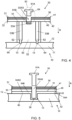
- Fig. 4
- ein zweites erfindungsgemäßes Ausführungsbeispiel einer Verbindungsanordnung mit wenigstens zwei Befestigungselementen und
- Fig. 5
- ein drittes erfindungsgemäßes Ausführungsbeispiel eines Gehäuses mit einer Verbindungsanordnung mit wenigstens zwei Befestigungselementen .
- Die
Figur 1 zeigt ein erstes Beispiel eines Gehäuses 10 mit einer Verbindungsanordnung 20 mit einem durchgehenden Befestigungselement 60. Ein elektrisches Bauelement 30 ist dabei oberhalb einer Stromschiene 40 angeordnet und diese wiederum oberhalb eines elektrisch isolierenden Elements 50, welches die Form eines Kunststoffblocks bildet. Da im Betrieb die Temperatur der Stromschiene bis auf 120°C ansteigen kann, ist erfindungsgemäß vorgesehen, dass das elektrisch isolierende Element 50 thermisch sehr gut leitend ausgebildet ist. Ein gut thermisch leitender Werkstoff hat beispielsweise eine Leitfähigkeit ab etwa 1,5 W/(m-K) oder mehr. - Das elektrisch isolierende und thermisch sehr gut leitende Element 50 ist in allen in den
Figuren 1 bis 5 dargestellten Ausführungsbeispielen von einem Kunststoffblock, einer Kunststoffscheibe oder einer bevorzugt auf die Stromschiene 40 aufgespritzten Kunststoffschicht, beispielsweise aus Polypropylen (PP), Polyphthalamid (PPA), Polyamid (insbesondere PA 6, PA 66 oder PA 12), Thermoplastische Copolyester (COPE), Polyphenylen Sulfid (PPS), Liquid Crystal Polymer (LCP), Thermoplastische Elastomere (TPE), Polycarbonate/Acrylnitril Butadien Styrol (PC/ABS-Blend), Polyetheretherketon (PEEK), Polyetherimide (PEI) oder Polybutylenterephthalat (PBT) gebildet. - Diesen Kunststoffen werden zur Verbesserung der thermischen Leitfähigkeit bevorzugt keramische und/oder mineralische Füllstoffe hinzugefügt, wie beispielsweise Aluminiumoxid oder Bornitrid. Beispiele für besonders geeignete Materialien für das elektrisch isolierende und thermisch sehr gut leitende Element 50 sind:
- Laticonther® 82 CP1/800, PA12 mit thermischer Leitfähigkeit von 9.5 W/(m*K),
- Laticonther® 62 CP6-V0HF1, PA 6 mit thermischer Leitfähigkeit von 4 W/(m*K),
- Laticonther® 52 CP1/60, PPH mit thermischer Leitfähigkeit 6 W/(m*K),
- CoolPoly® D5506, Thermally Conductive Liquid Crystalline Polymer (LCP) mit 10 W/(m*K) oder
- CoolPoly® D3612, Thermally Conductive Polyamide (PA) mit 6 W/(m*K).
- Das elektrisch isolierende und thermisch sehr gut leitende Element 50 kann alternativ oder ergänzend dazu auch von einem oxidischen oder nichtoxidischen Keramikmaterial gebildet werden.
- Besonders geeignet sind hierbei beispielsweise von den oxidischen Keramikwerkstoffen:
- Aluminiumoxid,
- ZTA-Werkstoffe (Zirconia Toughened Alumina) oder
- ATZ-Werkstoffe (Alumina Toughened Zirconia).
- Besonders geeignet sind von den nichtoxidischen Keramikwerkstoffen beispielsweise:
- Aluminiumnitrid,
- Siliciumcarbid oder
- Siliziumnitrid.
- Das elektrische Bauelement 30, die Stromschiene 40 sowie das elektrisch isolierende Element 50 weisen eine Bohrung 33 bzw. 43 bzw. 53 auf, die jeweils als Durchgangsbohrung ausgebildet ist. Bei der Montage wird eine Hülse 54 aus elektrisch isolierenden Material in einer Montagerichtung R durch die Bohrungen 33 und 43 hindurchgeführt, wodurch ein Kragen 56 der Hülse 54 auf einer ersten Seite 31 des elektrischen Bauteils 30 zur Anlage gebracht wird und ein unterer Rand 57 der Hülse 54 mit einer zweiten Seite 42 der Stromschiene 40 bündig abschließt. Die Hülse 54 ermöglicht vorteilhaft auch gleichzeitig einen Ausgleich von Wärmedehnungen der Stromschiene 40.
- Das elektrisch isolierende Element 50 weist an einer ersten Seite 51 einen die Bohrung 53 umschließenden Schaft 59 auf, welcher innerhalb der Hülse 54 angeordnet ist. Dabei entspricht eine Länge L59 des Schafts 59 einer Länge L54 der Hülse 54. Somit liegt der untere Rand 57 der Hülse 54 ebenfalls auf der ersten Seite 51 des elektrisch isolierenden Elements 50 auf.
- Das durchgehende Befestigungselement 60, welches in der
Figur 1 von einem ersten Befestigungsmittel 61A gebildet ist, kann durch eine Bohrung 55 in der Hülse 54 und die Durchgangsbohrung 53 des elektrisch isolierenden Elements 50 hindurchgeführt werden. - Im gezeigten Beispiel ist das erste Befestigungsmittel 61A von einer Gewindestange gebildet. In alternativen Ausführungsbeispielen kann dieses auch von einer Schraube oder einem Niet oder einem Pressbolzen gebildet sein.
- Die Befestigung des in
Fig. 1 als Gewindestange ausgebildeten ersten Befestigungsmittels 61A durch die Durchgangsbohrung 53 des elektrisch isolierenden Elements 50 erfolgt im gezeigten Ausführungsbeispiel mittels Verschrauben. Hierzu ist an einem oberen Ende 65 ersten Befestigungsmittels 61A eine Aufnahme oder ein Ansatz für ein Werkzeug ausgebildet, der im inFig. 1 gezeigten Beispiel von einem Schlitz für einen Schraubendreher gebildet wird. - Alternativ ist das erste Befestigungsmittel 61A auch durch Einpressen, Kleben oder durch Umspritzen im elektrisch isolierenden Element 50 befestigbar, wie in
Fig. 3 gezeigt. - Zur Befestigung der Verbindungsanordnung 20 an einer Wand 11 des Gehäuses 10 wird das erste Befestigungsmittel 61A in ein Sackloch 13 eingeführt, welches an einer Innenseite 12 der Wand 11 angeordnet ist. Das Sackloch 13 ist im gezeigten Ausführungsbeispiel als Gewindebohrung ausgebildet, so dass ein Gewinde 64 des ersten Befestigungsmittels 61A im Sackloch 13 befestigbar ist. Eine zweite Seite 52 des elektrisch isolierenden Elements 50 wird so an die Innenseite 12 der Wand 11 angepresst, welche erfindungsgemäß als Kühlplatte ausgebildet ist.
- Um eine zuverlässige Verbindung der Verbindungsanordnung 20 an der Wand 11 des Gehäuses 12 zu gewährleisten, wird das obere Ende 65 des ersten Befestigungsmittels 61A mittels eines nach Art einer Mutter ausgebildeten zweiten Befestigungsmittels 61B fest verschraubt. Dadurch wird der Kragen 56 der Hülse 54 auf die erste Seite 31 des elektrischen Bauteils 30 und eine zweite Seite 32 des elektrischen Bauteils 30 auf eine erste Seite 41 der Stromschiene 40 gedrückt.
- Durch den so ermöglichten Wärmetransport zwischen dem elektrischen Bauteil 30, der Stromschiene 40 und der Wand 11 des Gehäuses 10 erfolgt sowohl eine aktive als auch passive Kühlung. Dadurch kann ein Überhitzen der im Gehäuse 10 angeordneten elektrischen Komponenten 30 bzw. 40 vermieden werden.
- Im in der
Figur 2 gezeigten zweiten Beispiel einer Verbindungsanordnung 20 mit einem durchgehenden Befestigungselement 60 ist das elektrisch isolierende Element 50 als Kunststoffscheibe und/oder als Keramikplatte aus einem oder mehreren der bereits vorstehend beschriebenen Werkstoffe ausgebildet. - Auch in diesem Beispiel weisen das elektrische Bauelement 30, die Stromschiene 40 sowie das elektrisch isolierende Element 50 als Durchgangsbohrungen ausgebildete Bohrungen 33 bzw. 43 bzw. 53 auf. Bei der Montage wird die Hülse 54 in Montagerichtung R durch die Bohrungen 33 und 43 hindurchgeführt, wodurch der Kragen 56 der Hülse 54 auf der ersten Seite 31 des elektrischen Bauteils 30 zur Anlage gebracht wird und der untere Rand 57 der Hülse 54 mit der zweiten Seite 42 der Stromschiene 40 bündig abschließt. Die Hülse 54 ermöglicht zusätzlich auch vorteilhaft einen Ausgleich von Wärmedehnungen der Stromschiene 40.
- Da das elektrisch isolierende Element 50 im gezeigten Beispiel in Form einer Platte ausgebildet ist, kann die Stromschiene 40 großflächig auf dem elektrisch isolierenden Element 50 aufliegen und somit über eine größere Fläche als im ersten gezeigten Ausführungsbeispiel die in der Stromschiene 40 erzeugte Wärme über das elektrisch isolierende Element 50 hin zu der als Kühlplatte ausgebildeten Wand 11 des Gehäuses 10 ableiten. Durch die Verwendung eines als Platte ausgebildeten elektrisch isolierenden Elements 50 ist zudem eine geringere Bauhöhe der Verbindungsanordnung 20 realisierbar.
- Die Befestigung der Verbindungsanordnung 20 an der Wand 11 des Gehäuses 10 erfolgt auch im gezeigten Ausführungsbeispiel gemäß
Fig. 2 mittels eines durchgehenden Befestigungselements 60, dessen Befestigungsmittel 61A als Niet und das Sackloch 13 in der Wand 11 somit mit einer glatten Oberfläche ausgebildet. - Das Verbinden der Verbindungsanordnung 20 mit der Wand 11 kann daher über Formschluss in Form von Kaltnieten oder über Kraftschluss in Form von Warmnieten erfolgen. Alternativ ist aber auch hierbei eine Befestigung durch eine Schraubverbindung möglich.
- In der
Figur 3 ist ein Ausführungsbeispiel einer Verbindungsanordnung 20 mit wenigstens zwei Befestigungselementen 61 und 62 gezeigt. Dabei wird das erste Befestigungselement 61 von einem ersten Befestigungsmittel 61A und einem zweiten Befestigungsmittel 61B und das Befestigungselement 62 von einem Metallelement 80 gebildet. - Das erste Befestigungsmittel 61A durchgreift die Bohrungen 33 und 43 des elektrischen Bauteils 30 und der Stromschiene 40 und greift in eine an der ersten Seite 51 des elektrisch isolierenden, gut wärmeleitenden Elements 50 ausgebildete Bohrung 53A. Diese ist als Sackloch ausgebildet, in dem ein zweites Befestigungsmittel 61B angeordnet ist. Das erste Befestigungsmittel 61A kann dabei als Schraube oder als Gewindestange oder als Pressbolzen ausgebildet sein. Das Befestigungsmittel 61B, welches als Gegenstück dient, kann beispielsweise als Mutter oder als Gewindehülse oder als Pressbuchse ausgebildet sein. Bei einer zumindest teilweisen Ausbildung aus Kunststoff - beispielsweise einer Ummantelung aus Kunststoff - kann das Befestigungsmittel 61B auch in diesem Ausführungsbeispiel vorteilhaft einen Ausgleich von Wärmedehnungen der Stromschiene 40 ermöglichen.
- In einer zweiten Bohrung 53B auf der zweiten Seite 52 des elektrisch isolierenden Elements 50, welche ebenfalls als Sackloch ausgebildet ist, ist das Metallelement 80 angeordnet. Dabei kann das Metallelement 80 beispielsweise durch Umspritzen oder Einschrauben oder durch Kleben im elektrisch isolierenden Element 50 befestigt sein. Das elektrisch isolierende, gut wärmeleitende Element 50 ist im gezeigten Ausführungsbeispiel als Kunststoffblock ausgebildet.
- Bei der Verbindungsanordnung 20 mit wenigstens zwei Befestigungselementen 61 und 62 ist keine Hülse 54 als isolierendes Element notwendig, welches das elektrische Bauteil 30 und die Stromschiene 40 gegenüber dem Befestigungselement 60 isoliert. Der direkte Kontakt zwischen durchgehendem Befestigungselement 60 und der Wand 11 des Gehäuses 10 ist bei dieser Verbindungsanordnung 20 nicht gegeben, weil das elektrisch isolierende, gut wärmeleitende Element 50 in diesem Fall keine Durchgangsbohrung aufweist und somit die Stromschiene 40 und das Befestigungselement 60 bzw. 61A gegenüber der Wand 11 vollständig isoliert.
- Die Verbindungsanordnung 20 wird in
Figur 3 mit der Wand 11 des Gehäuses 10 verbunden, indem ein Gewinde 84 des Metallelements 80 in das mit einer Gewindebohrung versehene Sackloch 13 eingeschraubt wird. Alternativ dazu kann die Schraubverbindung auch hier durch eine Pressverbindung oder eine Klebeverbindung ersetzt werden. - In
Figur 4 ist ein zweites Ausführungsbeispiel einer Verbindungsanordnung 20 mit wenigstens zwei Befestigungselementen 61 und 62 gezeigt. Die Verbindung der Verbindungsanordnung 20 mit der Wand 11 des Gehäuses 10 erfolgt dabei in zwei Schritten. Im ersten Schritt wird das elektrisch isolierende Element 50 mittels wenigstens zwei zweiten Verbindungselementen 62 an der Wand 11 des Gehäuses befestigt. Hierzu werden diese in zwei im elektrisch isolierenden Element 50 vorgesehene Bohrungen 53B geführt, deren oberer Bereich im Durchmesser größer ist als eine im unteren Bereich liegende Durchtrittsbohrung. Die beiden zweiten Verbindungselemente 62 sind dabei bevorzugt als Schrauben ausgebildet. Die Verbindung von elektrischem Bauelement 30 und Stromschiene 40 mittels des ersten Befestigungselements 61 erfolgt analog zurFigur 3 . - Das in der
Figur 5 beschriebene Ausführungsbeispiel ist eine dritte Variante der Befestigung mittels wenigstens zwei Befestigungselementen 61 bzw. 62. Das erste Befestigungselement 61 ist inFigur 5 als Befestigungsmittel 61A beispielsweise mit einem Tannenbaumprofil zum Einpressen in eine entsprechend geformte Aufnahme ausgebildet. Des Weiteren ist das elektrisch isolierende Element 50 als Hülse 54 mit einer ersten Hülsenhälfte 54A und einer zweiten Hülsenhälfte 54B ausgebildet. Die Hülsenhälften 54A bzw. 54B sind an einer Stoßfuge 58 miteinander verbindbar, was beispielsweise mittels einer Klebung oder durch Verschweißen erfolgen kann. Die Hülse 54 kann ebenso auch einteilig ausgebildet und in das Sackloch 13 in der Wand 11 eingepresst sein. Die innere Oberfläche der Hülse 54 ist bevorzugt mit einem zum Tannenbaumprofil des ersten Befestigungselements 61 gegenläufigen Tannenbaumprofil ausgebildet, so dass die Profile sich beim Einpressen formschlüssig ineinander verhaken. Alternativ sind auch hier wieder andere Befestigungsformen, wie ein Einschrauben in eine in der Hülse 54 eingeformte oder in dieser aufgenommenen Mutter möglich. - Die Hülse 54 ist im gezeigten Ausführungsbeispiel gemäß
Fig. 5 gleichzeitig als elektrisch isolierendes Element 50 und als zweites Befestigungselement 62 ausgebildet. Eine Klebung 90 verbindet die zweite Seite 52 des elektrisch isolierenden Elements 50 mit der Innenseite 12 der Wand 11 des Gehäuses 10. Die Hülse 54 ermöglicht auch in diesem Ausführungsbeispiel vorteilhaft einen Ausgleich von Wärmedehnungen der Stromschiene. - Gemäß einer weiteren, nicht dargestellten Ausführungsform kann das elektrisch isolierende, gut Wärme leitende Element 50 auch von einer Schicht aus Kunststoff und/oder Keramik gebildet sein, die beispielsweise als Umspritzung die Stromschiene 50 außerhalb von deren vorgesehenen Kontaktbereichen partiell oder vollständig umgeben kann.
Claims (14)
- Verbindungsanordnung zum Verbinden einer Stromschiene (40) mit einem Gehäuse (10) für elektrische Bauteile (30), umfassend die Stromschiene (40) und wenigstens eine Wand (11) des Gehäuses (10) sowie wenigstens ein elektrisch isolierendes Element (50), wobei die Verbindungsanordnung (20) wenigstens ein Befestigungselement (60; 61A; 62) zur Verbindung mit der Wand (11) des Gehäuses (10) aufweist und das wenigstens eine elektrisch isolierende Element (50) aus einem thermisch gut leitenden Werkstoff mit einer Wärmeleitfähigkeit von mehr als 1,5 W/(m·K) ausgebildet ist
dadurch gekennzeichnet, dass die Verbindungsanordnung (20) wenigstens zwei Befestigungselemente (60; 61A; 62) aufweist, wobei ein erstes Befestigungselement (61A), die Stromschiene (40) und das elektrisch isolierende Element (50) miteinander verbindet und wenigstens ein zweites Befestigungselement (62) das elektrisch isolierende Element (50) mit der Wand (11) des Gehäuses (10) verbindet. - Verbindungsanordnung nach Anspruch 1, dadurch gekennzeichnet, dass mit der Stromschiene (40) gleichzeitig ein elektrisches Bauteil (30) an der Wand (11) des Gehäuses (10) befestigbar ist.
- Verbindungsanordnung nach Anspruch 1 oder 2, dadurch gekennzeichnet, dass die Verbindungsanordnung (20) wenigstens ein durchgehendes Befestigungselement (60; 61A) zur Verbindung der Stromschiene (40), des elektrisch isolierenden Elements (50) und der Wand (11) des Gehäuses (10) aufweist.
- Verbindungsanordnung nach einem der vorhergehenden Ansprüche, dadurch gekennzeichnet, dass die Verbindungsanordnung (20) als Befestigungselement (60) eine Schraube, eine Gewindestange, einen Niet oder einen Pressbolzen umfasst.
- Verbindungsanordnung nach einem der vorhergehenden Ansprüche, dadurch gekennzeichnet, dass die Verbindungsanordnung (20) eine Mutter, eine Gewindehülse oder eine Pressbuche umfasst.
- Verbindungsanordnung nach einem der vorhergehenden Ansprüche, dadurch gekennzeichnet, dass die Verbindungsanordnung (20) eine Klebeverbindung (90) umfasst.
- Verbindungsanordnung nach einem der vorhergehenden Ansprüche, dadurch gekennzeichnet, dass die Verbindungsanordnung (20) wenigstens ein mit dem elektrisch isolierenden Element (50) verbindbares Metallelement (80) aufweist.
- Verbindungsanordnung nach einem der vorhergehenden Ansprüche, dadurch gekennzeichnet, dass das elektrisch isolierende Element (50) von einem Kunststoffblock oder einer Kunststoffscheibe oder einer Keramikplatte gebildet ist.
- Verbindungsanordnung nach einem der vorhergehenden Ansprüche, dadurch gekennzeichnet, dass das elektrisch isolierende Element (50) als Hülse (54) ausgebildet ist, die die Stromschiene (40) gegenüber dem Befestigungselement (60) isoliert.
- Verbindungsanordnung nach einem der vorhergehenden Ansprüche, dadurch gekennzeichnet, dass das elektrisch isolierende Element (50) gleichzeitig als Befestigungselement (62) ausgebildet ist.
- Verbindungsanordnung nach einem der vorhergehenden Ansprüche, dadurch gekennzeichnet, dass das elektrisch isolierende Element (50) als wenigstens eine Schicht fest an der Stromschiene (40) angeordnet ist.
- Verbindungsanordnung nach einem der vorhergehenden Ansprüche, dadurch gekennzeichnet, dass die Wand (11) des Gehäuses (10) als Kühlplatte ausgebildet ist.
- Verbindungsanordnung nach einem der vorhergehenden Ansprüche, dadurch gekennzeichnet, dass die Verbindungsanordnung (20) wenigstens ein Element (54; 61B) aufweist, das eine Kompensation einer Wärmedehnung der Stromschiene (40) ermöglicht.
- Verbindungsanordnung nach einem der vorhergehenden Ansprüche, dadurch gekennzeichnet, dass an einer Innenseite (12) der Wand (11) wenigstens ein Sackloch (13) zur Befestigung der Verbindungsanordnung (20) am Gehäuse (10) ausgebildet ist.
Applications Claiming Priority (2)
| Application Number | Priority Date | Filing Date | Title |
|---|---|---|---|
| DE102019101973.7A DE102019101973A1 (de) | 2019-01-28 | 2019-01-28 | Verbindungsanordnung zum Verbinden einer Stromschiene mit einem Gehäuse |
| PCT/EP2020/051606 WO2020156917A1 (de) | 2019-01-28 | 2020-01-23 | Verbindungsanordnung zum verbinden einer stromschiene mit einem gehäuse |
Publications (3)
| Publication Number | Publication Date |
|---|---|
| EP3918889A1 EP3918889A1 (de) | 2021-12-08 |
| EP3918889B1 true EP3918889B1 (de) | 2023-09-27 |
| EP3918889C0 EP3918889C0 (de) | 2023-09-27 |
Family
ID=69190792
Family Applications (1)
| Application Number | Title | Priority Date | Filing Date |
|---|---|---|---|
| EP20701743.5A Active EP3918889B1 (de) | 2019-01-28 | 2020-01-23 | Verbindungsanordnung zum verbinden einer stromschiene mit einem gehäuse |
Country Status (5)
| Country | Link |
|---|---|
| US (1) | US11824340B2 (de) |
| EP (1) | EP3918889B1 (de) |
| CN (1) | CN113632597B (de) |
| DE (1) | DE102019101973A1 (de) |
| WO (1) | WO2020156917A1 (de) |
Families Citing this family (16)
| Publication number | Priority date | Publication date | Assignee | Title |
|---|---|---|---|---|
| DE102020212407A1 (de) | 2020-09-30 | 2022-03-31 | Siemens Aktiengesellschaft | Segmentiertes Wärmeabfuhrelement |
| DE102020212352A1 (de) | 2020-09-30 | 2022-03-31 | Siemens Aktiengesellschaft | Wärmeabfuhrelement für eine gasisolierte Schaltanlage |
| DE102020212401A1 (de) | 2020-09-30 | 2022-03-31 | Siemens Aktiengesellschaft | Wärmeabfuhrelement für eine gasisolierte Schaltanlage |
| US20220336930A1 (en) * | 2021-04-19 | 2022-10-20 | Ticona Llc | Busbar for a Battery Assembly |
| US12368216B2 (en) | 2021-04-19 | 2025-07-22 | Ticona Llc | High voltage component for an electric vehicle |
| DE102021123913A1 (de) * | 2021-09-15 | 2023-03-16 | Preh Gmbh | Stromschienenanordnung insbesondere zur elektrischen, mehrpoligen Hochstromverbindung in einem elektrisch angetriebenen Kraftfahrzeug |
| DE102021133689A1 (de) | 2021-12-17 | 2023-06-22 | Eugen Forschner Gmbh | Vorrichtung zum Verbinden eines elektrischen Bauteils mit einem davon elektrisch zu isolierenden Bauteil und Verbindungsanordnung mit einer solchen Vorrichtung |
| WO2023094641A1 (de) * | 2021-11-29 | 2023-06-01 | Eugen Forschner Gmbh | Vorrichtung zum verbinden eines elektrischen bauteils mit einem davon elektrisch zu isolierenden bauteil |
| DE102021131306A1 (de) | 2021-11-29 | 2023-06-01 | Eugen Forschner Gmbh | Vorrichtung zum Verbinden eines elektrischen Bauteils mit einem davon elektrisch zu isolierenden Bauteil |
| DE102022200644A1 (de) * | 2022-01-20 | 2023-07-20 | Robert Bosch Gesellschaft mit beschränkter Haftung | Energieversorgungseinheit für ein Brennstoffzellensystem, Verfahren zur Herstellung einer Energieversorgungseinheit |
| DE102022102408A1 (de) | 2022-02-02 | 2023-08-03 | Schaeffler Technologies AG & Co. KG | Elektrisches System und elektrische Antriebseinheit |
| DE102022102409A1 (de) | 2022-02-02 | 2023-08-03 | Schaeffler Technologies AG & Co. KG | Elektrisches System und elektrische Antriebseinheit |
| DE102022208416B4 (de) | 2022-08-12 | 2025-10-30 | Schaeffler Technologies AG & Co. KG | Stromschienenanordnung und Schaltanordnung |
| DE102023117738A1 (de) * | 2023-07-05 | 2025-01-09 | Elringklinger Ag | Befestigungsvorrichtung mit Wärmeabfuhr |
| DE102023118568A1 (de) * | 2023-07-13 | 2025-01-16 | Schaeffler Technologies AG & Co. KG | Elektrische Vorrichtung, Verfahren zum Herstellen derselben und Fahrzeug |
| DE102024129655A1 (de) * | 2024-10-14 | 2026-04-16 | Bayerische Motoren Werke Aktiengesellschaft | Elektronikbox mit elektrisch isolierendem Wärmeleitelement und Verfahren zum Herstellen einer Elektronikbox |
Family Cites Families (23)
| Publication number | Priority date | Publication date | Assignee | Title |
|---|---|---|---|---|
| JP3042579B2 (ja) * | 1994-07-22 | 2000-05-15 | 矢崎総業株式会社 | 配電函のねじ止め構造 |
| US6261703B1 (en) * | 1997-05-26 | 2001-07-17 | Sumitomo Electric Industries, Ltd. | Copper circuit junction substrate and method of producing the same |
| US7167377B2 (en) * | 2001-11-26 | 2007-01-23 | Sumitoo Wiring Systems, Ltd. | Circuit-constituting unit and method of producing the same |
| SE525572C2 (sv) | 2002-12-23 | 2005-03-15 | Danaher Motion Stockholm Ab | Motordrivenhet av växelriktartyp |
| JP2004327185A (ja) * | 2003-04-23 | 2004-11-18 | Yazaki Corp | 端子台 |
| US7248483B2 (en) * | 2004-08-19 | 2007-07-24 | Xantrex Technology, Inc. | High power density insulated metal substrate based power converter assembly with very low BUS impedance |
| US7393236B2 (en) * | 2005-09-02 | 2008-07-01 | Gm Global Technology Operations, Inc. | Integrated thermal and electrical connection system for power devices |
| DE202008016048U1 (de) | 2008-11-25 | 2010-04-08 | Baumüller Nürnberg GmbH | Geräteverschienungsanordnung für einen Geräteverbund mit mehreren Geräten sowie dazugehöriges Schienenelement und Geräteverbund |
| US8743532B2 (en) * | 2009-08-25 | 2014-06-03 | Mitsubishi Electric Corporation | Switchgear |
| US9559508B2 (en) * | 2013-10-10 | 2017-01-31 | Hamilton Sundstrand Corporation | Housings with embedded bus bars and standoffs |
| US20170201083A1 (en) | 2014-06-06 | 2017-07-13 | Tm4 Inc. | Power Converter Provided with Dual Function Bus Bars |
| JP6528620B2 (ja) * | 2015-09-15 | 2019-06-12 | 株式会社オートネットワーク技術研究所 | 回路構成体および電気接続箱 |
| US10749325B2 (en) * | 2016-11-18 | 2020-08-18 | Schaeffler Technologies AG & Co. KG | Busbar comprising a metal-sheet stack and method for producing a busbar |
| JP2018113311A (ja) * | 2017-01-10 | 2018-07-19 | 住友電気工業株式会社 | 回路構成体 |
| JP2019012590A (ja) * | 2017-06-29 | 2019-01-24 | Tdk株式会社 | 端子台および電子機器 |
| DE102017115883B4 (de) | 2017-07-14 | 2020-04-02 | Semikron Elektronik Gmbh & Co. Kg | Leistungselektronisches Submodul mit Gleich- und Wechselspannungsanschlusselementen und Anordnung hiermit |
| DE102017217150A1 (de) * | 2017-09-27 | 2019-03-28 | Siemens Aktiengesellschaft | Hochspannungsgerät mit keramischen Abstandselementen und dessen Verwendung |
| FI12030U1 (fi) * | 2018-02-12 | 2018-04-13 | Abb Schweiz Ag | Tukieristin |
| FI12031U1 (fi) * | 2018-02-12 | 2018-04-13 | Abb Schweiz Ag | Tukieristin |
| EP3661341A1 (de) * | 2018-11-27 | 2020-06-03 | Siemens Aktiengesellschaft | Vorrichtung zur kühlung einer stromschiene |
| EP3929975B1 (de) * | 2019-03-22 | 2025-08-06 | Resonac Corporation | Kühlstruktur |
| JP7310670B2 (ja) * | 2020-03-18 | 2023-07-19 | 株式会社オートネットワーク技術研究所 | コネクタ |
| EP4139996A1 (de) * | 2020-04-20 | 2023-03-01 | Hirschmann Automotive GmbH | Steckverbinder mit schraubverbindung |
-
2019
- 2019-01-28 DE DE102019101973.7A patent/DE102019101973A1/de active Pending
-
2020
- 2020-01-23 WO PCT/EP2020/051606 patent/WO2020156917A1/de not_active Ceased
- 2020-01-23 EP EP20701743.5A patent/EP3918889B1/de active Active
- 2020-01-23 US US17/426,363 patent/US11824340B2/en active Active
- 2020-01-23 CN CN202080024439.1A patent/CN113632597B/zh active Active
Also Published As
| Publication number | Publication date |
|---|---|
| EP3918889A1 (de) | 2021-12-08 |
| US11824340B2 (en) | 2023-11-21 |
| CN113632597A (zh) | 2021-11-09 |
| WO2020156917A1 (de) | 2020-08-06 |
| DE102019101973A1 (de) | 2020-07-30 |
| CN113632597B (zh) | 2024-06-14 |
| EP3918889C0 (de) | 2023-09-27 |
| US20220102955A1 (en) | 2022-03-31 |
Similar Documents
| Publication | Publication Date | Title |
|---|---|---|
| EP3918889A1 (de) | Verbindungsanordnung zum verbinden einer stromschiene mit einem gehäuse | |
| EP2043412B1 (de) | Stromschiene mit Wärmeableitung | |
| EP1359662B1 (de) | Antriebssystem mit Umrichtersteuerung für Niederspannungs-Drehstrommotoren | |
| DE4422113C2 (de) | Elektronikmodul | |
| EP2545289B1 (de) | Steuergerät und verbindungseinrichtung | |
| EP4224127A1 (de) | Temperatursensor für einen inverter zum betreiben eines elektrischen antriebs in einem elektrofahrzeug oder einem hybridfahrzeug, inverter mit einem solchen temperatursensor | |
| WO2009146695A2 (de) | Wärmeübertragungsvorrichtung mit einem halbleiterbauelement sowie anschlussvorrichtung für ihren betrieb | |
| EP2510585B1 (de) | Elektrische klemme, insbesondere reihenklemme, mit einem gehäuse und einer an dem gehäuse gehaltenen stromschiene | |
| EP4442089A1 (de) | Vorrichtung zum verbinden eines elektrischen bauteils mit einem davon elektrisch zu isolierenden bauteil und verbindungsanordnung mit einer solchen vorrichtung | |
| DE102009043526A1 (de) | Vorrichtung zur elektrischen Energiespeicherung | |
| DE102021133689A1 (de) | Vorrichtung zum Verbinden eines elektrischen Bauteils mit einem davon elektrisch zu isolierenden Bauteil und Verbindungsanordnung mit einer solchen Vorrichtung | |
| DE102016206234A1 (de) | Stromschiene für einen Wechselrichter, Wechselrichter und Kraftfahrzeugantriebsystem | |
| WO2020064355A1 (de) | Vorrichtung zum anpressen von bauelementen | |
| EP3629687A1 (de) | Verfahren für eine montage eines elektrischen geräts | |
| WO2013153008A1 (de) | Befestigungsanordnung zur befestigung eines gehäuses eines led-moduls | |
| DE102012216949B4 (de) | Bauelementträger, elektrotechnische Baueinheit mit Bauelementträger und Verfahren zur Herstellung eines Bauelementträgers | |
| DE102022201329A1 (de) | Schaltermodul für einen Inverter, Inverter mit mehreren solchen Schaltermodulen sowie Fahrzeug mit dem Inverter | |
| DE102018219880B4 (de) | Leistungselektrikanordnung | |
| DE102021203704A1 (de) | Halbbrücke, Leistungsmodul und Inverter für einen elektrischen Antrieb eines Elektrofahrzeugs oder eines Hybridfahrzeugs | |
| EP1544982B1 (de) | Klemmenkasten | |
| EP4150668B1 (de) | Halbleitermodul mit einem kühlkörper | |
| EP4353057B1 (de) | Elektronische baugruppe mit zumindest einer leiterplatte und externen elektronischen bauteilen sowie wechselrichter mit einer solchen elektronischen baugruppe | |
| EP3656192B1 (de) | Elektrischer umrichter | |
| WO2024231059A1 (de) | Elektrogerät | |
| AT505510B1 (de) | Kühlanordnung mit einem halbleiterbauelement |
Legal Events
| Date | Code | Title | Description |
|---|---|---|---|
| STAA | Information on the status of an ep patent application or granted ep patent |
Free format text: STATUS: UNKNOWN |
|
| STAA | Information on the status of an ep patent application or granted ep patent |
Free format text: STATUS: THE INTERNATIONAL PUBLICATION HAS BEEN MADE |
|
| PUAI | Public reference made under article 153(3) epc to a published international application that has entered the european phase |
Free format text: ORIGINAL CODE: 0009012 |
|
| STAA | Information on the status of an ep patent application or granted ep patent |
Free format text: STATUS: REQUEST FOR EXAMINATION WAS MADE |
|
| 17P | Request for examination filed |
Effective date: 20210528 |
|
| AK | Designated contracting states |
Kind code of ref document: A1 Designated state(s): AL AT BE BG CH CY CZ DE DK EE ES FI FR GB GR HR HU IE IS IT LI LT LU LV MC MK MT NL NO PL PT RO RS SE SI SK SM TR |
|
| DAV | Request for validation of the european patent (deleted) | ||
| DAX | Request for extension of the european patent (deleted) | ||
| GRAP | Despatch of communication of intention to grant a patent |
Free format text: ORIGINAL CODE: EPIDOSNIGR1 |
|
| STAA | Information on the status of an ep patent application or granted ep patent |
Free format text: STATUS: GRANT OF PATENT IS INTENDED |
|
| INTG | Intention to grant announced |
Effective date: 20230531 |
|
| GRAS | Grant fee paid |
Free format text: ORIGINAL CODE: EPIDOSNIGR3 |
|
| GRAA | (expected) grant |
Free format text: ORIGINAL CODE: 0009210 |
|
| STAA | Information on the status of an ep patent application or granted ep patent |
Free format text: STATUS: THE PATENT HAS BEEN GRANTED |
|
| AK | Designated contracting states |
Kind code of ref document: B1 Designated state(s): AL AT BE BG CH CY CZ DE DK EE ES FI FR GB GR HR HU IE IS IT LI LT LU LV MC MK MT NL NO PL PT RO RS SE SI SK SM TR |
|
| REG | Reference to a national code |
Ref country code: GB Ref legal event code: FG4D Free format text: NOT ENGLISH |
|
| REG | Reference to a national code |
Ref country code: CH Ref legal event code: EP |
|
| REG | Reference to a national code |
Ref country code: DE Ref legal event code: R096 Ref document number: 502020005393 Country of ref document: DE |
|
| REG | Reference to a national code |
Ref country code: IE Ref legal event code: FG4D Free format text: LANGUAGE OF EP DOCUMENT: GERMAN |
|
| U01 | Request for unitary effect filed |
Effective date: 20231010 |
|
| U07 | Unitary effect registered |
Designated state(s): AT BE BG DE DK EE FI FR IT LT LU LV MT NL PT SE SI Effective date: 20231018 |
|
| U20 | Renewal fee for the european patent with unitary effect paid |
Year of fee payment: 5 Effective date: 20231212 |
|
| PG25 | Lapsed in a contracting state [announced via postgrant information from national office to epo] |
Ref country code: GR Free format text: LAPSE BECAUSE OF FAILURE TO SUBMIT A TRANSLATION OF THE DESCRIPTION OR TO PAY THE FEE WITHIN THE PRESCRIBED TIME-LIMIT Effective date: 20231228 |
|
| PG25 | Lapsed in a contracting state [announced via postgrant information from national office to epo] |
Ref country code: RS Free format text: LAPSE BECAUSE OF FAILURE TO SUBMIT A TRANSLATION OF THE DESCRIPTION OR TO PAY THE FEE WITHIN THE PRESCRIBED TIME-LIMIT Effective date: 20230927 Ref country code: NO Free format text: LAPSE BECAUSE OF FAILURE TO SUBMIT A TRANSLATION OF THE DESCRIPTION OR TO PAY THE FEE WITHIN THE PRESCRIBED TIME-LIMIT Effective date: 20231227 Ref country code: HR Free format text: LAPSE BECAUSE OF FAILURE TO SUBMIT A TRANSLATION OF THE DESCRIPTION OR TO PAY THE FEE WITHIN THE PRESCRIBED TIME-LIMIT Effective date: 20230927 Ref country code: GR Free format text: LAPSE BECAUSE OF FAILURE TO SUBMIT A TRANSLATION OF THE DESCRIPTION OR TO PAY THE FEE WITHIN THE PRESCRIBED TIME-LIMIT Effective date: 20231228 |
|
| PG25 | Lapsed in a contracting state [announced via postgrant information from national office to epo] |
Ref country code: IS Free format text: LAPSE BECAUSE OF FAILURE TO SUBMIT A TRANSLATION OF THE DESCRIPTION OR TO PAY THE FEE WITHIN THE PRESCRIBED TIME-LIMIT Effective date: 20240127 |
|
| PG25 | Lapsed in a contracting state [announced via postgrant information from national office to epo] |
Ref country code: ES Free format text: LAPSE BECAUSE OF FAILURE TO SUBMIT A TRANSLATION OF THE DESCRIPTION OR TO PAY THE FEE WITHIN THE PRESCRIBED TIME-LIMIT Effective date: 20230927 |
|
| PG25 | Lapsed in a contracting state [announced via postgrant information from national office to epo] |
Ref country code: SM Free format text: LAPSE BECAUSE OF FAILURE TO SUBMIT A TRANSLATION OF THE DESCRIPTION OR TO PAY THE FEE WITHIN THE PRESCRIBED TIME-LIMIT Effective date: 20230927 Ref country code: RO Free format text: LAPSE BECAUSE OF FAILURE TO SUBMIT A TRANSLATION OF THE DESCRIPTION OR TO PAY THE FEE WITHIN THE PRESCRIBED TIME-LIMIT Effective date: 20230927 Ref country code: IS Free format text: LAPSE BECAUSE OF FAILURE TO SUBMIT A TRANSLATION OF THE DESCRIPTION OR TO PAY THE FEE WITHIN THE PRESCRIBED TIME-LIMIT Effective date: 20240127 Ref country code: ES Free format text: LAPSE BECAUSE OF FAILURE TO SUBMIT A TRANSLATION OF THE DESCRIPTION OR TO PAY THE FEE WITHIN THE PRESCRIBED TIME-LIMIT Effective date: 20230927 Ref country code: CZ Free format text: LAPSE BECAUSE OF FAILURE TO SUBMIT A TRANSLATION OF THE DESCRIPTION OR TO PAY THE FEE WITHIN THE PRESCRIBED TIME-LIMIT Effective date: 20230927 Ref country code: SK Free format text: LAPSE BECAUSE OF FAILURE TO SUBMIT A TRANSLATION OF THE DESCRIPTION OR TO PAY THE FEE WITHIN THE PRESCRIBED TIME-LIMIT Effective date: 20230927 |
|
| PG25 | Lapsed in a contracting state [announced via postgrant information from national office to epo] |
Ref country code: PL Free format text: LAPSE BECAUSE OF FAILURE TO SUBMIT A TRANSLATION OF THE DESCRIPTION OR TO PAY THE FEE WITHIN THE PRESCRIBED TIME-LIMIT Effective date: 20230927 |
|
| REG | Reference to a national code |
Ref country code: DE Ref legal event code: R097 Ref document number: 502020005393 Country of ref document: DE |
|
| PLBE | No opposition filed within time limit |
Free format text: ORIGINAL CODE: 0009261 |
|
| STAA | Information on the status of an ep patent application or granted ep patent |
Free format text: STATUS: NO OPPOSITION FILED WITHIN TIME LIMIT |
|
| PG25 | Lapsed in a contracting state [announced via postgrant information from national office to epo] |
Ref country code: MC Free format text: LAPSE BECAUSE OF FAILURE TO SUBMIT A TRANSLATION OF THE DESCRIPTION OR TO PAY THE FEE WITHIN THE PRESCRIBED TIME-LIMIT Effective date: 20230927 |
|
| PG25 | Lapsed in a contracting state [announced via postgrant information from national office to epo] |
Ref country code: MC Free format text: LAPSE BECAUSE OF FAILURE TO SUBMIT A TRANSLATION OF THE DESCRIPTION OR TO PAY THE FEE WITHIN THE PRESCRIBED TIME-LIMIT Effective date: 20230927 |
|
| REG | Reference to a national code |
Ref country code: CH Ref legal event code: PL |
|
| 26N | No opposition filed |
Effective date: 20240628 |
|
| GBPC | Gb: european patent ceased through non-payment of renewal fee |
Effective date: 20240123 |
|
| PG25 | Lapsed in a contracting state [announced via postgrant information from national office to epo] |
Ref country code: GB Free format text: LAPSE BECAUSE OF NON-PAYMENT OF DUE FEES Effective date: 20240123 |
|
| PG25 | Lapsed in a contracting state [announced via postgrant information from national office to epo] |
Ref country code: CH Free format text: LAPSE BECAUSE OF NON-PAYMENT OF DUE FEES Effective date: 20240131 |
|
| PG25 | Lapsed in a contracting state [announced via postgrant information from national office to epo] |
Ref country code: GB Free format text: LAPSE BECAUSE OF NON-PAYMENT OF DUE FEES Effective date: 20240123 Ref country code: CH Free format text: LAPSE BECAUSE OF NON-PAYMENT OF DUE FEES Effective date: 20240131 |
|
| U20 | Renewal fee for the european patent with unitary effect paid |
Year of fee payment: 6 Effective date: 20241206 |
|
| PG25 | Lapsed in a contracting state [announced via postgrant information from national office to epo] |
Ref country code: IE Free format text: LAPSE BECAUSE OF NON-PAYMENT OF DUE FEES Effective date: 20240123 |
|
| PG25 | Lapsed in a contracting state [announced via postgrant information from national office to epo] |
Ref country code: IE Free format text: LAPSE BECAUSE OF NON-PAYMENT OF DUE FEES Effective date: 20240123 |
|
| PG25 | Lapsed in a contracting state [announced via postgrant information from national office to epo] |
Ref country code: CY Free format text: LAPSE BECAUSE OF FAILURE TO SUBMIT A TRANSLATION OF THE DESCRIPTION OR TO PAY THE FEE WITHIN THE PRESCRIBED TIME-LIMIT; INVALID AB INITIO Effective date: 20200123 |
|
| PG25 | Lapsed in a contracting state [announced via postgrant information from national office to epo] |
Ref country code: HU Free format text: LAPSE BECAUSE OF FAILURE TO SUBMIT A TRANSLATION OF THE DESCRIPTION OR TO PAY THE FEE WITHIN THE PRESCRIBED TIME-LIMIT; INVALID AB INITIO Effective date: 20200123 |
|
| PG25 | Lapsed in a contracting state [announced via postgrant information from national office to epo] |
Ref country code: TR Free format text: LAPSE BECAUSE OF FAILURE TO SUBMIT A TRANSLATION OF THE DESCRIPTION OR TO PAY THE FEE WITHIN THE PRESCRIBED TIME-LIMIT Effective date: 20230927 |