EP3916331A1 - Heat exchanger - Google Patents
Heat exchanger Download PDFInfo
- Publication number
- EP3916331A1 EP3916331A1 EP21175003.9A EP21175003A EP3916331A1 EP 3916331 A1 EP3916331 A1 EP 3916331A1 EP 21175003 A EP21175003 A EP 21175003A EP 3916331 A1 EP3916331 A1 EP 3916331A1
- Authority
- EP
- European Patent Office
- Prior art keywords
- refrigerant
- heat exchanger
- space
- flat tube
- header pipe
- Prior art date
- Legal status (The legal status is an assumption and is not a legal conclusion. Google has not performed a legal analysis and makes no representation as to the accuracy of the status listed.)
- Granted
Links
- 239000003507 refrigerant Substances 0.000 claims abstract description 536
- 238000005192 partition Methods 0.000 claims abstract description 117
- 238000004891 communication Methods 0.000 claims abstract description 88
- 239000007788 liquid Substances 0.000 description 14
- 238000010438 heat treatment Methods 0.000 description 10
- 238000004378 air conditioning Methods 0.000 description 8
- 238000001816 cooling Methods 0.000 description 6
- 230000005484 gravity Effects 0.000 description 4
- 230000000694 effects Effects 0.000 description 2
- 230000000149 penetrating effect Effects 0.000 description 2
- 238000000926 separation method Methods 0.000 description 2
- 238000011144 upstream manufacturing Methods 0.000 description 2
- 229910052782 aluminium Inorganic materials 0.000 description 1
- XAGFODPZIPBFFR-UHFFFAOYSA-N aluminium Chemical compound [Al] XAGFODPZIPBFFR-UHFFFAOYSA-N 0.000 description 1
- 230000001174 ascending effect Effects 0.000 description 1
- 238000007664 blowing Methods 0.000 description 1
- 238000001125 extrusion Methods 0.000 description 1
- 239000007769 metal material Substances 0.000 description 1
- XLYOFNOQVPJJNP-UHFFFAOYSA-N water Substances O XLYOFNOQVPJJNP-UHFFFAOYSA-N 0.000 description 1
- 238000003466 welding Methods 0.000 description 1
Images


Classifications
-
- F—MECHANICAL ENGINEERING; LIGHTING; HEATING; WEAPONS; BLASTING
- F28—HEAT EXCHANGE IN GENERAL
- F28D—HEAT-EXCHANGE APPARATUS, NOT PROVIDED FOR IN ANOTHER SUBCLASS, IN WHICH THE HEAT-EXCHANGE MEDIA DO NOT COME INTO DIRECT CONTACT
- F28D1/00—Heat-exchange apparatus having stationary conduit assemblies for one heat-exchange medium only, the media being in contact with different sides of the conduit wall, in which the other heat-exchange medium is a large body of fluid, e.g. domestic or motor car radiators
- F28D1/02—Heat-exchange apparatus having stationary conduit assemblies for one heat-exchange medium only, the media being in contact with different sides of the conduit wall, in which the other heat-exchange medium is a large body of fluid, e.g. domestic or motor car radiators with heat-exchange conduits immersed in the body of fluid
- F28D1/04—Heat-exchange apparatus having stationary conduit assemblies for one heat-exchange medium only, the media being in contact with different sides of the conduit wall, in which the other heat-exchange medium is a large body of fluid, e.g. domestic or motor car radiators with heat-exchange conduits immersed in the body of fluid with tubular conduits
- F28D1/0408—Multi-circuit heat exchangers, e.g. integrating different heat exchange sections in the same unit or heat exchangers for more than two fluids
- F28D1/0417—Multi-circuit heat exchangers, e.g. integrating different heat exchange sections in the same unit or heat exchangers for more than two fluids with particular circuits for the same heat exchange medium, e.g. with the heat exchange medium flowing through sections having different heat exchange capacities or for heating/cooling the heat exchange medium at different temperatures
-
- F—MECHANICAL ENGINEERING; LIGHTING; HEATING; WEAPONS; BLASTING
- F25—REFRIGERATION OR COOLING; COMBINED HEATING AND REFRIGERATION SYSTEMS; HEAT PUMP SYSTEMS; MANUFACTURE OR STORAGE OF ICE; LIQUEFACTION SOLIDIFICATION OF GASES
- F25B—REFRIGERATION MACHINES, PLANTS OR SYSTEMS; COMBINED HEATING AND REFRIGERATION SYSTEMS; HEAT PUMP SYSTEMS
- F25B39/00—Evaporators; Condensers
- F25B39/02—Evaporators
- F25B39/028—Evaporators having distributing means
-
- F—MECHANICAL ENGINEERING; LIGHTING; HEATING; WEAPONS; BLASTING
- F28—HEAT EXCHANGE IN GENERAL
- F28D—HEAT-EXCHANGE APPARATUS, NOT PROVIDED FOR IN ANOTHER SUBCLASS, IN WHICH THE HEAT-EXCHANGE MEDIA DO NOT COME INTO DIRECT CONTACT
- F28D1/00—Heat-exchange apparatus having stationary conduit assemblies for one heat-exchange medium only, the media being in contact with different sides of the conduit wall, in which the other heat-exchange medium is a large body of fluid, e.g. domestic or motor car radiators
- F28D1/02—Heat-exchange apparatus having stationary conduit assemblies for one heat-exchange medium only, the media being in contact with different sides of the conduit wall, in which the other heat-exchange medium is a large body of fluid, e.g. domestic or motor car radiators with heat-exchange conduits immersed in the body of fluid
- F28D1/04—Heat-exchange apparatus having stationary conduit assemblies for one heat-exchange medium only, the media being in contact with different sides of the conduit wall, in which the other heat-exchange medium is a large body of fluid, e.g. domestic or motor car radiators with heat-exchange conduits immersed in the body of fluid with tubular conduits
- F28D1/0408—Multi-circuit heat exchangers, e.g. integrating different heat exchange sections in the same unit or heat exchangers for more than two fluids
- F28D1/0426—Multi-circuit heat exchangers, e.g. integrating different heat exchange sections in the same unit or heat exchangers for more than two fluids with units having particular arrangement relative to the large body of fluid, e.g. with interleaved units or with adjacent heat exchange units in common air flow or with units extending at an angle to each other or with units arranged around a central element
- F28D1/0435—Combination of units extending one behind the other
-
- F—MECHANICAL ENGINEERING; LIGHTING; HEATING; WEAPONS; BLASTING
- F28—HEAT EXCHANGE IN GENERAL
- F28D—HEAT-EXCHANGE APPARATUS, NOT PROVIDED FOR IN ANOTHER SUBCLASS, IN WHICH THE HEAT-EXCHANGE MEDIA DO NOT COME INTO DIRECT CONTACT
- F28D1/00—Heat-exchange apparatus having stationary conduit assemblies for one heat-exchange medium only, the media being in contact with different sides of the conduit wall, in which the other heat-exchange medium is a large body of fluid, e.g. domestic or motor car radiators
- F28D1/02—Heat-exchange apparatus having stationary conduit assemblies for one heat-exchange medium only, the media being in contact with different sides of the conduit wall, in which the other heat-exchange medium is a large body of fluid, e.g. domestic or motor car radiators with heat-exchange conduits immersed in the body of fluid
- F28D1/04—Heat-exchange apparatus having stationary conduit assemblies for one heat-exchange medium only, the media being in contact with different sides of the conduit wall, in which the other heat-exchange medium is a large body of fluid, e.g. domestic or motor car radiators with heat-exchange conduits immersed in the body of fluid with tubular conduits
- F28D1/053—Heat-exchange apparatus having stationary conduit assemblies for one heat-exchange medium only, the media being in contact with different sides of the conduit wall, in which the other heat-exchange medium is a large body of fluid, e.g. domestic or motor car radiators with heat-exchange conduits immersed in the body of fluid with tubular conduits the conduits being straight
- F28D1/0535—Heat-exchange apparatus having stationary conduit assemblies for one heat-exchange medium only, the media being in contact with different sides of the conduit wall, in which the other heat-exchange medium is a large body of fluid, e.g. domestic or motor car radiators with heat-exchange conduits immersed in the body of fluid with tubular conduits the conduits being straight the conduits having a non-circular cross-section
- F28D1/05366—Assemblies of conduits connected to common headers, e.g. core type radiators
- F28D1/05375—Assemblies of conduits connected to common headers, e.g. core type radiators with particular pattern of flow, e.g. change of flow direction
-
- F—MECHANICAL ENGINEERING; LIGHTING; HEATING; WEAPONS; BLASTING
- F28—HEAT EXCHANGE IN GENERAL
- F28F—DETAILS OF HEAT-EXCHANGE AND HEAT-TRANSFER APPARATUS, OF GENERAL APPLICATION
- F28F9/00—Casings; Header boxes; Auxiliary supports for elements; Auxiliary members within casings
- F28F9/02—Header boxes; End plates
- F28F9/0202—Header boxes having their inner space divided by partitions
- F28F9/0204—Header boxes having their inner space divided by partitions for elongated header box, e.g. with transversal and longitudinal partitions
- F28F9/0209—Header boxes having their inner space divided by partitions for elongated header box, e.g. with transversal and longitudinal partitions having only transversal partitions
-
- F—MECHANICAL ENGINEERING; LIGHTING; HEATING; WEAPONS; BLASTING
- F28—HEAT EXCHANGE IN GENERAL
- F28F—DETAILS OF HEAT-EXCHANGE AND HEAT-TRANSFER APPARATUS, OF GENERAL APPLICATION
- F28F9/00—Casings; Header boxes; Auxiliary supports for elements; Auxiliary members within casings
- F28F9/02—Header boxes; End plates
- F28F9/026—Header boxes; End plates with static flow control means, e.g. with means for uniformly distributing heat exchange media into conduits
- F28F9/028—Header boxes; End plates with static flow control means, e.g. with means for uniformly distributing heat exchange media into conduits by using inserts for modifying the pattern of flow inside the header box, e.g. by using flow restrictors or permeable bodies or blocks with channels
-
- F—MECHANICAL ENGINEERING; LIGHTING; HEATING; WEAPONS; BLASTING
- F28—HEAT EXCHANGE IN GENERAL
- F28F—DETAILS OF HEAT-EXCHANGE AND HEAT-TRANSFER APPARATUS, OF GENERAL APPLICATION
- F28F9/00—Casings; Header boxes; Auxiliary supports for elements; Auxiliary members within casings
- F28F9/22—Arrangements for directing heat-exchange media into successive compartments, e.g. arrangements of guide plates
-
- F—MECHANICAL ENGINEERING; LIGHTING; HEATING; WEAPONS; BLASTING
- F25—REFRIGERATION OR COOLING; COMBINED HEATING AND REFRIGERATION SYSTEMS; HEAT PUMP SYSTEMS; MANUFACTURE OR STORAGE OF ICE; LIQUEFACTION SOLIDIFICATION OF GASES
- F25B—REFRIGERATION MACHINES, PLANTS OR SYSTEMS; COMBINED HEATING AND REFRIGERATION SYSTEMS; HEAT PUMP SYSTEMS
- F25B2339/00—Details of evaporators; Details of condensers
- F25B2339/02—Details of evaporators
-
- F—MECHANICAL ENGINEERING; LIGHTING; HEATING; WEAPONS; BLASTING
- F28—HEAT EXCHANGE IN GENERAL
- F28D—HEAT-EXCHANGE APPARATUS, NOT PROVIDED FOR IN ANOTHER SUBCLASS, IN WHICH THE HEAT-EXCHANGE MEDIA DO NOT COME INTO DIRECT CONTACT
- F28D21/00—Heat-exchange apparatus not covered by any of the groups F28D1/00 - F28D20/00
- F28D2021/0019—Other heat exchangers for particular applications; Heat exchange systems not otherwise provided for
- F28D2021/0068—Other heat exchangers for particular applications; Heat exchange systems not otherwise provided for for refrigerant cycles
-
- F—MECHANICAL ENGINEERING; LIGHTING; HEATING; WEAPONS; BLASTING
- F28—HEAT EXCHANGE IN GENERAL
- F28F—DETAILS OF HEAT-EXCHANGE AND HEAT-TRANSFER APPARATUS, OF GENERAL APPLICATION
- F28F1/00—Tubular elements; Assemblies of tubular elements
- F28F1/10—Tubular elements and assemblies thereof with means for increasing heat-transfer area, e.g. with fins, with projections, with recesses
- F28F1/12—Tubular elements and assemblies thereof with means for increasing heat-transfer area, e.g. with fins, with projections, with recesses the means being only outside the tubular element
- F28F1/24—Tubular elements and assemblies thereof with means for increasing heat-transfer area, e.g. with fins, with projections, with recesses the means being only outside the tubular element and extending transversely
- F28F1/32—Tubular elements and assemblies thereof with means for increasing heat-transfer area, e.g. with fins, with projections, with recesses the means being only outside the tubular element and extending transversely the means having portions engaging further tubular elements
-
- F—MECHANICAL ENGINEERING; LIGHTING; HEATING; WEAPONS; BLASTING
- F28—HEAT EXCHANGE IN GENERAL
- F28F—DETAILS OF HEAT-EXCHANGE AND HEAT-TRANSFER APPARATUS, OF GENERAL APPLICATION
- F28F9/00—Casings; Header boxes; Auxiliary supports for elements; Auxiliary members within casings
- F28F9/22—Arrangements for directing heat-exchange media into successive compartments, e.g. arrangements of guide plates
- F28F2009/222—Particular guide plates, baffles or deflectors, e.g. having particular orientation relative to an elongated casing or conduit
- F28F2009/224—Longitudinal partitions
-
- F—MECHANICAL ENGINEERING; LIGHTING; HEATING; WEAPONS; BLASTING
- F28—HEAT EXCHANGE IN GENERAL
- F28F—DETAILS OF HEAT-EXCHANGE AND HEAT-TRANSFER APPARATUS, OF GENERAL APPLICATION
- F28F9/00—Casings; Header boxes; Auxiliary supports for elements; Auxiliary members within casings
- F28F9/02—Header boxes; End plates
- F28F9/0202—Header boxes having their inner space divided by partitions
- F28F9/0204—Header boxes having their inner space divided by partitions for elongated header box, e.g. with transversal and longitudinal partitions
- F28F9/0209—Header boxes having their inner space divided by partitions for elongated header box, e.g. with transversal and longitudinal partitions having only transversal partitions
- F28F9/0212—Header boxes having their inner space divided by partitions for elongated header box, e.g. with transversal and longitudinal partitions having only transversal partitions the partitions being separate elements attached to header boxes
Definitions
- the present disclosure relates to a heat exchanger including a pair of header pipes and a plurality of flat tubes forming a plurality of refrigerant flow paths to exchange heat between air flowing between the flat tubes and a refrigerant flowing through the refrigerant flow paths of the flat tubes.
- Japanese Patent Laid-Open No. 2016-53473 discloses a heat exchanger that uniformly allocates an amount of a refrigerant which flows through a plurality of flat tubes in header pipes.
- This heat exchanger includes a pair of header pipes facing each other on the left and right sides in the horizontal direction, flat tubes forming a plurality of refrigerant flow paths, a heat transfer fin provided between the flat tubes, a partition plate separating the inside of the header pipe into a plurality of sections, and a connection tube allowing, in the sections separated by the partition plate in the up-down direction, a lower part of the section on the upper side and an upper part of the section on the lower side to communicate with each other.
- the present disclosure provides a heat exchanger that can allow a refrigerant to uniformly flow to a plurality of flat tubes.
- a heat exchanger in the present disclosure which includes a plurality of flat tubes each forming a refrigerant flow path, and a pair of header pipes connected to respective end parts of each flat tube, in the case where the heat exchanger functions as an evaporator, at least one or more first refrigerant pipes from which a refrigerant flows out and a plurality of second refrigerant pipes into which the refrigerant flows are provided in a header pipe of the header pipes; a refrigerant dividing section is provided in the header pipe to which the plurality of second refrigerant pipes are connected, wherein the refrigerant dividing section is formed by a plurality of refrigerant inflow spaces into which the refrigerant flows from the plurality of second refrigerant pipes, a refrigerant outflow space provided between the plurality of refrigerant inflow spaces, and a plurality of partition plates separating the plurality of refrigerant inflow spaces and the refrigerant outflow space, and the refrigerant outflow space
- the refrigerant passes through the communication holes of the partition plates from the refrigerant inflow space above the refrigerant outflow space and the refrigerant inflow space below the refrigerant outflow space and then flows into the refrigerant outflow space from above and below.
- a heat exchanger which includes, as in the above conventional art, a pair of header pipes facing each other on the left and right sides in the horizontal direction, a plurality of flat tubes forming a plurality of refrigerant flow paths, and a heat transfer fin provided between the flat tubes, to exchange heat between air flowing between the plurality of flat tubes and a refrigerant flowing through the refrigerant flow paths of the flat tubes.
- Some of this type of heat exchangers is, in order to uniformize a ratio between an amount of the refrigerant and a gas-liquid refrigerant which flow through the plurality of flat tubes in the header pipes, provided with a partition plate separating the inside of the header pipe into a plurality of sections, and a connection tube allowing, in two separate sections, a lower part of the section on the upper side and an upper part of the section on the lower side to communicate with each other.
- the refrigerant that has flowed from a refrigerant circuit into the header pipe passes through the flat tubes and then flows to the section on the lower side in the header pipe.
- the refrigerant that has flowed to the section on the lower side in the header pipe flows into the section on the upper side in the header pipe via the connection tube. This prevents gas-liquid separation of the refrigerant due to the influence of gravity when the refrigerant rises in the header pipe and then turns, so that the ratio between the amount of the refrigerant and the gas-liquid refrigerant which flow through the plurality of flat tubes connected to the section on the upper side of the header pipe can be made uniform.
- the refrigerant that has flowed from the connection tube into the header pipe flows straight toward the flat tubes; accordingly, the refrigerant is likely to flow while leaning to the flat tubes inserted in the vicinity of the connection tube.
- the refrigerant flowing from the header pipe to the plurality of flat pipes is likely to become nonuniform.
- the present disclosure provides a heat exchanger that can allow a refrigerant to uniformly flow into a plurality of flat tubes.
- Embodiment 1 configurations of Embodiment 1 will be described with reference to Figs. 1 to 4 .
- Fig. 1 is a perspective view of a heat exchanger 1 of Embodiment 1 of the present invention.
- the x direction denotes the arrangement direction of fins 3; the y direction, the arrangement direction of flat tubes 2; the z direction, the flow direction of air passing through the flat tubes 2.
- Fig. 2 is a cross-sectional view taken along A-A of Fig. 1 (a cross-sectional view of an x-y plane of Embodiment 1 of the present disclosure).
- Fig. 3 is an enlarged view of B of Fig. 2 (an enlarged view of the x-y plane of the heat exchanger of Embodiment 1 of the present disclosure).
- Fig. 4 is an enlarged view of C of Fig. 2 (an enlarged view of the x-y plane of the heat exchanger of Embodiment 1 of the present disclosure).
- the heat exchanger 1 includes a plurality of the flat tubes 2, a plurality of the fins 3, a pair of header pipes 4a and 4b, a first refrigerant pipe 5, a plurality of second refrigerant pipes 6a and 6b, a partition plate 7, and a partition wall 8.
- the heat exchanger 1 has a plate shape extending in the up-down direction.
- the plate thickness direction of the heat exchanger 1 is the flow direction of the air passing through the flat tubes 2 (z direction).
- Each of the header pipes 4a and 4b is a hollow columnar part extending in the up-down direction.
- One header pipe 4a includes a tubular part 4a1 having a cylindrical shape extending in the up-down direction, an upper wall part 4a2 closing an upper end of the tubular part 4a1, and a lower wall part 4a3 closing a lower end of the tubular part 4a1.
- the other header pipe 4b includes a tubular part 4b1 having a cylindrical shape extending in the up-down direction, an upper wall part 4b2 closing an upper end of the tubular part 4b1, and a lower wall part 4b3 closing a lower end of the tubular part 4b1.
- An axis 4c of each of the header pipes 4a and 4b extends in the up-down direction (vertical direction).
- the header pipes 4a and 4b are disposed so as to be spaced apart from each other in the left-right direction in the state of standing in the up-down direction.
- Each of the header pipes 4a and 4b is cylindrically formed by, for example, extrusion molding of a metal material such as aluminum.
- the flat tube 2 extends in the horizontal direction and connects the one header pipe 4a and the other header pipe 4b. That is, the flat tube 2 is disposed in the direction orthogonal to the header pipes 4a and 4b extending in the up-down direction.
- the flat tubes 2 are arranged at substantially equal intervals in the height direction of the header pipes 4a and 4b.
- the flat tubes 2 are disposed in parallel to each other.
- the height direction of the header pipes 4a and 4b is the axis direction of the header pipes 4a and 4b (y direction).
- the flat tube 2 connects the tubular part 4a1 of the one header pipe 4a and the tubular part 4b1 of the other header pipe 4b.
- one end 2a (end part) in the axis direction of the flat tube 2 is connected to the tubular part 4a1
- the other end 2b in the axis direction of the flat tube 2 is connected to the tubular part 4b1.
- the one end 2a of the flat tube 2 is inserted into an outer periphery of the tubular part 4a1 of the header pipe 4a from the outside, and this inserted portion is coupled to the tubular part 4a1 by welding or the like.
- the one end 2a of the flat tube 2 projects into the inside of the tubular part 4a1.
- the inside of the flat tube 2 is a refrigerant flow path through which a refrigerant flows.
- the one header pipe 4a and the other header pipe 4b communicate with each other via the flat tube 2.
- the fin 3 is a plate disposed in the direction orthogonal to the flat tube 2, between the one header pipe 4a and the other header pipe 4b.
- the plurality of fins 3 are disposed at intervals in the axis direction of the flat tube 2. Specifically, the flat tube 2 is inserted into a hole provided in each of the fins 3 and is in contact with the flat tube 2.
- the heat exchanger 1 exchanges heat between air flowing between the plurality of fins 3 and a refrigerant flowing through the plurality of flat tubes 2.
- refrigerant for example, R410A, R32, or a mixed refrigerant containing R32 is used.
- the partition wall 8 having a disc shape is provided in the one header pipe 4a.
- the partition wall 8 separates a space in the one header pipe 4a into an upper space 9a on the upper side of the partition wall 8 and a lower space 9b on the lower side of the partition wall 8.
- the partition wall 8 is a disc-shaped plate provided at a middle part in the up-down direction of the tubular part 4a1.
- An upper end of the upper space 9a is defined by the upper wall part 4a2.
- a lower end of the lower space 9b is defined by the lower wall part 4a3.
- the upper space 9a communicates with an upper part of the other header pipe 4b via the flat tube 2 connected to a portion defining the upper space 9a in the tubular part 4a1 of the one header pipe 4a.
- the lower space 9b is provided with the partition plate 7.
- the partition plate 7 is formed by an upper-side partition plate 7a located at an upper part of the lower space 9b and a lower-side partition plate 7b located at a lower part of the lower space 9b.
- Each of the upper-side partition plate 7a and the lower-side partition plate 7b is a disc-shaped plate separating the inside of the tubular part 4a1 in the up-down direction.
- the lower space 9b of the one header pipe 4a is provided with a first refrigerant inflow space 10a defined by the partition wall 8 and the upper-side partition plate 7a in the up-down direction (the axis direction of the header pipe 4a), and a second refrigerant inflow space 10b defined by the lower-side partition plate 7b and the lower wall part 4a3 in the up-down direction.
- the lower space 9b of the one header pipe 4a is provided with a refrigerant outflow space 11 defined by the upper-side partition plate 7a and the lower-side partition plate 7b in the up-down direction.
- the refrigerant outflow space 11 is provided between the first refrigerant inflow space 10a and the second refrigerant inflow space 10b in the up-down direction. Furthermore, the first refrigerant inflow space 10a is located above the refrigerant outflow space 11, and the second refrigerant inflow space 10b is located below the refrigerant outflow space 11.
- the refrigerant outflow space 11 is longer in the up-down direction than the first refrigerant inflow space 10a and the second refrigerant inflow space 10b.
- Each of the first refrigerant pipe 5 and the plurality of second refrigerant pipes 6a and 6b disposed in the up-down direction is connected to the one header pipe 4a.
- Each of the first refrigerant pipe 5 and the plurality of second refrigerant pipes 6a and 6b is configured to function as a refrigerant inflow port or outflow port.
- the first refrigerant pipe 5 is connected to an upper part of the one header pipe 4a and communicates with the upper space 9a.
- the second refrigerant pipe 6a on the upper side is connected to a middle part in the up-down direction of the one header pipe 4a and communicates with the first refrigerant inflow space 10a.
- an end part 6a1 of the second refrigerant pipe 6a is connected to an outer periphery of a portion defining the first refrigerant inflow space 10a in the tubular part 4a1. That is, the second refrigerant pipe 6a is connected to a portion below the partition wall 8 and above the upper-side partition plate 7a in the tubular part 4a1.
- the end part 6a1 of the second refrigerant pipe 6a is disposed so as to be located on the opposite side in the tubular part 4a1 with respect to the one end 2a of the flat tube 2 inserted into the tubular part 4a1 from the outside and face the one end 2a of the flat tube 2. That is, the end part 6a1 of the second refrigerant pipe 6a is provided on the side where the flat tube 2 is not inserted in the tubular part 4a1.
- the side where the flat tube 2 is not inserted in the tubular part 4a1 means the side far from a portion where the flat tube 2 is inserted in the tubular part 4a1.
- the end part 6a1 of the second refrigerant pipe 6a extends in the horizontal direction and is parallel to the flat tube 2.
- the second refrigerant pipe 6b on the lower side is connected to a lower part of the one header pipe 4a and communicates with the second refrigerant inflow space 10b.
- an end part 6b1 of the second refrigerant pipe 6b is connected to an outer periphery of a portion defining the second refrigerant inflow space 10b in the tubular part 4a1. That is, the second refrigerant pipe 6b is connected to a portion below the lower-side partition plate 7b and above the lower wall part 4a3 in the tubular part 4a1.
- the end part 6b1 of the second refrigerant pipe 6b is disposed so as to be located on the opposite side in the tubular part 4a1 with respect to the one end 2a of the flat tube 2 inserted into the tubular part 4a1 from the outside and face the one end 2a of the flat tube 2. That is, the end part 6b1 of the second refrigerant pipe 6b is provided on the side where the flat tube 2 is not inserted in the tubular part 4a1.
- the end part 6b1 of the second refrigerant pipe 6b extends in the horizontal direction and is parallel to the flat tube 2.
- the flat tube 2 communicates with the refrigerant outflow space 11.
- the plurality of flat tubes 2 are connected to a portion defining the refrigerant outflow space 11 in the outer periphery of the tubular part 4a1. That is, the plurality of flat tubes 2 are arranged in the up-down direction at a portion between the upper-side partition plate 7a and the lower-side partition plate 7b in the tubular part 4a1.
- Each of the second refrigerant pipes 6a and 6b, the upper-side partition plate 7a, and the lower-side partition plate 7b is disposed at a position different from each of the flat tubes 2 in the height direction of the header pipe 4a.
- the upper-side partition plate 7a is provided with a communication hole 12a allowing the refrigerant outflow space 11 to communicate with the first refrigerant inflow space 10a above the refrigerant outflow space 11.
- the communication hole 12a is a round hole penetrating the upper-side partition plate 7a in the height direction of the header pipe 4a (the axis direction of the header pipe 4a).
- the axis direction of the communication hole 12a is the height direction of the header pipe 4a, and the axis direction of the communication hole 12a is orthogonal to the axis direction of the flat tube 2 (horizontal direction).
- the communication hole 12a is, on the upper-side partition plate 7a, disposed closer to the side where the flat tube 2 is not inserted. That is, the communication hole 12a is, in the horizontal direction, disposed closer to the end part 6a1 side of the second refrigerant pipe 6a relative to the one end 2a side of the flat tube 2.
- a surface on the side of the refrigerant outflow space 11 in the upper-side partition plate 7a, that is, a lower surface of the upper-side partition plate 7a is provided with an inclined surface 13a descending from the side where the flat tube 2 is not inserted in the header pipe 4a toward the side where the flat tube 2 is inserted in the header pipe 4a.
- the communication hole 12a is present ahead of the inclined surface 13a ascending from the side where the flat tube 2 is inserted in the header pipe 4a toward the side where the flat tube 2 is not inserted in the header pipe 4a.
- the lower-side partition plate 7b is provided with a communication hole 12b allowing the refrigerant outflow space 11 to communicate with the second refrigerant inflow space 10b below the refrigerant outflow space 11.
- the communication hole 12b is a round hole penetrating the lower-side partition plate 7b in the height direction of the header pipe 4a (the axis direction of the header pipe 4a).
- the axis direction of the communication hole 12b is the height direction of the header pipe 4a, and the axis direction of the communication hole 12b is orthogonal to the axis direction of the flat tube 2 (horizontal direction).
- the communication hole 12b is, on the lower-side partition plate 7b, disposed closer to the side where the flat tube 2 is inserted. That is, the communication hole 12b is, in the horizontal direction, disposed closer to the one end 2a side of the flat tube 2 relative to the end part 6a1 side of the second refrigerant pipe 6a.
- a surface on the side of the refrigerant outflow space 11 in the lower-side partition plate 7b, that is, an upper surface of the lower-side partition plate 7b is provided with an inclined surface 13b descending from the side where the flat tube 2 is not inserted in the header pipe 4a toward the side where the flat tube 2 is inserted in the header pipe 4a.
- the communication hole 12b is present ahead of the inclined surface 13b descending from the side where the flat tube 2 is not inserted in the header pipe 4a toward the side where the flat tube 2 is inserted in the header pipe 4a.
- the communication hole 12b when the communication hole 12b is viewed in the axis direction of the header pipe 4a (the y direction in the figures), the communication hole 12b is spaced apart from the one end 2a of the flat tube 2 toward the side where the flat tube 2 is not inserted. That is, the communication hole 12b is provided at a position not overlapping with the one end 2a of the flat tube 2, as viewed in the axis direction of the header pipe 4a.
- the communication hole 12a of the upper-side partition plate 7a is disposed nearer the side where the flat tube 2 is not inserted in the header pipe 4a than the communication hole 12b of the lower-side partition plate 7b.
- the first refrigerant inflow space 10a, the second refrigerant inflow space 10b, the refrigerant outflow space 11, the upper-side partition plate 7a, and the lower-side partition plate 7b form a refrigerant dividing section 14 that divides the refrigerant flowing into the header pipe 4a into the plurality of flat tubes 2.
- Fig. 5 is an x-z plan view illustrating an internal structure of the outdoor unit 20 using the heat exchanger 1 of the present embodiment
- Fig. 6 is an x-y plan view illustrating the internal structure of the outdoor unit 20 using the heat exchanger 1 of the present embodiment.
- the outdoor unit 20 includes a compressor 21, a switching valve 22, an outdoor expansion valve 23, a blower 24, and the heat exchanger 1.
- the outdoor unit 20 and an indoor unit are connected by a liquid pipe 25 and a gas pipe 26.
- a direction W of an air flow caused by the blower 24 is indicated by an arrow in Fig. 5 .
- the header pipe 4a of the heat exchanger 1 is connected to the switching valve 22 via the first refrigerant pipe 5. Furthermore, the header pipe 4a is connected to the outdoor expansion valve 23 via the plurality of second refrigerant pipes 6a and 6b.
- the heat exchanger 1 is formed in a substantially L shape as viewed from the top.
- the heat exchanger 1 functions as a condenser.
- a refrigerant flow at the time of a heating operation described later is indicated by arrows.
- a refrigerant flow at the time of the cooling operation is not illustrated.
- a gas refrigerant sent from the compressor 21 of the outdoor unit 20 flows from the first refrigerant pipe 5 into the header pipe 4a via the switching valve 22.
- This gas refrigerant passes through the inside of the upper space 9a of the header pipe 4a, flows into a plurality of the refrigerant flow paths in the plurality of flat tubes 2, flows in the horizontal direction (+x direction, +z direction) and then flows to the upper part in the header pipe 4b.
- the refrigerant in the header pipe 4b moves down in the -y direction and then flows in the horizontal direction (-z direction, -x direction) via the plurality of refrigerant flow paths in the plurality of flat tubes 2.
- the refrigerant dissipates heat through heat exchange with air sent by the blower 24 and condenses.
- the condensed refrigerant flows out to the refrigerant outflow space 11 defined by the upper-side partition plate 7a and the lower-side partition plate 7b and then flows into the first refrigerant inflow space 10a and the second refrigerant inflow space 10b while passing through the respective communication holes 12a and 12b provided in the upper-side partition plate 7a and the lower-side partition plate 7b.
- the refrigerant that has flowed into the first refrigerant inflow space 10a and the second refrigerant inflow space 10b passes through the outdoor expansion valve 23 and the liquid pipe 25 via the second refrigerant pipes 6a and 6b and then flows out to the indoor unit.
- the condensed refrigerant flowing to the indoor unit absorbs heat through heat exchange with air in an indoor heat exchanger (not illustrated) and evaporates.
- the evaporated refrigerant passes through the gas pipe 26 and then returns to the compressor 21 via the switching valve 22.
- the heat exchanger 1 functions as an evaporator.
- a gas refrigerant sent from the compressor 21 of the outdoor unit 20 passes through the gas pipe 26 via the switching valve 22 and then flows out to the indoor unit (not illustrated).
- the gas refrigerant that has flowed to the indoor unit dissipates heat through heat exchange with air in the indoor heat exchanger provided in the indoor unit and condenses.
- the condensed refrigerant passes through the liquid pipe 25 and the outdoor expansion valve 23 to become a gas-liquid two-phase refrigerant and then flows to the first refrigerant inflow space 10a and the second refrigerant inflow space 10b from the respective second refrigerant pipes 6a and 6b.
- the refrigerant that has flowed to the first refrigerant inflow space 10a passes through the communication hole 12a of the upper-side partition plate 7a and then flows into the refrigerant outflow space 11 from the upper side.
- the refrigerant passing through the communication hole 12a flows downward in the refrigerant outflow space 11 along the axis direction of the communication hole 12a. That is, the refrigerant flowing from the communication hole 12a to the refrigerant outflow space 11 flows in the direction orthogonal to the axis direction of the flat tube 2.
- the communication hole 12a is provided on the side where the flat tube 2 is not inserted in the tubular part 4a1; accordingly, the refrigerant flowing downward from the communication hole 12a, in the refrigerant outflow space 11, flows downward at the position on the side where the flat tube 2 is not inserted.
- the refrigerant that has flowed to the second refrigerant inflow space 10b passes through the communication hole 12b of the lower-side partition plate 7b and then flows into the refrigerant outflow space 11 from the lower side.
- the refrigerant passing through the communication hole 12b flows upward in the refrigerant outflow space 11 along the axis direction of the communication hole 12b. That is, the refrigerant flowing from the communication hole 12b to the refrigerant outflow space 11 flows in the direction orthogonal to the axis direction of the flat tube 2.
- the communication hole 12b is provided on the side where the flat tube 2 is inserted in the tubular part 4a1; accordingly, the refrigerant flowing upward from the communication hole 12b, in the refrigerant outflow space 11, flows upward at the position on the side where the flat tube 2 is inserted.
- the refrigerant flowing while moving down from the communication hole 12a to the refrigerant outflow space 11 is accelerated by gravity and accordingly is likely to flow more strongly than the refrigerant flowing while moving up from the communication hole 12b to the refrigerant outflow space 11.
- the communication hole 12b is offset to the side where the flat tube 2 is not inserted in the tubular part 4a1, relative to the one end 2a of the flat tube 2, and does not overlap with the one end 2a, as viewed in the axis direction of the header pipe 4a.
- the refrigerant flowing from the communication hole 12b into the refrigerant outflow space 11 flows upward in the refrigerant outflow space 11 so as to avoid the one end 2a.
- a part of the refrigerant flowing from the communication hole 12b into the refrigerant outflow space 11 moves up and then reaches the vicinity of the lower surface of the upper-side partition plate 7a.
- a part of the refrigerant flowing from the communication hole 12a into the refrigerant outflow space 11 reaches the vicinity of the upper surface of the lower-side partition plate 7b.
- the refrigerant that has flowed into the refrigerant outflow space 11 flows from the one end 2a into the flat tube 2, flows in the horizontal direction (+x direction, +z direction) via the refrigerant flow paths in the plurality of flat tubes 2 and then flows to a lower part in the other header pipe 4b.
- the refrigerant that has flowed into the header pipe 4b moves up in the +y direction in the header pipe 4b and then flows in the horizontal direction (-z direction, -x direction) via the refrigerant flow paths in the plurality of flat tubes 2 connected to the upper part of the header pipe 4b.
- the refrigerant absorbs heat through heat exchange with air sent by the blower 24 and evaporates.
- the refrigerant that has evaporated in the flat tube 2 flows into the upper space 9a of the header pipe 4a and then returns from the first refrigerant pipe 5 to the compressor 21 via the switching valve 22.
- the heat exchanger 1 includes the plurality of flat tubes 2 each forming the refrigerant flow path and the pair of header pipes 4a and 4b connected to respective end parts of each flat tube 2; in the case where the heat exchanger 1 functions as an evaporator, at least one or more first refrigerant pipes 5 from which a refrigerant flows out and the plurality of second refrigerant pipes 6a and 6b into which the refrigerant flows are provided in the header pipe 4a; the refrigerant dividing section 14 is provided in the header pipe 4a to which the plurality of second refrigerant pipes 6a and 6b are connected, wherein the refrigerant dividing section 14 is formed by the first refrigerant inflow space 10a and the second refrigerant inflow space 10b into which the refrigerant flows from the plurality of second refrigerant pipes 6a and 6b, the refrigerant outflow space 11 provided between the first refrigerant inflow space 10a and the second refrigerant inflow
- the refrigerant passes through the communication holes 12a and 12b of the partition plates 7 from the first refrigerant inflow space 10a above the refrigerant outflow space 11 and the second refrigerant inflow space 10b below the refrigerant outflow space 11 and then flows into the refrigerant outflow space 11 from above and below.
- the flat tube 2 may be connected to the header pipe 4a such that the one end 2a of the flat tube 2 is inserted into the header pipe 4a, and the communication hole 12a provided in the upper-side partition plate 7a located above the refrigerant outflow space 11 may be provided nearer the side where the flat tube 2 is not inserted in the header pipe 4a than the communication hole 12b provided in the lower-side partition plate 7b located below the refrigerant outflow space 11.
- the refrigerant flowing from the communication hole 12a of the upper-side partition plate 7a to the refrigerant outflow space 11, in the header pipe 4a flows downward on the side where the flat tube 2 is not inserted and flows at a position far from the flat tube 2.
- the refrigerant flowing from the communication hole 12b of the lower-side partition plate 7b to the refrigerant outflow space 11, in the header pipe 4a flows upward on the side where the flat tube 2 is inserted, relative to the communication hole 12a, and flows at a position near the flat tube 2. Therefore, nonuniformity of the refrigerant flow in the refrigerant outflow space 11 can be reduced, and the refrigerant can uniformly flow to the plurality of flat tubes 2.
- the air conditioning apparatus when the air conditioning apparatus is operated in a partial load operation and thereby the amount of the refrigerant circulation becomes small and the refrigerant flow rate becomes slow, the refrigerant which is likely to move down due to the influence of gravity moves down at the position far from the flat tube 2, and the refrigerant which is less likely to move up due to the influence of gravity moves up at the position near the flat tube 2.
- the flow of the refrigerant flowing to the flat tube 2 is prevented from leaning to an upper part of the refrigerant outflow space 11, so that the refrigerant can uniformly flow to the plurality of flat tubes 2.
- the communication hole 12b provided in the lower-side partition plate 7b located below the refrigerant outflow space 11 may be provided at the position not overlapping with the flat tube 2 in the header pipe 4a, when viewed from the axis direction of the header pipe 4a.
- the surfaces on the sides of the refrigerant outflow space 11 in the upper-side partition plate 7a and the lower-side partition plate 7b may be provided with the inclined surfaces 13a and 13b descending from the side where the flat tube 2 is not inserted in the header pipe 4a toward the side where the flat tube 2 is inserted in the header pipe 4a.
- the refrigerant blowing up from below the refrigerant outflow space 11 is likely to reach above the refrigerant outflow space 11, and the refrigerant that has reached above the refrigerant outflow space 11 flows to the communication hole 12a along the inclined surface 13a of the upper-side partition plate 7a, flows to below the refrigerant outflow space 11 due to the refrigerant flowing from above the refrigerant outflow space 11 and then flows to the flat tube 2 side along the inclined surface 13b of the lower-side partition plate 7b, so that the refrigerant is prevented from flowing while leaning to the flat tube 2 of the upper part of the refrigerant outflow space 11. Therefore, the refrigerant can uniformly flow to the plurality of flat tubes 2.
- the axis direction of the communication holes 12a and 12b may be orthogonal to the axis direction of the flat tube 2.
- the flow flowing from the communication holes 12a and 12b into the refrigerant outflow space 11 is orthogonal to the axis direction of the flat tube 2, so that the refrigerant flowing from the communication holes 12a and 12b into the refrigerant outflow space 11 and proceeding straight in the axis direction of the communication holes 12a and 12b is prevented from directly flowing to the flat tube 2. Therefore, the refrigerant can uniformly flow to the plurality of flat tubes 2. It is sufficient that the axis direction of the communication holes 12a and 12b is substantially orthogonal to the axis direction of the flat tube 2.
- Embodiment 2 will be described with reference to Figs. 7 to 11 .
- parts configured in the same manner as those in Embodiment 1 above are denoted by the same reference signs, and description thereof will be omitted.
- Fig. 7 is a perspective view of a heat exchanger 100 of Embodiment 2 of the present invention.
- Fig. 8 is a cross-sectional view taken along D-D of Fig. 7 (a cross-sectional view of an x-y plane of a heat exchanger 101 disposed upstream of an air flow in Embodiment 2 of the present disclosure).
- Fig. 9 is a cross-sectional view taken along E-E of Fig. 7 (a cross-sectional view of an x-y plane of a heat exchanger 201 disposed downstream of the air flow in Embodiment 2 of the present disclosure).
- the heat exchanger 100 is configured such that a plurality of the heat exchangers 101 and 201 are disposed so as to overlap with each other in the plate thickness direction of the heat exchangers 101 and 201.
- the heat exchanger 101 is disposed upstream of the heat exchanger 201 in the air flow passing through the heat exchanger 100 for heat exchange.
- the heat exchanger 101 includes a plurality of flat tubes 2, a plurality of fins 3, a pair of header pipes 4a and 4b, a plurality of second refrigerant pipes 6a and 6b, an upper-side partition plate 7a and a lower-side partition plate 7b, and a partition wall 8.
- the partition wall 8 separates the inside of the header pipe 4a of the heat exchanger 101 into an upper space 9a and a lower space 9b.
- a first refrigerant inflow space 10a, a second refrigerant inflow space 10b, and a refrigerant outflow space 11 are provided in the lower space 9b of the heat exchanger 101.
- the upper-side partition plate 7a is provided with a communication hole 12a
- the lower-side partition plate 7b is provided with a communication hole 12b.
- the heat exchanger 201 includes a plurality of flat tubes 2, a plurality of fins 3, a pair of header pipes 4a and 4b, a first refrigerant pipe 5, an upper-side partition plate 7a and a lower-side partition plate 7b, and a partition wall 8.
- the partition wall 8 separates the inside of the header pipe 4a of the heat exchanger 201 into an upper space 9a and a lower space 9b.
- a first refrigerant inflow space 10a, a second refrigerant inflow space 10b, and a refrigerant outflow space 11 are provided in the lower space 9b of the heat exchanger 201.
- the upper-side partition plate 7a is provided with a communication hole 12a
- the lower-side partition plate 7b is provided with a communication hole 12b.
- the heat exchanger 101 and the heat exchanger 201 are connected by a plurality of connection pipes 115a and 115b.
- connection pipe 115a connects the upper space 9a of the heat exchanger 101 and the first refrigerant inflow space 10a of the heat exchanger 201.
- the upper space 9a of the heat exchanger 101 and the first refrigerant inflow space 10a of the heat exchanger 201 communicate with each other through the connection pipe 115a.
- connection pipe 115a One end part 115a1 of the connection pipe 115a ( Fig. 8 ) is connected to an upper part of the header pipe 4a of the heat exchanger 101.
- the other end part 115a2 of the connection pipe 115a ( Fig. 9 ) is connected to a middle part in the up-down direction of the header pipe 4a of the heat exchanger 201.
- connection pipe 115a is connected to an outer periphery of a portion defining the first refrigerant inflow space 10a in a tubular part 4a1 of the heat exchanger 201. That is, the other end part 115a2 of the connection pipe 115a is connected to a portion below the partition wall 8 and above the upper-side partition plate 7a in the tubular part 4a1.
- connection pipe 115a The other end part 115a2 of the connection pipe 115a is provided on the side where the flat tube 2 is not inserted in the tubular part 4a1.
- the other end part 115a2 extends in the horizontal direction and is parallel to the flat tube 2.
- connection pipe 115b disposed below the connection pipe 115a connects the upper space 9a of the heat exchanger 101 and the second refrigerant inflow space 10b of the heat exchanger 201.
- the upper space 9a of the heat exchanger 101 and the second refrigerant inflow space 10b of the heat exchanger 201 communicate with each other through the connection pipe 115b.
- connection pipe 115b One end part 115b1 of the connection pipe 115b ( Fig. 8 ) is connected to a position below the one end part 115a1 in the upper part of the header pipe 4a of the heat exchanger 101.
- the other end part 115b2 of the connection pipe 115b ( Fig. 9 ) is connected to a lower part of the header pipe 4a of the heat exchanger 201.
- connection pipe 115b is connected to an outer periphery of a portion defining the second refrigerant inflow space 10b in the tubular part 4a1 of the heat exchanger 201. That is, the other end part 115b2 of the connection pipe 115b is connected to a portion below the lower-side partition plate 7b and above a lower wall part 4a3 in the tubular part 4a1.
- connection pipe 115b The other end part 115b2 of the connection pipe 115b is provided on the side where the flat tube 2 is not inserted in the tubular part 4a1.
- the other end part 115b2 extends in the horizontal direction and is parallel to the flat tube 2.
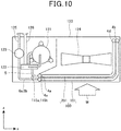
- Fig. 10 is an x-z plan view illustrating an internal structure of the outdoor unit 120 using the heat exchangers 101 and 201 of the present embodiment.
- Fig. 11 is an x-y plan view illustrating the internal structure of the outdoor unit 120 using the heat exchangers 101 and 201 of the present embodiment.
- the outdoor unit 120 includes a compressor 121, a switching valve 122, an outdoor expansion valve 123, a blower 124, and the heat exchanger 100.
- the outdoor unit 120 and an indoor unit are connected by a liquid pipe 125 and a gas pipe 126.
- a direction W of an air flow caused by the blower 124 is indicated by an arrow in Fig. 10 .
- the header pipe 4a of the heat exchanger 201 is connected to the switching valve 122 via the first refrigerant pipe 5.
- each of the heat exchangers 101 and 201 is formed in a substantially L shape as viewed from the top.
- each of the heat exchangers 101 and 201 functions as a condenser.
- a refrigerant flow at the time of a heating operation described later is indicated by arrows.
- a refrigerant flow at the time of the cooling operation is not illustrated.
- a gas refrigerant sent from the compressor 121 of the outdoor unit 120 flows into the header pipe 4a of the heat exchanger 201 from the first refrigerant pipe 5 via the switching valve 122.
- This gas refrigerant passes through the upper space 9a of the header pipe 4a in the heat exchanger 201, flows into refrigerant flow paths of the plurality of flat tubes 2, flows in the horizontal direction (+x direction, +z direction) and then flows out to the upper side of the header pipe 4b of the heat exchanger 201.
- the refrigerant that has flowed out to the header pipe 4b of the heat exchanger 201 moves down in the -y direction in the header pipe 4b, flows in the horizontal direction (-z direction, -x direction) via the refrigerant flow paths of the plurality of flat tubes 2 and then flows to the refrigerant outflow space 11 of the header pipe 4a of the heat exchanger 201.
- the refrigerant dissipates heat in the flat tube 2.
- the refrigerant in the refrigerant outflow space 11 passes through the communication holes 12a and 12b of the upper-side partition plate 7a and the lower-side partition plate 7b and then flows into the first refrigerant inflow space 10a and second refrigerant inflow space 10b of the heat exchanger 201.
- the refrigerant that has flowed to the first refrigerant inflow space 10a passes through the connection pipe 115a and then flows into the upper space 9a of the header pipe 4a of the heat exchanger 101.
- the refrigerant that has flowed to the second refrigerant inflow space 10b passes through the connection pipe 115b and then flows into the upper space 9a of the header pipe 4a of the heat exchanger 101.
- the refrigerant that has flowed into the upper space 9a flows into refrigerant flow paths of the plurality of flat tubes 2, flows in the horizontal direction (+x direction, +z direction) and then flows into an upper part in the header pipe 4b of the heat exchanger 101.
- This refrigerant moves down in the header pipe 4b in the -y direction and then flows in the horizontal direction (-z direction, -x direction) via the refrigerant flow paths of the plurality of flat tubes 2.
- the refrigerant dissipates heat through heat exchange with air sent by the blower 124 and condenses.
- the refrigerant condensed in the flat tube 2 flows into the refrigerant outflow space 11 of the header pipe 4a of the heat exchanger 101, passes through the communication holes 12a and 12b of the upper-side partition plate 7a and the lower-side partition plate 7b and then flows into the first refrigerant inflow space 10a and second refrigerant inflow space 10b of the heat exchanger 101.
- This refrigerant passes through the outdoor expansion valve 123 and the liquid pipe 125 via the second refrigerant pipes 6a and 6b and then flows to the indoor unit.
- the condensed refrigerant flowing to the indoor unit absorbs heat through heat exchange with air in an indoor heat exchanger (not illustrated) and evaporates.
- the evaporated refrigerant passes through the gas pipe 126 and then returns to the compressor 121 via the switching valve 122.
- the heat exchanger 101 functions as an evaporator.
- a gas refrigerant sent from the compressor 121 of the outdoor unit 120 passes through the gas pipe 126 via the switching valve 122 and then flows to the indoor unit.
- the gas refrigerant that has flowed to the indoor unit dissipates heat through heat exchange with air in the indoor heat exchanger provided in the indoor unit and condenses.
- the refrigerant condensed in the indoor heat exchanger passes through the liquid pipe 125 and the outdoor expansion valve 123 to become a gas-liquid two-phase refrigerant and then flows from the second refrigerant pipes 6a and 6b to the first refrigerant inflow space 10a and second refrigerant inflow space 10b of the heat exchanger 101.
- the refrigerant that has flowed into the first refrigerant inflow space 10a of the heat exchanger 101 passes through the communication hole 12a provided in the upper-side partition plate 7a and then flows to the refrigerant outflow space 11.
- the refrigerant that has flowed into the second refrigerant inflow space 10b of the heat exchanger 101 passes through the communication hole 12b provided in the lower-side partition plate 7b and then flows to the refrigerant outflow space 11.
- the refrigerant that has flowed into the refrigerant outflow space 11 of the heat exchanger 101 flows in the horizontal direction (+x direction, +z direction) via the refrigerant flow paths of the plurality of flat tubes 2 and then flows to a lower part in the header pipe 4b of the heat exchanger 101.
- This refrigerant moves up in the +y direction in the header pipe 4b, flows in the horizontal direction (-z direction, -x direction) via the refrigerant flow paths of the plurality of flat tubes 2 and then flows to the upper space 9a of the header pipe 4a of the heat exchanger 101. At this time, the refrigerant absorbs heat in the flat tube 2.
- the refrigerant that has flowed to the upper space 9a of the heat exchanger 101 passes through the connection pipes 115a and 115b and then flows into the header pipe 4a of the heat exchanger 201.
- the refrigerant in the upper space 9a of the heat exchanger 101 flows out to the outside of the heat exchanger 101 via the connection pipe 115a and then flows into the first refrigerant inflow space 10a of the heat exchanger 201 via the connection pipe 115a.
- the refrigerant in the upper space 9a of the heat exchanger 101 flows out to the outside of the heat exchanger 101 via the connection pipe 115b and then flows into the second refrigerant inflow space 10b of the heat exchanger 201 via the connection pipe 115b.
- connection pipe 115a functions as a first refrigerant pipe allowing the refrigerant to flow out to the outside of the heat exchanger 101.
- connection pipe 115a functions as a second refrigerant pipe through which the refrigerant flows into the heat exchanger 201 from the outside.
- connection pipe 115b functions as a first refrigerant pipe allowing the refrigerant to flow out to the outside of the heat exchanger 101. That is, two first refrigerant pipes (connection pipes 115a and 115b) are connected to the heat exchanger 101.
- connection pipe 115b functions as a second refrigerant pipe through which the refrigerant flows into the heat exchanger 201 from the outside. That is, two second refrigerant pipes (connection pipes 115a and 115b) are connected to the heat exchanger 201.
- the refrigerant that has flowed into the first refrigerant inflow space 10a of the heat exchanger 201 passes through the communication hole 12a provided in the upper-side partition plate 7a and then flows to the refrigerant outflow space 11.
- the refrigerant that has flowed into the second refrigerant inflow space 10b of the heat exchanger 201 passes through the communication hole 12b provided in the lower-side partition plate 7b and then flows to the refrigerant outflow space 11.
- the refrigerant that has flowed to the refrigerant outflow space 11 of the heat exchanger 201 flows in the horizontal direction (+x direction, +z direction) via the refrigerant flow paths of the plurality of flat tubes 2 and then flows to a lower part in the header pipe 4b of the heat exchanger 201.
- the refrigerant that has flowed to the header pipe 4b moves up in the +y direction in the header pipe 4b and then flows in the horizontal direction (-z direction, -x direction) via the refrigerant flow paths of the plurality of flat tubes 2.
- the refrigerant absorbs heat through heat exchange with air sent by the blower 124 and evaporates.
- the evaporated refrigerant flows into the upper space 9a of the header pipe 4a of the heat exchanger 201 and then returns from the first refrigerant pipe 5 to the compressor 121 via the switching valve 122.
- the heat exchanger 101 includes the plurality of flat tubes 2 each forming the refrigerant flow path, and the pair of header pipes 4a and 4b connected to respective end parts of each flat tube 2; in the case where the heat exchanger 101 functions as an evaporator, the connection pipes 115a and 115b as the two first refrigerant pipes from which the refrigerant flows out and the plurality of second refrigerant pipes 6a and 6b into which the refrigerant flows are provided in the header pipe 4a; a refrigerant dividing section 14 is provided in the header pipe 4a to which the plurality of second refrigerant pipes 6a and 6b are connected, wherein the refrigerant dividing section 14 is formed by the first refrigerant inflow space 10a and the second refrigerant inflow space 10b into which the refrigerant flows from the plurality of second refrigerant pipes 6a and 6b, the refrigerant outflow space 11 provided between the first refrigerant inflow space 10a
- the refrigerant passes through the communication holes 12a and 12b of the partition plates 7 from the first refrigerant inflow space 10a above the refrigerant outflow space 11 and the second refrigerant inflow space 10b below the refrigerant outflow space 11 and then flows into the refrigerant outflow space 11 from above and below.
- the heat exchanger 201 includes the plurality of flat tubes 2 each forming the refrigerant flow path, and the pair of header pipes 4a and 4b connected to respective end parts of each flat tube 2; in the case where the heat exchanger 201 functions as an evaporator, the first refrigerant pipe 5 from which the refrigerant flows out and the connection pipes 115a and 115b as a plurality of the second refrigerant pipes into which the refrigerant flows are provided in the header pipe 4a; a refrigerant dividing section 14 is provided in the header pipe 4a to which the plurality of connection pipes 115a and 115b are connected, wherein the refrigerant dividing section 14 is formed by the first refrigerant inflow space 10a and the second refrigerant inflow space 10b into which the refrigerant flows from the plurality of connection pipes 115a and 115b, the refrigerant outflow space 11 provided between the first refrigerant inflow space 10a and the second refrigerant inflow space 10b
- the refrigerant passes through the communication holes 12a and 12b of the partition plates 7 from the first refrigerant inflow space 10a above the refrigerant outflow space 11 and the second refrigerant inflow space 10b below the refrigerant outflow space 11 and then flows into the refrigerant outflow space 11 from above and below.
- the heat exchanger 100 formed by arranging the heat exchanger 101 and the heat exchanger 201 in the direction of the air flow (z direction) can be used for large-scale air conditioning which requires a large capacity.
- the heat exchanger 100 even in the configuration in which the heat exchanger 101 and the heat exchanger 201 are connected by the connection pipes 115a and 115b, separation between a liquid refrigerant and a gas refrigerant due to a difference in density caused by an increase in gas ratio is prevented. This can prevent the liquid refrigerant from leaning to the flat tubes 2 on the lower side and can prevent the gas refrigerant from leaning to the flat tubes 2 on the upper side, so that the refrigerant can uniformly flow to the plurality of flat tubes 2.
- the present disclosure is a heat exchanger including a plurality of flat tubes each forming a refrigerant flow path, and a pair of header pipes connected to respective end parts of each flat tube; in the case where the heat exchanger functions as an evaporator, a first refrigerant pipe from which a refrigerant flows out and a plurality of second refrigerant pipes into which the refrigerant flows are provided in a header pipe of the header pipes; a refrigerant dividing section is provided in the header pipe to which the plurality of second refrigerant pipes are connected, wherein the refrigerant dividing section is formed by a plurality of refrigerant inflow spaces into which the refrigerant flows from the plurality of second refrigerant pipes, a refrigerant outflow space provided between the plurality of refrigerant inflow spaces, and a plurality of partition plates separating the plurality of refrigerant inflow spaces and the refrigerant outflow space, and the refrigerant outflow space allows the refrig
Abstract
Description
- The present disclosure relates to a heat exchanger including a pair of header pipes and a plurality of flat tubes forming a plurality of refrigerant flow paths to exchange heat between air flowing between the flat tubes and a refrigerant flowing through the refrigerant flow paths of the flat tubes.
-
Japanese Patent Laid-Open No. 2016-53473 - The present disclosure provides a heat exchanger that can allow a refrigerant to uniformly flow to a plurality of flat tubes.
- In a heat exchanger in the present disclosure which includes a plurality of flat tubes each forming a refrigerant flow path, and a pair of header pipes connected to respective end parts of each flat tube, in the case where the heat exchanger functions as an evaporator, at least one or more first refrigerant pipes from which a refrigerant flows out and a plurality of second refrigerant pipes into which the refrigerant flows are provided in a header pipe of the header pipes; a refrigerant dividing section is provided in the header pipe to which the plurality of second refrigerant pipes are connected, wherein the refrigerant dividing section is formed by a plurality of refrigerant inflow spaces into which the refrigerant flows from the plurality of second refrigerant pipes, a refrigerant outflow space provided between the plurality of refrigerant inflow spaces, and a plurality of partition plates separating the plurality of refrigerant inflow spaces and the refrigerant outflow space, and the refrigerant outflow space allows the refrigerant to flow out to the flat tube; and the partition plates are provided with communication holes, respectively, allowing the refrigerant outflow space to communicate with a refrigerant inflow space of the refrigerant inflow spaces above the refrigerant outflow space and a refrigerant inflow space of the refrigerant inflow spaces below the refrigerant outflow space.
- In the heat exchanger in the present disclosure, the refrigerant passes through the communication holes of the partition plates from the refrigerant inflow space above the refrigerant outflow space and the refrigerant inflow space below the refrigerant outflow space and then flows into the refrigerant outflow space from above and below. This prevents the refrigerant flowing from the second refrigerant pipe into the refrigerant outflow space of the header pipe from flowing straight toward the flat tube, so that the refrigerant flow can spread over a wide range in the refrigerant outflow space. Therefore, the refrigerant can uniformly flow to the plurality of flat tubes.
-
-
Fig. 1 is a perspective view of a heat exchanger inEmbodiment 1; -
Fig. 2 is a cross-sectional view of an x-y plane of the heat exchanger in Embodiment 1 (a cross-sectional view taken along A-A ofFig. 1 ); -
Fig. 3 is an enlarged view of the x-y plane of the heat exchanger in Embodiment 1 (an enlarged view of B ofFig. 2 ); -
Fig. 4 is an enlarged view of the x-y plane of the heat exchanger in Embodiment 1 (an enlarged view of C ofFig. 2 ); -
Fig. 5 is an x-z plan view illustrating an internal structure of an outdoor unit using the heat exchanger ofEmbodiment 1; -
Fig. 6 is an x-y plan view illustrating the internal structure of the outdoor unit using the heat exchanger ofEmbodiment 1; -
Fig. 7 is a perspective view of a heat exchanger inEmbodiment 2; -
Fig. 8 is a cross-sectional view of an x-y plane of the heat exchanger in Embodiment 2 (a cross-sectional view taken along D-D ofFig. 7 ); -
Fig. 9 is a cross-sectional view of the x-y plane of the heat exchanger in Embodiment 2 (a cross-sectional view taken along E-E ofFig. 7 ); -
Fig. 10 is an x-z plan view illustrating an internal structure of an outdoor unit using the heat exchanger ofEmbodiment 2; and -
Fig. 11 is an x-y plan view illustrating the internal structure of the outdoor unit using the heat exchanger ofEmbodiment 2. - A heat exchanger is known which includes, as in the above conventional art, a pair of header pipes facing each other on the left and right sides in the horizontal direction, a plurality of flat tubes forming a plurality of refrigerant flow paths, and a heat transfer fin provided between the flat tubes, to exchange heat between air flowing between the plurality of flat tubes and a refrigerant flowing through the refrigerant flow paths of the flat tubes. Some of this type of heat exchangers is, in order to uniformize a ratio between an amount of the refrigerant and a gas-liquid refrigerant which flow through the plurality of flat tubes in the header pipes, provided with a partition plate separating the inside of the header pipe into a plurality of sections, and a connection tube allowing, in two separate sections, a lower part of the section on the upper side and an upper part of the section on the lower side to communicate with each other.
- In the case where the above conventional heat exchanger functions as an evaporator, the refrigerant that has flowed from a refrigerant circuit into the header pipe passes through the flat tubes and then flows to the section on the lower side in the header pipe. The refrigerant that has flowed to the section on the lower side in the header pipe flows into the section on the upper side in the header pipe via the connection tube. This prevents gas-liquid separation of the refrigerant due to the influence of gravity when the refrigerant rises in the header pipe and then turns, so that the ratio between the amount of the refrigerant and the gas-liquid refrigerant which flow through the plurality of flat tubes connected to the section on the upper side of the header pipe can be made uniform.
- However, in the conventional configuration, the refrigerant that has flowed from the connection tube into the header pipe flows straight toward the flat tubes; accordingly, the refrigerant is likely to flow while leaning to the flat tubes inserted in the vicinity of the connection tube. Thus, the refrigerant flowing from the header pipe to the plurality of flat pipes is likely to become nonuniform.
- The present disclosure provides a heat exchanger that can allow a refrigerant to uniformly flow into a plurality of flat tubes.
- Hereinafter, embodiments will be described in detail with reference to the drawings. However, unnecessarily detailed description may be omitted. For example, detailed description of already well-known matters or redundant description of substantially the same configurations may be omitted.
- The attached drawings and the following description are provided to allow those skilled in the art to sufficiently understand the present disclosure and are not intended to limit the subject matter described in the claims.
- Hereinafter, configurations of
Embodiment 1 will be described with reference toFigs. 1 to 4 . -
Fig. 1 is a perspective view of aheat exchanger 1 ofEmbodiment 1 of the present invention. In the figures, the x direction denotes the arrangement direction offins 3; the y direction, the arrangement direction offlat tubes 2; the z direction, the flow direction of air passing through theflat tubes 2.Fig. 2 is a cross-sectional view taken along A-A ofFig. 1 (a cross-sectional view of an x-y plane ofEmbodiment 1 of the present disclosure).Fig. 3 is an enlarged view of B ofFig. 2 (an enlarged view of the x-y plane of the heat exchanger ofEmbodiment 1 of the present disclosure).Fig. 4 is an enlarged view of C ofFig. 2 (an enlarged view of the x-y plane of the heat exchanger ofEmbodiment 1 of the present disclosure). - In
Figs. 1 to 4 , theheat exchanger 1 includes a plurality of theflat tubes 2, a plurality of thefins 3, a pair ofheader pipes first refrigerant pipe 5, a plurality ofsecond refrigerant pipes partition plate 7, and apartition wall 8. Theheat exchanger 1 has a plate shape extending in the up-down direction. The plate thickness direction of theheat exchanger 1 is the flow direction of the air passing through the flat tubes 2 (z direction). - Each of the
header pipes - One
header pipe 4a includes a tubular part 4a1 having a cylindrical shape extending in the up-down direction, an upper wall part 4a2 closing an upper end of the tubular part 4a1, and a lower wall part 4a3 closing a lower end of the tubular part 4a1. - The
other header pipe 4b includes a tubular part 4b1 having a cylindrical shape extending in the up-down direction, an upper wall part 4b2 closing an upper end of the tubular part 4b1, and a lower wall part 4b3 closing a lower end of the tubular part 4b1. - An
axis 4c of each of theheader pipes header pipes - Each of the
header pipes - The
flat tube 2 extends in the horizontal direction and connects the oneheader pipe 4a and theother header pipe 4b. That is, theflat tube 2 is disposed in the direction orthogonal to theheader pipes - The
flat tubes 2 are arranged at substantially equal intervals in the height direction of theheader pipes flat tubes 2 are disposed in parallel to each other. Here, the height direction of theheader pipes header pipes - The
flat tube 2 connects the tubular part 4a1 of the oneheader pipe 4a and the tubular part 4b1 of theother header pipe 4b. - Specifically, in the
flat tube 2, oneend 2a (end part) in the axis direction of theflat tube 2 is connected to the tubular part 4a1, and theother end 2b in the axis direction of theflat tube 2 is connected to the tubular part 4b1. - The one
end 2a of theflat tube 2 is inserted into an outer periphery of the tubular part 4a1 of theheader pipe 4a from the outside, and this inserted portion is coupled to the tubular part 4a1 by welding or the like. The oneend 2a of theflat tube 2 projects into the inside of the tubular part 4a1. - The inside of the
flat tube 2 is a refrigerant flow path through which a refrigerant flows. The oneheader pipe 4a and theother header pipe 4b communicate with each other via theflat tube 2. - The
fin 3 is a plate disposed in the direction orthogonal to theflat tube 2, between the oneheader pipe 4a and theother header pipe 4b. The plurality offins 3 are disposed at intervals in the axis direction of theflat tube 2. Specifically, theflat tube 2 is inserted into a hole provided in each of thefins 3 and is in contact with theflat tube 2. - The
heat exchanger 1 exchanges heat between air flowing between the plurality offins 3 and a refrigerant flowing through the plurality offlat tubes 2. - As the refrigerant, for example, R410A, R32, or a mixed refrigerant containing R32 is used.
- The
partition wall 8 having a disc shape is provided in the oneheader pipe 4a. Thepartition wall 8 separates a space in the oneheader pipe 4a into anupper space 9a on the upper side of thepartition wall 8 and alower space 9b on the lower side of thepartition wall 8. Thepartition wall 8 is a disc-shaped plate provided at a middle part in the up-down direction of the tubular part 4a1. - An upper end of the
upper space 9a is defined by the upper wall part 4a2. A lower end of thelower space 9b is defined by the lower wall part 4a3. - The
upper space 9a communicates with an upper part of theother header pipe 4b via theflat tube 2 connected to a portion defining theupper space 9a in the tubular part 4a1 of the oneheader pipe 4a. - In the one
header pipe 4a, thelower space 9b is provided with thepartition plate 7. - The
partition plate 7 is formed by an upper-side partition plate 7a located at an upper part of thelower space 9b and a lower-side partition plate 7b located at a lower part of thelower space 9b. Each of the upper-side partition plate 7a and the lower-side partition plate 7b is a disc-shaped plate separating the inside of the tubular part 4a1 in the up-down direction. - The
lower space 9b of the oneheader pipe 4a is provided with a firstrefrigerant inflow space 10a defined by thepartition wall 8 and the upper-side partition plate 7a in the up-down direction (the axis direction of theheader pipe 4a), and a secondrefrigerant inflow space 10b defined by the lower-side partition plate 7b and the lower wall part 4a3 in the up-down direction. - Furthermore, the
lower space 9b of the oneheader pipe 4a is provided with arefrigerant outflow space 11 defined by the upper-side partition plate 7a and the lower-side partition plate 7b in the up-down direction. - The
refrigerant outflow space 11 is provided between the firstrefrigerant inflow space 10a and the secondrefrigerant inflow space 10b in the up-down direction. Furthermore, the firstrefrigerant inflow space 10a is located above therefrigerant outflow space 11, and the secondrefrigerant inflow space 10b is located below therefrigerant outflow space 11. - The
refrigerant outflow space 11 is longer in the up-down direction than the firstrefrigerant inflow space 10a and the secondrefrigerant inflow space 10b. - Each of the first
refrigerant pipe 5 and the plurality of secondrefrigerant pipes header pipe 4a. Each of the firstrefrigerant pipe 5 and the plurality of secondrefrigerant pipes - The first
refrigerant pipe 5 is connected to an upper part of the oneheader pipe 4a and communicates with theupper space 9a. - The second
refrigerant pipe 6a on the upper side is connected to a middle part in the up-down direction of the oneheader pipe 4a and communicates with the firstrefrigerant inflow space 10a. - Specifically, an end part 6a1 of the second
refrigerant pipe 6a is connected to an outer periphery of a portion defining the firstrefrigerant inflow space 10a in the tubular part 4a1. That is, the secondrefrigerant pipe 6a is connected to a portion below thepartition wall 8 and above the upper-side partition plate 7a in the tubular part 4a1. - The end part 6a1 of the second
refrigerant pipe 6a is disposed so as to be located on the opposite side in the tubular part 4a1 with respect to the oneend 2a of theflat tube 2 inserted into the tubular part 4a1 from the outside and face the oneend 2a of theflat tube 2. That is, the end part 6a1 of the secondrefrigerant pipe 6a is provided on the side where theflat tube 2 is not inserted in the tubular part 4a1. Here, the side where theflat tube 2 is not inserted in the tubular part 4a1 means the side far from a portion where theflat tube 2 is inserted in the tubular part 4a1. - The end part 6a1 of the second
refrigerant pipe 6a extends in the horizontal direction and is parallel to theflat tube 2. - The second
refrigerant pipe 6b on the lower side is connected to a lower part of the oneheader pipe 4a and communicates with the secondrefrigerant inflow space 10b. - Specifically, an end part 6b1 of the second
refrigerant pipe 6b is connected to an outer periphery of a portion defining the secondrefrigerant inflow space 10b in the tubular part 4a1. That is, the secondrefrigerant pipe 6b is connected to a portion below the lower-side partition plate 7b and above the lower wall part 4a3 in the tubular part 4a1. - The end part 6b1 of the second
refrigerant pipe 6b is disposed so as to be located on the opposite side in the tubular part 4a1 with respect to the oneend 2a of theflat tube 2 inserted into the tubular part 4a1 from the outside and face the oneend 2a of theflat tube 2. That is, the end part 6b1 of the secondrefrigerant pipe 6b is provided on the side where theflat tube 2 is not inserted in the tubular part 4a1. - The end part 6b1 of the second
refrigerant pipe 6b extends in the horizontal direction and is parallel to theflat tube 2. - In the
lower space 9b, theflat tube 2 communicates with therefrigerant outflow space 11. The plurality offlat tubes 2 are connected to a portion defining therefrigerant outflow space 11 in the outer periphery of the tubular part 4a1. That is, the plurality offlat tubes 2 are arranged in the up-down direction at a portion between the upper-side partition plate 7a and the lower-side partition plate 7b in the tubular part 4a1. - Each of the second
refrigerant pipes side partition plate 7a, and the lower-side partition plate 7b is disposed at a position different from each of theflat tubes 2 in the height direction of theheader pipe 4a. - The upper-
side partition plate 7a is provided with acommunication hole 12a allowing therefrigerant outflow space 11 to communicate with the firstrefrigerant inflow space 10a above therefrigerant outflow space 11. - The
communication hole 12a is a round hole penetrating the upper-side partition plate 7a in the height direction of theheader pipe 4a (the axis direction of theheader pipe 4a). The axis direction of thecommunication hole 12a is the height direction of theheader pipe 4a, and the axis direction of thecommunication hole 12a is orthogonal to the axis direction of the flat tube 2 (horizontal direction). - The
communication hole 12a is, on the upper-side partition plate 7a, disposed closer to the side where theflat tube 2 is not inserted. That is, thecommunication hole 12a is, in the horizontal direction, disposed closer to the end part 6a1 side of the secondrefrigerant pipe 6a relative to the oneend 2a side of theflat tube 2. - A surface on the side of the
refrigerant outflow space 11 in the upper-side partition plate 7a, that is, a lower surface of the upper-side partition plate 7a is provided with aninclined surface 13a descending from the side where theflat tube 2 is not inserted in theheader pipe 4a toward the side where theflat tube 2 is inserted in theheader pipe 4a. - The
communication hole 12a is present ahead of theinclined surface 13a ascending from the side where theflat tube 2 is inserted in theheader pipe 4a toward the side where theflat tube 2 is not inserted in theheader pipe 4a. - The lower-
side partition plate 7b is provided with acommunication hole 12b allowing therefrigerant outflow space 11 to communicate with the secondrefrigerant inflow space 10b below therefrigerant outflow space 11. - The
communication hole 12b is a round hole penetrating the lower-side partition plate 7b in the height direction of theheader pipe 4a (the axis direction of theheader pipe 4a). The axis direction of thecommunication hole 12b is the height direction of theheader pipe 4a, and the axis direction of thecommunication hole 12b is orthogonal to the axis direction of the flat tube 2 (horizontal direction). - The
communication hole 12b is, on the lower-side partition plate 7b, disposed closer to the side where theflat tube 2 is inserted. That is, thecommunication hole 12b is, in the horizontal direction, disposed closer to the oneend 2a side of theflat tube 2 relative to the end part 6a1 side of the secondrefrigerant pipe 6a. - A surface on the side of the
refrigerant outflow space 11 in the lower-side partition plate 7b, that is, an upper surface of the lower-side partition plate 7b is provided with aninclined surface 13b descending from the side where theflat tube 2 is not inserted in theheader pipe 4a toward the side where theflat tube 2 is inserted in theheader pipe 4a. - The
communication hole 12b is present ahead of theinclined surface 13b descending from the side where theflat tube 2 is not inserted in theheader pipe 4a toward the side where theflat tube 2 is inserted in theheader pipe 4a. - With reference to
Figs. 2 and4 , when thecommunication hole 12b is viewed in the axis direction of theheader pipe 4a (the y direction in the figures), thecommunication hole 12b is spaced apart from the oneend 2a of theflat tube 2 toward the side where theflat tube 2 is not inserted. That is, thecommunication hole 12b is provided at a position not overlapping with the oneend 2a of theflat tube 2, as viewed in the axis direction of theheader pipe 4a. - Furthermore, with reference to
Fig. 2 , thecommunication hole 12a of the upper-side partition plate 7a is disposed nearer the side where theflat tube 2 is not inserted in theheader pipe 4a than thecommunication hole 12b of the lower-side partition plate 7b. - The first
refrigerant inflow space 10a, the secondrefrigerant inflow space 10b, therefrigerant outflow space 11, the upper-side partition plate 7a, and the lower-side partition plate 7b form arefrigerant dividing section 14 that divides the refrigerant flowing into theheader pipe 4a into the plurality offlat tubes 2. - Operations and functions of the
heat exchanger 1 configured as above will be described below. - As an example, a case where the
heat exchanger 1 of the present embodiment is used in anoutdoor unit 20 of an air conditioning apparatus will be described with reference toFigs. 5 and6 . -
Fig. 5 is an x-z plan view illustrating an internal structure of theoutdoor unit 20 using theheat exchanger 1 of the present embodiment, andFig. 6 is an x-y plan view illustrating the internal structure of theoutdoor unit 20 using theheat exchanger 1 of the present embodiment. - As illustrated in
Figs. 5 and6 , theoutdoor unit 20 includes acompressor 21, a switchingvalve 22, anoutdoor expansion valve 23, ablower 24, and theheat exchanger 1. Theoutdoor unit 20 and an indoor unit (not illustrated) are connected by aliquid pipe 25 and agas pipe 26. A direction W of an air flow caused by theblower 24 is indicated by an arrow inFig. 5 . - The
header pipe 4a of theheat exchanger 1 is connected to the switchingvalve 22 via the firstrefrigerant pipe 5. Furthermore, theheader pipe 4a is connected to theoutdoor expansion valve 23 via the plurality of secondrefrigerant pipes Figs. 5 and6 , theheat exchanger 1 is formed in a substantially L shape as viewed from the top. - In the case where a cooling operation is performed, the
heat exchanger 1 functions as a condenser. InFig. 2 , a refrigerant flow at the time of a heating operation described later is indicated by arrows. A refrigerant flow at the time of the cooling operation is not illustrated. - In the cooling operation, a gas refrigerant sent from the
compressor 21 of theoutdoor unit 20 flows from the firstrefrigerant pipe 5 into theheader pipe 4a via the switchingvalve 22. This gas refrigerant passes through the inside of theupper space 9a of theheader pipe 4a, flows into a plurality of the refrigerant flow paths in the plurality offlat tubes 2, flows in the horizontal direction (+x direction, +z direction) and then flows to the upper part in theheader pipe 4b. - The refrigerant in the
header pipe 4b moves down in the -y direction and then flows in the horizontal direction (-z direction, -x direction) via the plurality of refrigerant flow paths in the plurality offlat tubes 2. In theflat tube 2, the refrigerant dissipates heat through heat exchange with air sent by theblower 24 and condenses. - The condensed refrigerant flows out to the
refrigerant outflow space 11 defined by the upper-side partition plate 7a and the lower-side partition plate 7b and then flows into the firstrefrigerant inflow space 10a and the secondrefrigerant inflow space 10b while passing through therespective communication holes side partition plate 7a and the lower-side partition plate 7b. - The refrigerant that has flowed into the first
refrigerant inflow space 10a and the secondrefrigerant inflow space 10b passes through theoutdoor expansion valve 23 and theliquid pipe 25 via the secondrefrigerant pipes - The condensed refrigerant flowing to the indoor unit absorbs heat through heat exchange with air in an indoor heat exchanger (not illustrated) and evaporates. The evaporated refrigerant passes through the
gas pipe 26 and then returns to thecompressor 21 via the switchingvalve 22. - In the case where the heating operation is performed, the
heat exchanger 1 functions as an evaporator. - In the heating operation, a gas refrigerant sent from the
compressor 21 of theoutdoor unit 20 passes through thegas pipe 26 via the switchingvalve 22 and then flows out to the indoor unit (not illustrated). - The gas refrigerant that has flowed to the indoor unit dissipates heat through heat exchange with air in the indoor heat exchanger provided in the indoor unit and condenses.
- The condensed refrigerant passes through the
liquid pipe 25 and theoutdoor expansion valve 23 to become a gas-liquid two-phase refrigerant and then flows to the firstrefrigerant inflow space 10a and the secondrefrigerant inflow space 10b from the respective secondrefrigerant pipes - The refrigerant that has flowed to the first
refrigerant inflow space 10a passes through thecommunication hole 12a of the upper-side partition plate 7a and then flows into therefrigerant outflow space 11 from the upper side. The refrigerant passing through thecommunication hole 12a flows downward in therefrigerant outflow space 11 along the axis direction of thecommunication hole 12a. That is, the refrigerant flowing from thecommunication hole 12a to therefrigerant outflow space 11 flows in the direction orthogonal to the axis direction of theflat tube 2. - Specifically, the
communication hole 12a is provided on the side where theflat tube 2 is not inserted in the tubular part 4a1; accordingly, the refrigerant flowing downward from thecommunication hole 12a, in therefrigerant outflow space 11, flows downward at the position on the side where theflat tube 2 is not inserted. - The refrigerant that has flowed to the second
refrigerant inflow space 10b passes through thecommunication hole 12b of the lower-side partition plate 7b and then flows into therefrigerant outflow space 11 from the lower side. The refrigerant passing through thecommunication hole 12b flows upward in therefrigerant outflow space 11 along the axis direction of thecommunication hole 12b. That is, the refrigerant flowing from thecommunication hole 12b to therefrigerant outflow space 11 flows in the direction orthogonal to the axis direction of theflat tube 2. - Specifically, the
communication hole 12b is provided on the side where theflat tube 2 is inserted in the tubular part 4a1; accordingly, the refrigerant flowing upward from thecommunication hole 12b, in therefrigerant outflow space 11, flows upward at the position on the side where theflat tube 2 is inserted. - The refrigerant flowing while moving down from the
communication hole 12a to therefrigerant outflow space 11 is accelerated by gravity and accordingly is likely to flow more strongly than the refrigerant flowing while moving up from thecommunication hole 12b to therefrigerant outflow space 11. - The
communication hole 12b is offset to the side where theflat tube 2 is not inserted in the tubular part 4a1, relative to the oneend 2a of theflat tube 2, and does not overlap with the oneend 2a, as viewed in the axis direction of theheader pipe 4a. Thus, the refrigerant flowing from thecommunication hole 12b into therefrigerant outflow space 11 flows upward in therefrigerant outflow space 11 so as to avoid the oneend 2a. - A part of the refrigerant flowing from the
communication hole 12b into therefrigerant outflow space 11 moves up and then reaches the vicinity of the lower surface of the upper-side partition plate 7a. This refrigerant, along theinclined surface 13a of the lower surface of the upper-side partition plate 7a, flows from the side where theflat tube 2 is inserted to the side where theflat tube 2 is not inserted, reaches thecommunication hole 12a side and then joins the flow flowing from thecommunication hole 12a into therefrigerant outflow space 11. - A part of the refrigerant flowing from the
communication hole 12a into therefrigerant outflow space 11 reaches the vicinity of the upper surface of the lower-side partition plate 7b. This refrigerant, along theinclined surface 13b of the upper surface of the lower-side partition plate 7b, flows from the side where theflat tube 2 is not inserted to the side where theflat tube 2 is inserted, reaches thecommunication hole 12b side and then joins the flow flowing from thecommunication hole 12b into therefrigerant outflow space 11. - The refrigerant that has flowed into the
refrigerant outflow space 11 flows from the oneend 2a into theflat tube 2, flows in the horizontal direction (+x direction, +z direction) via the refrigerant flow paths in the plurality offlat tubes 2 and then flows to a lower part in theother header pipe 4b. - The refrigerant that has flowed into the
header pipe 4b moves up in the +y direction in theheader pipe 4b and then flows in the horizontal direction (-z direction, -x direction) via the refrigerant flow paths in the plurality offlat tubes 2 connected to the upper part of theheader pipe 4b. In theflat tube 2, the refrigerant absorbs heat through heat exchange with air sent by theblower 24 and evaporates. - The refrigerant that has evaporated in the
flat tube 2 flows into theupper space 9a of theheader pipe 4a and then returns from the firstrefrigerant pipe 5 to thecompressor 21 via the switchingvalve 22. - As above, in the present embodiment, the heat exchanger 1 includes the plurality of flat tubes 2 each forming the refrigerant flow path and the pair of header pipes 4a and 4b connected to respective end parts of each flat tube 2; in the case where the heat exchanger 1 functions as an evaporator, at least one or more first refrigerant pipes 5 from which a refrigerant flows out and the plurality of second refrigerant pipes 6a and 6b into which the refrigerant flows are provided in the header pipe 4a; the refrigerant dividing section 14 is provided in the header pipe 4a to which the plurality of second refrigerant pipes 6a and 6b are connected, wherein the refrigerant dividing section 14 is formed by the first refrigerant inflow space 10a and the second refrigerant inflow space 10b into which the refrigerant flows from the plurality of second refrigerant pipes 6a and 6b, the refrigerant outflow space 11 provided between the first refrigerant inflow space 10a and the second refrigerant inflow space 10b, and the partition plates 7 separating the first refrigerant inflow space 10a and the second refrigerant inflow space 10b, and the refrigerant outflow space 11, and the refrigerant outflow space 11 allows the refrigerant to flow out to the flat tube 2; and the partition plates 7 are provided with the communication holes 12a and 12b allowing the refrigerant outflow space 11 to communicate with the first refrigerant inflow space 10a above the refrigerant outflow space 11 and the second refrigerant inflow space 10b below the refrigerant outflow space 11.
- Accordingly, the refrigerant passes through the
communication holes partition plates 7 from the firstrefrigerant inflow space 10a above therefrigerant outflow space 11 and the secondrefrigerant inflow space 10b below therefrigerant outflow space 11 and then flows into therefrigerant outflow space 11 from above and below. This prevents the refrigerant flowing from the secondrefrigerant pipes refrigerant outflow space 11 of theheader pipe 4a from flowing straight toward theflat tube 2, so that the refrigerant flow can spread over a wide range in therefrigerant outflow space 11. Therefore, the refrigerant can uniformly flow to the plurality offlat tubes 2. - Furthermore, as in the present embodiment, the
flat tube 2 may be connected to theheader pipe 4a such that the oneend 2a of theflat tube 2 is inserted into theheader pipe 4a, and thecommunication hole 12a provided in the upper-side partition plate 7a located above therefrigerant outflow space 11 may be provided nearer the side where theflat tube 2 is not inserted in theheader pipe 4a than thecommunication hole 12b provided in the lower-side partition plate 7b located below therefrigerant outflow space 11. - Accordingly, the refrigerant flowing from the
communication hole 12a of the upper-side partition plate 7a to therefrigerant outflow space 11, in theheader pipe 4a, flows downward on the side where theflat tube 2 is not inserted and flows at a position far from theflat tube 2. Furthermore, the refrigerant flowing from thecommunication hole 12b of the lower-side partition plate 7b to therefrigerant outflow space 11, in theheader pipe 4a, flows upward on the side where theflat tube 2 is inserted, relative to thecommunication hole 12a, and flows at a position near theflat tube 2. Therefore, nonuniformity of the refrigerant flow in therefrigerant outflow space 11 can be reduced, and the refrigerant can uniformly flow to the plurality offlat tubes 2. For example, when the air conditioning apparatus is operated in a partial load operation and thereby the amount of the refrigerant circulation becomes small and the refrigerant flow rate becomes slow, the refrigerant which is likely to move down due to the influence of gravity moves down at the position far from theflat tube 2, and the refrigerant which is less likely to move up due to the influence of gravity moves up at the position near theflat tube 2. As a result, the flow of the refrigerant flowing to theflat tube 2 is prevented from leaning to an upper part of therefrigerant outflow space 11, so that the refrigerant can uniformly flow to the plurality offlat tubes 2. - Furthermore, as in the present embodiment, the
communication hole 12b provided in the lower-side partition plate 7b located below therefrigerant outflow space 11 may be provided at the position not overlapping with theflat tube 2 in theheader pipe 4a, when viewed from the axis direction of theheader pipe 4a. - This prevents the refrigerant flowing from the
communication hole 12b of the lower-side partition plate 7b into therefrigerant outflow space 11 from colliding with theflat tube 2 in theheader pipe 4a. Therefore, the refrigerant flowing from thecommunication hole 12b into therefrigerant outflow space 11 can effectively move up, and the refrigerant can uniformly flow to the plurality offlat tubes 2. For example, even when the air conditioning apparatus is operated in a minimum load operation and thereby the amount of the refrigerant circulation becomes smallest and the refrigerant flow rate becomes slow, the refrigerant moving up from below therefrigerant outflow space 11 is prevented from colliding with theflat tube 2 inserted into theheader pipe 4a. Therefore, the refrigerant can uniformly flow to the plurality offlat tubes 2. - Furthermore, as in the present embodiment, the surfaces on the sides of the
refrigerant outflow space 11 in the upper-side partition plate 7a and the lower-side partition plate 7b may be provided with theinclined surfaces flat tube 2 is not inserted in theheader pipe 4a toward the side where theflat tube 2 is inserted in theheader pipe 4a. - Accordingly, the refrigerant that has flowed from the
communication hole 12b of the lower-side partition plate 7b into therefrigerant outflow space 11 and then has moved up to the position of the upper-side partition plate 7a, along theinclined surface 13a, flows from the side where theflat tube 2 is inserted to the side where theflat tube 2 is not inserted, reaches thecommunication hole 12a side and then joins the flow flowing from thecommunication hole 12a into therefrigerant outflow space 11. Furthermore, the refrigerant that has flowed from thecommunication hole 12a of the upper-side partition plate 7a into therefrigerant outflow space 11 and then has moved down to the position of the lower-side partition plate 7b, along theinclined surface 13b, flows from the side where theflat tube 2 is not inserted to the side where theflat tube 2 is inserted, reaches thecommunication hole 12b side and then joins the flow flowing from thecommunication hole 12b into therefrigerant outflow space 11. Therefore, the refrigerant flow can spread over a wide range in therefrigerant outflow space 11, and the refrigerant can uniformly flow to the plurality offlat tubes 2. For example, even when the air conditioning apparatus is operated in an overload operation and thereby the amount of the refrigerant circulation becomes large and the refrigerant flow rate becomes fast, the refrigerant blowing up from below therefrigerant outflow space 11 is likely to reach above therefrigerant outflow space 11, and the refrigerant that has reached above therefrigerant outflow space 11 flows to thecommunication hole 12a along theinclined surface 13a of the upper-side partition plate 7a, flows to below therefrigerant outflow space 11 due to the refrigerant flowing from above therefrigerant outflow space 11 and then flows to theflat tube 2 side along theinclined surface 13b of the lower-side partition plate 7b, so that the refrigerant is prevented from flowing while leaning to theflat tube 2 of the upper part of therefrigerant outflow space 11. Therefore, the refrigerant can uniformly flow to the plurality offlat tubes 2. - Furthermore, as in the present embodiment, the axis direction of the
communication holes flat tube 2. - Accordingly, the flow flowing from the
communication holes refrigerant outflow space 11 is orthogonal to the axis direction of theflat tube 2, so that the refrigerant flowing from thecommunication holes refrigerant outflow space 11 and proceeding straight in the axis direction of thecommunication holes flat tube 2. Therefore, the refrigerant can uniformly flow to the plurality offlat tubes 2. It is sufficient that the axis direction of thecommunication holes flat tube 2. - Hereinafter,
Embodiment 2 will be described with reference toFigs. 7 to 11 . In thisEmbodiment 2, parts configured in the same manner as those inEmbodiment 1 above are denoted by the same reference signs, and description thereof will be omitted. -
Fig. 7 is a perspective view of aheat exchanger 100 ofEmbodiment 2 of the present invention.Fig. 8 is a cross-sectional view taken along D-D ofFig. 7 (a cross-sectional view of an x-y plane of aheat exchanger 101 disposed upstream of an air flow inEmbodiment 2 of the present disclosure).Fig. 9 is a cross-sectional view taken along E-E ofFig. 7 (a cross-sectional view of an x-y plane of aheat exchanger 201 disposed downstream of the air flow inEmbodiment 2 of the present disclosure). - The
heat exchanger 100 is configured such that a plurality of theheat exchangers heat exchangers heat exchanger 101 is disposed upstream of theheat exchanger 201 in the air flow passing through theheat exchanger 100 for heat exchange. - The
heat exchanger 101 includes a plurality offlat tubes 2, a plurality offins 3, a pair ofheader pipes refrigerant pipes side partition plate 7a and a lower-side partition plate 7b, and apartition wall 8. - The
partition wall 8 separates the inside of theheader pipe 4a of theheat exchanger 101 into anupper space 9a and alower space 9b. - A first
refrigerant inflow space 10a, a secondrefrigerant inflow space 10b, and arefrigerant outflow space 11 are provided in thelower space 9b of theheat exchanger 101. - In the
heat exchanger 101, the upper-side partition plate 7a is provided with acommunication hole 12a, and the lower-side partition plate 7b is provided with acommunication hole 12b. - Furthermore, the
heat exchanger 201 includes a plurality offlat tubes 2, a plurality offins 3, a pair ofheader pipes refrigerant pipe 5, an upper-side partition plate 7a and a lower-side partition plate 7b, and apartition wall 8. - The
partition wall 8 separates the inside of theheader pipe 4a of theheat exchanger 201 into anupper space 9a and alower space 9b. - A first
refrigerant inflow space 10a, a secondrefrigerant inflow space 10b, and arefrigerant outflow space 11 are provided in thelower space 9b of theheat exchanger 201. - In the
heat exchanger 201, the upper-side partition plate 7a is provided with acommunication hole 12a, and the lower-side partition plate 7b is provided with acommunication hole 12b. - The
heat exchanger 101 and theheat exchanger 201 are connected by a plurality ofconnection pipes - Specifically, the
connection pipe 115a connects theupper space 9a of theheat exchanger 101 and the firstrefrigerant inflow space 10a of theheat exchanger 201. Theupper space 9a of theheat exchanger 101 and the firstrefrigerant inflow space 10a of theheat exchanger 201 communicate with each other through theconnection pipe 115a. - One end part 115a1 of the
connection pipe 115a (Fig. 8 ) is connected to an upper part of theheader pipe 4a of theheat exchanger 101. The other end part 115a2 of theconnection pipe 115a (Fig. 9 ) is connected to a middle part in the up-down direction of theheader pipe 4a of theheat exchanger 201. - The other end part 115a2 of the
connection pipe 115a is connected to an outer periphery of a portion defining the firstrefrigerant inflow space 10a in a tubular part 4a1 of theheat exchanger 201. That is, the other end part 115a2 of theconnection pipe 115a is connected to a portion below thepartition wall 8 and above the upper-side partition plate 7a in the tubular part 4a1. - The other end part 115a2 of the
connection pipe 115a is provided on the side where theflat tube 2 is not inserted in the tubular part 4a1. The other end part 115a2 extends in the horizontal direction and is parallel to theflat tube 2. - The
connection pipe 115b disposed below theconnection pipe 115a connects theupper space 9a of theheat exchanger 101 and the secondrefrigerant inflow space 10b of theheat exchanger 201. Theupper space 9a of theheat exchanger 101 and the secondrefrigerant inflow space 10b of theheat exchanger 201 communicate with each other through theconnection pipe 115b. - One end part 115b1 of the
connection pipe 115b (Fig. 8 ) is connected to a position below the one end part 115a1 in the upper part of theheader pipe 4a of theheat exchanger 101. The other end part 115b2 of theconnection pipe 115b (Fig. 9 ) is connected to a lower part of theheader pipe 4a of theheat exchanger 201. - The other end part 115b2 of the
connection pipe 115b is connected to an outer periphery of a portion defining the secondrefrigerant inflow space 10b in the tubular part 4a1 of theheat exchanger 201. That is, the other end part 115b2 of theconnection pipe 115b is connected to a portion below the lower-side partition plate 7b and above a lower wall part 4a3 in the tubular part 4a1. - The other end part 115b2 of the
connection pipe 115b is provided on the side where theflat tube 2 is not inserted in the tubular part 4a1. The other end part 115b2 extends in the horizontal direction and is parallel to theflat tube 2. - Operations and functions of the
heat exchangers - As an example, a case where the
heat exchangers Embodiment 2 are used in anoutdoor unit 120 of an air conditioning apparatus will be described with reference toFigs. 10 and11 . -
Fig. 10 is an x-z plan view illustrating an internal structure of theoutdoor unit 120 using theheat exchangers Fig. 11 is an x-y plan view illustrating the internal structure of theoutdoor unit 120 using theheat exchangers - As illustrated in
Figs. 10 and11 , theoutdoor unit 120 includes acompressor 121, a switchingvalve 122, anoutdoor expansion valve 123, ablower 124, and theheat exchanger 100. Theoutdoor unit 120 and an indoor unit (not illustrated) are connected by aliquid pipe 125 and agas pipe 126. A direction W of an air flow caused by theblower 124 is indicated by an arrow inFig. 10 . - The
header pipe 4a of theheat exchanger 201 is connected to the switchingvalve 122 via the firstrefrigerant pipe 5. - The
header pipe 4a of theheat exchanger 101 is connected to theoutdoor expansion valve 123 via the secondrefrigerant pipes Figs. 10 and11 , each of theheat exchangers - In the case where a cooling operation is performed, each of the
heat exchangers Figs. 8 and9 , a refrigerant flow at the time of a heating operation described later is indicated by arrows. A refrigerant flow at the time of the cooling operation is not illustrated. - In the cooling operation, a gas refrigerant sent from the
compressor 121 of theoutdoor unit 120 flows into theheader pipe 4a of theheat exchanger 201 from the firstrefrigerant pipe 5 via the switchingvalve 122. This gas refrigerant passes through theupper space 9a of theheader pipe 4a in theheat exchanger 201, flows into refrigerant flow paths of the plurality offlat tubes 2, flows in the horizontal direction (+x direction, +z direction) and then flows out to the upper side of theheader pipe 4b of theheat exchanger 201. - The refrigerant that has flowed out to the
header pipe 4b of theheat exchanger 201 moves down in the -y direction in theheader pipe 4b, flows in the horizontal direction (-z direction, -x direction) via the refrigerant flow paths of the plurality offlat tubes 2 and then flows to therefrigerant outflow space 11 of theheader pipe 4a of theheat exchanger 201. The refrigerant dissipates heat in theflat tube 2. The refrigerant in therefrigerant outflow space 11 passes through thecommunication holes side partition plate 7a and the lower-side partition plate 7b and then flows into the firstrefrigerant inflow space 10a and secondrefrigerant inflow space 10b of theheat exchanger 201. - The refrigerant that has flowed to the first
refrigerant inflow space 10a passes through theconnection pipe 115a and then flows into theupper space 9a of theheader pipe 4a of theheat exchanger 101. - The refrigerant that has flowed to the second
refrigerant inflow space 10b passes through theconnection pipe 115b and then flows into theupper space 9a of theheader pipe 4a of theheat exchanger 101. - The refrigerant that has flowed into the
upper space 9a flows into refrigerant flow paths of the plurality offlat tubes 2, flows in the horizontal direction (+x direction, +z direction) and then flows into an upper part in theheader pipe 4b of theheat exchanger 101. This refrigerant moves down in theheader pipe 4b in the -y direction and then flows in the horizontal direction (-z direction, -x direction) via the refrigerant flow paths of the plurality offlat tubes 2. In theflat tube 2, the refrigerant dissipates heat through heat exchange with air sent by theblower 124 and condenses. - The refrigerant condensed in the
flat tube 2 flows into therefrigerant outflow space 11 of theheader pipe 4a of theheat exchanger 101, passes through thecommunication holes side partition plate 7a and the lower-side partition plate 7b and then flows into the firstrefrigerant inflow space 10a and secondrefrigerant inflow space 10b of theheat exchanger 101. This refrigerant passes through theoutdoor expansion valve 123 and theliquid pipe 125 via the secondrefrigerant pipes - The condensed refrigerant flowing to the indoor unit absorbs heat through heat exchange with air in an indoor heat exchanger (not illustrated) and evaporates. The evaporated refrigerant passes through the
gas pipe 126 and then returns to thecompressor 121 via the switchingvalve 122. - In the case where the heating operation is performed, the
heat exchanger 101 functions as an evaporator. - In the heating operation, a gas refrigerant sent from the
compressor 121 of theoutdoor unit 120 passes through thegas pipe 126 via the switchingvalve 122 and then flows to the indoor unit. - The gas refrigerant that has flowed to the indoor unit dissipates heat through heat exchange with air in the indoor heat exchanger provided in the indoor unit and condenses.
- The refrigerant condensed in the indoor heat exchanger passes through the
liquid pipe 125 and theoutdoor expansion valve 123 to become a gas-liquid two-phase refrigerant and then flows from the secondrefrigerant pipes refrigerant inflow space 10a and secondrefrigerant inflow space 10b of theheat exchanger 101. - The refrigerant that has flowed into the first
refrigerant inflow space 10a of theheat exchanger 101 passes through thecommunication hole 12a provided in the upper-side partition plate 7a and then flows to therefrigerant outflow space 11. - The refrigerant that has flowed into the second
refrigerant inflow space 10b of theheat exchanger 101 passes through thecommunication hole 12b provided in the lower-side partition plate 7b and then flows to therefrigerant outflow space 11. - The refrigerant that has flowed into the
refrigerant outflow space 11 of theheat exchanger 101 flows in the horizontal direction (+x direction, +z direction) via the refrigerant flow paths of the plurality offlat tubes 2 and then flows to a lower part in theheader pipe 4b of theheat exchanger 101. This refrigerant moves up in the +y direction in theheader pipe 4b, flows in the horizontal direction (-z direction, -x direction) via the refrigerant flow paths of the plurality offlat tubes 2 and then flows to theupper space 9a of theheader pipe 4a of theheat exchanger 101. At this time, the refrigerant absorbs heat in theflat tube 2. - The refrigerant that has flowed to the
upper space 9a of theheat exchanger 101 passes through theconnection pipes header pipe 4a of theheat exchanger 201. - Specifically, the refrigerant in the
upper space 9a of theheat exchanger 101 flows out to the outside of theheat exchanger 101 via theconnection pipe 115a and then flows into the firstrefrigerant inflow space 10a of theheat exchanger 201 via theconnection pipe 115a. - Furthermore, the refrigerant in the
upper space 9a of theheat exchanger 101 flows out to the outside of theheat exchanger 101 via theconnection pipe 115b and then flows into the secondrefrigerant inflow space 10b of theheat exchanger 201 via theconnection pipe 115b. - That is, in the heating operation in which each of the
heat exchangers heat exchanger 101, theconnection pipe 115a functions as a first refrigerant pipe allowing the refrigerant to flow out to the outside of theheat exchanger 101. - Furthermore, in the heating operation, for the
heat exchanger 201, theconnection pipe 115a functions as a second refrigerant pipe through which the refrigerant flows into theheat exchanger 201 from the outside. - In the heating operation, for the
heat exchanger 101, theconnection pipe 115b functions as a first refrigerant pipe allowing the refrigerant to flow out to the outside of theheat exchanger 101. That is, two first refrigerant pipes (connection pipes heat exchanger 101. - Furthermore, in the heating operation, for the
heat exchanger 201, theconnection pipe 115b functions as a second refrigerant pipe through which the refrigerant flows into theheat exchanger 201 from the outside. That is, two second refrigerant pipes (connection pipes heat exchanger 201. - The refrigerant that has flowed into the first
refrigerant inflow space 10a of theheat exchanger 201 passes through thecommunication hole 12a provided in the upper-side partition plate 7a and then flows to therefrigerant outflow space 11. - The refrigerant that has flowed into the second
refrigerant inflow space 10b of theheat exchanger 201 passes through thecommunication hole 12b provided in the lower-side partition plate 7b and then flows to therefrigerant outflow space 11. - The refrigerant that has flowed to the
refrigerant outflow space 11 of theheat exchanger 201 flows in the horizontal direction (+x direction, +z direction) via the refrigerant flow paths of the plurality offlat tubes 2 and then flows to a lower part in theheader pipe 4b of theheat exchanger 201. - The refrigerant that has flowed to the
header pipe 4b moves up in the +y direction in theheader pipe 4b and then flows in the horizontal direction (-z direction, -x direction) via the refrigerant flow paths of the plurality offlat tubes 2. In theflat tube 2, the refrigerant absorbs heat through heat exchange with air sent by theblower 124 and evaporates. - The evaporated refrigerant flows into the
upper space 9a of theheader pipe 4a of theheat exchanger 201 and then returns from the firstrefrigerant pipe 5 to thecompressor 121 via the switchingvalve 122. - As above, in Embodiment 2, the heat exchanger 101 includes the plurality of flat tubes 2 each forming the refrigerant flow path, and the pair of header pipes 4a and 4b connected to respective end parts of each flat tube 2; in the case where the heat exchanger 101 functions as an evaporator, the connection pipes 115a and 115b as the two first refrigerant pipes from which the refrigerant flows out and the plurality of second refrigerant pipes 6a and 6b into which the refrigerant flows are provided in the header pipe 4a; a refrigerant dividing section 14 is provided in the header pipe 4a to which the plurality of second refrigerant pipes 6a and 6b are connected, wherein the refrigerant dividing section 14 is formed by the first refrigerant inflow space 10a and the second refrigerant inflow space 10b into which the refrigerant flows from the plurality of second refrigerant pipes 6a and 6b, the refrigerant outflow space 11 provided between the first refrigerant inflow space 10a and the second refrigerant inflow space 10b, and the partition plates 7 separating the first refrigerant inflow space 10a and the second refrigerant inflow space 10b, and the refrigerant outflow space 11, and the refrigerant outflow space 11 allows the refrigerant to flow out to the flat tube 2; and the partition plates 7 are provided with the communication holes 12a and 12b allowing the refrigerant outflow space 11 to communicate with the first refrigerant inflow space 10a above the refrigerant outflow space 11 and the second refrigerant inflow space 10b below the refrigerant outflow space 11.
- Accordingly, in the
heat exchanger 101, the refrigerant passes through thecommunication holes partition plates 7 from the firstrefrigerant inflow space 10a above therefrigerant outflow space 11 and the secondrefrigerant inflow space 10b below therefrigerant outflow space 11 and then flows into therefrigerant outflow space 11 from above and below. This prevents the refrigerant flowing from the secondrefrigerant pipes refrigerant outflow space 11 of theheader pipe 4a from flowing straight toward theflat tube 2, so that the refrigerant flow can spread over a wide range in therefrigerant outflow space 11. Therefore, the refrigerant can uniformly flow to the plurality offlat tubes 2. - Furthermore, the heat exchanger 201 includes the plurality of flat tubes 2 each forming the refrigerant flow path, and the pair of header pipes 4a and 4b connected to respective end parts of each flat tube 2; in the case where the heat exchanger 201 functions as an evaporator, the first refrigerant pipe 5 from which the refrigerant flows out and the connection pipes 115a and 115b as a plurality of the second refrigerant pipes into which the refrigerant flows are provided in the header pipe 4a; a refrigerant dividing section 14 is provided in the header pipe 4a to which the plurality of connection pipes 115a and 115b are connected, wherein the refrigerant dividing section 14 is formed by the first refrigerant inflow space 10a and the second refrigerant inflow space 10b into which the refrigerant flows from the plurality of connection pipes 115a and 115b, the refrigerant outflow space 11 provided between the first refrigerant inflow space 10a and the second refrigerant inflow space 10b, and the partition plates 7 separating the first refrigerant inflow space 10a and the second refrigerant inflow space 10b, and the refrigerant outflow space 11, and the refrigerant outflow space 11 allows the refrigerant to flow out to the flat tube 2; and the partition plates 7 are provided with the communication holes 12a and 12b allowing the refrigerant outflow space 11 to communicate with the first refrigerant inflow space 10a above the refrigerant outflow space 11 and the second refrigerant inflow space 10b below the refrigerant outflow space 11.
- Accordingly, in the
heat exchanger 201, the refrigerant passes through thecommunication holes partition plates 7 from the firstrefrigerant inflow space 10a above therefrigerant outflow space 11 and the secondrefrigerant inflow space 10b below therefrigerant outflow space 11 and then flows into therefrigerant outflow space 11 from above and below. This prevents the refrigerant flowing from theconnection pipes refrigerant outflow space 11 of theheader pipe 4a from flowing straight toward theflat tube 2, so that the refrigerant flow can spread over a wide range in therefrigerant outflow space 11. Therefore, the refrigerant can uniformly flow to the plurality offlat tubes 2. - The
heat exchanger 100 formed by arranging theheat exchanger 101 and theheat exchanger 201 in the direction of the air flow (z direction) can be used for large-scale air conditioning which requires a large capacity. As in theheat exchanger 100, even in the configuration in which theheat exchanger 101 and theheat exchanger 201 are connected by theconnection pipes flat tubes 2 on the lower side and can prevent the gas refrigerant from leaning to theflat tubes 2 on the upper side, so that the refrigerant can uniformly flow to the plurality offlat tubes 2. - The present disclosure is a heat exchanger including a plurality of flat tubes each forming a refrigerant flow path, and a pair of header pipes connected to respective end parts of each flat tube; in the case where the heat exchanger functions as an evaporator, a first refrigerant pipe from which a refrigerant flows out and a plurality of second refrigerant pipes into which the refrigerant flows are provided in a header pipe of the header pipes; a refrigerant dividing section is provided in the header pipe to which the plurality of second refrigerant pipes are connected, wherein the refrigerant dividing section is formed by a plurality of refrigerant inflow spaces into which the refrigerant flows from the plurality of second refrigerant pipes, a refrigerant outflow space provided between the plurality of refrigerant inflow spaces, and a plurality of partition plates separating the plurality of refrigerant inflow spaces and the refrigerant outflow space, and the refrigerant outflow space allows the refrigerant to flow out to the flat tube; and the partition plates are provided with communication holes, respectively, allowing the refrigerant outflow space to communicate with a refrigerant inflow space of the refrigerant inflow spaces above the refrigerant outflow space and a refrigerant inflow space of the refrigerant inflow spaces below the refrigerant outflow space, so that the refrigerant can uniformly flow to the plurality of flat tubes. The present disclosure is applicable to a refrigerator, an air conditioning apparatus, a combined hot water supply and air conditioning apparatus, or the like.
-
- 1
- heat exchanger
- 2
- flat tube
- 2a
- one end (end part)
- 2b
- other end
- 3
- fin
- 4a, 4b
- header pipe
- 4a1, 4b1
- tubular part
- 4a2, 4b2
- upper wall part
- 4a3, 4b3
- lower wall part
- 4c
- axis
- 5
- first refrigerant pipe
- 6a, 6b
- second refrigerant pipe
- 6a1, 6b1
- end part
- 7
- partition plate
- 7a
- upper-side partition plate (partition plate)
- 7b
- lower-side partition plate (partition plate)
- 8
- partition wall
- 9a
- upper space
- 9b
- lower space
- 10a
- first refrigerant inflow space (refrigerant inflow space)
- 10b
- second refrigerant inflow space (refrigerant inflow space)
- 11
- refrigerant outflow space
- 12a, 12b
- communication hole
- 13a, 13b
- inclined surface
- 14
- refrigerant dividing section
- 20, 120
- outdoor unit
- 21, 121
- compressor
- 22, 122
- switching valve
- 23, 123
- outdoor expansion valve
- 24, 124
- blower
- 25, 125
- liquid pipe
- 26, 126
- gas pipe
- 100
- heat exchanger
- 101
- heat exchanger
- 115a, 115b
- connection pipe (first refrigerant pipe, second refrigerant pipe)
- 115a1, 115b1
- one end part
- 115a2, 115b2
- other end part
- 201
- heat exchanger
Claims (5)
- A heat exchanger (1) comprising:a plurality of flat tubes (2) each forming a refrigerant flow path; anda pair of header pipes (4a, 4b) connected to respective end parts (2a, 2b) of each flat tube,characterized in that in a case where the heat exchanger functions as an evaporator, at least one or more first refrigerant pipes (5) from which a refrigerant flows out and a plurality of second refrigerant pipes (6a, 6b) into which the refrigerant flows are provided in a header pipe (4a) of the header pipes,a refrigerant dividing section (14) is provided in the header pipe to which the plurality of second refrigerant pipes are connected, the refrigerant dividing section being formed by a plurality of refrigerant inflow spaces (10a, 10b) into which the refrigerant flows from the plurality of second refrigerant pipes, a refrigerant outflow space (11) provided between the plurality of refrigerant inflow spaces, and a plurality of partition plates (7) separating the plurality of refrigerant inflow spaces and the refrigerant outflow space, the refrigerant outflow space allowing the refrigerant to flow out to the flat tube, andthe partition plates are provided with communication holes (12a, 12b), respectively, allowing the refrigerant outflow space to communicate with a refrigerant inflow space (10a) of the refrigerant inflow spaces above the refrigerant outflow space and a refrigerant inflow space (10b) of the refrigerant inflow spaces below the refrigerant outflow space.
- The heat exchanger according to claim 1,
wherein the flat tube is connected to the header pipe such that an end part (2a) of the flat tube is inserted into the header pipe, and
the communication hole provided in the partition plate (7a) located above the refrigerant outflow space is provided nearer a side where the flat tube is not inserted in the header pipe than the communication hole provided in the partition plate (7b) located below the refrigerant outflow space. - The heat exchanger according to claim 2, wherein the communication hole provided in the partition plate (7b) located below the refrigerant outflow space is provided at a position not overlapping with the flat tube in the header pipe, when viewed from an axis direction of the header pipe.
- The heat exchanger according to claim 2 or 3, wherein a surface on a side of the refrigerant outflow space in the partition plate is provided with an inclined surface (13a, 13b) descending from the side where the flat tube is not inserted in the header pipe toward a side where the flat tube is inserted in the header pipe.
- The heat exchanger according to any of claims 1 to 4, wherein an axis direction of each communication hole is orthogonal to an axis direction of the flat tube.
Applications Claiming Priority (1)
| Application Number | Priority Date | Filing Date | Title |
|---|---|---|---|
| JP2020092550A JP2021188795A (en) | 2020-05-27 | 2020-05-27 | Heat exchanger |
Publications (3)
| Publication Number | Publication Date |
|---|---|
| EP3916331A1 true EP3916331A1 (en) | 2021-12-01 |
| EP3916331B1 EP3916331B1 (en) | 2023-09-27 |
| EP3916331C0 EP3916331C0 (en) | 2023-09-27 |
Family
ID=76034539
Family Applications (1)
| Application Number | Title | Priority Date | Filing Date |
|---|---|---|---|
| EP21175003.9A Active EP3916331B1 (en) | 2020-05-27 | 2021-05-20 | Heat exchanger |
Country Status (3)
| Country | Link |
|---|---|
| EP (1) | EP3916331B1 (en) |
| JP (1) | JP2021188795A (en) |
| CN (1) | CN113739454A (en) |
Cited By (1)
| Publication number | Priority date | Publication date | Assignee | Title |
|---|---|---|---|---|
| DE102021211777A1 (en) | 2021-10-19 | 2023-04-20 | Mahle International Gmbh | Heat exchanger for thermal coupling of two fluids |
Families Citing this family (1)
| Publication number | Priority date | Publication date | Assignee | Title |
|---|---|---|---|---|
| US11867438B2 (en) * | 2021-11-22 | 2024-01-09 | Air International (Us) Inc. | Multiple expansion device evaporators and HVAC systems |
Citations (5)
| Publication number | Priority date | Publication date | Assignee | Title |
|---|---|---|---|---|
| JP2016053473A (en) | 2016-01-22 | 2016-04-14 | 三菱電機株式会社 | Heat exchanger and refrigeration cycle device |
| JP2018136092A (en) * | 2017-02-22 | 2018-08-30 | ダイキン工業株式会社 | Heat exchange unit |
| JP2019132537A (en) * | 2018-01-31 | 2019-08-08 | ダイキン工業株式会社 | Heat exchanger, or refrigeration device having heat exchanger |
| US20200072478A1 (en) * | 2017-07-05 | 2020-03-05 | Hitachi-Johnson Controls Air Conditioning, Inc. | Air-conditioner outdoor heat exchanger and air-conditioner including the same |
| US10591227B2 (en) * | 2014-05-28 | 2020-03-17 | Danfoss Micro Channel Heat Exchanger (Jiaxing) Co., Ltd. | Heat exchanger including a mixing and redistribution header |
-
2020
- 2020-05-27 JP JP2020092550A patent/JP2021188795A/en active Pending
-
2021
- 2021-05-20 EP EP21175003.9A patent/EP3916331B1/en active Active
- 2021-05-25 CN CN202110571545.8A patent/CN113739454A/en active Pending
Patent Citations (5)
| Publication number | Priority date | Publication date | Assignee | Title |
|---|---|---|---|---|
| US10591227B2 (en) * | 2014-05-28 | 2020-03-17 | Danfoss Micro Channel Heat Exchanger (Jiaxing) Co., Ltd. | Heat exchanger including a mixing and redistribution header |
| JP2016053473A (en) | 2016-01-22 | 2016-04-14 | 三菱電機株式会社 | Heat exchanger and refrigeration cycle device |
| JP2018136092A (en) * | 2017-02-22 | 2018-08-30 | ダイキン工業株式会社 | Heat exchange unit |
| US20200072478A1 (en) * | 2017-07-05 | 2020-03-05 | Hitachi-Johnson Controls Air Conditioning, Inc. | Air-conditioner outdoor heat exchanger and air-conditioner including the same |
| JP2019132537A (en) * | 2018-01-31 | 2019-08-08 | ダイキン工業株式会社 | Heat exchanger, or refrigeration device having heat exchanger |
Cited By (1)
| Publication number | Priority date | Publication date | Assignee | Title |
|---|---|---|---|---|
| DE102021211777A1 (en) | 2021-10-19 | 2023-04-20 | Mahle International Gmbh | Heat exchanger for thermal coupling of two fluids |
Also Published As
| Publication number | Publication date |
|---|---|
| EP3916331B1 (en) | 2023-09-27 |
| JP2021188795A (en) | 2021-12-13 |
| EP3916331C0 (en) | 2023-09-27 |
| CN113739454A (en) | 2021-12-03 |
Similar Documents
| Publication | Publication Date | Title |
|---|---|---|
| KR101432475B1 (en) | Heat exchanger | |
| US10465955B2 (en) | Heat exchanger and air conditioning apparatus | |
| EP3916331A1 (en) | Heat exchanger | |
| CN113330268B (en) | Heat exchanger and air conditioner provided with same | |
| US9518788B2 (en) | Heat exchanger | |
| JP6419882B2 (en) | Air conditioner | |
| US20180292096A1 (en) | Outdoor unit and indoor unit of air-conditioning apparatus | |
| US20130220584A1 (en) | Heat exchanger, and all-in-one air conditioner equipped therewith | |
| JPWO2014115240A1 (en) | Refrigerant distributor and heat pump device using the refrigerant distributor | |
| AU2012355058B2 (en) | Air conditioning apparatus | |
| US11054192B2 (en) | Heat exchanger and air conditioner | |
| CN105593628A (en) | Heat exchanger and air conditioner | |
| WO2018116929A1 (en) | Heat exchanger and air conditioner | |
| JP2018162900A (en) | Heat exchanger and air conditioner including the same | |
| JP2018194251A (en) | Heat exchanger | |
| JP2003302123A (en) | Heat exchanger | |
| WO2017154336A1 (en) | Heat exchanger and heat pump using same | |
| JP2020112274A (en) | Heat exchanger | |
| JP2015055411A (en) | Heat exchanger and air conditioner | |
| JP2020115070A (en) | Heat exchanger | |
| JP2020165578A (en) | Heat exchanger flow divider | |
| US20200166253A1 (en) | Heat exchanger, and refrigeration cycle apparatus | |
| JP2020115069A (en) | Heat exchanger | |
| TW201738524A (en) | Heat exchanger and air conditioner | |
| JP2020085267A (en) | Heat exchanger |
Legal Events
| Date | Code | Title | Description |
|---|---|---|---|
| PUAI | Public reference made under article 153(3) epc to a published international application that has entered the european phase |
Free format text: ORIGINAL CODE: 0009012 |
|
| STAA | Information on the status of an ep patent application or granted ep patent |
Free format text: STATUS: THE APPLICATION HAS BEEN PUBLISHED |
|
| AK | Designated contracting states |
Kind code of ref document: A1 Designated state(s): AL AT BE BG CH CY CZ DE DK EE ES FI FR GB GR HR HU IE IS IT LI LT LU LV MC MK MT NL NO PL PT RO RS SE SI SK SM TR |
|
| B565 | Issuance of search results under rule 164(2) epc |
Effective date: 20211014 |
|
| STAA | Information on the status of an ep patent application or granted ep patent |
Free format text: STATUS: REQUEST FOR EXAMINATION WAS MADE |
|
| 17P | Request for examination filed |
Effective date: 20220331 |
|
| RBV | Designated contracting states (corrected) |
Designated state(s): AL AT BE BG CH CY CZ DE DK EE ES FI FR GB GR HR HU IE IS IT LI LT LU LV MC MK MT NL NO PL PT RO RS SE SI SK SM TR |
|
| GRAP | Despatch of communication of intention to grant a patent |
Free format text: ORIGINAL CODE: EPIDOSNIGR1 |
|
| STAA | Information on the status of an ep patent application or granted ep patent |
Free format text: STATUS: GRANT OF PATENT IS INTENDED |
|
| RIC1 | Information provided on ipc code assigned before grant |
Ipc: F25B 39/02 20060101ALI20230324BHEP Ipc: F25B 39/00 20060101ALI20230324BHEP Ipc: F28D 1/053 20060101ALI20230324BHEP Ipc: F28D 21/00 20060101ALI20230324BHEP Ipc: F28F 9/02 20060101ALI20230324BHEP Ipc: F28F 1/32 20060101ALI20230324BHEP Ipc: F28D 1/04 20060101AFI20230324BHEP |
|
| INTG | Intention to grant announced |
Effective date: 20230412 |
|
| GRAS | Grant fee paid |
Free format text: ORIGINAL CODE: EPIDOSNIGR3 |
|
| GRAA | (expected) grant |
Free format text: ORIGINAL CODE: 0009210 |
|
| STAA | Information on the status of an ep patent application or granted ep patent |
Free format text: STATUS: THE PATENT HAS BEEN GRANTED |
|
| AK | Designated contracting states |
Kind code of ref document: B1 Designated state(s): AL AT BE BG CH CY CZ DE DK EE ES FI FR GB GR HR HU IE IS IT LI LT LU LV MC MK MT NL NO PL PT RO RS SE SI SK SM TR |
|
| REG | Reference to a national code |
Ref country code: GB Ref legal event code: FG4D |
|
| REG | Reference to a national code |
Ref country code: CH Ref legal event code: EP |
|
| REG | Reference to a national code |
Ref country code: DE Ref legal event code: R096 Ref document number: 602021005378 Country of ref document: DE |
|
| REG | Reference to a national code |
Ref country code: IE Ref legal event code: FG4D |
|
| U01 | Request for unitary effect filed |
Effective date: 20231017 |
|
| U07 | Unitary effect registered |
Designated state(s): AT BE BG DE DK EE FI FR IT LT LU LV MT NL PT SE SI Effective date: 20231024 |
|
| PG25 | Lapsed in a contracting state [announced via postgrant information from national office to epo] |
Ref country code: GR Free format text: LAPSE BECAUSE OF FAILURE TO SUBMIT A TRANSLATION OF THE DESCRIPTION OR TO PAY THE FEE WITHIN THE PRESCRIBED TIME-LIMIT Effective date: 20231228 |
|
| PG25 | Lapsed in a contracting state [announced via postgrant information from national office to epo] |
Ref country code: RS Free format text: LAPSE BECAUSE OF FAILURE TO SUBMIT A TRANSLATION OF THE DESCRIPTION OR TO PAY THE FEE WITHIN THE PRESCRIBED TIME-LIMIT Effective date: 20230927 Ref country code: NO Free format text: LAPSE BECAUSE OF FAILURE TO SUBMIT A TRANSLATION OF THE DESCRIPTION OR TO PAY THE FEE WITHIN THE PRESCRIBED TIME-LIMIT Effective date: 20231227 Ref country code: HR Free format text: LAPSE BECAUSE OF FAILURE TO SUBMIT A TRANSLATION OF THE DESCRIPTION OR TO PAY THE FEE WITHIN THE PRESCRIBED TIME-LIMIT Effective date: 20230927 Ref country code: GR Free format text: LAPSE BECAUSE OF FAILURE TO SUBMIT A TRANSLATION OF THE DESCRIPTION OR TO PAY THE FEE WITHIN THE PRESCRIBED TIME-LIMIT Effective date: 20231228 |
|
| PG25 | Lapsed in a contracting state [announced via postgrant information from national office to epo] |
Ref country code: IS Free format text: LAPSE BECAUSE OF FAILURE TO SUBMIT A TRANSLATION OF THE DESCRIPTION OR TO PAY THE FEE WITHIN THE PRESCRIBED TIME-LIMIT Effective date: 20240127 |