EP3916243B1 - Gebläse für luft-gas-mischsysteme in brennern von heizungsanlagen - Google Patents
Gebläse für luft-gas-mischsysteme in brennern von heizungsanlagen Download PDFInfo
- Publication number
- EP3916243B1 EP3916243B1 EP21174457.8A EP21174457A EP3916243B1 EP 3916243 B1 EP3916243 B1 EP 3916243B1 EP 21174457 A EP21174457 A EP 21174457A EP 3916243 B1 EP3916243 B1 EP 3916243B1
- Authority
- EP
- European Patent Office
- Prior art keywords
- frame
- fan
- cap
- motor
- fan according
- Prior art date
- Legal status (The legal status is an assumption and is not a legal conclusion. Google has not performed a legal analysis and makes no representation as to the accuracy of the status listed.)
- Active
Links
Images


Classifications
-
- F—MECHANICAL ENGINEERING; LIGHTING; HEATING; WEAPONS; BLASTING
- F04—POSITIVE - DISPLACEMENT MACHINES FOR LIQUIDS; PUMPS FOR LIQUIDS OR ELASTIC FLUIDS
- F04D—NON-POSITIVE-DISPLACEMENT PUMPS
- F04D29/00—Details, component parts, or accessories
- F04D29/40—Casings; Connections of working fluid
- F04D29/42—Casings; Connections of working fluid for radial or helico-centrifugal pumps
- F04D29/4206—Casings; Connections of working fluid for radial or helico-centrifugal pumps especially adapted for elastic fluid pumps
- F04D29/4226—Fan casings
-
- F—MECHANICAL ENGINEERING; LIGHTING; HEATING; WEAPONS; BLASTING
- F04—POSITIVE - DISPLACEMENT MACHINES FOR LIQUIDS; PUMPS FOR LIQUIDS OR ELASTIC FLUIDS
- F04D—NON-POSITIVE-DISPLACEMENT PUMPS
- F04D29/00—Details, component parts, or accessories
- F04D29/02—Selection of particular materials
- F04D29/023—Selection of particular materials especially adapted for elastic fluid pumps
-
- F—MECHANICAL ENGINEERING; LIGHTING; HEATING; WEAPONS; BLASTING
- F04—POSITIVE - DISPLACEMENT MACHINES FOR LIQUIDS; PUMPS FOR LIQUIDS OR ELASTIC FLUIDS
- F04D—NON-POSITIVE-DISPLACEMENT PUMPS
- F04D29/00—Details, component parts, or accessories
- F04D29/60—Mounting; Assembling; Disassembling
- F04D29/62—Mounting; Assembling; Disassembling of radial or helico-centrifugal pumps
- F04D29/624—Mounting; Assembling; Disassembling of radial or helico-centrifugal pumps especially adapted for elastic fluid pumps
- F04D29/626—Mounting or removal of fans
-
- F—MECHANICAL ENGINEERING; LIGHTING; HEATING; WEAPONS; BLASTING
- F04—POSITIVE - DISPLACEMENT MACHINES FOR LIQUIDS; PUMPS FOR LIQUIDS OR ELASTIC FLUIDS
- F04D—NON-POSITIVE-DISPLACEMENT PUMPS
- F04D29/00—Details, component parts, or accessories
- F04D29/66—Combating cavitation, whirls, noise, vibration or the like; Balancing
- F04D29/661—Combating cavitation, whirls, noise, vibration or the like; Balancing especially adapted for elastic fluid pumps
- F04D29/668—Combating cavitation, whirls, noise, vibration or the like; Balancing especially adapted for elastic fluid pumps damping or preventing mechanical vibrations
-
- F—MECHANICAL ENGINEERING; LIGHTING; HEATING; WEAPONS; BLASTING
- F04—POSITIVE - DISPLACEMENT MACHINES FOR LIQUIDS; PUMPS FOR LIQUIDS OR ELASTIC FLUIDS
- F04D—NON-POSITIVE-DISPLACEMENT PUMPS
- F04D25/00—Pumping installations or systems
- F04D25/02—Units comprising pumps and their driving means
- F04D25/06—Units comprising pumps and their driving means the pump being electrically driven
- F04D25/0606—Units comprising pumps and their driving means the pump being electrically driven the electric motor being specially adapted for integration in the pump
-
- F—MECHANICAL ENGINEERING; LIGHTING; HEATING; WEAPONS; BLASTING
- F05—INDEXING SCHEMES RELATING TO ENGINES OR PUMPS IN VARIOUS SUBCLASSES OF CLASSES F01-F04
- F05D—INDEXING SCHEME FOR ASPECTS RELATING TO NON-POSITIVE-DISPLACEMENT MACHINES OR ENGINES, GAS-TURBINES OR JET-PROPULSION PLANTS
- F05D2260/00—Function
- F05D2260/30—Retaining components in desired mutual position
- F05D2260/36—Retaining components in desired mutual position by a form fit connection, e.g. by interlocking
-
- F—MECHANICAL ENGINEERING; LIGHTING; HEATING; WEAPONS; BLASTING
- F05—INDEXING SCHEMES RELATING TO ENGINES OR PUMPS IN VARIOUS SUBCLASSES OF CLASSES F01-F04
- F05D—INDEXING SCHEME FOR ASPECTS RELATING TO NON-POSITIVE-DISPLACEMENT MACHINES OR ENGINES, GAS-TURBINES OR JET-PROPULSION PLANTS
- F05D2300/00—Materials; Properties thereof
- F05D2300/10—Metals, alloys or intermetallic compounds
-
- F—MECHANICAL ENGINEERING; LIGHTING; HEATING; WEAPONS; BLASTING
- F05—INDEXING SCHEMES RELATING TO ENGINES OR PUMPS IN VARIOUS SUBCLASSES OF CLASSES F01-F04
- F05D—INDEXING SCHEME FOR ASPECTS RELATING TO NON-POSITIVE-DISPLACEMENT MACHINES OR ENGINES, GAS-TURBINES OR JET-PROPULSION PLANTS
- F05D2300/00—Materials; Properties thereof
- F05D2300/40—Organic materials
- F05D2300/43—Synthetic polymers, e.g. plastics; Rubber
Definitions
- the present invention relates to a fan for air/gas mixing systems in burners of heating equipment, having the features set out in the preamble of the main claim 1.
- heating apparatuses such as gas boilers, which are provided with burners with premixing systems for the combustible air/gas mixture, such apparatuses being configured for heating sanitary water and/or water which flows in the heating circuits for environments.
- Burners of this type are associated with a fan, in particular an electric fan, which is provided in order to draw in or impel a combustible mixture of air and gas which is generated in a mixing device in order to supply this combustible mixture to the burner.
- a fan in particular an electric fan, which is provided in order to draw in or impel a combustible mixture of air and gas which is generated in a mixing device in order to supply this combustible mixture to the burner.
- centrifugal fan for wall-mounted gas boilers.
- fans usually comprise an impeller which is received in a casing or volute which is provided with a motor support plate, an electric motor on the shaft of which the impeller is keyed, a motor support which comprises a metal frame for mounting vibration damping elements, which is fixedly joined to the plate, a motor control printed circuit board which is positioned near the motor, generally in a position above the motor itself and a protection and containment cap for the board/motor assembly.
- vibration damping elements which are also known using the term "silent block" are fixed, for example, with screws, to the above-mentioned frame so as to remain interposed between the motor and the motor support plate in order to reduce the transmission of vibrations to the structure of the fan.
- One of the problems addressed by the invention relates to the noise which is generated by the fan during the operation thereof, in particular the additional noise generated by the covering cap of the motor control printed circuit board and substantially correlated with the system for fixing the cap to the fan.
- the structure with a box-shaped formation of the cap further tends to produce an amplification of the sound waves of the noise generated.
- a known fixing system provides for the cap to be connected to a stationary frame member of the rotary motor or to the motor support plate (which is typically constructed from sheet metal or diecast metal) by means of additional fixing elements, such as screws or hooks.
- Another known system provides for the cap to be connected to the above-mentioned plate by means of couplings, normally made of metal, without using additional fixing elements.
- the function of acting counter to the formation of noise emitted by the fan is entrusted during use to the vibration dampers (for example, made from rubber or elastomer materials) which are interposed between the motor member and the rigid structure of the fan body to which the protection cap of the printed circuit board is fixed.
- the vibration dampers for example, made from rubber or elastomer materials
- connection between materials of different types that is to say, generally of a plastics type for the cap and metal type for the motor support or body of the fan, causes thermal expansions to different extents with variations in temperature with a resultant variation in the assembly state.
- An object of the invention is to provide a fan which is structurally and functionally configured to overcome the limitations set out with reference to the known solutions, in particular directed towards detaching the protection cap of the motor control printed circuit board from the vibrations generated by the motor during operation of the fan, thereby preventing the generation of additional noise.
- Another object is to make the system for fixing the cap to the fan independent of the expansions of a thermal type as a result of the temperatures reached under the conditions of use of the fan.
- Yet another object is to construct the connection of the cap to the fan without any need for additional fixing components or elements for a consequent reduction of times and costs in the assembly process line.
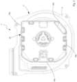
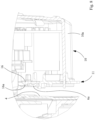
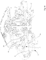
- a fan for air/gas mixing systems in burners of heating equipment constructed according to the invention.
- the fan 1 which is of the centrifugal type comprises an impeller 2 which has a main rotation axis designated X and which is provided with a plurality of radial blades 2a and is received in a volute or casing 3 which defines the conveying conduit for the fluid which is processed by the impeller between an axial intake zone and a tangential delivery zone.
- the volute 3 comprises a main volute body 3a to which there is fixed, for example, by means of screws, a closure plate 4 (made from sheet metal or diecast metal) and which is configured as a motor support plate.
- a closure plate 4 made from sheet metal or diecast metal
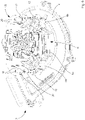
- the fan further comprises a motor support comprising a first metal frame 6 which is provided to be fixedly joined to the plate 4 and on which there is provision for mounting vibration damping elements 7.
- the motor 5 is therefore supported on the frame 6 with the damping elements 7 being interposed and being configured, for example, as silent block cylinders of the type conventional per se.
- a motor control printed circuit board which is positioned near the motor itself, preferably in a position above the motor, that is to say, at a side axially opposite the frame 6 with respect to the motor.
- the printed circuit board 8 is fixed, for example, screwed, to a stationary portion 5b of the motor 5.
- the portion 5b can be constructed in the form of a collar which is fixedly joined to the stator casing of the motor, from which a series of bridges 5c (three of them in the example described) which carry respective mushroom-like extension pieces 5d which are used for engaging in the respective members of the damping elements extend radially.
- cooling fan which is intended to be keyed to the motor shaft 5a at the opposite side of the motor with respect to the impeller.
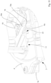
- the fan 1 further comprises a protection and containment cap 10 of the board/motor assembly, which has an open box-like formation with lateral walls 10a which extend upwards from a base wall 10b.
- the base wall 10b has a peripheral formation which is substantially quadrilateral for defining four lateral walls which are mutually connected.
- the cap 10 is advantageously produced from a plastics material with electrical insulation characteristics.
- the fan comprises a second frame 11 which is produced from plastics material identical to or compatible with the plastics material of the cap.
- the frame 11 can be connected to the metal frame 6 of the motor support and further comprises interconnection means and counter-means which are provided on the cap 10 and on the second frame 11, respectively, and which mutually cooperate in order to fix the cap to the fan by means of the second frame.
- the interconnection means and counter-means are further configured to preferably produce a connection with snap-fitting interlocking between the cap and the second frame.
- the interconnection means and counter-means comprise a plurality of through-openings 12 which extend through the second frame 11 and a corresponding plurality of interlocking extension pieces 13 which project from the cap and which are formed in such positions that each opening 12 is provided for the insertion of a corresponding interlocking extension piece 13 when the cap 10 is connected to the frame 11.
- Each extension piece 13 advantageously has at its own free end a toothed formation 14 which is capable of engaging with snap-fitting interlocking in the corresponding opening 12.
- the frame 11 has a base 11a with a small thickness with a peripheral profile with an open contour, on which there are located three sides which extend in continuation of each other and with pairs of contiguous sides which are substantially orthogonal to each other, each side having a counterpart at a respective free edge of a corresponding lateral wall of the cap.
- a pair of openings 12 which are arranged in such a position as to be engaged by a corresponding pair of extension pieces 13 which project from the free edge of the corresponding wall 10a of the cap so as to form the connection with snap-fitting interlocking between the cap 10 and the frame 11. This connection is therefore brought about by the total involvement of six extension pieces 13 in the respective six openings 12.
- column-like extension pieces which are all designated 20 and which extend in the same direction from the surface of the base facing the cap.
- the column-like extension pieces 20 are arranged along the sides of the base, particularly in the region of the openings 12, and are selected to have a number, formation and positioning suitable for allowing the interaction thereof, by means of contact, with the internal surfaces of the lateral walls of the cap, in order to generate a state of tension which is suitable for ensuring greater stability of connection between the cap and frame, in particular by taking up the occurrences of play of the connection between extension pieces 13 and corresponding openings 12.
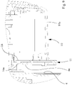
- the frame 11 further comprises engagement means with respect to the frame 6 in order to produce an interlocking securing action, of the removable type, between the frames themselves.
- the engagement means comprise at least one seat 15 on the frame 11 for engaging at least one portion 6a of the frame 6 and at least one fin 16 which projects from the frame 11 and which is capable of abutting the portion of the frame 6 so as to retain the frame 6 in the seat 15 and to mutually secure the frames.
- the engagement means produce a snap-fitting connection between the frames 6 and 11.
- the at least one fin 16 has at the free end thereof a toothed formation 16a which can be positioned against the portion 6a of the frame 6, prior to resilient flexion of the fin, during the relative engagement movement between the frames.
- the frame 6 is constructed from sheet metal which is cut or bent and which has a central annular flat portion which is delimited by a peripheral mount which has three portions 6a with a substantially rectilinear profile, each pair of contiguous portions 6a being connected in a corresponding portion 6b of the mount, each portion 6b having a respective through-hole 6c which is provided for mounting the corresponding cylindrical damping element 7.
- the edge of the hole 6c can be used for interlocking in a counter-shaped peripheral channel 7a of the damping element.
- Such a configuration provides for the three holes 6c to be positioned with an angular pitch of 120° relative to each other (about the main axis coincident with the axis X) and the portions 6a to extend along the respective sides of a hypothetical equilateral triangular profile.
- the frame 6 is fixedly joined to the plate 4 by means of plastic deformation of a portion of the central flat portion against a surface portion of the plate. Following the relative fixing thereof, the mount of the frame which has the portions 6a remains spaced apart from the plate 4, allowing the engagement of the frame 11 with the frame 6.
- a pair of seats 15 which are laterally opposite, each seat being delimited by surfaces 15a which can at least partially surround the corresponding portion 6a of the frame 6, during the relative engagement movement.
- Each fin 16, with the individual free toothed end thereof, is suitable for snap-fitting engagement and abutting the corresponding portion 6a of the frame 6.
- the notches 18 allow the centring of the frame 11 to be brought about relative to the frame 6 during the relative engagement step.
- the formation of the frame 11 described above is configured to allow the engagement of the frame 11 with the frame 6 in three different relative orientations, which are angularly arranged at 120° relative to each other (about the axis X).
- the Figures 4 to 6 there are shown the three relative positions between the frames which can be configured, respectively.
- the assembly constituted by the frame 11, motor 5 (and the stationary portion 5b thereof), control printed circuit board 8 and cap 10 can be fixed to the volute 3 in three different positions which are orientated at 120° relative to each other, allowing the cap 10 to be arranged, and in particular the opening 10c thereof for the access of the connection connector to the printed circuit board, in three different positions relative to the delivery section of the fan, with the advantageous result that, during installation, it is easier to select the most suitable positioning as a function of the dimensions and requirements of the plant encountered in situ.
- the solution proposed by the invention addresses the problem of counteracting the onset of vibrations and the consequent additional noise generated by the protection cap of the motor control printed circuit board and substantially correlated with the fixing system of the cap with respect to the fan.
- This additional noise component is added to other noise components which are emitted by the fan in the entire range of operation, in particular it is added to a relevant component connected with the type of motor used, typically, for example, a brushless monophase motor with a permanent magnet, the cause of which is a result of the tuning of the harmonics of the drive torque generated by the motor and the structural resonance frequencies of the mechanical components which constitute the fan itself.
- the monophase brushless motor with a permanent magnet installed in centrifugal fans is typically actuated by means of an inverter device with a control technique which provides for the motor to be supplied with an electric voltage with a square-wave profile.
- the motor With this control, the motor generates a drive torque with a range characterized by a wide number of harmonics.
- This feature together with the fact that the harmonics vary the amplitude and frequency thereof when the speed of the motor varies, brings about a substantial increase in the probability of having tuning of the harmonics of the drive torque with the structural resonance frequencies of the components of the fan and this effect of tuning is one of the causes of the acoustic noise emitted by the fan. Therefore, the problem is to substantially reduce the number of tunings between torque harmonics and resonance frequencies because such a reduction translates into a reduction of sound emission and therefore a reduction of the mean noise level.
- a solution which addresses this problem provides for a voltage with a sinusoidal profile to be supplied to the motor by the inverter.
- Such a solution allows a reduction, including up to complete elimination, of the amplitude of all the harmonics of the drive torque greater than the first one and therefore a reduction in the probability that there will be tuning with the structural resonance frequencies.
- This control technique with respect to the technique with voltage with a square profile, it is possible to substantially reduce the mean acoustic noise emitted by the fan over the entire operating range.
- the present invention addresses this specific problem and achieves the objectives proposed while affording a number of advantages compared with the known solutions.
- a first advantage involves the fact that the provision according to the invention of a fixing frame for the cap produced from the same material as the cap or from a material compatible with the material of the cap (advantageously, a plastics material with electrical insulation characteristics) prevents the onset of different thermal expansions which are connected with the temperature of operation of the fan and which are typically responsible for causing vibrations with a resultant generation of noise sound waves.
- Another advantage is that the fixing frame for the cap is engaged with the motor support plate for closing the volute, which plate is detached from the vibrations generated by the operation of the fan, as a result of the action of the vibration damping elements interposed between the motor and plate, consequently also detaching the cap from the above-mentioned vibrations.
- Another advantage is connected with the fact that the protection and containment cap of the printed circuit board is secured to the frame without additional fixing elements over more than half of the extent of the peripheral connection profile, thereby effectively limiting the deformation susceptible to vibrations of the cap itself, this deformation in fact being able to be the cause of sound waves being generated.
- connection of the cap to the frame without additional fixing elements is further advantageous in terms of reducing assembly costs and times along the production line of the fan, in addition to the fact that the use of tools is not needed.
- connection provided between the cap and the frame in the assembly step is of a resilient type (interlocking with snap-fitting engagement), therefore it does not have any tension forces once the final engagement condition is reached.
- Such a connection further does not have assembly conditions which can become degraded over time and during the service-life of the fan.
Landscapes
- Engineering & Computer Science (AREA)
- Mechanical Engineering (AREA)
- General Engineering & Computer Science (AREA)
- Structures Of Non-Positive Displacement Pumps (AREA)
- Gas Burners (AREA)
Claims (11)
- Lüfter für Luft/Gas-Mischsysteme in Brennern von Heizungsanlagen, umfassend:- ein Lüfterrad (2), das in einem Spiralgehäuse (3) aufgenommen ist, das mit einer Motorträgerplatte (4) versehen ist,- einen Motor (5), auf dessen Welle (5a) das Laufrad (2) aufgekeilt ist,- einen Motorträger mit einem ersten Metallrahmen (6) zur Montage von Schwingungsdämpfungselementen (7), wobei der erste Metallrahmen (6) fest mit der Motorträgerplatte (4) verbunden ist, wobei der Motor (5) auf dem ersten Metallrahmen (6) mit den Schwingungsdämpfungselementen (7), die dazwischen angeordnet sind, abgestützt ist,- eine Leiterplattenplatine (8) für die Motorsteuerung (5), die in der Nähe des Motors positioniert ist,- eine Schutz- und Einschlusskappe (10) der Platinen-/Motoranordnung,- dadurch gekennzeichnet, dass die Kappe (10) aus Kunststoffmaterial hergestellt ist und dadurch, dass sie einen zweiten Rahmen (11) aus Kunststoffmaterial aufweist, der mit dem ersten Metallrahmen (6) und Verbindungsmittel und Gegenmitteln verbunden werden kann, die jeweils an der Kappe (10) und am zweiten Rahmen (11) vorgesehen sind, und die wechselseitig zusammenwirken, um die Kappe mittels des zweiten Rahmens am Lüfter zu fixieren.
- Lüfter nach Anspruch 1, wobei die Verbindungsmittel und Gegenmittel eine lösbare Verbindung zwischen der Kappe (10) und dem zweiten Rahmen (11) herstellen.
- Lüfter nach Anspruch 1 oder Anspruch 2, wobei die Verbindungsmittel und Gegenmittel eingerichtet sind, um eine Verbindung mit Schnappverriegelung herzustellen.
- Lüfter nach Anspruch 3, wobei die Verbindungsmittel und Gegenmittel eine Mehrzahl von Durchgangsöffnungen (12) im zweiten Rahmen (11) und eine jeweilige Mehrzahl von verriegelbaren Verlängerungsstücken (13) aufweisen, die von der Kappe hervorstehen (10), wobei jede Öffnung (12) zum Einsetzen eines jeweiligen verriegelbaren Verlängerungsstücks (13) vorgesehen ist.
- Lüfter nach Anspruch 4, wobei jedes der Verlängerungsstücke (13) ein freies Ende aufweist, das eine Verzahnung (14) zum Einrasten mit der Schnappverriegelung in die entsprechende Öffnung (12) des zweiten Rahmens (11) trägt.
- Lüfter nach einem oder mehreren der vorhergehenden Ansprüche, wobei der zweite Rahmen (11) Mittel zum Eingriff mit dem ersten Rahmen (6) aufweist, um zwischen den ersten und zweiten Rahmen eine entfernbare Verriegelungsmaßnahme zu erzeugen.
- Lüfter nach Anspruch 6, wobei die Eingriffsmittel zumindest einen Sitz (15) am zweiten Rahmen (11) zum Eingriff mit zumindest einem Abschnitt (6a) des ersten Rahmens (6) und zumindest einer Rippe (16) aufweisen, die vom zweiten Rahmen (11) hervorsteht und die in der Lage ist, am Abschnitt (6a) des ersten Rahmens (6) anzuliegen, um so den ersten Rahmen im Sitz (15) des zweiten Rahmens zu halten und die Rahmen gegenseitig zu sichern.
- Lüfter nach Anspruch 7, wobei die Eingriffsmittel eine Schnappverriegelung zwischen den ersten (6) und zweiten (11) Rahmen herstellen.
- Lüfter nach Anspruch 7 oder Anspruch 8, wobei die ersten und zweiten Rahmen (6, 11) jeweils derartige Ausbildungen aufweisen, dass der zweite Rahmen (11) mit dem ersten Rahmen (6) in mehr als einer Position, die in Bezug auf den ersten Rahmen ausgerichtet ist, in Eingriff gebracht werden kann.
- Lüfter nach Anspruch 9, wobei zwischen dem ersten Rahmen (6) und dem zweiten Rahmen (11) drei relative Eingriffspositionen vorgesehen sind, die in einem Winkel von 120° relativ zueinander um eine Hauptachse (X) des ersten Rahmens (6) ausgerichtet sind.
- Lüfter nach einem oder mehreren der vorhergehenden Ansprüche, wobei die Kappe (10) aus elektrisch isolierendem Material hergestellt ist.
Applications Claiming Priority (1)
| Application Number | Priority Date | Filing Date | Title |
|---|---|---|---|
| IT102020000012616A IT202000012616A1 (it) | 2020-05-27 | 2020-05-27 | Ventilatore per sistemi di miscelazione aria-gas in bruciatori di apparecchi di riscaldamento |
Publications (2)
| Publication Number | Publication Date |
|---|---|
| EP3916243A1 EP3916243A1 (de) | 2021-12-01 |
| EP3916243B1 true EP3916243B1 (de) | 2023-03-08 |
Family
ID=72178966
Family Applications (1)
| Application Number | Title | Priority Date | Filing Date |
|---|---|---|---|
| EP21174457.8A Active EP3916243B1 (de) | 2020-05-27 | 2021-05-18 | Gebläse für luft-gas-mischsysteme in brennern von heizungsanlagen |
Country Status (3)
| Country | Link |
|---|---|
| EP (1) | EP3916243B1 (de) |
| IT (1) | IT202000012616A1 (de) |
| PL (1) | PL3916243T3 (de) |
Cited By (1)
| Publication number | Priority date | Publication date | Assignee | Title |
|---|---|---|---|---|
| TWI856876B (zh) * | 2023-11-16 | 2024-09-21 | 英業達股份有限公司 | 散熱風扇模組 |
Family Cites Families (4)
| Publication number | Priority date | Publication date | Assignee | Title |
|---|---|---|---|---|
| DE10204037C5 (de) * | 2002-02-01 | 2009-07-23 | Ebm-Papst Landshut Gmbh | Radialgebläse mit Elektromotor |
| CN101818746B (zh) * | 2009-02-27 | 2015-07-15 | 德昌电机(深圳)有限公司 | 预混式锅炉风机 |
| EP3064778B1 (de) * | 2015-03-06 | 2022-02-16 | ELICA S.p.A. | Radiallüfter mit luft-gas mischungsanordnung |
| DE202016103134U1 (de) * | 2016-06-14 | 2016-11-16 | Sit S.P.A. | Motorhalterung für einen Ventilator für Brenner mit Vormischung für Kessel und Ventilator einer solchen Motorhalterung |
-
2020
- 2020-05-27 IT IT102020000012616A patent/IT202000012616A1/it unknown
-
2021
- 2021-05-18 EP EP21174457.8A patent/EP3916243B1/de active Active
- 2021-05-18 PL PL21174457.8T patent/PL3916243T3/pl unknown
Cited By (1)
| Publication number | Priority date | Publication date | Assignee | Title |
|---|---|---|---|---|
| TWI856876B (zh) * | 2023-11-16 | 2024-09-21 | 英業達股份有限公司 | 散熱風扇模組 |
Also Published As
| Publication number | Publication date |
|---|---|
| PL3916243T3 (pl) | 2023-07-31 |
| IT202000012616A1 (it) | 2021-11-27 |
| EP3916243A1 (de) | 2021-12-01 |
Similar Documents
| Publication | Publication Date | Title |
|---|---|---|
| US6511288B1 (en) | Two piece blower housing with vibration absorbing bottom piece and mounting flanges | |
| JP4539659B2 (ja) | ファンモータ装置及び電子機器 | |
| CN101457762B (zh) | 轴流风扇单元 | |
| EP3916243B1 (de) | Gebläse für luft-gas-mischsysteme in brennern von heizungsanlagen | |
| CN108800315A (zh) | 空调器 | |
| US20090123306A1 (en) | Coupling element cooling arrangement | |
| JPH0246147A (ja) | 電気モータ組立体 | |
| KR101833146B1 (ko) | 진동 저감을 위한 모터 고정브라켓 | |
| CN111828389B (zh) | 保持装置和用于保持装置的热防护罩 | |
| KR102748007B1 (ko) | 새로운 구조의 스테이터 블록을 갖는 bldc 블로워 모터 | |
| EP3913284B1 (de) | Gas/luft-mischvorrichtung für einen gasbrenner | |
| KR102221701B1 (ko) | 소음저감형 팬모터고정장치 | |
| KR20240146402A (ko) | 결합 구조가 개선된 스테이터 블록을 갖는 bldc 블로워 모터 | |
| EP3330545B1 (de) | Radiallüfter | |
| CN210128393U (zh) | 风机及油烟机 | |
| JP3561633B2 (ja) | 送風機の気密保持装置 | |
| KR100783415B1 (ko) | 전동팬 | |
| CN113680224A (zh) | 气体燃烧器的气体/空气混合装置 | |
| JP2004162720A (ja) | 送風機の気密保持装置 | |
| CN223754303U (zh) | 叶轮和具有该叶轮的风扇 | |
| KR102748024B1 (ko) | 접지 구조가 개선된 스테이터 블록을 갖는 bldc 블로워 모터 | |
| KR102748019B1 (ko) | 에어 리크를 방지할 수 있는 bldc 블로워 모터 | |
| JPH10288186A (ja) | モータ内蔵型送風機 | |
| JP4213683B2 (ja) | 燃焼装置 | |
| JP4436868B2 (ja) | 電動モータを受容するための装置 |
Legal Events
| Date | Code | Title | Description |
|---|---|---|---|
| PUAI | Public reference made under article 153(3) epc to a published international application that has entered the european phase |
Free format text: ORIGINAL CODE: 0009012 |
|
| STAA | Information on the status of an ep patent application or granted ep patent |
Free format text: STATUS: THE APPLICATION HAS BEEN PUBLISHED |
|
| AK | Designated contracting states |
Kind code of ref document: A1 Designated state(s): AL AT BE BG CH CY CZ DE DK EE ES FI FR GB GR HR HU IE IS IT LI LT LU LV MC MK MT NL NO PL PT RO RS SE SI SK SM TR |
|
| B565 | Issuance of search results under rule 164(2) epc |
Effective date: 20211013 |
|
| STAA | Information on the status of an ep patent application or granted ep patent |
Free format text: STATUS: REQUEST FOR EXAMINATION WAS MADE |
|
| 17P | Request for examination filed |
Effective date: 20220504 |
|
| RBV | Designated contracting states (corrected) |
Designated state(s): AL AT BE BG CH CY CZ DE DK EE ES FI FR GB GR HR HU IE IS IT LI LT LU LV MC MK MT NL NO PL PT RO RS SE SI SK SM TR |
|
| GRAP | Despatch of communication of intention to grant a patent |
Free format text: ORIGINAL CODE: EPIDOSNIGR1 |
|
| STAA | Information on the status of an ep patent application or granted ep patent |
Free format text: STATUS: GRANT OF PATENT IS INTENDED |
|
| INTG | Intention to grant announced |
Effective date: 20220927 |
|
| GRAS | Grant fee paid |
Free format text: ORIGINAL CODE: EPIDOSNIGR3 |
|
| GRAA | (expected) grant |
Free format text: ORIGINAL CODE: 0009210 |
|
| STAA | Information on the status of an ep patent application or granted ep patent |
Free format text: STATUS: THE PATENT HAS BEEN GRANTED |
|
| AK | Designated contracting states |
Kind code of ref document: B1 Designated state(s): AL AT BE BG CH CY CZ DE DK EE ES FI FR GB GR HR HU IE IS IT LI LT LU LV MC MK MT NL NO PL PT RO RS SE SI SK SM TR |
|
| REG | Reference to a national code |
Ref country code: CH Ref legal event code: EP Ref country code: AT Ref legal event code: REF Ref document number: 1552734 Country of ref document: AT Kind code of ref document: T Effective date: 20230315 |
|
| REG | Reference to a national code |
Ref country code: IE Ref legal event code: FG4D |
|
| REG | Reference to a national code |
Ref country code: DE Ref legal event code: R096 Ref document number: 602021001560 Country of ref document: DE |
|
| REG | Reference to a national code |
Ref country code: LT Ref legal event code: MG9D |
|
| REG | Reference to a national code |
Ref country code: NL Ref legal event code: MP Effective date: 20230308 |
|
| P01 | Opt-out of the competence of the unified patent court (upc) registered |
Effective date: 20230613 |
|
| PG25 | Lapsed in a contracting state [announced via postgrant information from national office to epo] |
Ref country code: RS Free format text: LAPSE BECAUSE OF FAILURE TO SUBMIT A TRANSLATION OF THE DESCRIPTION OR TO PAY THE FEE WITHIN THE PRESCRIBED TIME-LIMIT Effective date: 20230308 Ref country code: NO Free format text: LAPSE BECAUSE OF FAILURE TO SUBMIT A TRANSLATION OF THE DESCRIPTION OR TO PAY THE FEE WITHIN THE PRESCRIBED TIME-LIMIT Effective date: 20230608 Ref country code: LV Free format text: LAPSE BECAUSE OF FAILURE TO SUBMIT A TRANSLATION OF THE DESCRIPTION OR TO PAY THE FEE WITHIN THE PRESCRIBED TIME-LIMIT Effective date: 20230308 Ref country code: LT Free format text: LAPSE BECAUSE OF FAILURE TO SUBMIT A TRANSLATION OF THE DESCRIPTION OR TO PAY THE FEE WITHIN THE PRESCRIBED TIME-LIMIT Effective date: 20230308 Ref country code: HR Free format text: LAPSE BECAUSE OF FAILURE TO SUBMIT A TRANSLATION OF THE DESCRIPTION OR TO PAY THE FEE WITHIN THE PRESCRIBED TIME-LIMIT Effective date: 20230308 Ref country code: ES Free format text: LAPSE BECAUSE OF FAILURE TO SUBMIT A TRANSLATION OF THE DESCRIPTION OR TO PAY THE FEE WITHIN THE PRESCRIBED TIME-LIMIT Effective date: 20230308 |
|
| REG | Reference to a national code |
Ref country code: AT Ref legal event code: MK05 Ref document number: 1552734 Country of ref document: AT Kind code of ref document: T Effective date: 20230308 |
|
| PG25 | Lapsed in a contracting state [announced via postgrant information from national office to epo] |
Ref country code: SE Free format text: LAPSE BECAUSE OF FAILURE TO SUBMIT A TRANSLATION OF THE DESCRIPTION OR TO PAY THE FEE WITHIN THE PRESCRIBED TIME-LIMIT Effective date: 20230308 Ref country code: NL Free format text: LAPSE BECAUSE OF FAILURE TO SUBMIT A TRANSLATION OF THE DESCRIPTION OR TO PAY THE FEE WITHIN THE PRESCRIBED TIME-LIMIT Effective date: 20230308 Ref country code: GR Free format text: LAPSE BECAUSE OF FAILURE TO SUBMIT A TRANSLATION OF THE DESCRIPTION OR TO PAY THE FEE WITHIN THE PRESCRIBED TIME-LIMIT Effective date: 20230609 Ref country code: FI Free format text: LAPSE BECAUSE OF FAILURE TO SUBMIT A TRANSLATION OF THE DESCRIPTION OR TO PAY THE FEE WITHIN THE PRESCRIBED TIME-LIMIT Effective date: 20230308 |
|
| PG25 | Lapsed in a contracting state [announced via postgrant information from national office to epo] |
Ref country code: SM Free format text: LAPSE BECAUSE OF FAILURE TO SUBMIT A TRANSLATION OF THE DESCRIPTION OR TO PAY THE FEE WITHIN THE PRESCRIBED TIME-LIMIT Effective date: 20230308 Ref country code: RO Free format text: LAPSE BECAUSE OF FAILURE TO SUBMIT A TRANSLATION OF THE DESCRIPTION OR TO PAY THE FEE WITHIN THE PRESCRIBED TIME-LIMIT Effective date: 20230308 Ref country code: PT Free format text: LAPSE BECAUSE OF FAILURE TO SUBMIT A TRANSLATION OF THE DESCRIPTION OR TO PAY THE FEE WITHIN THE PRESCRIBED TIME-LIMIT Effective date: 20230710 Ref country code: EE Free format text: LAPSE BECAUSE OF FAILURE TO SUBMIT A TRANSLATION OF THE DESCRIPTION OR TO PAY THE FEE WITHIN THE PRESCRIBED TIME-LIMIT Effective date: 20230308 Ref country code: CZ Free format text: LAPSE BECAUSE OF FAILURE TO SUBMIT A TRANSLATION OF THE DESCRIPTION OR TO PAY THE FEE WITHIN THE PRESCRIBED TIME-LIMIT Effective date: 20230308 Ref country code: AT Free format text: LAPSE BECAUSE OF FAILURE TO SUBMIT A TRANSLATION OF THE DESCRIPTION OR TO PAY THE FEE WITHIN THE PRESCRIBED TIME-LIMIT Effective date: 20230308 |
|
| PG25 | Lapsed in a contracting state [announced via postgrant information from national office to epo] |
Ref country code: SK Free format text: LAPSE BECAUSE OF FAILURE TO SUBMIT A TRANSLATION OF THE DESCRIPTION OR TO PAY THE FEE WITHIN THE PRESCRIBED TIME-LIMIT Effective date: 20230308 Ref country code: IS Free format text: LAPSE BECAUSE OF FAILURE TO SUBMIT A TRANSLATION OF THE DESCRIPTION OR TO PAY THE FEE WITHIN THE PRESCRIBED TIME-LIMIT Effective date: 20230708 |
|
| REG | Reference to a national code |
Ref country code: DE Ref legal event code: R097 Ref document number: 602021001560 Country of ref document: DE |
|
| PLBE | No opposition filed within time limit |
Free format text: ORIGINAL CODE: 0009261 |
|
| STAA | Information on the status of an ep patent application or granted ep patent |
Free format text: STATUS: NO OPPOSITION FILED WITHIN TIME LIMIT |
|
| PG25 | Lapsed in a contracting state [announced via postgrant information from national office to epo] |
Ref country code: MC Free format text: LAPSE BECAUSE OF FAILURE TO SUBMIT A TRANSLATION OF THE DESCRIPTION OR TO PAY THE FEE WITHIN THE PRESCRIBED TIME-LIMIT Effective date: 20230308 |
|
| REG | Reference to a national code |
Ref country code: BE Ref legal event code: MM Effective date: 20230531 |
|
| PG25 | Lapsed in a contracting state [announced via postgrant information from national office to epo] |
Ref country code: SI Free format text: LAPSE BECAUSE OF FAILURE TO SUBMIT A TRANSLATION OF THE DESCRIPTION OR TO PAY THE FEE WITHIN THE PRESCRIBED TIME-LIMIT Effective date: 20230308 Ref country code: MC Free format text: LAPSE BECAUSE OF FAILURE TO SUBMIT A TRANSLATION OF THE DESCRIPTION OR TO PAY THE FEE WITHIN THE PRESCRIBED TIME-LIMIT Effective date: 20230308 Ref country code: LU Free format text: LAPSE BECAUSE OF NON-PAYMENT OF DUE FEES Effective date: 20230518 Ref country code: DK Free format text: LAPSE BECAUSE OF FAILURE TO SUBMIT A TRANSLATION OF THE DESCRIPTION OR TO PAY THE FEE WITHIN THE PRESCRIBED TIME-LIMIT Effective date: 20230308 |
|
| 26N | No opposition filed |
Effective date: 20231211 |
|
| REG | Reference to a national code |
Ref country code: IE Ref legal event code: MM4A |
|
| PG25 | Lapsed in a contracting state [announced via postgrant information from national office to epo] |
Ref country code: IE Free format text: LAPSE BECAUSE OF NON-PAYMENT OF DUE FEES Effective date: 20230518 |
|
| PG25 | Lapsed in a contracting state [announced via postgrant information from national office to epo] |
Ref country code: IE Free format text: LAPSE BECAUSE OF NON-PAYMENT OF DUE FEES Effective date: 20230518 |
|
| PG25 | Lapsed in a contracting state [announced via postgrant information from national office to epo] |
Ref country code: FR Free format text: LAPSE BECAUSE OF NON-PAYMENT OF DUE FEES Effective date: 20230531 Ref country code: BE Free format text: LAPSE BECAUSE OF NON-PAYMENT OF DUE FEES Effective date: 20230531 |
|
| PGFP | Annual fee paid to national office [announced via postgrant information from national office to epo] |
Ref country code: PL Payment date: 20240422 Year of fee payment: 4 |
|
| PG25 | Lapsed in a contracting state [announced via postgrant information from national office to epo] |
Ref country code: BG Free format text: LAPSE BECAUSE OF FAILURE TO SUBMIT A TRANSLATION OF THE DESCRIPTION OR TO PAY THE FEE WITHIN THE PRESCRIBED TIME-LIMIT Effective date: 20230308 |
|
| PG25 | Lapsed in a contracting state [announced via postgrant information from national office to epo] |
Ref country code: BG Free format text: LAPSE BECAUSE OF FAILURE TO SUBMIT A TRANSLATION OF THE DESCRIPTION OR TO PAY THE FEE WITHIN THE PRESCRIBED TIME-LIMIT Effective date: 20230308 |
|
| REG | Reference to a national code |
Ref country code: CH Ref legal event code: PL |
|
| PG25 | Lapsed in a contracting state [announced via postgrant information from national office to epo] |
Ref country code: CH Free format text: LAPSE BECAUSE OF NON-PAYMENT OF DUE FEES Effective date: 20240531 |
|
| PGFP | Annual fee paid to national office [announced via postgrant information from national office to epo] |
Ref country code: DE Payment date: 20250423 Year of fee payment: 5 |
|
| PGFP | Annual fee paid to national office [announced via postgrant information from national office to epo] |
Ref country code: IT Payment date: 20250423 Year of fee payment: 5 |
|
| PG25 | Lapsed in a contracting state [announced via postgrant information from national office to epo] |
Ref country code: CY Free format text: LAPSE BECAUSE OF FAILURE TO SUBMIT A TRANSLATION OF THE DESCRIPTION OR TO PAY THE FEE WITHIN THE PRESCRIBED TIME-LIMIT; INVALID AB INITIO Effective date: 20210518 |
|
| PGFP | Annual fee paid to national office [announced via postgrant information from national office to epo] |
Ref country code: TR Payment date: 20250428 Year of fee payment: 5 |
|
| PG25 | Lapsed in a contracting state [announced via postgrant information from national office to epo] |
Ref country code: HU Free format text: LAPSE BECAUSE OF FAILURE TO SUBMIT A TRANSLATION OF THE DESCRIPTION OR TO PAY THE FEE WITHIN THE PRESCRIBED TIME-LIMIT; INVALID AB INITIO Effective date: 20210518 |
|
| GBPC | Gb: european patent ceased through non-payment of renewal fee |
Effective date: 20250518 |