EP3915909B1 - Verfahren zum sichern eines logistikbereichs - Google Patents
Verfahren zum sichern eines logistikbereichs Download PDFInfo
- Publication number
- EP3915909B1 EP3915909B1 EP21173668.1A EP21173668A EP3915909B1 EP 3915909 B1 EP3915909 B1 EP 3915909B1 EP 21173668 A EP21173668 A EP 21173668A EP 3915909 B1 EP3915909 B1 EP 3915909B1
- Authority
- EP
- European Patent Office
- Prior art keywords
- vehicle
- module
- zone
- status indicator
- processing unit
- Prior art date
- Legal status (The legal status is an assumption and is not a legal conclusion. Google has not performed a legal analysis and makes no representation as to the accuracy of the status listed.)
- Active
Links
Images







Classifications
-
- G—PHYSICS
- G06—COMPUTING OR CALCULATING; COUNTING
- G06Q—INFORMATION AND COMMUNICATION TECHNOLOGY [ICT] SPECIALLY ADAPTED FOR ADMINISTRATIVE, COMMERCIAL, FINANCIAL, MANAGERIAL OR SUPERVISORY PURPOSES; SYSTEMS OR METHODS SPECIALLY ADAPTED FOR ADMINISTRATIVE, COMMERCIAL, FINANCIAL, MANAGERIAL OR SUPERVISORY PURPOSES, NOT OTHERWISE PROVIDED FOR
- G06Q50/00—Information and communication technology [ICT] specially adapted for implementation of business processes of specific business sectors, e.g. utilities or tourism
- G06Q50/10—Services
- G06Q50/26—Government or public services
- G06Q50/265—Personal security, identity or safety
-
- B—PERFORMING OPERATIONS; TRANSPORTING
- B65—CONVEYING; PACKING; STORING; HANDLING THIN OR FILAMENTARY MATERIAL
- B65G—TRANSPORT OR STORAGE DEVICES, e.g. CONVEYORS FOR LOADING OR TIPPING, SHOP CONVEYOR SYSTEMS OR PNEUMATIC TUBE CONVEYORS
- B65G69/00—Auxiliary measures taken, or devices used, in connection with loading or unloading
- B65G69/28—Loading ramps; Loading docks
- B65G69/287—Constructional features of deck or surround
- B65G69/2876—Safety or protection means, e.g. skirts
- B65G69/2882—Safety or protection means, e.g. skirts operated by detectors or sensors
-
- B—PERFORMING OPERATIONS; TRANSPORTING
- B66—HOISTING; LIFTING; HAULING
- B66F—HOISTING, LIFTING, HAULING OR PUSHING, NOT OTHERWISE PROVIDED FOR, e.g. DEVICES WHICH APPLY A LIFTING OR PUSHING FORCE DIRECTLY TO THE SURFACE OF A LOAD
- B66F17/00—Safety devices, e.g. for limiting or indicating lifting force
- B66F17/003—Safety devices, e.g. for limiting or indicating lifting force for fork-lift trucks
-
- G—PHYSICS
- G06—COMPUTING OR CALCULATING; COUNTING
- G06Q—INFORMATION AND COMMUNICATION TECHNOLOGY [ICT] SPECIALLY ADAPTED FOR ADMINISTRATIVE, COMMERCIAL, FINANCIAL, MANAGERIAL OR SUPERVISORY PURPOSES; SYSTEMS OR METHODS SPECIALLY ADAPTED FOR ADMINISTRATIVE, COMMERCIAL, FINANCIAL, MANAGERIAL OR SUPERVISORY PURPOSES, NOT OTHERWISE PROVIDED FOR
- G06Q10/00—Administration; Management
- G06Q10/08—Logistics, e.g. warehousing, loading or distribution; Inventory or stock management
Definitions
- the invention relates to a method for securing a logistics area, in particular a loading zone, comprising the steps: monitoring a control zone, which is a sub-area of a first three-dimensional electromagnetic field provided by a control antenna unit and determining whether a first vehicle module is in the Control zone is located, wherein the vehicle module is mounted on a first vehicle, in particular forklift truck and/or autonomously driving vehicle, and tuned to the control antenna unit.
- a loading zone for loading and unloading transport vehicles is usually at about the same height as a loading area of a transport vehicle, which enables loading and unloading to be carried out as quickly as possible.
- Loading ramps are usually provided in order to bridge a gap between the loading zone and the loading area of the transport vehicle.
- loading ramps can be accessed manually loading ramp or be electrically, pneumatically or hydraulically driven.
- modern loading ramps are often equipped with lips that are intended to provide a transition between the loading ramp and the loading area that is as continuous as possible, an edge of the loading ramp usually has to be driven over by an industrial truck when loading and unloading the vehicle.
- Driving over these edges too quickly can cause a variety of problems.
- the tires of an industrial truck are subject to increased wear if the edge between the loading ramp and the loading area is driven over too quickly. This wear causes failures of industrial trucks and increased maintenance costs.
- noise is generated, which, particularly in densely populated areas, can lead to a lack of acceptance of the logistics area and to health problems for the staff.
- driving over the edge can cause vibrations, which can lead to goods being transported falling down and/or damage to sensitive goods being transported.
- the edge can cause an impact on the vehicle, which translates into human vibrations that can damage the health of an industrial truck driver in the event of long-term and regular exposure.
- Another problem in the logistics sector is damage to infrastructure, transport vehicles and industrial trucks caused by the industrial truck lifting unit being too high. If, for example, a lifting mast of a forklift that is provided for lifting goods to be transported is raised too far while the forklift is on a loading area of a transport vehicle, a cover of the loading area of the transport vehicle can be damaged.
- DE 20 2018 105 041 U1 of the present applicant discloses a gate security system for preventing collisions between a vehicle and a gate.
- a gate module located on the gate defines a gate warning zone and determines whether a matched vehicle module is within the gate warning zone.
- a gate processing unit is further configured to send a brake signal to the vehicle module to brake a vehicle on which the vehicle module is mounted.
- DE 20 2018 105 041 U1 discloses a method according to the preamble of claim 1 and a system according to the preamble of claim 8.
- the present applicant discloses a method for warning persons in traffic, with a warning zone being monitored and it being determined whether a warning module is located within the warning zone.
- a warning signal may be issued in response to determining the warning module within the warning zone.
- the object of the present invention is therefore to provide a method that is suitable for securing a logistics area and offers improved security compared to the prior art.
- the invention solves this problem by the method according to claim 1.
- the security status indicator is thus maintained during operation until the first vehicle module or the first vehicle enters or is located in the release zone. As soon as the first vehicle module has been registered in the control zone, this first vehicle module no longer needs to be monitored, which means that the method can be carried out as simply as possible. Furthermore, a failsafe increased because the security status indicator is also set if a control module, which preferably defines the control zone, should have an error after the security status indicator was set. For example, the security status indicator can be set even if the control module fails and no longer defines a control zone.
- the method further includes: setting a vehicle security status indicator in a first vehicle control unit of the first vehicle in response to the determination of the first vehicle module in the control zone and/or in response to the setting of the security status indicator in the first vehicle processing unit, and maintaining the vehicle safety status indicator in the first vehicle control unit of the first vehicle even if the first vehicle module leaves the control zone and/or if the first vehicle module has a fault.
- a failure safety can be further increased by an additional setting of a vehicle safety status indicator.
- the vehicle security status indicator is maintained even if the first vehicle module becomes damaged and/or has a fault.
- the steps of the method can also advantageously be achieved in that only an entry of the first vehicle has to be detected and no permanent monitoring of a vehicle located in the control zone is necessary.
- the invention is based on the finding that the logistic areas to be secured often have only a single entrance and therefore only this entrance has to be monitored in order to avoid collisions.
- a spatial extent of the control zone can be restricted without reducing the functionality of the method. For example, if the zone of control is chosen to cover a loading dock, the security status indicator will be set and maintained even if the first vehicle is on a truck bed. In this case, the entire loading area of the vehicle does not have to be covered by the control zone, as a result of which the processing efficiency of a system carrying out the method can be increased.
- the release zone is located adjacent to the control zone. Further preferably, the release zone and the control zone can also be designed to overlap.
- the security status indicator is preferably only deleted if it is determined that the first vehicle module is located exclusively in the release zone.
- the control zone and the release zone are formed at a distance from one another.
- the release zone can be arranged in a gate area that forms a transition between an unloading area with loading docks and a main storage area of a warehouse.
- the step of determining whether the first vehicle module is in the control zone comprises: determining, by the control processing unit, that the first vehicle module is in the control zone; sending a zone of control configuration to the first vehicle module, and the first vehicle module determining whether the first vehicle module is in the zone of control using the received zone of control configuration.
- the configuration of the control zone includes at least a three-dimensional shape of the control zone, in particular a projection of the control zone onto an area on which vehicles are driving.
- the security status indicator preferably characterizes a specific status of the first vehicle processing unit and/or a computer program running on the vehicle processing unit.
- the security status indicator is particularly preferably a digital status indicator, which can also be referred to as a flag.
- the security status indicator determines an operational status of the vehicle processing unit.
- Monitoring a control zone preferably comprises the steps of generating a first three-dimensional electromagnetic field by means of a control antenna unit, defining the control zone, which is a sub-area of the first three-dimensional electromagnetic field, by means of a control processing unit, and monitoring the control zone by the control processing unit.
- the second status indicator preferably determines a second operating state of the vehicle processing unit, which particularly preferably corresponds to a regular operating state.
- the second vehicle indicator is used to identify the first vehicle.
- goods tracking can be facilitated by means of the second vehicle indicator.
- the method also includes: Restricting at least one degree of freedom of movement of the first vehicle when the safety status indicator is set in the first vehicle processing unit.
- the first vehicle module is preferably connected to a controller of the first vehicle, with the A method comprising the steps of providing a constraint signal to the controller of the first vehicle using the first vehicle module. It should be understood that more than one degree of freedom of movement of the first vehicle can also be restricted when the safety status indicator is set.
- the method further includes: releasing the at least one degree of freedom of movement of the first vehicle when the safety status indicator is deleted from the first vehicle processing unit.
- the method also preferably has: releasing the at least one degree of freedom of movement of the first vehicle when the second status indicator is set in the first vehicle processing unit.
- another degree of freedom is restricted or the at least one degree of freedom of movement of the first vehicle is restricted in a different way when the second status indicator is set.
- a first degree of freedom of movement of the vehicle can be restricted and a second degree of freedom of movement can be restricted less intensively, for example only to 50% of the maximum restriction, or less.
- an achievable maximum speed of the vehicle can be increased and a maximum steering angle of the vehicle can be released or its limitation removed.
- the degree of freedom of movement is preferably selected from one of the following parameters: driving speed of the vehicle, curve radius, lifting height of a lifting unit of the vehicle, acceleration of the vehicle, possible direction of travel of the first vehicle, in particular forward travel and/or reverse travel of the first vehicle, maximum achievable travel speed when driving forward first vehicle, maximum driving speed that can be achieved when reversing the first vehicle, approved movement range of the vehicle.
- driving speed of the vehicle curve radius
- lifting height of a lifting unit of the vehicle acceleration of the vehicle
- possible direction of travel of the first vehicle in particular forward travel and/or reverse travel of the first vehicle
- maximum achievable travel speed when driving forward first vehicle maximum driving speed that can be achieved when reversing the first vehicle, approved movement range of the vehicle.
- limiting the minimum curve radius and/or maximum curve radius of the vehicle can also avoid damage caused by sudden strong steering movements. Limiting a maximum acceleration of the vehicle prevents cargo from falling. Furthermore, a lifting height of a lifting unit of the vehicle can be restricted. For example, a Lifting mast of a forklift does not exceed a maximum height, which avoids damage to covers of loading areas of transport vehicles or transport units such as containers or collisions with loading gates. Furthermore, a released range of movement of the vehicle can also be defined. For example, access by the vehicle to a predetermined sub-area of the logistics area can be restricted and/or prevented if the first security status indicator is set. This is particularly desirable when the vehicle is an autonomous vehicle.
- the step of determining whether a first vehicle module is located in the first control zone is preferably performed by the first vehicle module.
- the determination of whether a first vehicle is located in the first control zone is carried out by the control module.
- the control module is then designed to provide a signal to the vehicle module by means of the control module antenna unit, which signal represents the presence of the vehicle module in the control zone.
- the method further includes: defining a first vehicle warning zone for the first vehicle, which is a partial area of a third electromagnetic field provided by a first vehicle antenna unit on the first vehicle; determining whether a second vehicle module that is matched to the first vehicle warning zone is located in the first vehicle warning zone; detecting a status indicator set in a second vehicle processing unit of the second vehicle module; comparing the status indicator set in the first vehicle processing unit to the status indicator set in the second vehicle processing unit; and performing at least one follow-up operation when the status indicator set in the second vehicle processing unit is different than or equal to the status indicator set in the first vehicle processing unit.
- a vehicle warning zone can therefore also be defined for the first vehicle.
- the status indicators set in the first vehicle processing unit and the second vehicle processing unit By comparing the status indicators set in the first vehicle processing unit and the second vehicle processing unit, vehicles that are or have been in the area of the control zone and vehicles that are not in the control zone or are within the release zone located, be distinguished. It can thus be achieved in an advantageous manner that the follow-up operation is only carried out if the status indicators set in the vehicle modules differ, with the status indicators also differing if only in one of the processing units a status indicator is set. For example, if the control zone covers a loading dock, the security status indicator will be set when the vehicle enters the bed of a transport vehicle. Several transport vehicles are often positioned next to each other and are unloaded at the same time.
- the safety status indicator is also set in a second vehicle processing unit when driving onto its loading area.
- a status indicator of the first vehicle processing unit and a status indicator of the second vehicle processing unit match and no follow-up operation is performed.
- a plurality of first vehicle warning zones can preferably also be defined for the first vehicle, which particularly preferably have varying geometric definitions. For example, a smaller circular vehicle warning zone may be surrounded by a larger vehicle warning zone.
- the method further comprises: changing a configuration of the first vehicle warning zone in response to determining the first vehicle module in the control zone and/or changing a configuration of the first vehicle warning zone when it is determined that the first vehicle module is in the clearance zone.
- the configuration of the vehicle warning zone comprises at least one geometric configuration of the vehicle warning zone. In this way, a size of the vehicle warning zone can be reduced, preferably in response to the determination of the first vehicle module in the control zone.
- the geometric configuration can also be changed.
- the first vehicle warning zone may be changed from a circular vehicle warning zone defined uniformly around the vehicle to an elongated forward vehicle warning zone in the direction of travel of the vehicle when the first vehicle module is detected in the control zone.
- the method preferably further comprises: sending a status indicator set in the first vehicle processing unit of the first vehicle module, preferably to the second vehicle module, if it is determined that the second vehicle module is in the first vehicle warning zone.
- the first vehicle module is preferably configured to send a configuration of the first vehicle warning zone to the second vehicle module if it is determined that the second vehicle module is located in the first vehicle warning zone.
- the method particularly preferably includes the step of sending the status indicator set in the first vehicle processing unit to the second vehicle module if it is determined that the second vehicle module is within the first vehicle warning zone.
- the method further includes: defining a second vehicle warning zone for the second vehicle, which is a sub-area of a fourth three-dimensional electromagnetic field provided by a second vehicle antenna unit; receiving a configuration of the second vehicle warning zone of the second vehicle at the first vehicle module; determining, by the first vehicle module, whether the first vehicle module is in the second vehicle warning zone.
- a status indicator set in the first vehicle processing unit is particularly preferably only sent if it is determined that the first vehicle module is located in the second vehicle warning zone. It should be understood that preferably both vehicle modules can be designed to send a configuration of the respective warning zone defined by this vehicle module. Furthermore, both vehicle modules are preferably designed to transmit the respectively set status indicator.
- the method preferably also includes: determining whether the first vehicle module and the second vehicle module are approaching one another. Both the first vehicle module and the second vehicle module are preferably designed to determine whether the first vehicle module and the second module are approaching one another. However, it can also be provided that only the first vehicle module or only the second vehicle module is designed to determine that the vehicle modules are approaching one another. The at least one follow-up operation is preferably only carried out if it is determined that the first vehicle module and the second vehicle module are approaching one another.
- the follow-up operation has at least one of the following steps: providing a warning signal to the first vehicle; providing a warning signal at the second vehicle; Limiting at least one degree of freedom of movement of the first vehicle; and/or restricting at least one degree of freedom of movement of the second vehicle.
- the restriction of the degree of freedom of movement of the first vehicle and the restriction of the degree of freedom of movement of the second vehicle can be identical.
- different degrees of freedom of movement of the vehicles are restricted, or that an identical degree of freedom of movement is restricted to different degrees.
- the constraint on the degree of freedom of movement when approaching is identical to the constraint on the degree of freedom of movement of the vehicle when the safety status indicator is set.
- the first control zone preferably covers a transition area between a loading ramp and a transport vehicle to be loaded or unloaded. However, it can also be provided that the control zone covers an access area to an aisle, in particular an aisle formed by shelves.
- the method includes: determining whether the first vehicle module mounted on the first vehicle is located on a loading area of the transport vehicle. It is preferably determined that the first vehicle module is on the loading area of the transport vehicle when the vehicle module leaves the control zone at a predefined border area.
- the method particularly preferably has the step: determining a direction of travel of the vehicle when the first vehicle module leaves the control zone. For example, it can be determined that the vehicle is arranged on a loading area of the transport vehicle when the vehicle module leaves the control zone in a specific direction.
- the method further includes: determining whether the transport vehicle is moving; and at least one of the steps: providing a warning signal at the first vehicle module; braking the first vehicle to a stop; if it is determined that the transport vehicle is moving and the first vehicle module is on the bed of the transport vehicle.
- the method has: determining whether the first vehicle module mounted on the first vehicle leaves the loading area of the transport vehicle. In this way it can be ensured that before the transport vehicle departs, all vehicles have left the loading area, as a result of which accidents and thefts can be avoided.
- the method preferably also includes: determining a dwell time of the first vehicle module on the loading area of the transport vehicle.
- the method particularly preferably also has: comparing the determined dwell time of the first vehicle module on the loading area with a predefined dwell time limit value and also preferably providing a dwell time warning signal if the determined dwell time exceeds the dwell time limit value. For example, a dwell time of a vehicle module that exceeds the dwell time limit value can indicate an emergency situation on the loading area and thus increase safety. Furthermore, theft of vehicles can be avoided.
- the method further comprises: capturing an image of the first vehicle, the transport vehicle, and/or a load of the first vehicle when it is determined that the first vehicle module leaves the loading area of the transport vehicle. Capturing an image enables documentation of the condition of the transport vehicle, the load and/or the first vehicle at the time of loading or unloading, which means that any damage can be traced. For example, it can be determined whether a shipment of goods was already damaged upon delivery.
- the method preferably also has: determining an open state of a gate arranged in the first control zone, the step of monitoring a first control zone only taking place if it is determined that the gate is open. In this way, it can be achieved in an advantageous manner that the safety status indicator is set only when driving through the gate. If, on the other hand, the gate is closed, it is usually not necessary to set the security status indicator. Furthermore, a closed door generally does not have to be monitored, which means that resources can be saved.
- the invention solves the task mentioned at the outset with a logistics security system for securing a logistics area, with a control module, having a control antenna unit, with at least one first control antenna, which is designed to be in a predetermined spatial relationship to a loading zone of the logistics area and to generate a first three-dimensional electromagnetic field, a control processing unit connected to the control antenna unit and adapted to define at least one control zone for the loading zone, which is a sub-area of the first three-dimensional electromagnetic field; a release module, comprising a release antenna unit, with at least a first release antenna, which is designed to generate a second three-dimensional electromagnetic field, a release processing unit connected to the release antenna unit, which is adapted to at least one release zone that is a portion of the second three-dimensional electromagnetic field, and with a first vehicle module for a first vehicle comprising a first vehicle antenna unit, with at least one first vehicle antenna adapted to be in a predetermined spatial relationship on the first to be mounted on a vehicle and to generate a
- the control antenna unit preferably has a number of control antennas, with the first control processing unit being particularly preferably designed to define a geometric shape of the control zone.
- the vehicle antenna unit and/or the enabling antenna unit can also preferably have a plurality of antennas.
- the control zone can be trapezoidal, rectangular, square, triangular, elliptical or round.
- the control zone and the release zone are located adjacent to each other.
- the logistics security system can also have multiple control zones and/or multiple release zones.
- the vehicle processing unit is designed to replace the safety status indicator with a second status indicator in response to a determination by the release module in the first vehicle warning zone.
- the first vehicle module is preferably designed to send a configuration of the first vehicle warning zone to the control module and/or the release module when this is within range of the first vehicle antenna unit.
- the control module is preferably designed to send the configuration of the control zone to the first vehicle module when the latter is within range of the control module.
- the release module is preferably designed to send the configuration of the release zone to the first vehicle module when this is within range of the release module.
- the first vehicle processing unit is configured to be connected to a control unit of the first vehicle and configured to restrict a degree of freedom of movement of the first vehicle when a security status indicator is set.
- the first vehicle processing unit can preferably provide a restriction signal to the control unit of the first vehicle.
- the vehicle processing unit can preferably also be designed to receive signals from the control unit of the first vehicle.
- the logistics security system also has a second vehicle module for a second vehicle, with a second vehicle antenna unit, with at least one second vehicle antenna, which is designed to be mounted in a predetermined spatial relationship on the second vehicle, and generate a fourth three-dimensional electromagnetic field, and a second vehicle processing unit connected to the second vehicle antenna unit and adapted to define at least one second vehicle warning zone for the second vehicle that is a portion of the fourth electromagnetic field, wherein the second vehicle processing unit is adapted to determine by means of the second vehicle antenna unit whether the control module matched to the second vehicle antenna unit and/or the release module matched to the vehicle antenna unit is within the second vehicle warning zone is located, wherein the second vehicle processing unit is configured to set a security status indicator in response to a determination of the control module in the second vehicle warning zone, and to clear the security status indicator in response to a determination of the enabling module in the second vehicle warning zone.
- the first vehicle module and the second vehicle module are preferably identical to one another.
- the second vehicle processing unit may be configured to replace the safety status indicator with a second status indicator in response to the enabling module determining in the second vehicle warning zone.
- the second vehicle antenna unit can also preferably have a plurality of antennas.
- the first vehicle processing unit is preferably designed to use the first vehicle antenna unit to determine whether the second vehicle module, which is matched to the first vehicle antenna unit, is located within the first vehicle warning zone.
- the first vehicle processing unit determines that a second vehicle module is within the first vehicle warning zone using a signal provided by the second vehicle module.
- the second vehicle module is designed to send a status indicator set in the second vehicle processing unit to the first vehicle module when this is within range of the second vehicle antenna unit, preferably within the second vehicle warning zone.
- the second vehicle module transmits the status indicator set in the second vehicle processing unit continuously and/or transmits it at a predetermined clock frequency. By sending the status indicator, it can be ensured that the status indicator set in the second vehicle processing unit is present at the first vehicle processing unit.
- the first vehicle processing unit is preferably designed to compare a status indicator set in the first vehicle processing unit with the status indicator set in the second vehicle processing unit.
- the second vehicle processing unit is preferably also designed to compare the status indicators set in the first vehicle processing unit and in the second vehicle processing unit.
- the first vehicle module is preferably configured to determine whether the status indicator of the first vehicle module and the status indicator of the second vehicle module differ from one another based on the received status indicator of the second vehicle module. Furthermore, the first vehicle module is preferably designed to output a warning signal if it is determined that the status indicator of the first vehicle module and the status indicator of the second vehicle module differ from one another. Provision can also be made for the first vehicle module to be designed to restrict a degree of freedom of movement of the first vehicle if it is determined that the status indicator of the first vehicle module and the status indicator of the second vehicle module differ from one another. The degree of freedom of movement of the first vehicle is therefore preferably restricted only when the status indicators set in the vehicle processing units deviate from one another.
- the second vehicle processing unit is designed to use the second vehicle antenna unit to determine whether the first vehicle module tuned to the second vehicle antenna unit is located within the second vehicle warning zone.
- the first vehicle module is preferably designed to send a status indicator set in the first vehicle processing unit to the second vehicle module when the latter is within range of the first vehicle antenna unit.
- the second vehicle module is preferably configured to determine, based on the received status indicator of the first vehicle module, whether the status indicator of the second vehicle module and the status indicator of the first vehicle module differ from one another.
- the second vehicle module is designed to emit a warning signal if it is determined that the status indicator of the second vehicle module and the status indicator of the first vehicle module differ from one another.
- the second vehicle module can be designed to restrict at least one degree of freedom of movement of the second vehicle if it is determined that the status indicator of the second vehicle module and the status indicator of the first vehicle module differ from one another.
- Both the first vehicle processing unit and the second vehicle processing unit are preferably designed to carry out a comparison of the status indicators.
- the first vehicle processing unit and/or the second vehicle processing unit is preferably designed to restrict the degree of freedom of movement depending on a vehicle state and/or a predefined vehicle property. For example, for particularly high loads on a lifting unit of a vehicle, which indicate the transport of a particularly high load, acceleration of the vehicle can be more severely restricted than for low loads. Furthermore, a minimum allowable turning radius of a large vehicle may be greater than a corresponding allowable turning radius of a smaller vehicle.
- control module has a detection device, the control processing unit being adapted to use the control antenna unit to determine whether a first vehicle module and/or a second vehicle module tuned to the control antenna unit is located within the first control zone. and wherein the control processing unit is adapted to trigger the capturing device to capture an image and/or video if it is determined that the first vehicle module and/or the second vehicle module is within the control zone.
- the detection device is mounted on the first vehicle and is triggered by the first vehicle processing unit.
- the detection device is preferably designed as a camera, in particular a digital camera.
- the control module is preferably designed to determine whether a vehicle module is within the control zone for the second time within a predefined period of time and to trigger the detection device only if it is determined that the vehicle module is within the zone for the second time within the predefined period of time control zone is located. If the first control zone is arranged at a transition between a loading ramp and a loading area of a transport vehicle, an industrial truck typically drives through it twice when loading or unloading the transport vehicle. The vehicle drives via the loading ramp onto the loading area of the transport vehicle, crossing the control zone for the first time and setting the security status indicator. The vehicle picks up the load on the loading area and then leaves the loading area, crossing the control zone for the second time.
- An average period of time required for this process is known for different types of cargo and different sizes of transport vehicles, for example from an economic calculation, tests or based on empirical values, so that this period can be predefined. If it is determined for the second time within this predefined period of time that the vehicle module is within the control zone, the detection device is triggered. This is particularly the case when the vehicle, preferably an industrial truck, leaves the loading area with the load. It should be understood that such a function can also be provided in an analogous manner for storage areas or other logistics areas. By providing the predefined period of time it can be achieved that vehicles which only cross the control zone while driving past do not trigger the detection device. Furthermore, the triggering can also be a control of the detection device for a predetermined period of time and/or up to a predetermined event. The predetermined event can be, for example, the vehicle module leaving the control zone.
- the control-processing unit is preferably designed to determine a charge of the first vehicle and/or the second vehicle using the detection device. This ensures that potentially dangerous goods are not accidentally transported through the control zone.
- the first vehicle module has a vehicle detection device, the first vehicle processing unit being adapted to trigger the vehicle detection device to capture an image and/or video. Capturing an image and/or video enables, for example, potentially dangerous cargo to be tracked or danger zones to be identified in the vehicle's path. The security of the logistics security system can thus be further increased by the vehicle detection device.
- the first vehicle processing unit is preferably adapted to use the first vehicle antenna unit to determine whether a control module tuned to the first vehicle antenna unit is located within the first vehicle warning zone and to trigger the vehicle detection device if it is determined that the control module is within the first vehicle warning zone.
- the first vehicle module is preferably configured to determine whether a control module is within the first vehicle warning zone for the second time within a second predefined period of time, and to trigger the vehicle detection device only if it is determined that the control module is within the second time of the second predefined time period is within the first vehicle warning zone.
- the vehicle detection device can only be triggered if a predetermined status indicator is set.
- the vehicle detection device can only be triggered if a vehicle connected to the vehicle module is in a safety-critical area and the safety status indicator is set. This ensures that the vehicle detection device is only triggered in potentially dangerous situations. This makes it easier to evaluate the captured images and/or videos, as a result of which information about safety-critical aspects can be determined more easily from the captured images and/or videos. A security of the system is thus further increased.
- the predetermined status indicator is the security status indicator and/or the second status indicator.
- the first vehicle module has a charge sensor and the first vehicle processing unit is designed to use the charge sensor to determine a change in the charge state of the first vehicle and the vehicle detection device in response to determining a change in the charge state of the first trigger vehicle.
- a change in the state of charge is preferably a picking up and/or setting down of a charge of the first vehicle.
- Safety can be further increased by triggering the vehicle detection device when the state of charge changes. For example, using the captured image and/or the captured video, it can be determined whether a dangerous good has been correctly deposited or picked up. If necessary, a driver of the first vehicle can then be warned.
- the vehicle processing unit is preferably designed to bring about the triggering of the vehicle detection device with a time delay of a delay time.
- the triggering can therefore be triggered by the amount of the delay time after the determination of the change in the state of charge and/or the determination of the control module within the first vehicle warning zone.
- the first vehicle processing unit is preferably designed to determine a charge of the first vehicle using the vehicle detection device.
- control module is designed to use the status indicator of the vehicle module to determine whether a vehicle provided with a vehicle module is authorized to enter the control zone. Furthermore, the control module is preferably designed to provide a lack of authorization signal in response to a lack of authorization for the first vehicle to drive into the control zone. However, it can also be provided that the vehicle module is designed to determine the authorization and preferably to provide the authorization deficiency signal. For example, the control module can monitor whether an industrial truck is provided for loading the corresponding transport vehicle. An acoustic signal can be emitted if the wrong transport vehicle is hit. As a result, the risk of accidents between several vehicles that mistakenly head for the same transport vehicle can be reduced.
- the invention achieves the object mentioned at the outset by using a logistics security system according to the second aspect of the invention for carrying out the steps of a method according to the first aspect of the invention.
- the invention solves the task mentioned at the outset with a computer program, comprising instructions that cause the logistics security system according to the second aspect of the invention to execute the method according to the first aspect of the invention when the computer program is executed on a computing unit.
- the computer program can also be executed in parts on different computing units, in particular the vehicle processing units, the control processing unit and/or a release processing unit.
- the method for securing a logistics area according to the first aspect of the invention, the logistics security system according to the second aspect of the invention and the computer program product according to the fourth aspect of the invention have the same and similar sub-aspects as are described in particular in the dependent Claims are laid down, so that full reference is also made to the above description for the other preferred embodiments of the logistics security system and the computer program.
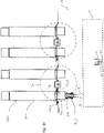
- FIG. 1a shows a logistics security system 1 for securing a logistics area 100, which is a loading zone 102 according to this exemplary embodiment.
- the loading zone 102 here includes four parking spaces for transport vehicles 200a, 200b, 200c, 200d, with the logistics area 100 being approximately at the height of the loading areas 202a, 202b, 202c, 202d of the transport vehicles 200a, 200b, 200c, 200d.
- the loading zone 102 has four loading ramps 106a, 106b, 106c, 106d.
- These loading ramps 106a, 106b, 106c, 106d can be placed on the loading areas 202a, 202b, 202c, 202d and enable a first vehicle 3a, which is a forklift truck 5 here, to drive onto the loading areas 202a, 202b, 202c, 202d.
- a first vehicle 3a which is a forklift truck 5 here
- the first is driving Vehicle 3a onto the loading area 202a of the first transport vehicle 200a and passes through a gate 108a.
- the other parking spaces also have gates 108a, 108b, 108c, 108d.
- the gates 108a, 108b, 108c, 108d are preferably closed when no transport vehicle 200a, 200b, 200c, 200d is being loaded and/or unloaded.
- a first control module 7a of the logistics security system 1 defines a first control zone 9a.
- the first control module 7a is arranged here in a fixed relation between the first gate 108a and the second gate 108b, with the first control zone 7a covering the two gates 108a, 108b or transition areas between the loading ramps 106a, 106b, 106c, 106d and the loading areas 200a, 200b, 200c, 200d covers. It can also be provided that the first control zone 9a only covers the first gate 108a or a transition between the loading ramp 106a and the first loading area 202a.
- a second control module 7b of the logistics security system 1 is arranged between the third gate 108c and the fourth gate 108d and defines a second control zone 9b.
- the first control zone 9a and the second control zone 9b are circular in vertical projection.
- the control zones are square, rectangular, elliptical, trapezoidal, triangular and/or polygonal in a vertical projection.
- a shape of the first control zone 9a can deviate from a shape of the second control zone 9b.
- All control zones 9a, 9b of the logistics security system 1 are preferably of identical design.
- the logistics security system 1 can also have only one control zone 9a, 9b.
- the first control zone 9a could cover all the gates 108a, 108b, 108c, 108d.
- a release module 11 is arranged at a distance from the control modules 7a, 7b and defines a release zone 13.
- the release zone 13 is essentially rectangular here, with these also being circular, elliptical, triangular, square, polygonal or trapezoidal, analogous to the control zones 9a, 9b can. Furthermore, it can also be provided that the release zone 13 touches the first control zone 9a and/or the second control zone 9b or ends directly with them.
- the first control module 7a has a first control antenna unit 15a with a first control antenna 17a.
- the second control unit 7b also has a second control antenna unit 15b with a second control antenna 17b.
- the control antenna units 15a, 15b of the control modules 7a, 7b preferably have a plurality of control antennas 17aa, 17ab, 17ba, 17bb, which are particularly preferably mounted in a fixed spatial relationship to one another.
- the release module 11 also has an antenna unit, which is referred to as a release antenna unit 19 .
- the release antenna unit 19 has two release antennas 21.
- the first control module 7a and the second control module 7b are designed to generate a three-dimensional electromagnetic field (not shown) by means of the control antenna unit 15a, 15b. Furthermore, the control units 7a, 7b are designed to define the control zones 9a, 9b, which are a partial area of the three-dimensional electromagnetic field generated by the respective control unit 7a, 7b. It should be understood that a range of the control antennas 17aa, 17ab, 17ba, 17bb and thus also a size of the electromagnetic fields generated is preferably greater than the area covered by the control zone 9a, 9b.
- the release module 11 is also designed to generate a three-dimensional electromagnetic field by means of the release antennas 21 of the release antenna unit 19, with the release module 11 defining the release zone 13 as a sub-area of this electromagnetic field (not shown) in an analogous manner.
- a first vehicle module 23a is mounted on the vehicle 3a, the structure of which will be explained later.
- the vehicle module 23a is matched to the control antenna unit 15a, 15b and the release antenna unit 19.
- the radio frequency ranges of the vehicle module 23a and the control antenna unit 15a, 15b can be matched to one another. If the first vehicle 3a enters the first control zone 9a, the first vehicle module 23a mounted thereon also enters the control zone 9a.
- both the control module 7a and the first vehicle module 23a are designed to detect whether the first vehicle 3a is in the first control zone 9a.
- the detection of whether the first vehicle 3a is located in the first control zone 9a is carried out only by the first vehicle module 23a or only by the first control module 7a.
- the second control module 7b is also designed here to detect whether the first vehicle module 23a is located in the second control zone 9b.
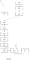
- Steps of a preferred embodiment of the method 2 are explained, which are carried out until it is determined whether the first vehicle 3a is located in the first control zone 9a.
- the first control module 7a In a first step S1, the first control module 7a generates and maintains a three-dimensional electromagnetic field by means of the first control antenna unit 15a.
- a control processing unit 16a figure 7
- the first control zone 9a Defined in a second step S2 a control processing unit 16a ( figure 7 ) of the first control module 7a, the first control zone 9a, which is a partial area of the three-dimensional electromagnetic field generated by the first control antenna unit 15a.
- the first control module 7a then monitors the first control zone 9a (step S3).
- step S4 If the first vehicle module 23a tuned to the control antenna unit 15a enters the first control zone 9a (step S4), this is determined in a fifth step S5 by the first control processing unit 16a of the first control module 7a.
- the control module 7a sends a configuration KK1 of the first control zone 9a to the first vehicle module 23a using the control antenna unit 15a.
- This configuration KK1 of the first control zone 9a receives the first vehicle module 23a by means of a first vehicle antenna unit 27a ( figure 7 ), which in turn is connected to a first vehicle processing unit 25a (step S7).
- the first vehicle processing unit 25a uses the received configuration KK1 of the first control zone 9a to determine that the first vehicle 3a is located within the first control zone 9a (step S8). In a ninth step S9, the first vehicle processing unit 25a sets a safety status indicator IS in the first vehicle processing unit 25a in response to this determination.
- the first vehicle processing unit 25a is connected to a controller 31a (controller 31a is not shown in all figures) of the first vehicle 3a, so that the first vehicle processing unit 25a provides a first restriction signal SB1 to the controller 31a (step S10 ). If the first restriction signal SB1 is provided to the controller 31a, it limits one or more or all degrees of freedom of movement of the first vehicle 3a (step S11).
- the first vehicle module 23a preferably has an output unit 51 ( figure 7 ), which is designed to emit a warning signal if it is determined that the first vehicle 3a is within the control zone 9a.
- a maximum speed of the vehicle 3a is reduced when the restriction signal SB1 is provided.
- a maximum speed of the first vehicle 3a when driving onto the first loading ramp 106a is reduced, thereby preventing damage to the first vehicle 3a.
- collisions of the first vehicle 3a with the first gate 108a and/or a side wall 204a of the first transport vehicle 200a can be avoided.
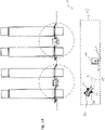
- the first vehicle 3a is arranged on the first loading area 202a of the first transport vehicle 200a and leaves the first control zone 9a in the direction of travel R.
- the vehicle thus moves onto a driver's cab 206a of the first vehicle 3a to.
- the first vehicle processing unit 25a determines that the first vehicle 3a or the first vehicle module 23a is leaving the first control zone 9a. Even if the first vehicle module 23a leaves the control zone 9a, the security status indicator IS is retained in the first vehicle processing unit 25a of the first vehicle module 23a.
- a maximum speed of the first vehicle 3a is also restricted when the vehicle 3a is not located in the first control zone 9a.
- the first control zone 9a can therefore only cover a partial area of the first loading area 202a, which advantageously means that an area to be monitored is limited without reducing the security effect that can be achieved with the logistics security system 1.
- the first vehicle processing unit 25a of the first vehicle module 23a preferably provides a restriction signal SB1 to the controller 31a of the first vehicle 3a such that a maximum lifting height of a lifting mast (not shown) of the forklift truck 5 is restricted. This can prevent a roof (not shown) arranged over the loading area 202a or a tarpaulin (not shown) covering the loading area 202a from being damaged by the lifting mast of the forklift truck 5 . Furthermore, a collision between the lifting mast and the first gate 108a can be avoided.
- the maintenance of the security status indicator IS in the vehicle processing unit 25a when the first vehicle module 23a leaves the first control zone 9a is represented by step S12.
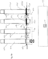
- Figure 1c illustrates that the security status indicator IS is maintained in the first vehicle processing unit 25a of the first vehicle module 23a even if the first vehicle 3a re-enters the first control zone 9a (step S13).
- the first control module 7a is designed to determine whether the first vehicle module 23a enters the first control zone 9a for the second time within a predefined time period T. In response to such a determination that the first vehicle module 23a enters the first control zone 9a for the second time within the predefined time period T (step S13), the first control module 7a triggers a detection device 33 connected to the first control module 7a (step S14 ), which is designed here as a camera 35 (only in Figure 1c shown).
- the camera 35 When the camera 35 is triggered, it takes a picture of the first vehicle 3a and the load (not shown) transported by this first vehicle 3a. The image can then be used to determine whether the charge is damaged when it is unloaded from the loading area 202a onto the loading zone 102 . It can provision can also be made for the first control module 7a to be designed to trigger the detection device 33 when the first vehicle module 23a is located in the first control zone 9a for the first time within a predefined time period T. This is particularly desirable if, after logistics processing, it is to be determined whether the transported goods were already damaged when they were loaded onto a transport vehicle 200a, 200b, 200c, 200d. Considering the predefined period of time is then particularly desirable because the first vehicle 3a typically drives through the first control zone 9a several times a day.
- FIG. 2b illustrates the course of the preferred embodiment of method 2 when the vehicle 3a enters the release zone 11, with the preceding steps S11 to S14 in figure 4 only step S14 is shown.
- the release module 11 generates a three-dimensional electromagnetic field (not shown) by means of the release antenna unit 19.
- a release processing unit 35 of the release module 11 defines the release zone 13 which is a partial area of the three-dimensional electromagnetic field generated by the release antenna unit 19 (step S16). It should be understood that the release zone 13 is preferably smaller than a total range of the release antennas 21.
- the release module 11 monitors the release zone 13 in a seventeenth step S17 of method 2. If the first vehicle 3a, on which the first vehicle module 23a is mounted, now drives into the release zone 13 in an eighteenth step S18, this is done in a nineteenth step S19 determined by the release processing unit 35 of the release module 11. In response to determining that the first vehicle module 23a matched to the release processing unit 19 is in the release zone 13, the release module 11 sends a configuration of the release zone 13 to the first vehicle module 23a (step S20). When the first vehicle module 23a receives the configuration of the release zone 13 (step S21), the first vehicle processing unit 25a of the first vehicle module 23a determines that the first vehicle 3a is in the release zone 13 (step S22).
- the safety status indicator IS is deleted from the first vehicle processing unit 25a in a twenty-third step S23.
- a second status indicator I2 can be set in the first vehicle processing unit 25a in a twenty-fourth step S24 if it is determined that the first vehicle module 23a is within the release zone 13 .
- the security status indicator IS is deleted or replaced by a second status indicator I2
- the first vehicle processing unit 25a provides a release signal SF to the controller 31a of the first vehicle 3a (step S25).
- a restriction on the degree of freedom of movement of the vehicle 3a which here corresponds to a restriction on the maximum speed of the vehicle 3a, is preferably lifted.
- a restriction of the degree of freedom of movement of the first vehicle 3a is only partially lifted and/or that a restriction of a first degree of freedom of movement is lifted while a restriction of a second degree of freedom of movement of the first vehicle 3a is retained.
- a maximum speed of the vehicle 3a can be increased when the second status indicator I2 is set, with a maximum acceleration of the first vehicle 3a remaining limited.
- a further restriction of the at least one degree of freedom of movement of the vehicle 3a preferably takes place when the second status indicator I2 is set in the first vehicle processing unit 25a.
- steps S15 to S17 are preferably carried out in parallel with steps S1 to S14. It should thus be made clear that the release zone 13 and the control zone 9a, 9b are preferably monitored simultaneously.
- a second vehicle 3b and a third vehicle 3c are shown in the logistics area 100 in addition to the first vehicle 3a.
- the arrangement of the control modules 7a, 7b, the release module 11, the control zones 9a, 9b and the release zone 13 is in the figures 3a , 3b analogous to that in the Figures 1a to 1d arrangement shown.
- the second vehicle 3b has a second vehicle module 23b and the third vehicle 3c has a third vehicle module 23c.
- the first vehicle module 23a, the second vehicle module 23b and the third vehicle module 23c are preferably of identical design.
- the first vehicle module 23a has a first vehicle antenna unit 27a, which is designed to generate a three-dimensional electromagnetic field (not shown).
- the first vehicle processing unit 25a is configured to define a first vehicle warning zone 37a, which is a portion of the three-dimensional electromagnetic field generated by the first vehicle antenna unit 27a.
- the first vehicle warning zone 37a is circular in a vertical projection.
- the first vehicle warning zone is square, rectangular, trapezoidal, triangular, elliptical or polygonal. Provision can furthermore be made for the first vehicle warning zone 37a to have a plurality of sub-areas which preferably do not overlap and/or are formed at a distance from one another.
- a first partial area of the first vehicle warning zone 37a can extend in the direction of travel R from the first vehicle 3a
- a second partial area of the first vehicle warning zone 37a can extend counter to the direction of travel R from a rear end 39 of the first vehicle 3a.
- the second partial area is preferably smaller than the first partial area.
- the second vehicle module 23b and the third vehicle module 23c are also designed to generate second and third vehicle warning zones, with the second vehicle warning zone 37b only being shown in part of the figures and the third vehicle warning zone not being shown for reasons of illustration.
- the second vehicle module 23b mounted on the second vehicle 3b enters in Figure 3a straight into the first vehicle warning zone 37.
- FIG 4 illustrates steps of a preferred embodiment of method 2, which are preferably carried out consecutively or in parallel with steps S1 to S25 described above.
- the first vehicle module 23a generates a three-dimensional electromagnetic field by means of the first vehicle antenna unit 27a, with the first vehicle processing unit 25a then defining the first vehicle warning zone 37a.
- the first vehicle warning zone 37a is a partial area of the three-dimensional electromagnetic field generated by the first vehicle antenna unit 27a (step S27).
- the first vehicle processing unit 25a monitors the first vehicle warning zone 37a (step S28).
- step S29 When the second vehicle module 23b matched to the first vehicle antenna unit 27 enters the first vehicle warning zone 37 (step S29), it is detected by the first vehicle processing unit 25a (step S30). In response to the determination, the first vehicle module 23a transmits the configuration KW1 of the first vehicle warning zone 37a to the second vehicle module 23b using the first vehicle antenna unit 27a (step S31).
- the second vehicle module 23b uses a second vehicle processing unit 25b to receive the configuration KW1 of the first vehicle warning zone 37a sent by the first vehicle module 23a (step S32) and determines that the second vehicle module 23b is within the first vehicle warning zone 37a (step S33). If it is determined that the second vehicle module 23b is within the first vehicle warning zone 37a, the second vehicle module 23b sends a status indicator I set in the second vehicle processing unit 25b of the second vehicle module 23b to the first vehicle module 23a (step S S34).
- the first vehicle module 23a uses the first vehicle antenna unit 27a to receive the status indicator I set in the second vehicle processing unit 25b of the second vehicle module 23b (step S35) and, using the first vehicle processing unit 25a, in a thirty-sixth step S36 compares the status indicators I, the are set in the first vehicle processing unit 25a and the second vehicle processing unit 25b.
- the second vehicle module 23b can also define a second vehicle warning zone 37b and preferably executes steps S26 to S36 of method 2 simultaneously with the first vehicle module 23a.
- the first vehicle 3a drives onto the first loading area 202a of the first transport vehicle 200a and thereby crosses the first control zone 9a, so that the security status indicator IS is set in the first vehicle processing unit 25a.
- the second vehicle 3b is located on the loading area 202b of the second transport vehicle 200b and has crossed the first control zone 9a for this purpose.
- the security status indicator IS was also set in the second vehicle processing unit 25b of the second vehicle module 23b.
- the security status indicator IS was retained in the second vehicle processing unit 25b when the second vehicle 3b left the first control zone 9a.
- the safety status indicator IS is therefore set both in the first vehicle processing unit 25a and in the second vehicle processing unit 25b.
- step S36 shows that the status indicator IS set in the first vehicle processing unit 25a matches the status indicator IS set in the second vehicle processing unit 25b, with no follow-up operation F being carried out in this exemplary embodiment if the status indicators I of the first vehicle processing unit 25a and the second vehicle processing unit 25b match.
- the third vehicle module 23c is not arranged within the first vehicle warning zone 7a or the second vehicle warning zone 7a, so that no further steps take place here and the monitoring (step S28) is continued.
- Figure 3b shows one to Figure 3a different arrangement of the first, second and third vehicles 3a, 3b, 3c in the logistics area 100.
- the first vehicle 3a is also arranged on the first loading area 202a of the first transport vehicle 200a.
- the third vehicle 3c is on the second loading area 202b of the second transport vehicle 200b arranged and the second vehicle 3b is now neither in one of the control zones 9a, 9b nor in the clearance zone 13.
- the second vehicle warning zone 37b is in Figure 3b only partially shown and a vehicle warning zone generated by the third vehicle module 23c is not shown.
- no status indicator I is set in the second vehicle processing unit 25b of the second vehicle module 23b.
- the first vehicle module 23a is located in the second vehicle warning zone 37b defined by the second vehicle processing unit 25b of the second vehicle module 23b.
- the second vehicle module 23b is located in the first vehicle warning zone 37a of the first vehicle module 23a.
- the arrows 33 show, which illustrate the travel direction R of the vehicles 3a, 3b, 3c, the first vehicle 3a and the second vehicle 3b move towards one another, with direct visual contact between the first vehicle 3a and the second vehicle 3b through the first Gate 108a is prevented. There is therefore a risk of a collision between the first and the second vehicle 3a, 3b, which the logistics security system 1 can prevent.
- figure 4 illustrates process steps of a preferred embodiment of process 2, which are described in Figure 3b illustrated situation and preferably carried out in parallel to the remaining steps S1 to S36.
- the second vehicle module 23b mounted on the second vehicle 3b enters the first vehicle warning zone 37a (step S29).
- the first vehicle module 23a determines this (step S30) and then sends the configuration KW1 of the first vehicle warning zone 37a (step 31) to the second vehicle module 23b.
- the configuration KW1 of the first vehicle warning zone 37a is received at the second vehicle module 23b (step S32), and the second vehicle module 23b responsively determines that it is within the first vehicle warning zone 37 (step S33).
- the second vehicle module 23b then sends the status indicator I set in the second vehicle processing unit 25b to the first vehicle module 23a (step S34). It should be understood that step S34 can also be the sending of information that includes that no status indicator I is set in the second vehicle processing unit 25b.
- the second vehicle 3b is not on one of the loading areas 202a, 202b, 202c, 202d of the transport vehicles 200a, 200b, 200c, 200d. Since the second vehicle 3b was previously in the clearance zone 13, no status indicator I is stored in the second vehicle processing unit 25b.
- the security status indicator IS set because the first vehicle 3a is in the control zone 9a. The comparison of the status indicators I carried out in step S36 therefore shows that the status indicators I set in the first vehicle processing unit 25a and in the second vehicle processing unit 25b differ.
- the first vehicle processing unit 25a In response to the first vehicle processing unit 25a determining that the status indicators I do not match, the first vehicle processing unit 25a performs a follow-up operation F (step S37). In this exemplary embodiment, the first vehicle processing unit 25a provides a second restriction signal SB2 as a subsequent operation 11 . In a thirty-eighth step S38, the controller 31a of the first vehicle 3a restricts a degree of freedom of movement of the first vehicle 3a, with the first vehicle 3a being braked here until it comes to a standstill. Full deceleration is achieved by the in Figure 3b inserted crossing out of the arrow 33 representing the travel direction R of the first vehicle 3a.
- the follow-up operation is carried out taking into account the status indicator I set in the vehicle processing unit 25a.
- a second restriction signal SB2 can be provided if the safety status indicator SI is set and a third restriction signal SB3 is provided if the second status indicator I2 or no status indicator is set.
- the first vehicle 3a is fully braked by the provision of the second restriction signal SB2 (step S38), while the second vehicle 3b is only restricted in its maximum speed by the provision of the third restriction signal SB3 by the second vehicle processing unit 25b (step S38 ; clarified by shortening of the arrow 33).
- the subsequent operation 11 can preferably also include the outputting of a warning signal by means of the output unit 51a, 51b of the vehicle module 23a, 23b, 23c.
- the vehicle module 23a, 23b, 23c can have optical and/or acoustic output units 51a, 51b, such as signal lights, sirens and/or screens.
- Figure 5a illustrates a logistics security system 1 according to a third exemplary embodiment, the first control zone 9a and the second control zone 9b being rectangular in a vertical projection and essentially on the opposite sides of the transport vehicles 200a, 200b, 200c, 200d of the gates 108a, 108b, 108c, 108d arranged are.
- the control antenna units 15a, 15b each have two control antennas 17aa, 17ab, 17ba, 17bb.
- control antennas 17aa, 17ab, 17ba, 17bb can be used to monitor a rectangular control zone 9a, 9b.
- the principle of triangulation is preferably used.
- the control modules 7a, 7b are preferably designed to be connected to gate controls 39c, 39d. in the in Figure 5a
- the second control module 7b is connected to a third gate control 39c of the third gate 108c and a fourth gate control 39d of a fourth gate 108d.
- the gate controls 39c, 39d provide third and fourth closing signals SS3, SS4. It should be understood that the first control module 7a can also be connected to gate controls 39c, 39d.
- the control modules 7a, 7b are preferably designed to define the control zones 9a, 9b using an open state of a transition 41a, 41b, 41c, 41d to be monitored.
- the third port 108c and the fourth port 108b are according to FIG Figure 5b closed, the first gate control 39c and the second gate control 39d providing opening state signals which correspond here to the closing signals SS3, SS4. Since the third gate 108c and the fourth gate 108d are closed, there is no risk of vehicles 3a, 3b, 3b leaning down from the loading zone 102. Therefore, transitions 41c, 41d to the loading areas 202c, 202d do not have to be monitored, and the second control unit 7b consequently does not define a second control zone 9b. It should be understood that the control modules 7a, 7b according to the further exemplary embodiments can also be connected to gate controls of respectively assigned gates 108a, 108b, 108c, 108d.
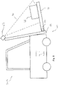
- FIG 6 shows a first vehicle 3a, which is a forklift truck 5 here.
- the first vehicle module 23a has a vehicle detection device 67 which is arranged on a lifting mast 69 of the forklift truck 5 here.
- a detection area 71 of the vehicle detector 67 is directed to loading tines 73 of the forklift 5 so that a load 75 carried by the first vehicle 3a can be detected by the vehicle detector 67 when triggered by the first vehicle processing unit 25a.
- the first vehicle module 23a also has a charge sensor 77 .
- the first vehicle processing unit 25a is connected to the charge sensor 77 and configured to use the charge sensor 77 to determine a charge state of the first To determine vehicle 3a.
- the vehicle processing unit 25a and the charge sensor 77 are connected wirelessly.
- the vehicle processing unit 25a and the charge sensor 77 are connected via infrared, ultrasonic, Bluetoot® and/or radio. Signals, data and/or electrical energy can then be transmitted between the charge sensor 77 and the first vehicle processing unit 25a via infrared, ultrasound, radio or Bluetooth, for example.
- the vehicle detection device 67 and the first vehicle processing unit 25a are preferably also connected wirelessly.
- the first vehicle processing unit 25a may determine whether a state of charge of the vehicle 3a changes using the charge sensor 77 . For example, picking up or putting down the load 75 can be registered by the first vehicle processing unit 25a.
- the first vehicle processing unit 25a is preferably configured to trigger the vehicle detection device 67 in response to a change in the state of charge. For example, when the cargo 75 is parked, the vehicle detection device 67 can capture an image of the cargo 75 at the time of parking. The image can then preferably be used to register damage to the charge 75 . Safety can thus be increased, in particular in the case of dangerous goods.
- the vehicle processing unit 25a can also only be triggered if a predetermined status indicator I, particularly preferably the safety status indicator IS, is set.
- the detection of the charge 75 is often only necessary in areas that are difficult to see or in particularly critical areas, and the processing effort can be effectively reduced by this restriction. For example, it may only be necessary to trigger the vehicle detection device 67 or to take an image of the load 75 if the first vehicle 3a places a dangerous load 75 on the loading area 202a.
- figure 7 shows schematically the structure of a vehicle module 23a, 23b, 23c, a control module 7a, 7b and a release module 11.
- the vehicle module 23a, 23b, 23c has a vehicle antenna unit 27a, 27b, 27c, which is connected here to a first vehicle antenna 41aa and a second vehicle antenna 41ab is shown.
- the vehicle processing unit 25a, 25b, 25c is connected to the vehicle antenna unit 27a, 27b, 27c and also has a vehicle interface 43a, 43b.
- the vehicle interface 43a, 43b is shown here with a first line 45a, 45b and a second line 47a, 47b, with the first line 45a, 45b being designed to receive signals, such as speed signals SV, of the vehicle 3a, 3b, 3c.
- the second line 47a, 47b is for outputting signals from the vehicle module 23a, 23b, 23c to the Vehicle 3a, 3b, 3c provided.
- the restriction signals SB1, SB2, SB3 and the release signal SF can be provided to the controller 31a, 31b of the vehicle 3a, 3b, 3c by means of the second line 47a, 47b.
- the vehicle module 23a, 23b, 23c has a memory 49 in which, for example, configurations for the vehicle warning zone 37a, 37b can be pre-stored. Furthermore, the vehicle module 23a, 23b, 23c has an output unit 51a, 51b, which can output optical and/or acoustic signals, for example, to warn a driver of the vehicle 3a, 3b, 3c.
- the control module 7a, 7b has the control antenna unit 15a, 15b with the control antennas 17aa, 17ab, 17ba, 17bb.
- the control processing unit 16a, 16b is connected to the control antenna unit 15a, 15b and has a control interface 53 for connection to a gate controller 39c, 39d.
- a first line 55 can be used by the control processing unit 16a, 16b to provide signals, such as closing request signals SSA, to the gate controller 39c, 39d.
- the gate control controller 39cC, 39d is preferably designed to close the gate 108c, 108d in response to the provision of a closing request signal SSA.
- a second line 57 of the control interface 53 is designed to receive the closing signals SS3, SS4.
- control module 7a, 7b also has a control memory 59 and a control output unit 61.
- the arrows running between the control unit 15a, 15b and the vehicle module 23a, 23b, 23c represent the sending of the configuration KK of the control zone 9a, 9b and the configuration KW1, KW2 of the vehicle goods zones.
- FIG. 7 shows figure 7 the release module 11 with the release antenna unit 19, the release antennas 21 and a release processing unit 20.
- the release module 11 Analogously to the control module 7a, 7b and the vehicle module 23a, 23b, 23c, the release module 11 also has a release memory 63 and a release Output unit 65 on.
- the arrows running between the release module 11 and the vehicle module 23a, 23b, 23c represent the sending of the configuration KF of the release zone 13 from the release module 11 to the vehicle module 23a, 23b, 23c and a possible sending of the configuration KW1 of the vehicle warning zone 37a, 37b from the Vehicle module 23a, 23b, 23c to the release module 11.
- FIG 8 12 now illustrates the communication of the first vehicle module 23a with the second vehicle module 23b.
- the vehicle modules 23a, 23b are identical here and each have a vehicle antenna unit 27a, 27b, two vehicle antennas 41aa, 41ab, 41ba, 41bb, a vehicle processing unit 25a, 25b, a memory 49a, 49b, a Interface 43a, 43b and an output unit 51a, 51b.
- the first vehicle module 23a is designed to use the first vehicle antenna unit 27a to send a configuration KW1 of the first vehicle warning zone 37a and/or the status indicator I set in the first vehicle processing unit 25a to the second vehicle module 23b.
- the second vehicle module 23b is designed to send a configuration KW2 of the second vehicle warning zone 37b and/or a status indicator I set in the second vehicle processing unit 25b.
Landscapes
- Business, Economics & Management (AREA)
- Engineering & Computer Science (AREA)
- Tourism & Hospitality (AREA)
- Economics (AREA)
- Mechanical Engineering (AREA)
- Theoretical Computer Science (AREA)
- Development Economics (AREA)
- General Physics & Mathematics (AREA)
- Strategic Management (AREA)
- General Business, Economics & Management (AREA)
- Physics & Mathematics (AREA)
- Human Resources & Organizations (AREA)
- Marketing (AREA)
- Primary Health Care (AREA)
- Quality & Reliability (AREA)
- Health & Medical Sciences (AREA)
- Educational Administration (AREA)
- Computer Security & Cryptography (AREA)
- General Health & Medical Sciences (AREA)
- Operations Research (AREA)
- Entrepreneurship & Innovation (AREA)
- Structural Engineering (AREA)
- Geology (AREA)
- Life Sciences & Earth Sciences (AREA)
- Traffic Control Systems (AREA)
- Forklifts And Lifting Vehicles (AREA)
- Vehicle Step Arrangements And Article Storage (AREA)
Applications Claiming Priority (1)
| Application Number | Priority Date | Filing Date | Title |
|---|---|---|---|
| DE102020113010.4A DE102020113010A1 (de) | 2020-05-13 | 2020-05-13 | Verfahren zum Sichern eines Logistikbereichs |
Publications (2)
| Publication Number | Publication Date |
|---|---|
| EP3915909A1 EP3915909A1 (de) | 2021-12-01 |
| EP3915909B1 true EP3915909B1 (de) | 2022-11-23 |
Family
ID=75914465
Family Applications (1)
| Application Number | Title | Priority Date | Filing Date |
|---|---|---|---|
| EP21173668.1A Active EP3915909B1 (de) | 2020-05-13 | 2021-05-12 | Verfahren zum sichern eines logistikbereichs |
Country Status (6)
| Country | Link |
|---|---|
| US (1) | US12165234B2 (pl) |
| EP (1) | EP3915909B1 (pl) |
| AU (1) | AU2021203018A1 (pl) |
| DE (1) | DE102020113010A1 (pl) |
| ES (1) | ES2938891T3 (pl) |
| PL (1) | PL3915909T3 (pl) |
Families Citing this family (2)
| Publication number | Priority date | Publication date | Assignee | Title |
|---|---|---|---|---|
| JP2022086361A (ja) * | 2020-11-30 | 2022-06-09 | 株式会社日立製作所 | 車両制御装置および方法 |
| US20230368119A1 (en) * | 2022-05-13 | 2023-11-16 | United States Postal Service | Systems and methods for using machine vision in distribution facility operations and tracking distribution items |
Family Cites Families (7)
| Publication number | Priority date | Publication date | Assignee | Title |
|---|---|---|---|---|
| DE102010005034B4 (de) | 2010-01-15 | 2023-08-17 | Jungheinrich Aktiengesellschaft | Verfahren zur Bewirtschaftung eines Lagers mit einem Flurförderzeug sowie zur Ausführung des Verfahrens geeignetes Flurförderzeug |
| DE102013003593A1 (de) * | 2013-03-01 | 2013-09-19 | Daimler Ag | Verfahren zum Durchführen eines Löschungsvorgangs in einem beschreibbaren Speicherelement |
| EP3985353B1 (en) | 2015-05-06 | 2025-06-25 | Crown Equipment Corporation | Tag layout for industrial vehicle operation |
| DE102016113312A1 (de) | 2016-07-19 | 2018-01-25 | Comnovo Gmbh | Fahrzeugsicherheitsvorrichtung mit Warnzonen |
| DE102018104992A1 (de) * | 2018-03-05 | 2019-09-05 | Jungheinrich Ag | Verfahren und System zur Kollisionsvermeidung in einem Gefahrenbereich einer Warenlogistikeinrichtung |
| KR102893832B1 (ko) * | 2018-08-01 | 2025-12-03 | 크라운 이큅먼트 코포레이션 | 창고 환경 속도 구역 관리를 위한 시스템 및 방법 |
| DE202018105041U1 (de) | 2018-09-04 | 2019-12-05 | Comnovo Gmbh | Torsicherheitssystem zum Verhindern von Kollisionen zwischen einem Fahrzeug und einem Tor und ein Computerprogramm |
-
2020
- 2020-05-13 DE DE102020113010.4A patent/DE102020113010A1/de not_active Ceased
-
2021
- 2021-05-12 PL PL21173668.1T patent/PL3915909T3/pl unknown
- 2021-05-12 ES ES21173668T patent/ES2938891T3/es active Active
- 2021-05-12 AU AU2021203018A patent/AU2021203018A1/en active Pending
- 2021-05-12 EP EP21173668.1A patent/EP3915909B1/de active Active
- 2021-05-13 US US17/319,443 patent/US12165234B2/en active Active
Also Published As
| Publication number | Publication date |
|---|---|
| US12165234B2 (en) | 2024-12-10 |
| PL3915909T3 (pl) | 2023-05-15 |
| DE102020113010A1 (de) | 2021-11-18 |
| AU2021203018A1 (en) | 2021-12-09 |
| US20210358069A1 (en) | 2021-11-18 |
| ES2938891T3 (es) | 2023-04-17 |
| EP3915909A1 (de) | 2021-12-01 |
Similar Documents
| Publication | Publication Date | Title |
|---|---|---|
| EP2695797B1 (de) | Verfahren zum fahrerlosen Bewegen eines Fahrzeugs auf einer Parkfläche | |
| EP3894349B1 (de) | Container-verladeanlage und verfahren zur betriebsüberwachung darin | |
| EP2848498B1 (de) | Routenzug und zugehöriges Steuerungsverfahren | |
| DE102015213694A1 (de) | Sensorsystem zum Erkennen überstehender oder freiliegender Objekte in der Umgebung eines Fahrzeugs | |
| EP2487129A1 (de) | Wartungsbestimmung für Flurförderzeugsteuersystem nach Häufigkeit der befahrenen Unregelmässigkeiten | |
| EP3915909A1 (de) | Verfahren zum sichern eines logistikbereichs | |
| EP3847333B1 (de) | Torsicherheitssystem zum verhindern von kollisionen zwischen einem fahrzeug und einem tor | |
| EP4269321B1 (de) | Fördereinrichtung für ladungsträger | |
| DE102019105787B4 (de) | Kraftfahrzeug mit einer Hubladebühne sowie Verfahren zur Sicherungsüberwachung einer Hubladebühnenbewegung für ein entsprechendes Kraftfahrzeug | |
| DE102022122567A1 (de) | Verfahren zur automatisierten Überwachung von zu transportierenden Waren | |
| WO2022179758A1 (de) | Verfahren zur kollisionsfreien bewegung eines krans | |
| EP4451085B1 (de) | Beladen und entladen eines laderaums mit einem ladefahrzeug | |
| EP1914665A2 (de) | Verfahren und Vorrichtung zur Identifizierung von mit RFID-Transpondern gekennzeichneten Objekten | |
| DE102020206882A1 (de) | Detektieren von beweglichen Hindernissen | |
| EP4620889B1 (de) | Bereichsüberwachung bei einem intermodal kran | |
| DE102019009383B4 (de) | Kraftfahrzeug mit einer Hubladebühne sowie Verfahren zur Sicherungsüberwachung einer Hubladebühnenbewegung für ein entsprechendes Kraftfahrzeug | |
| DE102019209145A1 (de) | Detektionsvorrichtung und Fahrzeugsensorsystem | |
| DE10005841B4 (de) | Verfahren und Vorrichtung zur Überwachung der Be- und Entladung von Lastkraftwagen an einer Überladebrücke | |
| EP4625284B1 (de) | Sicherheitssystemverbund zur überwachung eines bereichs und ein verfahren zur überwachung eines solchen bereichs | |
| DE102020109839A1 (de) | Verfahren zur Steuerung und Überwachung von Prozessteilnehmern eines intralogistischen Systems und intralogistisches System | |
| DE102025105335B3 (de) | Verfahren zur Absicherung einer Container-Verladeanlage | |
| EP3919429B1 (de) | Automatisiertes flurförderzeug | |
| DE102019213747A1 (de) | Verfahren und System zur autonomen Steuerung eines Fahrzeugs in einem Logistikterminal | |
| WO2004016537A1 (de) | Containerkran | |
| DE202024101369U1 (de) | Bereichsüberwachung bei einem Intermodal Kran |
Legal Events
| Date | Code | Title | Description |
|---|---|---|---|
| PUAI | Public reference made under article 153(3) epc to a published international application that has entered the european phase |
Free format text: ORIGINAL CODE: 0009012 |
|
| STAA | Information on the status of an ep patent application or granted ep patent |
Free format text: STATUS: THE APPLICATION HAS BEEN PUBLISHED |
|
| AK | Designated contracting states |
Kind code of ref document: A1 Designated state(s): AL AT BE BG CH CY CZ DE DK EE ES FI FR GB GR HR HU IE IS IT LI LT LU LV MC MK MT NL NO PL PT RO RS SE SI SK SM TR |
|
| B565 | Issuance of search results under rule 164(2) epc |
Effective date: 20211029 |
|
| STAA | Information on the status of an ep patent application or granted ep patent |
Free format text: STATUS: REQUEST FOR EXAMINATION WAS MADE |
|
| 17P | Request for examination filed |
Effective date: 20220309 |
|
| RBV | Designated contracting states (corrected) |
Designated state(s): AL AT BE BG CH CY CZ DE DK EE ES FI FR GB GR HR HU IE IS IT LI LT LU LV MC MK MT NL NO PL PT RO RS SE SI SK SM TR |
|
| RIC1 | Information provided on ipc code assigned before grant |
Ipc: B66F 17/00 20060101ALI20220428BHEP Ipc: B65G 69/28 20060101AFI20220428BHEP |
|
| GRAP | Despatch of communication of intention to grant a patent |
Free format text: ORIGINAL CODE: EPIDOSNIGR1 |
|
| STAA | Information on the status of an ep patent application or granted ep patent |
Free format text: STATUS: GRANT OF PATENT IS INTENDED |
|
| INTG | Intention to grant announced |
Effective date: 20220607 |
|
| GRAS | Grant fee paid |
Free format text: ORIGINAL CODE: EPIDOSNIGR3 |
|
| GRAA | (expected) grant |
Free format text: ORIGINAL CODE: 0009210 |
|
| STAA | Information on the status of an ep patent application or granted ep patent |
Free format text: STATUS: THE PATENT HAS BEEN GRANTED |
|
| AK | Designated contracting states |
Kind code of ref document: B1 Designated state(s): AL AT BE BG CH CY CZ DE DK EE ES FI FR GB GR HR HU IE IS IT LI LT LU LV MC MK MT NL NO PL PT RO RS SE SI SK SM TR |
|
| REG | Reference to a national code |
Ref country code: GB Ref legal event code: FG4D Free format text: NOT ENGLISH |
|
| REG | Reference to a national code |
Ref country code: CH Ref legal event code: EP |
|
| REG | Reference to a national code |
Ref country code: AT Ref legal event code: REF Ref document number: 1533038 Country of ref document: AT Kind code of ref document: T Effective date: 20221215 Ref country code: DE Ref legal event code: R096 Ref document number: 502021000263 Country of ref document: DE |
|
| REG | Reference to a national code |
Ref country code: IE Ref legal event code: FG4D Free format text: LANGUAGE OF EP DOCUMENT: GERMAN |
|
| REG | Reference to a national code |
Ref country code: NL Ref legal event code: FP |
|
| REG | Reference to a national code |
Ref country code: LT Ref legal event code: MG9D |
|
| REG | Reference to a national code |
Ref country code: ES Ref legal event code: FG2A Ref document number: 2938891 Country of ref document: ES Kind code of ref document: T3 Effective date: 20230417 |
|
| PG25 | Lapsed in a contracting state [announced via postgrant information from national office to epo] |
Ref country code: SE Free format text: LAPSE BECAUSE OF FAILURE TO SUBMIT A TRANSLATION OF THE DESCRIPTION OR TO PAY THE FEE WITHIN THE PRESCRIBED TIME-LIMIT Effective date: 20221123 Ref country code: PT Free format text: LAPSE BECAUSE OF FAILURE TO SUBMIT A TRANSLATION OF THE DESCRIPTION OR TO PAY THE FEE WITHIN THE PRESCRIBED TIME-LIMIT Effective date: 20230323 Ref country code: NO Free format text: LAPSE BECAUSE OF FAILURE TO SUBMIT A TRANSLATION OF THE DESCRIPTION OR TO PAY THE FEE WITHIN THE PRESCRIBED TIME-LIMIT Effective date: 20230223 Ref country code: LT Free format text: LAPSE BECAUSE OF FAILURE TO SUBMIT A TRANSLATION OF THE DESCRIPTION OR TO PAY THE FEE WITHIN THE PRESCRIBED TIME-LIMIT Effective date: 20221123 Ref country code: FI Free format text: LAPSE BECAUSE OF FAILURE TO SUBMIT A TRANSLATION OF THE DESCRIPTION OR TO PAY THE FEE WITHIN THE PRESCRIBED TIME-LIMIT Effective date: 20221123 |
|
| PG25 | Lapsed in a contracting state [announced via postgrant information from national office to epo] |
Ref country code: RS Free format text: LAPSE BECAUSE OF FAILURE TO SUBMIT A TRANSLATION OF THE DESCRIPTION OR TO PAY THE FEE WITHIN THE PRESCRIBED TIME-LIMIT Effective date: 20221123 Ref country code: LV Free format text: LAPSE BECAUSE OF FAILURE TO SUBMIT A TRANSLATION OF THE DESCRIPTION OR TO PAY THE FEE WITHIN THE PRESCRIBED TIME-LIMIT Effective date: 20221123 Ref country code: IS Free format text: LAPSE BECAUSE OF FAILURE TO SUBMIT A TRANSLATION OF THE DESCRIPTION OR TO PAY THE FEE WITHIN THE PRESCRIBED TIME-LIMIT Effective date: 20230323 Ref country code: HR Free format text: LAPSE BECAUSE OF FAILURE TO SUBMIT A TRANSLATION OF THE DESCRIPTION OR TO PAY THE FEE WITHIN THE PRESCRIBED TIME-LIMIT Effective date: 20221123 Ref country code: GR Free format text: LAPSE BECAUSE OF FAILURE TO SUBMIT A TRANSLATION OF THE DESCRIPTION OR TO PAY THE FEE WITHIN THE PRESCRIBED TIME-LIMIT Effective date: 20230224 |
|
| PG25 | Lapsed in a contracting state [announced via postgrant information from national office to epo] |
Ref country code: SM Free format text: LAPSE BECAUSE OF FAILURE TO SUBMIT A TRANSLATION OF THE DESCRIPTION OR TO PAY THE FEE WITHIN THE PRESCRIBED TIME-LIMIT Effective date: 20221123 Ref country code: RO Free format text: LAPSE BECAUSE OF FAILURE TO SUBMIT A TRANSLATION OF THE DESCRIPTION OR TO PAY THE FEE WITHIN THE PRESCRIBED TIME-LIMIT Effective date: 20221123 Ref country code: EE Free format text: LAPSE BECAUSE OF FAILURE TO SUBMIT A TRANSLATION OF THE DESCRIPTION OR TO PAY THE FEE WITHIN THE PRESCRIBED TIME-LIMIT Effective date: 20221123 Ref country code: DK Free format text: LAPSE BECAUSE OF FAILURE TO SUBMIT A TRANSLATION OF THE DESCRIPTION OR TO PAY THE FEE WITHIN THE PRESCRIBED TIME-LIMIT Effective date: 20221123 Ref country code: CZ Free format text: LAPSE BECAUSE OF FAILURE TO SUBMIT A TRANSLATION OF THE DESCRIPTION OR TO PAY THE FEE WITHIN THE PRESCRIBED TIME-LIMIT Effective date: 20221123 |
|
| REG | Reference to a national code |
Ref country code: DE Ref legal event code: R097 Ref document number: 502021000263 Country of ref document: DE |
|
| PG25 | Lapsed in a contracting state [announced via postgrant information from national office to epo] |
Ref country code: SK Free format text: LAPSE BECAUSE OF FAILURE TO SUBMIT A TRANSLATION OF THE DESCRIPTION OR TO PAY THE FEE WITHIN THE PRESCRIBED TIME-LIMIT Effective date: 20221123 Ref country code: AL Free format text: LAPSE BECAUSE OF FAILURE TO SUBMIT A TRANSLATION OF THE DESCRIPTION OR TO PAY THE FEE WITHIN THE PRESCRIBED TIME-LIMIT Effective date: 20221123 |
|
| PLBE | No opposition filed within time limit |
Free format text: ORIGINAL CODE: 0009261 |
|
| STAA | Information on the status of an ep patent application or granted ep patent |
Free format text: STATUS: NO OPPOSITION FILED WITHIN TIME LIMIT |
|
| 26N | No opposition filed |
Effective date: 20230824 |
|
| PG25 | Lapsed in a contracting state [announced via postgrant information from national office to epo] |
Ref country code: SI Free format text: LAPSE BECAUSE OF FAILURE TO SUBMIT A TRANSLATION OF THE DESCRIPTION OR TO PAY THE FEE WITHIN THE PRESCRIBED TIME-LIMIT Effective date: 20221123 |
|
| PG25 | Lapsed in a contracting state [announced via postgrant information from national office to epo] |
Ref country code: MC Free format text: LAPSE BECAUSE OF FAILURE TO SUBMIT A TRANSLATION OF THE DESCRIPTION OR TO PAY THE FEE WITHIN THE PRESCRIBED TIME-LIMIT Effective date: 20221123 |
|
| PG25 | Lapsed in a contracting state [announced via postgrant information from national office to epo] |
Ref country code: MC Free format text: LAPSE BECAUSE OF FAILURE TO SUBMIT A TRANSLATION OF THE DESCRIPTION OR TO PAY THE FEE WITHIN THE PRESCRIBED TIME-LIMIT Effective date: 20221123 Ref country code: LU Free format text: LAPSE BECAUSE OF NON-PAYMENT OF DUE FEES Effective date: 20230512 |
|
| REG | Reference to a national code |
Ref country code: IE Ref legal event code: MM4A |
|
| PG25 | Lapsed in a contracting state [announced via postgrant information from national office to epo] |
Ref country code: IE Free format text: LAPSE BECAUSE OF NON-PAYMENT OF DUE FEES Effective date: 20230512 |
|
| PG25 | Lapsed in a contracting state [announced via postgrant information from national office to epo] |
Ref country code: IE Free format text: LAPSE BECAUSE OF NON-PAYMENT OF DUE FEES Effective date: 20230512 |
|
| PG25 | Lapsed in a contracting state [announced via postgrant information from national office to epo] |
Ref country code: BG Free format text: LAPSE BECAUSE OF FAILURE TO SUBMIT A TRANSLATION OF THE DESCRIPTION OR TO PAY THE FEE WITHIN THE PRESCRIBED TIME-LIMIT Effective date: 20221123 |
|
| PG25 | Lapsed in a contracting state [announced via postgrant information from national office to epo] |
Ref country code: BG Free format text: LAPSE BECAUSE OF FAILURE TO SUBMIT A TRANSLATION OF THE DESCRIPTION OR TO PAY THE FEE WITHIN THE PRESCRIBED TIME-LIMIT Effective date: 20221123 |
|
| REG | Reference to a national code |
Ref country code: CH Ref legal event code: PL |
|
| PG25 | Lapsed in a contracting state [announced via postgrant information from national office to epo] |
Ref country code: CH Free format text: LAPSE BECAUSE OF NON-PAYMENT OF DUE FEES Effective date: 20240531 |
|
| PGFP | Annual fee paid to national office [announced via postgrant information from national office to epo] |
Ref country code: NL Payment date: 20250522 Year of fee payment: 5 |
|
| PGFP | Annual fee paid to national office [announced via postgrant information from national office to epo] |
Ref country code: DE Payment date: 20250606 Year of fee payment: 5 Ref country code: PL Payment date: 20250415 Year of fee payment: 5 |
|
| PGFP | Annual fee paid to national office [announced via postgrant information from national office to epo] |
Ref country code: GB Payment date: 20250522 Year of fee payment: 5 Ref country code: ES Payment date: 20250616 Year of fee payment: 5 |
|
| PGFP | Annual fee paid to national office [announced via postgrant information from national office to epo] |
Ref country code: BE Payment date: 20250520 Year of fee payment: 5 Ref country code: IT Payment date: 20250530 Year of fee payment: 5 |
|
| PGFP | Annual fee paid to national office [announced via postgrant information from national office to epo] |
Ref country code: FR Payment date: 20250523 Year of fee payment: 5 |
|
| PGFP | Annual fee paid to national office [announced via postgrant information from national office to epo] |
Ref country code: AT Payment date: 20250721 Year of fee payment: 5 |
|
| PG25 | Lapsed in a contracting state [announced via postgrant information from national office to epo] |
Ref country code: CY Free format text: LAPSE BECAUSE OF FAILURE TO SUBMIT A TRANSLATION OF THE DESCRIPTION OR TO PAY THE FEE WITHIN THE PRESCRIBED TIME-LIMIT; INVALID AB INITIO Effective date: 20210512 |
|
| PG25 | Lapsed in a contracting state [announced via postgrant information from national office to epo] |
Ref country code: HU Free format text: LAPSE BECAUSE OF FAILURE TO SUBMIT A TRANSLATION OF THE DESCRIPTION OR TO PAY THE FEE WITHIN THE PRESCRIBED TIME-LIMIT; INVALID AB INITIO Effective date: 20210512 |
|
| PG25 | Lapsed in a contracting state [announced via postgrant information from national office to epo] |
Ref country code: TR Free format text: LAPSE BECAUSE OF FAILURE TO SUBMIT A TRANSLATION OF THE DESCRIPTION OR TO PAY THE FEE WITHIN THE PRESCRIBED TIME-LIMIT Effective date: 20221123 |