EP3914474B1 - Führungsvorrichtung mit verriegelungsvorrichtung - Google Patents
Führungsvorrichtung mit verriegelungsvorrichtung Download PDFInfo
- Publication number
- EP3914474B1 EP3914474B1 EP20706618.4A EP20706618A EP3914474B1 EP 3914474 B1 EP3914474 B1 EP 3914474B1 EP 20706618 A EP20706618 A EP 20706618A EP 3914474 B1 EP3914474 B1 EP 3914474B1
- Authority
- EP
- European Patent Office
- Prior art keywords
- guide
- lock
- locking
- control surface
- assigned
- Prior art date
- Legal status (The legal status is an assumption and is not a legal conclusion. Google has not performed a legal analysis and makes no representation as to the accuracy of the status listed.)
- Active
Links
Images


Classifications
-
- B—PERFORMING OPERATIONS; TRANSPORTING
- B60—VEHICLES IN GENERAL
- B60N—SEATS SPECIALLY ADAPTED FOR VEHICLES; VEHICLE PASSENGER ACCOMMODATION NOT OTHERWISE PROVIDED FOR
- B60N2/00—Seats specially adapted for vehicles; Arrangement or mounting of seats in vehicles
- B60N2/005—Arrangement or mounting of seats in vehicles, e.g. dismountable auxiliary seats
- B60N2/015—Attaching seats directly to vehicle chassis
- B60N2/01508—Attaching seats directly to vehicle chassis using quick release attachments
- B60N2/01516—Attaching seats directly to vehicle chassis using quick release attachments with locking mechanisms
- B60N2/01525—Attaching seats directly to vehicle chassis using quick release attachments with locking mechanisms with locking elements expanding inside or under the vehicle floor or rail
- B60N2/01541—Attaching seats directly to vehicle chassis using quick release attachments with locking mechanisms with locking elements expanding inside or under the vehicle floor or rail using moving hooks
-
- B—PERFORMING OPERATIONS; TRANSPORTING
- B60—VEHICLES IN GENERAL
- B60N—SEATS SPECIALLY ADAPTED FOR VEHICLES; VEHICLE PASSENGER ACCOMMODATION NOT OTHERWISE PROVIDED FOR
- B60N2/00—Seats specially adapted for vehicles; Arrangement or mounting of seats in vehicles
- B60N2/02—Seats specially adapted for vehicles; Arrangement or mounting of seats in vehicles the seat or part thereof being movable, e.g. adjustable
- B60N2/04—Seats specially adapted for vehicles; Arrangement or mounting of seats in vehicles the seat or part thereof being movable, e.g. adjustable the whole seat being movable
- B60N2/06—Seats specially adapted for vehicles; Arrangement or mounting of seats in vehicles the seat or part thereof being movable, e.g. adjustable the whole seat being movable slidable
- B60N2/08—Seats specially adapted for vehicles; Arrangement or mounting of seats in vehicles the seat or part thereof being movable, e.g. adjustable the whole seat being movable slidable characterised by the locking device
- B60N2/0812—Location of the latch
- B60N2/0818—Location of the latch inside the rail
-
- B—PERFORMING OPERATIONS; TRANSPORTING
- B60—VEHICLES IN GENERAL
- B60N—SEATS SPECIALLY ADAPTED FOR VEHICLES; VEHICLE PASSENGER ACCOMMODATION NOT OTHERWISE PROVIDED FOR
- B60N2/00—Seats specially adapted for vehicles; Arrangement or mounting of seats in vehicles
- B60N2/02—Seats specially adapted for vehicles; Arrangement or mounting of seats in vehicles the seat or part thereof being movable, e.g. adjustable
- B60N2/04—Seats specially adapted for vehicles; Arrangement or mounting of seats in vehicles the seat or part thereof being movable, e.g. adjustable the whole seat being movable
- B60N2/06—Seats specially adapted for vehicles; Arrangement or mounting of seats in vehicles the seat or part thereof being movable, e.g. adjustable the whole seat being movable slidable
- B60N2/08—Seats specially adapted for vehicles; Arrangement or mounting of seats in vehicles the seat or part thereof being movable, e.g. adjustable the whole seat being movable slidable characterised by the locking device
- B60N2/0831—Movement of the latch
- B60N2/0837—Movement of the latch pivoting
- B60N2/0843—Movement of the latch pivoting about a longitudinal axis
-
- B—PERFORMING OPERATIONS; TRANSPORTING
- B60—VEHICLES IN GENERAL
- B60N—SEATS SPECIALLY ADAPTED FOR VEHICLES; VEHICLE PASSENGER ACCOMMODATION NOT OTHERWISE PROVIDED FOR
- B60N2/00—Seats specially adapted for vehicles; Arrangement or mounting of seats in vehicles
- B60N2/02—Seats specially adapted for vehicles; Arrangement or mounting of seats in vehicles the seat or part thereof being movable, e.g. adjustable
- B60N2/04—Seats specially adapted for vehicles; Arrangement or mounting of seats in vehicles the seat or part thereof being movable, e.g. adjustable the whole seat being movable
- B60N2/06—Seats specially adapted for vehicles; Arrangement or mounting of seats in vehicles the seat or part thereof being movable, e.g. adjustable the whole seat being movable slidable
- B60N2/08—Seats specially adapted for vehicles; Arrangement or mounting of seats in vehicles the seat or part thereof being movable, e.g. adjustable the whole seat being movable slidable characterised by the locking device
- B60N2/0881—Activation of the latches by the control mechanism
-
- B—PERFORMING OPERATIONS; TRANSPORTING
- B60—VEHICLES IN GENERAL
- B60N—SEATS SPECIALLY ADAPTED FOR VEHICLES; VEHICLE PASSENGER ACCOMMODATION NOT OTHERWISE PROVIDED FOR
- B60N2/00—Seats specially adapted for vehicles; Arrangement or mounting of seats in vehicles
- B60N2/02—Seats specially adapted for vehicles; Arrangement or mounting of seats in vehicles the seat or part thereof being movable, e.g. adjustable
- B60N2/04—Seats specially adapted for vehicles; Arrangement or mounting of seats in vehicles the seat or part thereof being movable, e.g. adjustable the whole seat being movable
- B60N2/06—Seats specially adapted for vehicles; Arrangement or mounting of seats in vehicles the seat or part thereof being movable, e.g. adjustable the whole seat being movable slidable
- B60N2/07—Slide construction
- B60N2/075—Slide construction roller-less
Definitions
- Such a guide device is known from prior public use.
- a piece of equipment is movably guided on a guideway fixed to the vehicle and can be locked in different positions relative to the guideway.
- the guiding device comprises a locking device which can be moved between a locking position and a release position by actuating a first or a second of two handles. By operating a third handle, the piece of equipment could be released from the guide track.
- a guide device is for example from FR 2 864 481 A1 disclosed.
- the object of the invention was to provide a guide device which is easier to handle.
- the guiding device comprises first guiding means, which are assigned to an item of equipment and second guiding means, which are assigned to a structure of the vehicle and which form a guide track along which the item of equipment is movably guided in opposite track directions x1, x2.
- the first guide means are formed, for example, by sliding elements and/or rolling elements, which form a bearing with the second guide means in such a way that the piece of equipment is movably guided along the guide track.
- the guideway is e.g. linear.
- the guideway is curved.
- the guideway can, for example, alternatively also have straight and curved sections.
- the guiding device includes a locking device that includes an X-lock and a Z-lock.
- the X-locking device has first locking means assigned to the piece of equipment and second locking means assigned to the vehicle structure, by means of which a movement of the piece of equipment along the path directions x1, x2 can be releasably locked.
- the Z-lock comprises primary locking means assigned to the piece of equipment and secondary locking means assigned to the vehicle structure, by means of which a movement in a third direction (z1) for removal from the guide track can be releasably locked.
- the locking device has at least first actuating means and second actuating means, with which the X-lock and/or the Z-lock can be moved between a locking position and a release position.
- first actuating means and second actuating means with which the X-lock and/or the Z-lock can be moved between a locking position and a release position.
- the Z-lock can be moved into a release position according to the invention.
- first actuating means and the second actuating means can be moved, for example, one after the other from an unactuated position to an actuated position in order to move the Z-lock from a locking position to a release position.
- first actuating means and the second actuating means can be operable at the same time.
- the second guide means comprise, for example, at least one rail, in particular two rails.
- a rail can be used to guide along a straight and/or curved guideway.
- X-locking and Z-locking can be provided with the rail with little additional effort.
- the rail can, for example, have slots arranged transversely to the course of the guide track, which interact with a latch of the piece of equipment, which can be moved into engagement with at least one of the slots or out of engagement with the slots.
- the rail has, for example, a horizontally running web area, which the bolt can reach from behind to prevent movement in the Z-direction.
- the first locking means cooperates with at least one first control surface and the primary locking means cooperates with at least one second control surface, the first control surface and the second control surface being movable between a locking position and a release position.
- the first control and the second control may be associated with one control or different controls that are separately or are movable together.
- One or more first control surfaces and/or second control surfaces can be formed on each control element.
- an end area of a movable bolt can be controlled by the control surface in such a way that it can be moved by the control surface into the bolted position and/or into the release position when the control element with the control surface moves relative to the bolt.
- the first control surface and the second control surface are associated with a control element that is movable between a latched position, a first release position, and a second release position.
- first release position for example, only the X-lock is moved into the release position, so that the piece of equipment can be moved in both web directions.
- second release position for example, the Z-lock and possibly also the X-lock are moved into the release position, so that the piece of equipment can also be removed from the guide rail.
- the first control surface and/or the second control surface is assigned to a connecting link.
- the link has a first guide surface and an opposite second guide surface. For example, if a portion of a bolt is received in the link, the movement of the bolt from the locked position to the release position can be controlled by the first guide surface and the reverse movement from the release position to the locked position by the second guide surface of the link.
- control element is moved by a certain amount L when the first actuating means or the second actuating means is actuated, and the control element is additionally deflected by the same amount L when the other actuating means are then actuated.
- control for example, in the sequentially occurring operation or alternatively to the simultaneous actuation of the first actuation means and the second actuation means, the control element can be displaced by the amount 2L.
- control element can be locked at least in the first release position and/or in the second release position. In this way it can be prevented that, for example, a spring-loaded bolt of the first locking means or the primary locking means automatically moves back into the locking position when the actuating means are returned to the unactuated position.
- the piece of equipment comprises, e.g.
- the second guide means comprise two guide rails and the first guide means comprise at least one sliding element or rolling element cooperating with each guide rail.
- the first locking means and/or the primary locking means comprise, for example, at least one bolt that can be moved between the locking position and the release position.
- the latch can be pivoted, for example, or alternatively mounted so that it can be moved in a translatory manner.
- the locking position the locking bar is in engagement with the second locking means or the secondary locking means.
- the release position the bolt is disengaged from the second locking means or the secondary locking means.
- the guide device as a whole is denoted by the reference numeral 10 in the figures.
- a piece of equipment 11 of a vehicle is shown with the guiding device 10 according to the invention.
- the equipment part is only partially shown.
- Second guide means 12 of the guide device 10 are only represented by a chain line.
- the second guide means 12 interact with the first guide means 14 of the equipment part 11 .
- the first guide means are formed by projections 15 in the present embodiment.
- the projections 15 are held on a base element 17 of the equipment part 11 and protrude in the direction x2 with respect to the base element 17 .
- the projections 15 can be brought into engagement with guide rails 16a and 16b of the second guide means 12 .
- the guide rails 16a and 16b run on a structure 18 of the vehicle, in the present exemplary embodiment on the floor of the vehicle, in a straight line in the direction x1 or x2.
- the piece of equipment 11 is movably guided in the directions x1 and x2 by means of the projections 15 and the guide rails 16a and 16b.
- a portion 23 of the projection 15 acts according to 6 together with the rail 16a in such a way that a movement in direction z2 as well as in the directions y1 and y2 is not possible, but that a movement in the directions x1 and x2 as well as in the direction z1 is possible.
- the guide device 10 comprises locking devices 20a and 20b on both sides 13a and 13b of the base element 17.
- the locking device 20a is described in the figures. Even if the locking device 20b is not described here, it is designed in the same way as the locking device 20a.
- Each of the locking devices 20a and 20b comprises an X-lock 21, with which a movement in the directions x1 and x2 along the guide rails 16a and 16b formed by the second guide means can be locked, and a Z-lock 22, with which a movement in the direction z1 can be locked, so that the piece of equipment 11 cannot be removed from the guide rails 16a and 16b.
- the X-lock 21 and Z-lock 22 of the locking devices 20a and 20b are in the locked position (see the 2 and 5 to 8 ) the piece of equipment 11 cannot be moved in any spatial direction.
- the piece of equipment 11 can be moved in the directions x1 and x2.
- the piece of equipment 11 has an additional degree of freedom in direction z1.
- the piece of equipment 11 can be removed from the guide rails 16a and 16b in the direction z1 and reinserted in the guide rails 16a and 16b in the direction z2.
- the bolt 24a is designed as a two-armed lever - corresponding to the bolt 24b, which is designed in the same way (see 6 ) and comprises a lever arm 25 with a hook-shaped end area 27 and a lever arm 26.
- the end area 27 of the lever arm 25 engages under an overhang 28 of the second guide means 12 extending in the x-direction and thus prevents movement in the z1 direction. A movement in direction x1 and x2 is not prevented by the intervention.
- An end portion 19 of the second lever arm 26 is one with a control surface 52 of a connecting link 29a Control 30a engaged.
- the latch 24a can be moved into engagement with the overhang 28 or out of engagement with the overhang 28 by means of the control element 30a.
- the bolt 24b is in a manner comparable to the bolt 24a in engagement with a connecting link 29b of the control element 30a.
- the bolts 24a and 24b of the locking device 20b are engaged with cams 29a and 29b of a control element 30b and can be engaged or disengaged with the guide rail 16b or the overhang 28 of the secondary locking means be moved.
- a play compensation device 31 is shown on the side 13a of the base element 17 .
- the play compensation device 31 comprises a cylindrical body 32 which is provided with anchor elements 33a and 33b at one end.
- the anchor element 33a interacts with the overhang 28 and the anchor element 33b interacts with an overhang 34 of the second guide means, as a result of which play is compensated for in the Z direction.
- the body 32 is held on the base element 17 about a pivot axis a6 in an upper region.
- Springs, not shown load the anchor elements 33a and 33b in direction z1 against the overhangs 28 and 34 and thereby prevent play in the z-direction.
- Anchor members 33a and 33b can be moved into or out of engagement with overhangs 28 and 34 depending on the position of control members 30a and 30b.
- a bolt 35 of the X-locking device 21 designed as a two-armed lever can be seen.
- the bolt 35 has a lever arm 36, the end region 37 of which is designed in such a way that it engages with at least one slot 38 of a plurality of slots 38 made in the guide rail 16a, which run transversely to the direction x1, x2 of the guide rail 16a is bringable.
- the bolt 35 can be used to prevent the piece of equipment 11 from moving in the directions x1 and x2.
- the end area 37 of the bolt 35 is in engagement with two slots 38.
- An end portion 39 of a lever arm 40 of the bolt 35 engages with a control surface 41 of the control element 30a (the control surface 41 is in 8 not recognizable - see eg figure 5 ).
- the latch 35 is spring loaded such that it automatically moves to the latched position.
- FIG. 5 are the end areas 19 of the two bolts 24a and 24b in an area 51 of a control surface 52 formed by the respective link 29a and 29b.
- the latch 35 In this position of the control 30a, the latch 35 is in the latched position according to FIG figure 5 and 8th emotional.
- the latches 24a and 24b are engaged with the overhang 28.
- the anchor elements 33a and 33b of the lash adjuster 31 engage under the overhangs 28 and 34 (see 7 ).
- the locking device 20a has according to 1 an actuating device 42, by means of which the X-lock 21 can be adjusted separately or together with the Z-lock 22 from a locking position into a release position.
- the actuating device 42 includes a handle 43, which is held pivotable about an axis a4 on the base element 17 and a Handle 44, which is also held on the base element 17 so that it can pivot about an axis a5.
- a transmission device 45 which comprises a lever 46 pivotable about an axis a3 and an actuating rod 47, the control elements 30a and 30b can be displaced by a defined path L in direction x1 when the handle 43 is actuated.
- the handle 44 is connected to a transmission device 48, so that when the handle 44 is actuated, the control elements 30a and 30b are moved by a defined amount L in the direction x1.
- the transmission device 48 comprises links 49 and an actuating rod 50 which interacts with the control elements 30a and 30b.
- the lever 46 pivots about the pivot axis a3 and displaces the actuating rod 47 by the length L in the direction x1.
- the actuating rod 47 is connected to the two control elements 30a and 30b in such a way that they are also moved by a length L in the direction x1.
- the handle 44 is actuated, this also causes the actuating rod 50 to be displaced by a length L in the direction x1 via the link 49 .
- the control elements 30a and 30b are also shifted by the amount L in the direction x1 (see 13 ).
- the end area 39 of the latch 35 is moved relative to the control element 30a or 30b to an area 55 of the respective control element 30a or 30b (see 13 ) in which the control surface 41 is increased with respect to the area 53 by an amount delta Z in the direction z1.
- the end portion 39 of the bolt 35 is therefore also displaced by the amount delta z in the direction z1, the bolt 35 having moved out of engagement with the second locking means, in this case the slot 38, into the release position.
- the control elements 30a and 30b are displaced by the path 2L.
- the end regions 19 are moved into contact with a region 56 of the control surface 52, in which the control surface 52 is raised by delta z in the direction z2 in relation to the region 51.
- the bars 24a and 24b are thereby moved out of engagement with the overhang 28.
- the end area 39 is shifted to the area 57 on the control surface 41 . Its Z position does not change during this movement of the control elements 30a and 30b, i.e. the bolt 35 remains disengaged from the slots 38.
- the piece of equipment 11 can then be removed from the second guide means.
- feeler elements 58 of the locking devices 20a and 20b are moved out of recesses 59 in the base element 17 . If the piece of equipment 11 is reinserted into the second guide means 12, the feeler elements 58 come into contact with the second guide means 12 and move the bolts 24a and 24b into the position according to FIG 13 in which latches 24a and 24b re-engage overhang 28.
- control elements 30a and 30b are shifted to the position according to FIG figure 5 , in which the bolt 35 is also moved back into engagement with the guide rail 16a or 16b.
Landscapes
- Engineering & Computer Science (AREA)
- Aviation & Aerospace Engineering (AREA)
- Transportation (AREA)
- Mechanical Engineering (AREA)
- Lock And Its Accessories (AREA)
- Seats For Vehicles (AREA)
- Bearings For Parts Moving Linearly (AREA)
Description
- Eine solche Führungsvorrichtung ist aus offenkundiger Vorbenutzung bekannt. Ein Ausstattungsteil ist auf einer fahrzeugfesten Führungsbahn bewegbar geführt und kann in unterschiedlichen Positionen relativ zu der Führungsbahn verriegelt werden. Dazu umfasst die Führungsvorrichtung eine Verriegelungsvorrichtung, welche zwischen einer Riegelposition und einer Löseposition bewegt werden kann, indem eine erste oder eine zweite von zwei Handhaben betätigt wird. Durch Betätigen einer dritten Handhabe, konnte das Ausstattungsteil aus der Führungsbahn gelöst werden.
- Eine Führungsvorrichtung nach dem Oberbegriff des Anspruchs 1 ist z.B. aus der
FR 2 864 481 A1 - Es war Aufgabe der Erfindung eine Führungsvorrichtung zu schaffen, die in der Handhabung verbessert ist.
- Die Aufgabe wurde gelöst durch eine Führungsvorrichtung mit den Merkmalen des Anspruchs 1.
- Die Führungsvorrichtung umfasst erste Führungsmittel, die einem Ausstattungsteil zugeordnet sind und zweite Führungsmitteln, die einer Struktur des Fahrzeugs zugeordnet sind und die eine Führungsbahn bilden entlang der das Ausstattungsteil in entgegengesetzte Bahnrichtungen x1, x2 bewegbar geführt ist. Die ersten Führungsmittel sind z.B. von Gleitelementen oder / und Wälzelementen gebildet, die mit den zweiten Führungsmitteln eine Lagerung derart bilden, dass das Ausstattungsteil entlang der Führungsbahn bewegbar geführt ist.
- Die Führungsbahn ist z.B. linear ausgebildet. Alternativ ist die Führungsbahn kurvenförmig ausgebildet. Die Führungsbahn kann z.B. alternativ auch gerade und kurvenförmige Abschnitte aufweisen.
- Die Führungsvorrichtung umfasst eine Verriegelungsvorrichtung, die eine X-Verriegelung und eine Z-Verriegelung einschließt. Die X-Verriegelung weist dem Ausstattungsteil zugeordnete erste Verriegelungsmittel und der Fahrzeugstruktur zugeordnete zweite Verriegelungsmittel auf, mittels welcher eine Bewegung des Ausstattungsteils entlang der Bahnrichtungen x1, x2 lösbar verriegelbar ist.
- Die Z-Verriegelung umfasst dem Ausstattungsteil zugeordnete primäre Verriegelungsmittel und der Fahrzeugstruktur zugeordnete sekundäre Verriegelungsmittel, mittels welcher eine Bewegung in eine dritte Richtung (z1) zur Entnahme aus der Führungsbahn lösbar verriegelbar ist.
- Die Verriegelungsvorrichtung weist wenigstens erste Betätigungsmittel und zweite Betätigungsmittel auf, mit welchen die X-Verriegelung und / oder die Z-Verriegelung zwischen einer Riegelposition und einer Löseposition bewegbar sind. Aufgrund einer Betätigung der ersten Betätigungsmittel oder der zweiten Betätigungsmittel von einer unbetätigten Position in eine betätigte Position ist die X-Verriegelung in eine Löseposition bewegbar.
- Aufgrund der Betätigung der ersten Betätigungsmittel und der zweiten Betätigungsmittel ist erfindungsgemäß die Z-Verriegelung in eine Löseposition bewegbar.
- Dabei können die ersten Betätigungsmittel und die zweiten Betätigungsmittel z.B. nacheinander von einer unbetätigten Position in eine betätigte Position bewegt werden um die Z-Verriegelung von einer Riegelposition in eine Löseposition zu bewegen. Alternativ können die ersten Betätigungsmittel und die zweiten Betätigungsmittel zugleich betätigbar sein. Bei einer Bewegung der Z-Verriegelung in die betätigte Position ist z.B. automatisch die X-Verriegelung in die Löseposition bewegt.
- Auf diese Weise sind die Funktionen X-Verriegelung und Z-Verriegelung entriegelbar ohne hierfür separate Betätigungsmittel vorzusehen.
- Die zweiten Führungsmittel umfassen z.B. wenigstens eine Schiene, insbesondere zwei Schienen. Mit einer Schiene lässt sich die Führung entlang einer geraden und / oder einer gebogenen Führungsbahn realisieren. Darüber hinaus kann mit der Schiene die X-Verriegelung und die Z-Verriegelung mit geringem zusätzlichen Aufwand vorgesehen werden.
- Für die X-Verriegelung kann die Schiene z.B. quer zu dem Verlauf der Führungsbahn angeordnete Schlitze aufweisen, die mit einem Riegel des Ausstattungsteils zusammenwirken, welcher in Eingriff mit wenigstens einem der Schlitze oder außer Eingriff mit den Schlitzen bewegbar ist.
- Für die Z-Verriegelung weist die Schiene z.B. einen horizontal verlaufenden Stegbereich auf, der von dem Riegel hintergriffen werden kann, um eine Bewegung in Z-Richtung zu verhindern.
- Z.B. wirken die ersten Verriegelungsmittel mit wenigstens einer ersten Steuerfläche zusammen und die primären Verriegelungsmittel wirken mit mindestens einer zweiten Steuerfläche zusammen, wobei die erste Steuerfläche und die zweite Steuerfläche zwischen einer Riegelposition und einer Löseposition bewegbar sind. Die erste Steuerfläche und die zweite Steuerfläche können einem Steuerelement oder unterschiedlichen Steuerelementen zugeordnet sein, die separat oder gemeinsam bewegbar sind. An jedem Steuerelement können eine oder mehrere erste Steuerflächen und / oder zweite Steuerflächen ausgebildet sein. Von der Steuerfläche kann z.B. ein Endbereich eines bewegbaren Riegels derart gesteuert werden, dass er von der Steuerfläche in die Riegelposition und / oder in die Löseposition bewegbar ist, wenn sich das Steuerelement mit der Steuerfläche relativ zu dem Riegel bewegt.
- Die erste Steuerfläche und die zweite Steuerfläche sind z.B. einem Steuerelement zugeordnet, welches zwischen einer Riegelposition, einer ersten Löseposition und einer zweiten Löseposition bewegbar ist. In der ersten Löseposition ist z.B. lediglich die X-Verriegelung in die Löseposition bewegt, so dass das Ausstattungsteil in beide Bahnrichtungen bewegbar ist. In der zweiten Löseposition sind z.B. die Z-Verriegelung und ggf. auch die X-Verriegelung in die Löseposition bewegt, so dass das Ausstattungsteil zusätzlich aus der Führungsschiene entnehmbar ist.
- Gemäß einer Ausführungsform ist die erste Steuerfläche und / oder die zweite Steuerfläche einer Kulisse zugeordnet. Die Kulisse weist eine erste Führungsfläche sowie eine gegenüberliegende zweite Führungsfläche auf. Ist z.B. ein Bereich eines Riegels in der Kulisse aufgenommen, so kann die Bewegung des Riegels zwischen der Riegelposition in die Löseposition von der ersten Führungsfläche sowie die umgekehrte Bewegung von der Löseposition in die Riegelposition von der zweiten Führungsfläche der Kulisse gesteuert werden.
- Gemäß einer Ausführungsform wird bei Betätigung der ersten Betätigungsmittel oder der zweiten Betätigungsmittel das Steuerelement um einen bestimmten Betrag L bewegt und bei der anschließenden Betätigung der jeweils anderen Betätigungsmittel wird das Steuerelement um den gleichen Betrag L zusätzlich ausgelenkt. Auf diese Weise kann das Steuerelement z.B. bei der nacheinander erfolgenden Betätigung oder alternativ der gleichzeitigen Betätigung der ersten Betätigungsmittel und der zweiten Betätigungsmittel das Steuerelement um den Betrag 2L verlagert werden.
- Gemäß einer Ausführungsform ist das Steuerelement wenigstens in der ersten Löseposition und / oder in der zweiten Löseposition arretierbar. Auf diese Weise kann verhindert werden, dass z.B. ein federbelasteter Riegel der ersten Verriegelungsmittel oder der primären Verriegelungsmittel sich automatisch in die Riegelposition zurückbewegt, wenn die Betätigungsmittel in die unbetätigte Position zurückgestellt werden.
- Das Ausstattungsteil umfasst z.B. ein Stellelement, bei dessen Betätigung die Arretierung des Steuerelements lösbar ist, wobei das Stellelement derart angeordnet ist, dass beim Einsetzen des Ausstattungsteils in die zweiten Führungsmittel das Stellelement betätigt wird.
- Führungsvorrichtung nach einem der vorangehenden Ansprüche, dadurch gekennzeichnet, dass die zweiten Führungsmittel zwei Führungsschienen und die ersten Führungsmittel wenigstens ein mit jeder Führungsschiene zusammenwirkendes Gleitelement oder Wälzelement umfassen.
- Die ersten Verriegelungsmittel und / oder die primären Verriegelungsmittel umfassen z.B. wenigstens einen zwischen der Riegelposition und der Löseposition bewegbaren Riegel. Der Riegel kann z.B. schwenkbar oder alternativ translatorisch bewegbar gelagert sein. In der Riegelposition steht der Riegel in Eingriff mit den zweiten Verriegelungsmitteln bzw. den sekundären Verriegelungsmitteln. In der Löseposition ist der Riegel außer Eingriff mit den zweiten Verriegelungsmitteln bzw. den sekundären Verriegelungsmitteln.
- Ein Ausführungsbeispiel der Erfindung ist in der nachfolgenden Figurenbeschreibung, auch unter Bezugnahme auf die schematischen Zeichnungen, beispielhaft beschrieben. Dabei werden der Übersichtlichkeit halber - auch soweit unterschiedliche Ausführungsbespiele betroffen sind - gleiche oder vergleichbare Teile oder Elemente oder Bereiche mit gleichen Bezugszeichen, teilweise unter Hinzufügung kleiner Buchstaben, bezeichnet.
- Es zeigen:
-
Fig. 1 eine perspektivische Darstellung eines Ausstattungsteils, wobei die fahrzeugstrukturseitigen Teile der Führungsvorrichtung sowie der Verriegelungsvorrichtung nicht dargestellt sind, -
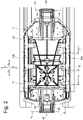
Fig. 2 eine Draufsicht auf das Ausstattungsteil gemäßFig. 1 , -
Fig. 3 eine Draufsicht in Anlehnung anFig. 2 , wobei eine Handhabe betätigt ist, -
Fig. 4 , eine Draufsicht in Anlehnung anFig. 3 , wobei beide Handhaben betätigt sind, -
Fig. 5 eine Schnittdarstellung gemäß Schnittlinie J - J inFig. 2 , -
Fig. 6 eine Schnittdarstellung gemäß Schnittlinie A - A inFig. 2 , -
Fig. 7 eine Schnittdarstellung gemäß Schnittlinie B - B inFig. 2 , -
Fig. 8 eine Schnittdarstellung gemäß Schnittlinie C - C inFig. 2 , -
Fig. 9 eine Schnittdarstellung gemäß Schnittlinie K - K inFig. 3 , -
Fig. 10 eine Schnittdarstellung gemäß Schnittlinie D - D inFig. 3 , -
Fig. 11 eine Schnittdarstellung gemäß Schnittlinie E - E inFig. 3 , -
Fig. 12 eine Schnittdarstellung gemäß Schnittlinie F - F inFig. 3 , -
Fig. 13 eine Schnittdarstellung gemäß Schnittlinie L - L inFig. 4 , -
Fig. 14 eine Schnittdarstellung gemäß Schnittlinie G - G inFig. 4 , -
Fig. 15 eine Schnittdarstellung gemäß Schnittlinie H - H inFig. 4 , -
Fig. 16 eine Schnittdarstellung gemäß Schnittlinie I - I inFig. 4 - Die Führungsvorrichtung insgesamt ist in den Fig. mit dem Bezugszeichen 10 bezeichnet.
- In
Fig. 1 ist ein Ausstattungsteil 11 eines nicht dargestellten Fahrzeugs mit der erfindungsgemäßen Führungsvorrichtung 10 dargestellt. Der Übersichtlichkeit halber ist das Ausstattungsteil nur teilweise dargestellt. Zweite Führungsmittel 12 der Führungsvorrichtung 10 sind lediglich durch eine Strichpunktlinie dargestellt. Die zweiten Führungsmittel 12 wirken mit ersten Führungsmitteln 14 des Ausstattungsteils 11 zusammen. - Die ersten Führungsmittel sind im vorliegenden Ausführungsbeispiel von Vorsprüngen 15 gebildet. Die Vorsprünge 15 sind an einem Bodenelement 17 des Ausstattungsteils 11 gehalten und ragen in Richtung x2 bezüglich des Bodenelements 17 vor. Die Vorsprünge 15 sind mit Führungsschienen 16a und 16b der zweiten Führungsmittel 12 in Eingriff bringbar. Die Führungsschienen 16a und 16b verlaufen an einer Struktur 18 des Fahrzeugs, im vorliegenden Ausführungsbeispiel am Boden des Fahrzeugs, gradlinig in Richtung x1 bzw. x2.
- Mittels der Vorsprünge 15 sowie der Führungsschienen 16a und 16b ist das Ausstattungsteil 11 in die Richtungen x1 und x2 bewegbar geführt. Ein Bereich 23 des Vorsprungs 15 wirkt gemäß
Fig. 6 derart mit der Schiene 16a zusammen, dass eine Bewegung in Richtung z2 sowie in die Richtungen y1 und y2 nicht möglich ist, dass eine Bewegung in die Richtungen x1 und x2 sowie in die Richtung z1 aber möglich ist. - Die Führungsvorrichtung 10 umfasst Verriegelungsvorrichtungen 20a und 20b an beiden Seiten 13a und 13b des Bodenelements 17. In den Fig. ist die Verriegelungsvorrichtung 20a beschrieben. Wenn auch die Verriegelungsvorrichtung 20b hier nicht beschrieben wird, ist sie aber in gleicher Weise wie die Verriegelungsvorrichtung 20a ausgebildet.
- Jede der Verriegelungsvorrichtungen 20a und 20b umfasst eine X-Verriegelung 21, mit welcher eine Bewegung in die Richtungen x1 und x2 entlang der von den zweiten Führungsmitteln gebildeten Führungsschienen 16a und 16b verriegelbar ist sowie eine Z-Verriegelung 22, mit welcher eine Bewegung in Richtung z1 verriegelbar ist, so dass das Ausstattungsteil 11 nicht aus den Führungsschienen 16a und 16b entnehmbar ist. Wenn die X-Verriegelung 21 sowie die Z-Verriegelung 22 der Verriegelungsvorrichtungen 20a und 20b sich in der verriegelten Position befinden (siehe die
Fig. 2 und5 bis 8 ) ist das Ausstattungsteil 11 in keine Raumrichtung bewegbar. - Befindet sich die X-Verriegelung 21 in der Löseposition, kann das Ausstattungsteil 11 in die Richtungen x1 und x2 bewegt werden.
- Wird die Z-Verriegelung 22 in die Löseposition verstellt, hat das Ausstattungsteil 11 einen zusätzlichen Freiheitsgrad in Richtung z1. Das Ausstattungsteil 11 kann aus den Führungsschienen 16a und 16b in Richtung z1 entnommen und in Richtung z2 in die Führungsschienen 16a und 16b wieder eingesetzt werden.
- In
Fig. 1 sind Riegel 24a und 24b der z-Verriegelung 22 der Verriegelungsvorrichtung 20a zu erkennen, die an dem Bodenelement 17 um eine Schwenkachse a1 schwenkbar gelagert sind. Der Riegel 24a ist - entsprechend dem Riegel 24b, der in gleicher Weise gestaltet ist - als zweiarmiger Hebel ausgebildet (sieheFig. 6 ) und umfasst einen Hebelarm 25 mit einem hakenförmigen Endbereich 27 sowie einen Hebelarm 26. Der Endbereich 27 des Hebelarms 25 untergreift einen sich in x-Richtung erstreckenden Überhang 28 der zweiten Führungsmittel 12 und verhindert damit eine Bewegung in Richtung z1. Eine Bewegung in Richtung x1 und x2 wird durch den Eingriff nicht verhindert. Ein Endbereich 19 des zweiten Hebelarms 26 ist mit einer Steuerfläche 52 einer Kulisse 29a eines Steuerelements 30a in Eingriff. Mittels des Steuerelements 30a kann der Riegel 24a in Eingriff mit dem Überhang 28 oder außer Eingriff mit dem Überhang 28 bewegt werden. Der Riegel 24b steht in vergleichbarer Weise wie der Riegel 24a in Eingriff mit einer Kulisse 29b des Steuerelements 30a. - In Gleicher Weise wie die Riegel 24a und 24b der Verriegelungsvorrichtung 20a stehen die Riegel 24a und 24b der Verriegelungsvorrichtung 20b in Eingriff mit Kulissen 29a und 29b eines Steuerelements 30b und können in Eingriff oder außer Eingriff mit der Führungsschiene 16b bzw. dem Überhang 28 der sekundären Verriegelungsmittel bewegt werden.
- In
Fig. 7 ist auf der Seite 13a des Bodenelements 17 eine Spielausgleichvorrichtung 31 dargestellt. Obwohl nicht dargestellt, ist auf der Seite 13b ebenfalls eine Spielausgleichvorrichtung 31 vorhanden, die in gleicher Weise wie die dargestellte ausgebildet ist. Die Spielausgleichvorrichtung 31 umfasst einen zylindrischen Körper 32, welcher an einem Endbereich mit Ankerelementen 33a und 33b versehen ist. Das Ankerelement 33a wirkt mit dem Überhang 28 und das Ankerelement 33b wirkt mit einem Überhang 34 der zweiten Führungsmittel zusammen, wodurch ein Spielausgleich in Z-Richtung erfolgt. - An einem oberen Bereich ist der Körper 32 um eine Schwenkachse a6 an dem Bodenelement 17 gehalten. Nicht dargestellte Federn belasten die Ankerelemente 33a und 33b in Richtung z1 gegen die Überhänge 28 und 34 und verhindern dabei ein Spiel in z-Richtung. Die Ankerelemente 33a und 33b können in Abhängigkeit der Stellung der Steuerelemente 30a und 30b in Eingriff oder außer Eingriff mit den Überhängen 28 und 34 bewegt werden.
- In den
Fig. 1 und8 ist ein als zweiarmiger Hebel ausgebildeter Riegel 35 der X-Verriegelung 21 zu erkennen. Der Riegel 35 weist einen Hebelarm 36 auf, dessen Endbereich 37 derart ausgebildet ist, dass er mit wenigstens einem Schlitz 38 von einer Vielzahl von in die Führungsschiene 16a eingebrachten Schlitzen 38, die quer zu der Erstreckungsrichtung x1, x2 der Führungsschiene 16a verlaufen, in Eingriff bringbar ist. Auf diese Weise kann mit dem Riegel 35 eine Bewegung des Ausstattungsteils 11 in die Richtungen x1 und x2 verhindert werden. GemäßFig. 8 steht der Endbereich 37 des Riegels 35 in Eingriff mit zwei Schlitzen 38. - Ein Endbereich 39 eines Hebelarms 40 des Riegels 35 steht mit einer Steuerfläche 41 des Steuerelements 30a in Eingriff (die Steuerfläche 41 ist in
Fig. 8 nicht erkennbar - siehe z.B.Fig. 5 ). Der Riegel 35 ist derart federbelastet, dass er sich automatisch in die Riegelposition bewegt. - Gemäß
Fig. 5 befinden sich Endbereiche 19 der beiden Riegel 24a und 24b in einem Bereich 51 einer von der jeweiligen Kulisse 29a und 29b gebildeten Steuerfläche 52. Der Endbereich 39 des Riegels 35 ist in einem Bereich 53 der Steuerfläche 41 angeordnet. In dieser Position des Steuerelements 30a ist der Riegel 35 in die Riegelposition gemäß derFig. 5 und8 bewegt. Die Riegel 24a und 24b sind in Eingriff mit dem Überhang 28. Die Ankerelemente 33a und 33b der Spielausgleichvorrichtung 31 untergreifen die Überhänge 28 und 34 (sieheFig. 7 ). - Die Verriegelungsvorrichtung 20a weist gemäß
Fig. 1 eine Betätigungsvorrichtung 42 auf, mittels welcher die X-Verriegelung 21 separat oder gemeinsam mit der Z-Verriegelung 22 aus einer Riegelposition in eine Löseposition verstellbar ist. Die Betätigungsvorrichtung 42 umfasst eine Handhabe 43, welche um eine Achse a4 schwenkbar an dem Bodenelement 17 gehalten ist sowie eine Handhabe 44, die um eine Achse a5 ebenfalls schwenkbar an dem Bodenelement 17 gehalten ist. - Mittels einer Übertragungsvorrichtung 45, welche einen um eine Achse a3 schwenkbaren Hebel 46 sowie eine Betätigungsstange 47 umfasst, können bei Betätigung der Handhabe 43 die Steuerelemente 30a und 30b um einen definierten Weg L in Richtung x1 verlagert werden.
- Die Handhabe 44 steht mit einer Übertragungsvorrichtung 48 in Verbindung, so dass bei Betätigung der Handhabe 44 die Steuerelemente 30a und 30b um einen definierten Betrag L in Richtung x1 bewegt werden. Die Übertragungsvorrichtung 48 umfasst Lenker 49 sowie eine Betätigungsstange 50, welche mit den Steuerelementen 30a und 30b zusammenwirkt.
- Wird nun gemäß
Fig. 1 die Handhabe 43 betätigt, schwenkt der Hebel 46 um die Schwenkachse a3 und verlagert die Betätigungsstange 47 um die Länge L in Richtung x1. Die Betätigungsstange 47 ist derart mit beiden Steuerelementen 30a und 30b verbunden, dass diese ebenfalls um eine Länge L in Richtung x1 bewegt werden. - Wird alternativ die Handhabe 44 betätigt, veranlasst diese über die Lenker 49 die Betätigungsstange 50 ebenfalls um eine Länge L in Richtung x1 zu verlagern. Dabei werden auch die Steuerelemente 30a und 30b um den Betrag L in Richtung x1 verlagert (siehe
Fig. 13 ). - Aufgrund der Verlagerung der Steuerelemente 30a und 30b um den Betrag L in Richtung x1 werden die Endbereiche 19 der Riegel 24a und 24b relativ zu den Kulissen 29a und 29b in den Bereich 54 verlagert. Die Z-Position der Steuerfläche 52 hat sich aber dabei nicht geändert, so dass die Riegel 24a und 24b nicht verschwenkt werden, d.h. sie bleiben in Eingriff mit dem Überhang 28.
- Der Endbereich 39 des Riegels 35 hingegen wird relativ zu dem Steuerelement 30a bzw. 30b auf einen Bereich 55 des jeweiligen Steuerelements 30a bzw. 30b bewegt (siehe
Fig. 13 ), in welchem die Steuerfläche 41 in Bezug auf den Bereich 53 um einen Betrag Delta Z in Richtung z1 erhöht ist. Der Endbereich 39 des Riegels 35 ist daher ebenfalls um den Betrag Delta z in Richtung z1 verlagert wobei sich der Riegel 35 außer Eingriff mit den zweiten Verriegelungsmitteln, in diesem Fall dem Schlitz 38, in die Löseposition bewegt hat. - Wird erst eine der beiden Handhaben 43 oder 44 und dann die andere Handhabe betätigt, so werden die Steuerelemente 30a und 30b um den Weg 2L verlagert. Die Endbereiche 19 werden bei dieser Bewegung in Kontakt mit einem Bereich 56 der Steuerfläche 52 bewegt, in welchem die Steuerfläche 52 in Bezug auf den Bereich 51 um Delta z in Richtung z2 erhöht ist. Dabei werden die Riegel 24a und 24b außer Eingriff mit dem Überhang 28 bewegt. Der Endbereich 39 wird auf der Steuerfläche 41 in den Bereich 57 verlagert. Seine Z-Position verändert sich bei dieser Bewegung der Steuerelemente 30a und 30b nicht, d.h. der Riegel 35 bleibt außer Eingriff mit den Schlitzen 38. Das Ausstattungsteil 11 kann dann aus den zweiten Führungsmitteln entnommen werden.
- Bei dieser Bewegung der Riegel 24a und 24b in die Löseposition werden Tastelemente 58 der Verriegelungsvorrichtungen 20a und 20b aus Aussparungen 59 des Bodenelements 17 herausbewegt. Wird das Ausstattungsteil 11 wieder in die zweiten Führungsmittel 12 eingesetzt, so geraten die Tastelemente 58 in Kontakt mit den zweiten Führungsmitteln 12 und bewegen dabei über die Steuerelemente 30a und 30b die Riegel 24a und 24b in die Position gemäß
Fig. 13 in welcher die Riegel 24a und 24b wieder in Eingriff mit dem Überhang 28 stehen. - Werden die Handhaben 43 und 44 wieder in die Ruhestellung bewegt, folgt eine Verlagerung der Steuerelemente 30a und 30b in die Position gemäß
Fig. 5 , in welcher auch der Riegel 35 wieder in Eingriff mit der Führungsschiene 16a bzw. 16b bewegt ist.
Claims (10)
- Führungsvorrichtung eines Fahrzeugs mit ersten Führungsmitteln (14), die einem Ausstattungsteil (11) zugeordnet sind und mit zweiten Führungsmitteln (12), die einer Struktur (18) des Fahrzeugs zugeordnet sind und die eine Führungsbahn bilden entlang der das Ausstattungsteil (11) in entgegengesetzte Bahnrichtungen (x1, x2) bewegbar geführt ist, mit einer Verriegelungsvorrichtung (20) mit dem Ausstattungsteil (11) zugeordneten ersten Verriegelungsmitteln und mit der Struktur (18) zugeordneten zweiten Verriegelungsmitteln einer X-Verriegelung (21), mittels welcher eine Bewegung entlang der Bahnrichtungen (x1 , x2) lösbar verriegelbar ist und mit dem Ausstattungsteil (11) zugeordneten primären Verriegelungsmitteln und mit der Struktur zugeordneten sekundären Verriegelungsmitteln einer Z-Verriegelung (22) mittels welcher eine Bewegung in eine dritte Richtung (z1) zur Entnahme aus den zweiten Führungsmitteln (12) lösbar verriegelbar ist, wobei die Verriegelungsvorrichtung (20) wenigstens erste Betätigungsmittel (43) und zweite Betätigungsmittel (44) aufweist, mit welchen die X-Verriegelung (21) und / oder die Z-Verriegelung (22) zwischen einer Riegelposition und einer Löseposition bewegbar sind, wobei aufgrund einer Betätigung der ersten Betätigungsmittel (43) oder der zweiten Betätigungsmittel (44) die X-Verriegelung (21 ) in eine Löseposition bewegbar ist, dadurch gekennzeichnet, dass aufgrund der Betätigung der ersten Betätigungsmittel (43) und der zweiten Betätigungsmittel (44) die Z-Verriegelung (22) in eine Löseposition bewegbar ist.
- Führungsvorrichtung nach Anspruch 1, dadurch gekennzeichnet, dass die zweiten Führungsmittel (12) von wenigstens einer Schiene gebildet sind.
- Führungsvorrichtung nach einem der vorangehenden Ansprüche, dadurch gekennzeichnet, dass die ersten Verriegelungsmittel mit wenigstens einer ersten Steuerfläche (41) in Eingriff stehen und dass die primären Verriegelungsmittel mit einer zweiten Steuerfläche (52) in Eingriff sind, wobei die erste Steuerfläche (41) und die zweite Steuerfläche (52) zwischen einer Riegelposition und einer Löseposition bewegbar sind.
- Führungsvorrichtung nach Anspruch 3, dadurch gekennzeichnet, dass die erste Steuerfläche (41) und die zweite Steuerfläche (52) einem Steuerelement (30a, 30b) zugeordnet sind, welches zwischen einer Löseposition, einer ersten Riegelposition und einer zweiten Riegelposition bewegbar ist.
- Führungsvorrichtung nach einem der Ansprüche 3 und 4, dadurch gekennzeichnet, dass die erste Steuerfläche (41) und / oder die zweite Steuerfläche (52) einer Kulisse (29a, 29b) zugeordnet ist.
- Führungsvorrichtung nach einem der Ansprüche 4 und 5, dadurch gekennzeichnet, dass bei Betätigung einer der ersten Betätigungsmittel (43) oder der zweiten Betätigungsmittel (44) das Steuerelement (30a, 30b) um einen bestimmten Betrag (L) ausgelenkt wird und dass bei der anschließenden Betätigung der jeweils anderen Betätigungsmittel das Steuerelement (30a, 30b) um einen bestimmten Betrag (L) zusätzlich ausgelenkt wird.
- Führungsvorrichtung nach einem der Ansprüche 4 bis 6, dadurch gekennzeichnet, dass das Steuerelement (30a, 30b) wenigstens in der Löseposition arretierbar ist.
- Führungsvorrichtung nach Anspruch 7, dadurch gekennzeichnet, dass das Ausstattungsteil (11) ein Stellelement umfasst, bei dessen Betätigung die Arretierung des Steuerelements (30a, 30b) lösbar ist, wobei das Stellelement derart angeordnet ist, dass beim Einsetzen des Ausstattungsteils (11) in die zweiten Führungsmittel (12) das Stellelement betätigt wird.
- Führungsvorrichtung nach einem der vorangehenden Ansprüche, dadurch gekennzeichnet, dass die zweiten Führungsmittel (12) zwei Führungsschienen (16a, 16b) und die ersten Führungsmittel (14) wenigstens ein mit jeder Führungsschiene (16a, 16b) zusammenwirkendes Gleitelement oder Wälzelement umfassen.
- Führungsvorrichtung nach einem der vorangehenden Ansprüche, dadurch gekennzeichnet, dass die ersten Verriegelungsmittel und / oder die primären Verriegelungsmittel von einem schwenkbaren oder einem translatorisch bewegbaren Riegel (24a, 24b) gebildet sind.
Applications Claiming Priority (2)
| Application Number | Priority Date | Filing Date | Title |
|---|---|---|---|
| DE102019000381.0A DE102019000381B4 (de) | 2019-01-22 | 2019-01-22 | Führungsvorrichtung mit Verriegelungsvorrichtung |
| PCT/DE2020/100041 WO2020151787A1 (de) | 2019-01-22 | 2020-01-22 | Führungsvorrichtung mit verriegelungsvorrichtung |
Publications (2)
| Publication Number | Publication Date |
|---|---|
| EP3914474A1 EP3914474A1 (de) | 2021-12-01 |
| EP3914474B1 true EP3914474B1 (de) | 2022-07-27 |
Family
ID=69650507
Family Applications (1)
| Application Number | Title | Priority Date | Filing Date |
|---|---|---|---|
| EP20706618.4A Active EP3914474B1 (de) | 2019-01-22 | 2020-01-22 | Führungsvorrichtung mit verriegelungsvorrichtung |
Country Status (5)
| Country | Link |
|---|---|
| US (1) | US12049158B2 (de) |
| EP (1) | EP3914474B1 (de) |
| CN (1) | CN113474212B (de) |
| DE (1) | DE102019000381B4 (de) |
| WO (1) | WO2020151787A1 (de) |
Families Citing this family (1)
| Publication number | Priority date | Publication date | Assignee | Title |
|---|---|---|---|---|
| DE102019000381B4 (de) * | 2019-01-22 | 2023-04-27 | Volkswagen Aktiengesellschaft | Führungsvorrichtung mit Verriegelungsvorrichtung |
Family Cites Families (15)
| Publication number | Priority date | Publication date | Assignee | Title |
|---|---|---|---|---|
| FR2772686B3 (fr) * | 1997-12-22 | 2000-02-18 | Faure Bertrand Equipements Sa | Ensemble d'assise pour vehicule comportant un siege amovible monte sur glissieres |
| FR2812251B1 (fr) | 2000-07-27 | 2003-01-03 | Antolin Grupo Ing Sa | Dispositif de guidage et d'ancrage pour siege amovible de vehicule |
| FR2864481B1 (fr) | 2003-12-26 | 2006-04-07 | Renault Sas | Agencement pour le montage d'un siege sur le plancher d'un vehicule au moyen de plots de guidage escamotables |
| DE102012017299A1 (de) | 2012-08-31 | 2014-05-15 | Daimler Ag | Verriegelungseinrichtung für eine Sitzanlage eines Fahrzeugs |
| DE102014213166B4 (de) * | 2014-07-07 | 2021-07-29 | Brose Fahrzeugteile SE & Co. Kommanditgesellschaft, Coburg | Fahrzeugsitz mit Rastvorrichtung und zusätzlicher Steuereinrichtung |
| DE102014225426B4 (de) * | 2014-10-20 | 2022-01-13 | Adient Luxembourg Holding S.À R.L. | Längseinsteller für einen Fahrzeugsitz und Fahrzeugsitz |
| US10889208B2 (en) * | 2018-05-04 | 2021-01-12 | Lear Corporation | Track assembly |
| US10906431B2 (en) * | 2018-05-04 | 2021-02-02 | Lear Corporation | Track assembly |
| US10882420B2 (en) * | 2019-03-08 | 2021-01-05 | Lear Corporation | Track assembly |
| US10926667B2 (en) * | 2018-05-04 | 2021-02-23 | Lear Corporation | Track assembly |
| DE102018211055B4 (de) * | 2018-07-04 | 2020-08-06 | Magna Seating (Germany) Gmbh | Arretier- und Kontaktierungssystem zum elektrischen Verbinden eines Bordnetzes eines Kraftfahrzeugs mit einem entnehmbaren Fahrzeugsitz oder einer Sitzanlage |
| EP3628535B1 (de) * | 2018-09-07 | 2021-04-14 | Lazzerini Societa' a Responsabilita' Limitata | Beweglicher rahmen für sitze und entsprechendes gleitsitzsystem |
| US11225201B2 (en) * | 2018-12-10 | 2022-01-18 | Lear Corporation | Track assembly |
| US11440482B2 (en) * | 2018-12-10 | 2022-09-13 | Lear Corporation | Track assembly |
| DE102019000381B4 (de) * | 2019-01-22 | 2023-04-27 | Volkswagen Aktiengesellschaft | Führungsvorrichtung mit Verriegelungsvorrichtung |
-
2019
- 2019-01-22 DE DE102019000381.0A patent/DE102019000381B4/de not_active Expired - Fee Related
-
2020
- 2020-01-22 EP EP20706618.4A patent/EP3914474B1/de active Active
- 2020-01-22 WO PCT/DE2020/100041 patent/WO2020151787A1/de not_active Ceased
- 2020-01-22 CN CN202080009835.7A patent/CN113474212B/zh active Active
-
2021
- 2021-07-21 US US17/381,816 patent/US12049158B2/en active Active
Also Published As
| Publication number | Publication date |
|---|---|
| CN113474212B (zh) | 2023-04-11 |
| DE102019000381B4 (de) | 2023-04-27 |
| EP3914474A1 (de) | 2021-12-01 |
| WO2020151787A1 (de) | 2020-07-30 |
| US20210354597A1 (en) | 2021-11-18 |
| US12049158B2 (en) | 2024-07-30 |
| CN113474212A (zh) | 2021-10-01 |
| DE102019000381A1 (de) | 2020-07-23 |
Similar Documents
| Publication | Publication Date | Title |
|---|---|---|
| EP3209519B1 (de) | Längseinsteller für einen fahrzeugsitz und fahrzeugsitz | |
| DE69401601T2 (de) | Lageeinstellungsvorrichtung für Kraftfahrzeugsitze | |
| DE69800131T2 (de) | Kraftfahrzeugsitzschiene | |
| DE19918622B4 (de) | Gleitschiene für Fahrzeugsitze und Sitz mit einer solchen Gleitschiene | |
| DE102004017491B4 (de) | Schiene für Kraftfahrzeugsitz | |
| DE102013214175A1 (de) | Längseinstellbarer fahrzeugsitz | |
| DE102015219472B4 (de) | Längsverstellvorrichtung für einen Fahrzeugsitz, Schienenpaar und Fahrzeugsitz | |
| DE2729770A1 (de) | Feststellvorrichtung fuer gleitschienenfuehrungen eines fahrzeugsitzes | |
| EP1218217B1 (de) | Längsverstellvorrichtung für kraftfahrzeugsitze | |
| DE102011008172A1 (de) | Armlehne, insbesondere für einen Bürostuhl | |
| EP0094438A1 (de) | Verriegelungsvorrichtung für die Längsverstelleinrichtung eines Fahrzeugsitzes | |
| DE4337938C1 (de) | Fahrzeugsitzreihe, insbesondere Fluggastsitzreihe | |
| DE102014217331B4 (de) | Schienenanordnung für einen Fahrzeugsitz | |
| EP3914474B1 (de) | Führungsvorrichtung mit verriegelungsvorrichtung | |
| DE102021119620A1 (de) | Führungsvorrichtung für eine Haltestange und Kopfstützenvorrichtung mit Führungsvorrichtung | |
| DE4321720C2 (de) | Verriegelungssystem | |
| DE4022391C1 (en) | Frame for perambulator - has foldable frame tubes with latches to hold in selected position | |
| DE102022107268B4 (de) | Verriegelungsvorrichtung für eine Sitzschiene für ein Fahrzeug | |
| DE2653890C2 (de) | Verstelleinrichtung für längsverstellbare Kraftfahrzeugsitze | |
| EP3831650B1 (de) | Ausstattungsvorrichtung | |
| DE102020207924B3 (de) | Verriegelungsvorrichtung für einen Fahrzeugsitz mit einem ein Verriegelungselement in einer Verriegelungsposition formschlüssig sichernden Sicherungsabschnitt, Verriegelungsbaugruppe und Fahrzeugsitz mit einer derartigen Verriegelungsvorrichtung | |
| DE102021130160B4 (de) | Fahrzeugausstattungsteil | |
| DE202021100671U1 (de) | Kopfstütze | |
| DE19720822C1 (de) | Lamellendach für eine Dachöffnung eines Kraftfahrzeuges | |
| EP0800968A2 (de) | Gurthöhenversteller für ein Fahrzeug-Sicherheitsgurtsystem |
Legal Events
| Date | Code | Title | Description |
|---|---|---|---|
| STAA | Information on the status of an ep patent application or granted ep patent |
Free format text: STATUS: UNKNOWN |
|
| STAA | Information on the status of an ep patent application or granted ep patent |
Free format text: STATUS: THE INTERNATIONAL PUBLICATION HAS BEEN MADE |
|
| PUAI | Public reference made under article 153(3) epc to a published international application that has entered the european phase |
Free format text: ORIGINAL CODE: 0009012 |
|
| STAA | Information on the status of an ep patent application or granted ep patent |
Free format text: STATUS: REQUEST FOR EXAMINATION WAS MADE |
|
| 17P | Request for examination filed |
Effective date: 20210818 |
|
| AK | Designated contracting states |
Kind code of ref document: A1 Designated state(s): AL AT BE BG CH CY CZ DE DK EE ES FI FR GB GR HR HU IE IS IT LI LT LU LV MC MK MT NL NO PL PT RO RS SE SI SK SM TR |
|
| GRAP | Despatch of communication of intention to grant a patent |
Free format text: ORIGINAL CODE: EPIDOSNIGR1 |
|
| STAA | Information on the status of an ep patent application or granted ep patent |
Free format text: STATUS: GRANT OF PATENT IS INTENDED |
|
| DAV | Request for validation of the european patent (deleted) | ||
| DAX | Request for extension of the european patent (deleted) | ||
| INTG | Intention to grant announced |
Effective date: 20220421 |
|
| GRAS | Grant fee paid |
Free format text: ORIGINAL CODE: EPIDOSNIGR3 |
|
| GRAA | (expected) grant |
Free format text: ORIGINAL CODE: 0009210 |
|
| STAA | Information on the status of an ep patent application or granted ep patent |
Free format text: STATUS: THE PATENT HAS BEEN GRANTED |
|
| AK | Designated contracting states |
Kind code of ref document: B1 Designated state(s): AL AT BE BG CH CY CZ DE DK EE ES FI FR GB GR HR HU IE IS IT LI LT LU LV MC MK MT NL NO PL PT RO RS SE SI SK SM TR |
|
| REG | Reference to a national code |
Ref country code: CH Ref legal event code: EP |
|
| REG | Reference to a national code |
Ref country code: AT Ref legal event code: REF Ref document number: 1506858 Country of ref document: AT Kind code of ref document: T Effective date: 20220815 |
|
| REG | Reference to a national code |
Ref country code: DE Ref legal event code: R096 Ref document number: 502020001435 Country of ref document: DE |
|
| REG | Reference to a national code |
Ref country code: IE Ref legal event code: FG4D Free format text: LANGUAGE OF EP DOCUMENT: GERMAN |
|
| REG | Reference to a national code |
Ref country code: LT Ref legal event code: MG9D |
|
| REG | Reference to a national code |
Ref country code: NL Ref legal event code: MP Effective date: 20220727 |
|
| PG25 | Lapsed in a contracting state [announced via postgrant information from national office to epo] |
Ref country code: SE Free format text: LAPSE BECAUSE OF FAILURE TO SUBMIT A TRANSLATION OF THE DESCRIPTION OR TO PAY THE FEE WITHIN THE PRESCRIBED TIME-LIMIT Effective date: 20220727 Ref country code: RS Free format text: LAPSE BECAUSE OF FAILURE TO SUBMIT A TRANSLATION OF THE DESCRIPTION OR TO PAY THE FEE WITHIN THE PRESCRIBED TIME-LIMIT Effective date: 20220727 Ref country code: PT Free format text: LAPSE BECAUSE OF FAILURE TO SUBMIT A TRANSLATION OF THE DESCRIPTION OR TO PAY THE FEE WITHIN THE PRESCRIBED TIME-LIMIT Effective date: 20221128 Ref country code: NO Free format text: LAPSE BECAUSE OF FAILURE TO SUBMIT A TRANSLATION OF THE DESCRIPTION OR TO PAY THE FEE WITHIN THE PRESCRIBED TIME-LIMIT Effective date: 20221027 Ref country code: NL Free format text: LAPSE BECAUSE OF FAILURE TO SUBMIT A TRANSLATION OF THE DESCRIPTION OR TO PAY THE FEE WITHIN THE PRESCRIBED TIME-LIMIT Effective date: 20220727 Ref country code: LV Free format text: LAPSE BECAUSE OF FAILURE TO SUBMIT A TRANSLATION OF THE DESCRIPTION OR TO PAY THE FEE WITHIN THE PRESCRIBED TIME-LIMIT Effective date: 20220727 Ref country code: LT Free format text: LAPSE BECAUSE OF FAILURE TO SUBMIT A TRANSLATION OF THE DESCRIPTION OR TO PAY THE FEE WITHIN THE PRESCRIBED TIME-LIMIT Effective date: 20220727 Ref country code: FI Free format text: LAPSE BECAUSE OF FAILURE TO SUBMIT A TRANSLATION OF THE DESCRIPTION OR TO PAY THE FEE WITHIN THE PRESCRIBED TIME-LIMIT Effective date: 20220727 Ref country code: ES Free format text: LAPSE BECAUSE OF FAILURE TO SUBMIT A TRANSLATION OF THE DESCRIPTION OR TO PAY THE FEE WITHIN THE PRESCRIBED TIME-LIMIT Effective date: 20220727 |
|
| PG25 | Lapsed in a contracting state [announced via postgrant information from national office to epo] |
Ref country code: PL Free format text: LAPSE BECAUSE OF FAILURE TO SUBMIT A TRANSLATION OF THE DESCRIPTION OR TO PAY THE FEE WITHIN THE PRESCRIBED TIME-LIMIT Effective date: 20220727 Ref country code: IS Free format text: LAPSE BECAUSE OF FAILURE TO SUBMIT A TRANSLATION OF THE DESCRIPTION OR TO PAY THE FEE WITHIN THE PRESCRIBED TIME-LIMIT Effective date: 20221127 Ref country code: HR Free format text: LAPSE BECAUSE OF FAILURE TO SUBMIT A TRANSLATION OF THE DESCRIPTION OR TO PAY THE FEE WITHIN THE PRESCRIBED TIME-LIMIT Effective date: 20220727 Ref country code: GR Free format text: LAPSE BECAUSE OF FAILURE TO SUBMIT A TRANSLATION OF THE DESCRIPTION OR TO PAY THE FEE WITHIN THE PRESCRIBED TIME-LIMIT Effective date: 20221028 |
|
| PG25 | Lapsed in a contracting state [announced via postgrant information from national office to epo] |
Ref country code: SM Free format text: LAPSE BECAUSE OF FAILURE TO SUBMIT A TRANSLATION OF THE DESCRIPTION OR TO PAY THE FEE WITHIN THE PRESCRIBED TIME-LIMIT Effective date: 20220727 Ref country code: RO Free format text: LAPSE BECAUSE OF FAILURE TO SUBMIT A TRANSLATION OF THE DESCRIPTION OR TO PAY THE FEE WITHIN THE PRESCRIBED TIME-LIMIT Effective date: 20220727 Ref country code: DK Free format text: LAPSE BECAUSE OF FAILURE TO SUBMIT A TRANSLATION OF THE DESCRIPTION OR TO PAY THE FEE WITHIN THE PRESCRIBED TIME-LIMIT Effective date: 20220727 Ref country code: CZ Free format text: LAPSE BECAUSE OF FAILURE TO SUBMIT A TRANSLATION OF THE DESCRIPTION OR TO PAY THE FEE WITHIN THE PRESCRIBED TIME-LIMIT Effective date: 20220727 |
|
| REG | Reference to a national code |
Ref country code: DE Ref legal event code: R097 Ref document number: 502020001435 Country of ref document: DE |
|
| PG25 | Lapsed in a contracting state [announced via postgrant information from national office to epo] |
Ref country code: SK Free format text: LAPSE BECAUSE OF FAILURE TO SUBMIT A TRANSLATION OF THE DESCRIPTION OR TO PAY THE FEE WITHIN THE PRESCRIBED TIME-LIMIT Effective date: 20220727 Ref country code: EE Free format text: LAPSE BECAUSE OF FAILURE TO SUBMIT A TRANSLATION OF THE DESCRIPTION OR TO PAY THE FEE WITHIN THE PRESCRIBED TIME-LIMIT Effective date: 20220727 |
|
| PLBE | No opposition filed within time limit |
Free format text: ORIGINAL CODE: 0009261 |
|
| STAA | Information on the status of an ep patent application or granted ep patent |
Free format text: STATUS: NO OPPOSITION FILED WITHIN TIME LIMIT |
|
| PG25 | Lapsed in a contracting state [announced via postgrant information from national office to epo] |
Ref country code: AL Free format text: LAPSE BECAUSE OF FAILURE TO SUBMIT A TRANSLATION OF THE DESCRIPTION OR TO PAY THE FEE WITHIN THE PRESCRIBED TIME-LIMIT Effective date: 20220727 |
|
| 26N | No opposition filed |
Effective date: 20230502 |
|
| REG | Reference to a national code |
Ref country code: CH Ref legal event code: PL |
|
| PG25 | Lapsed in a contracting state [announced via postgrant information from national office to epo] |
Ref country code: LU Free format text: LAPSE BECAUSE OF NON-PAYMENT OF DUE FEES Effective date: 20230122 |
|
| REG | Reference to a national code |
Ref country code: BE Ref legal event code: MM Effective date: 20230131 |
|
| PG25 | Lapsed in a contracting state [announced via postgrant information from national office to epo] |
Ref country code: LI Free format text: LAPSE BECAUSE OF NON-PAYMENT OF DUE FEES Effective date: 20230131 Ref country code: CH Free format text: LAPSE BECAUSE OF NON-PAYMENT OF DUE FEES Effective date: 20230131 |
|
| PG25 | Lapsed in a contracting state [announced via postgrant information from national office to epo] |
Ref country code: BE Free format text: LAPSE BECAUSE OF NON-PAYMENT OF DUE FEES Effective date: 20230131 |
|
| PG25 | Lapsed in a contracting state [announced via postgrant information from national office to epo] |
Ref country code: IE Free format text: LAPSE BECAUSE OF NON-PAYMENT OF DUE FEES Effective date: 20230122 |
|
| PG25 | Lapsed in a contracting state [announced via postgrant information from national office to epo] |
Ref country code: IT Free format text: LAPSE BECAUSE OF FAILURE TO SUBMIT A TRANSLATION OF THE DESCRIPTION OR TO PAY THE FEE WITHIN THE PRESCRIBED TIME-LIMIT Effective date: 20220727 |
|
| PG25 | Lapsed in a contracting state [announced via postgrant information from national office to epo] |
Ref country code: MC Free format text: LAPSE BECAUSE OF FAILURE TO SUBMIT A TRANSLATION OF THE DESCRIPTION OR TO PAY THE FEE WITHIN THE PRESCRIBED TIME-LIMIT Effective date: 20220727 |
|
| PG25 | Lapsed in a contracting state [announced via postgrant information from national office to epo] |
Ref country code: MC Free format text: LAPSE BECAUSE OF FAILURE TO SUBMIT A TRANSLATION OF THE DESCRIPTION OR TO PAY THE FEE WITHIN THE PRESCRIBED TIME-LIMIT Effective date: 20220727 |
|
| PG25 | Lapsed in a contracting state [announced via postgrant information from national office to epo] |
Ref country code: BG Free format text: LAPSE BECAUSE OF FAILURE TO SUBMIT A TRANSLATION OF THE DESCRIPTION OR TO PAY THE FEE WITHIN THE PRESCRIBED TIME-LIMIT Effective date: 20220727 |
|
| P01 | Opt-out of the competence of the unified patent court (upc) registered |
Free format text: CASE NUMBER: UPC_APP_325664/2023 Effective date: 20230523 |
|
| PG25 | Lapsed in a contracting state [announced via postgrant information from national office to epo] |
Ref country code: BG Free format text: LAPSE BECAUSE OF FAILURE TO SUBMIT A TRANSLATION OF THE DESCRIPTION OR TO PAY THE FEE WITHIN THE PRESCRIBED TIME-LIMIT Effective date: 20220727 |
|
| PGFP | Annual fee paid to national office [announced via postgrant information from national office to epo] |
Ref country code: AT Payment date: 20250417 Year of fee payment: 5 |
|
| PG25 | Lapsed in a contracting state [announced via postgrant information from national office to epo] |
Ref country code: CY Free format text: LAPSE BECAUSE OF FAILURE TO SUBMIT A TRANSLATION OF THE DESCRIPTION OR TO PAY THE FEE WITHIN THE PRESCRIBED TIME-LIMIT; INVALID AB INITIO Effective date: 20200122 |
|
| PG25 | Lapsed in a contracting state [announced via postgrant information from national office to epo] |
Ref country code: HU Free format text: LAPSE BECAUSE OF FAILURE TO SUBMIT A TRANSLATION OF THE DESCRIPTION OR TO PAY THE FEE WITHIN THE PRESCRIBED TIME-LIMIT; INVALID AB INITIO Effective date: 20200122 |
|
| PG25 | Lapsed in a contracting state [announced via postgrant information from national office to epo] |
Ref country code: TR Free format text: LAPSE BECAUSE OF FAILURE TO SUBMIT A TRANSLATION OF THE DESCRIPTION OR TO PAY THE FEE WITHIN THE PRESCRIBED TIME-LIMIT Effective date: 20220727 |
|
| PG25 | Lapsed in a contracting state [announced via postgrant information from national office to epo] |
Ref country code: SI Free format text: LAPSE BECAUSE OF FAILURE TO SUBMIT A TRANSLATION OF THE DESCRIPTION OR TO PAY THE FEE WITHIN THE PRESCRIBED TIME-LIMIT Effective date: 20220727 |
|
| REG | Reference to a national code |
Ref country code: AT Ref legal event code: MM01 Ref document number: 1506858 Country of ref document: AT Kind code of ref document: T Effective date: 20250122 |
|
| PGFP | Annual fee paid to national office [announced via postgrant information from national office to epo] |
Ref country code: GB Payment date: 20260126 Year of fee payment: 7 |
|
| PGFP | Annual fee paid to national office [announced via postgrant information from national office to epo] |
Ref country code: DE Payment date: 20260131 Year of fee payment: 7 |
|
| PG25 | Lapsed in a contracting state [announced via postgrant information from national office to epo] |
Ref country code: AT Free format text: LAPSE BECAUSE OF NON-PAYMENT OF DUE FEES Effective date: 20250122 |
|
| PGFP | Annual fee paid to national office [announced via postgrant information from national office to epo] |
Ref country code: FR Payment date: 20260126 Year of fee payment: 7 |