EP3913636A1 - Verfahren und systeme zur bereitstellung von schnittstellenkomponenten für die atemtherapie - Google Patents
Verfahren und systeme zur bereitstellung von schnittstellenkomponenten für die atemtherapie Download PDFInfo
- Publication number
- EP3913636A1 EP3913636A1 EP21164373.9A EP21164373A EP3913636A1 EP 3913636 A1 EP3913636 A1 EP 3913636A1 EP 21164373 A EP21164373 A EP 21164373A EP 3913636 A1 EP3913636 A1 EP 3913636A1
- Authority
- EP
- European Patent Office
- Prior art keywords
- user
- data
- video
- face
- video frames
- Prior art date
- Legal status (The legal status is an assumption and is not a legal conclusion. Google has not performed a legal analysis and makes no representation as to the accuracy of the status listed.)
- Granted
Links
Images











Classifications
-
- G—PHYSICS
- G16—INFORMATION AND COMMUNICATION TECHNOLOGY [ICT] SPECIALLY ADAPTED FOR SPECIFIC APPLICATION FIELDS
- G16H—HEALTHCARE INFORMATICS, i.e. INFORMATION AND COMMUNICATION TECHNOLOGY [ICT] SPECIALLY ADAPTED FOR THE HANDLING OR PROCESSING OF MEDICAL OR HEALTHCARE DATA
- G16H40/00—ICT specially adapted for the management or administration of healthcare resources or facilities; ICT specially adapted for the management or operation of medical equipment or devices
- G16H40/60—ICT specially adapted for the management or administration of healthcare resources or facilities; ICT specially adapted for the management or operation of medical equipment or devices for the operation of medical equipment or devices
-
- A—HUMAN NECESSITIES
- A61—MEDICAL OR VETERINARY SCIENCE; HYGIENE
- A61B—DIAGNOSIS; SURGERY; IDENTIFICATION
- A61B5/00—Measuring for diagnostic purposes; Identification of persons
- A61B5/0059—Measuring for diagnostic purposes; Identification of persons using light, e.g. diagnosis by transillumination, diascopy, fluorescence
- A61B5/0062—Arrangements for scanning
- A61B5/0064—Body surface scanning
-
- A—HUMAN NECESSITIES
- A61—MEDICAL OR VETERINARY SCIENCE; HYGIENE
- A61B—DIAGNOSIS; SURGERY; IDENTIFICATION
- A61B5/00—Measuring for diagnostic purposes; Identification of persons
- A61B5/103—Measuring devices for testing the shape, pattern, colour, size or movement of the body or parts thereof, for diagnostic purposes
- A61B5/107—Measuring physical dimensions, e.g. size of the entire body or parts thereof
- A61B5/1072—Measuring physical dimensions, e.g. size of the entire body or parts thereof measuring distances on the body, e.g. measuring length, height or thickness
-
- A—HUMAN NECESSITIES
- A61—MEDICAL OR VETERINARY SCIENCE; HYGIENE
- A61B—DIAGNOSIS; SURGERY; IDENTIFICATION
- A61B5/00—Measuring for diagnostic purposes; Identification of persons
- A61B5/103—Measuring devices for testing the shape, pattern, colour, size or movement of the body or parts thereof, for diagnostic purposes
- A61B5/107—Measuring physical dimensions, e.g. size of the entire body or parts thereof
- A61B5/1079—Measuring physical dimensions, e.g. size of the entire body or parts thereof using optical or photographic means
-
- A—HUMAN NECESSITIES
- A61—MEDICAL OR VETERINARY SCIENCE; HYGIENE
- A61M—DEVICES FOR INTRODUCING MEDIA INTO, OR ONTO, THE BODY; DEVICES FOR TRANSDUCING BODY MEDIA OR FOR TAKING MEDIA FROM THE BODY; DEVICES FOR PRODUCING OR ENDING SLEEP OR STUPOR
- A61M16/00—Devices for influencing the respiratory system of patients by gas treatment, e.g. ventilators; Tracheal tubes
- A61M16/021—Devices for influencing the respiratory system of patients by gas treatment, e.g. ventilators; Tracheal tubes operated by electrical means
-
- A—HUMAN NECESSITIES
- A61—MEDICAL OR VETERINARY SCIENCE; HYGIENE
- A61M—DEVICES FOR INTRODUCING MEDIA INTO, OR ONTO, THE BODY; DEVICES FOR TRANSDUCING BODY MEDIA OR FOR TAKING MEDIA FROM THE BODY; DEVICES FOR PRODUCING OR ENDING SLEEP OR STUPOR
- A61M16/00—Devices for influencing the respiratory system of patients by gas treatment, e.g. ventilators; Tracheal tubes
- A61M16/06—Respiratory or anaesthetic masks
-
- A—HUMAN NECESSITIES
- A61—MEDICAL OR VETERINARY SCIENCE; HYGIENE
- A61M—DEVICES FOR INTRODUCING MEDIA INTO, OR ONTO, THE BODY; DEVICES FOR TRANSDUCING BODY MEDIA OR FOR TAKING MEDIA FROM THE BODY; DEVICES FOR PRODUCING OR ENDING SLEEP OR STUPOR
- A61M16/00—Devices for influencing the respiratory system of patients by gas treatment, e.g. ventilators; Tracheal tubes
- A61M16/06—Respiratory or anaesthetic masks
- A61M16/0605—Means for improving the adaptation of the mask to the patient
-
- A—HUMAN NECESSITIES
- A61—MEDICAL OR VETERINARY SCIENCE; HYGIENE
- A61M—DEVICES FOR INTRODUCING MEDIA INTO, OR ONTO, THE BODY; DEVICES FOR TRANSDUCING BODY MEDIA OR FOR TAKING MEDIA FROM THE BODY; DEVICES FOR PRODUCING OR ENDING SLEEP OR STUPOR
- A61M16/00—Devices for influencing the respiratory system of patients by gas treatment, e.g. ventilators; Tracheal tubes
- A61M16/06—Respiratory or anaesthetic masks
- A61M16/0605—Means for improving the adaptation of the mask to the patient
- A61M16/0633—Means for improving the adaptation of the mask to the patient with forehead support
-
- A—HUMAN NECESSITIES
- A61—MEDICAL OR VETERINARY SCIENCE; HYGIENE
- A61M—DEVICES FOR INTRODUCING MEDIA INTO, OR ONTO, THE BODY; DEVICES FOR TRANSDUCING BODY MEDIA OR FOR TAKING MEDIA FROM THE BODY; DEVICES FOR PRODUCING OR ENDING SLEEP OR STUPOR
- A61M16/00—Devices for influencing the respiratory system of patients by gas treatment, e.g. ventilators; Tracheal tubes
- A61M16/06—Respiratory or anaesthetic masks
- A61M16/0683—Holding devices therefor
-
- A—HUMAN NECESSITIES
- A61—MEDICAL OR VETERINARY SCIENCE; HYGIENE
- A61M—DEVICES FOR INTRODUCING MEDIA INTO, OR ONTO, THE BODY; DEVICES FOR TRANSDUCING BODY MEDIA OR FOR TAKING MEDIA FROM THE BODY; DEVICES FOR PRODUCING OR ENDING SLEEP OR STUPOR
- A61M16/00—Devices for influencing the respiratory system of patients by gas treatment, e.g. ventilators; Tracheal tubes
- A61M16/08—Bellows; Connecting tubes ; Water traps; Patient circuits
- A61M16/0816—Joints or connectors
-
- G—PHYSICS
- G06—COMPUTING OR CALCULATING; COUNTING
- G06N—COMPUTING ARRANGEMENTS BASED ON SPECIFIC COMPUTATIONAL MODELS
- G06N20/00—Machine learning
-
- G—PHYSICS
- G06—COMPUTING OR CALCULATING; COUNTING
- G06N—COMPUTING ARRANGEMENTS BASED ON SPECIFIC COMPUTATIONAL MODELS
- G06N20/00—Machine learning
- G06N20/10—Machine learning using kernel methods, e.g. support vector machines [SVM]
-
- G—PHYSICS
- G06—COMPUTING OR CALCULATING; COUNTING
- G06T—IMAGE DATA PROCESSING OR GENERATION, IN GENERAL
- G06T15/00—Three-dimensional [3D] image rendering
- G06T15/10—Geometric effects
- G06T15/20—Perspective computation
- G06T15/205—Image-based rendering
-
- G—PHYSICS
- G06—COMPUTING OR CALCULATING; COUNTING
- G06V—IMAGE OR VIDEO RECOGNITION OR UNDERSTANDING
- G06V10/00—Arrangements for image or video recognition or understanding
- G06V10/20—Image preprocessing
- G06V10/32—Normalisation of the pattern dimensions
-
- G—PHYSICS
- G06—COMPUTING OR CALCULATING; COUNTING
- G06V—IMAGE OR VIDEO RECOGNITION OR UNDERSTANDING
- G06V40/00—Recognition of biometric, human-related or animal-related patterns in image or video data
- G06V40/10—Human or animal bodies, e.g. vehicle occupants or pedestrians; Body parts, e.g. hands
- G06V40/16—Human faces, e.g. facial parts, sketches or expressions
- G06V40/161—Detection; Localisation; Normalisation
- G06V40/165—Detection; Localisation; Normalisation using facial parts and geometric relationships
-
- G—PHYSICS
- G06—COMPUTING OR CALCULATING; COUNTING
- G06V—IMAGE OR VIDEO RECOGNITION OR UNDERSTANDING
- G06V40/00—Recognition of biometric, human-related or animal-related patterns in image or video data
- G06V40/10—Human or animal bodies, e.g. vehicle occupants or pedestrians; Body parts, e.g. hands
- G06V40/16—Human faces, e.g. facial parts, sketches or expressions
- G06V40/161—Detection; Localisation; Normalisation
- G06V40/166—Detection; Localisation; Normalisation using acquisition arrangements
-
- G—PHYSICS
- G06—COMPUTING OR CALCULATING; COUNTING
- G06V—IMAGE OR VIDEO RECOGNITION OR UNDERSTANDING
- G06V40/00—Recognition of biometric, human-related or animal-related patterns in image or video data
- G06V40/10—Human or animal bodies, e.g. vehicle occupants or pedestrians; Body parts, e.g. hands
- G06V40/16—Human faces, e.g. facial parts, sketches or expressions
- G06V40/168—Feature extraction; Face representation
- G06V40/169—Holistic features and representations, i.e. based on the facial image taken as a whole
-
- G—PHYSICS
- G06—COMPUTING OR CALCULATING; COUNTING
- G06V—IMAGE OR VIDEO RECOGNITION OR UNDERSTANDING
- G06V40/00—Recognition of biometric, human-related or animal-related patterns in image or video data
- G06V40/10—Human or animal bodies, e.g. vehicle occupants or pedestrians; Body parts, e.g. hands
- G06V40/16—Human faces, e.g. facial parts, sketches or expressions
- G06V40/168—Feature extraction; Face representation
- G06V40/171—Local features and components; Facial parts ; Occluding parts, e.g. glasses; Geometrical relationships
-
- G—PHYSICS
- G16—INFORMATION AND COMMUNICATION TECHNOLOGY [ICT] SPECIALLY ADAPTED FOR SPECIFIC APPLICATION FIELDS
- G16H—HEALTHCARE INFORMATICS, i.e. INFORMATION AND COMMUNICATION TECHNOLOGY [ICT] SPECIALLY ADAPTED FOR THE HANDLING OR PROCESSING OF MEDICAL OR HEALTHCARE DATA
- G16H20/00—ICT specially adapted for therapies or health-improving plans, e.g. for handling prescriptions, for steering therapy or for monitoring patient compliance
- G16H20/40—ICT specially adapted for therapies or health-improving plans, e.g. for handling prescriptions, for steering therapy or for monitoring patient compliance relating to mechanical, radiation or invasive therapies, e.g. surgery, laser therapy, dialysis or acupuncture
-
- G—PHYSICS
- G16—INFORMATION AND COMMUNICATION TECHNOLOGY [ICT] SPECIALLY ADAPTED FOR SPECIFIC APPLICATION FIELDS
- G16H—HEALTHCARE INFORMATICS, i.e. INFORMATION AND COMMUNICATION TECHNOLOGY [ICT] SPECIALLY ADAPTED FOR THE HANDLING OR PROCESSING OF MEDICAL OR HEALTHCARE DATA
- G16H30/00—ICT specially adapted for the handling or processing of medical images
- G16H30/40—ICT specially adapted for the handling or processing of medical images for processing medical images, e.g. editing
-
- G—PHYSICS
- G16—INFORMATION AND COMMUNICATION TECHNOLOGY [ICT] SPECIALLY ADAPTED FOR SPECIFIC APPLICATION FIELDS
- G16H—HEALTHCARE INFORMATICS, i.e. INFORMATION AND COMMUNICATION TECHNOLOGY [ICT] SPECIALLY ADAPTED FOR THE HANDLING OR PROCESSING OF MEDICAL OR HEALTHCARE DATA
- G16H50/00—ICT specially adapted for medical diagnosis, medical simulation or medical data mining; ICT specially adapted for detecting, monitoring or modelling epidemics or pandemics
- G16H50/50—ICT specially adapted for medical diagnosis, medical simulation or medical data mining; ICT specially adapted for detecting, monitoring or modelling epidemics or pandemics for simulation or modelling of medical disorders
-
- A—HUMAN NECESSITIES
- A61—MEDICAL OR VETERINARY SCIENCE; HYGIENE
- A61B—DIAGNOSIS; SURGERY; IDENTIFICATION
- A61B5/00—Measuring for diagnostic purposes; Identification of persons
- A61B5/08—Measuring devices for evaluating the respiratory organs
-
- A—HUMAN NECESSITIES
- A61—MEDICAL OR VETERINARY SCIENCE; HYGIENE
- A61M—DEVICES FOR INTRODUCING MEDIA INTO, OR ONTO, THE BODY; DEVICES FOR TRANSDUCING BODY MEDIA OR FOR TAKING MEDIA FROM THE BODY; DEVICES FOR PRODUCING OR ENDING SLEEP OR STUPOR
- A61M16/00—Devices for influencing the respiratory system of patients by gas treatment, e.g. ventilators; Tracheal tubes
- A61M16/06—Respiratory or anaesthetic masks
- A61M2016/0661—Respiratory or anaesthetic masks with customised shape
-
- A—HUMAN NECESSITIES
- A61—MEDICAL OR VETERINARY SCIENCE; HYGIENE
- A61M—DEVICES FOR INTRODUCING MEDIA INTO, OR ONTO, THE BODY; DEVICES FOR TRANSDUCING BODY MEDIA OR FOR TAKING MEDIA FROM THE BODY; DEVICES FOR PRODUCING OR ENDING SLEEP OR STUPOR
- A61M2205/00—General characteristics of the apparatus
- A61M2205/35—Communication
- A61M2205/3546—Range
- A61M2205/3561—Range local, e.g. within room or hospital
-
- A—HUMAN NECESSITIES
- A61—MEDICAL OR VETERINARY SCIENCE; HYGIENE
- A61M—DEVICES FOR INTRODUCING MEDIA INTO, OR ONTO, THE BODY; DEVICES FOR TRANSDUCING BODY MEDIA OR FOR TAKING MEDIA FROM THE BODY; DEVICES FOR PRODUCING OR ENDING SLEEP OR STUPOR
- A61M2205/00—General characteristics of the apparatus
- A61M2205/35—Communication
- A61M2205/3576—Communication with non implanted data transmission devices, e.g. using external transmitter or receiver
- A61M2205/3592—Communication with non implanted data transmission devices, e.g. using external transmitter or receiver using telemetric means, e.g. radio or optical transmission
-
- A—HUMAN NECESSITIES
- A61—MEDICAL OR VETERINARY SCIENCE; HYGIENE
- A61M—DEVICES FOR INTRODUCING MEDIA INTO, OR ONTO, THE BODY; DEVICES FOR TRANSDUCING BODY MEDIA OR FOR TAKING MEDIA FROM THE BODY; DEVICES FOR PRODUCING OR ENDING SLEEP OR STUPOR
- A61M2205/00—General characteristics of the apparatus
- A61M2205/50—General characteristics of the apparatus with microprocessors or computers
- A61M2205/502—User interfaces, e.g. screens or keyboards
- A61M2205/505—Touch-screens; Virtual keyboard or keypads; Virtual buttons; Soft keys; Mouse touches
-
- A—HUMAN NECESSITIES
- A61—MEDICAL OR VETERINARY SCIENCE; HYGIENE
- A61M—DEVICES FOR INTRODUCING MEDIA INTO, OR ONTO, THE BODY; DEVICES FOR TRANSDUCING BODY MEDIA OR FOR TAKING MEDIA FROM THE BODY; DEVICES FOR PRODUCING OR ENDING SLEEP OR STUPOR
- A61M2207/00—Methods of manufacture, assembly or production
-
- G—PHYSICS
- G06—COMPUTING OR CALCULATING; COUNTING
- G06N—COMPUTING ARRANGEMENTS BASED ON SPECIFIC COMPUTATIONAL MODELS
- G06N3/00—Computing arrangements based on biological models
-
- G—PHYSICS
- G06—COMPUTING OR CALCULATING; COUNTING
- G06T—IMAGE DATA PROCESSING OR GENERATION, IN GENERAL
- G06T2210/00—Indexing scheme for image generation or computer graphics
- G06T2210/41—Medical
-
- G—PHYSICS
- G06—COMPUTING OR CALCULATING; COUNTING
- G06T—IMAGE DATA PROCESSING OR GENERATION, IN GENERAL
- G06T2215/00—Indexing scheme for image rendering
- G06T2215/16—Using real world measurements to influence rendering
-
- G—PHYSICS
- G06—COMPUTING OR CALCULATING; COUNTING
- G06V—IMAGE OR VIDEO RECOGNITION OR UNDERSTANDING
- G06V20/00—Scenes; Scene-specific elements
- G06V20/60—Type of objects
- G06V20/64—Three-dimensional [3D] objects
-
- G—PHYSICS
- G16—INFORMATION AND COMMUNICATION TECHNOLOGY [ICT] SPECIALLY ADAPTED FOR SPECIFIC APPLICATION FIELDS
- G16H—HEALTHCARE INFORMATICS, i.e. INFORMATION AND COMMUNICATION TECHNOLOGY [ICT] SPECIALLY ADAPTED FOR THE HANDLING OR PROCESSING OF MEDICAL OR HEALTHCARE DATA
- G16H10/00—ICT specially adapted for the handling or processing of patient-related medical or healthcare data
- G16H10/60—ICT specially adapted for the handling or processing of patient-related medical or healthcare data for patient-specific data, e.g. for electronic patient records
Definitions
- the present technology relates to methods and systems for manufacturing/sizing patient interfaces, such as masks for respiratory therapy devices, such as by assessing facial details for such masks. More particularly, the technology concerns digital scanning of feature of person's face for such patient interfaces. The present technology also relates to the preparation and design of a patient interface, such as a mask, based on a digital scan of a person's face.
- a range of respiratory disorders exist, e.g., Obstructive Sleep Apnea (OSA), Cheyne-Stokes Respiration (CSR), Obesity Hyperventilation Syndrome (OHS), Chronic Obstructive Pulmonary Disease (COPD), Neuromuscular Disease (NMD), chest wall disorders, etc.
- OSA Obstructive Sleep Apnea
- CSR Cheyne-Stokes Respiration
- OHS Obesity Hyperventilation Syndrome
- COPD Chronic Obstructive Pulmonary Disease
- NMD Neuromuscular Disease
- Such therapies include, for example, Continuous Positive Airway Pressure (CPAP) therapy to treat OSA, and Non-invasive ventilation (NIV) to treat CSR, OHS, COPD, MD and chest wall disorders.
- CPAP Continuous Positive Airway Pressure
- NMV Non-invasive ventilation
- These therapies may be provided by a treatment system or device, including respiratory equipment to provide a range of ventilatory support to patients, including full ventilatory support, assisting the patient in taking a full breath, and/or maintaining adequate oxygen levels in the body by doing some or all of the work of breathing.
- a patient interface may be used to interface respiratory equipment to its wearer, for example by providing a flow of air to an entrance to the airways.
- the flow of air may be provided via a mask to the nose and/or mouth, a tube to the mouth or a tracheostomy tube to the trachea of a patient.
- the patient interface may form a seal, e.g., with a region of the patient's face, to facilitate the delivery of gas at a pressure at sufficient variance with ambient pressure to effect therapy, e.g., at a positive pressure of about 10 cmH 2 O relative to ambient pressure.
- the patient interface may not include a seal sufficient to facilitate delivery to the airways of a supply of gas at a positive pressure of about 10 cmH 2 O.
- FIGS. 1A-1F depict several facial features and anthropomorphic measurements that are subject to variation between individuals. Several of the depicted features are described in greater detail in the glossary below, specifically in the section titled "Anatomy of the Face.”
- masks designed solely for aviators, masks designed as part of personal protection equipment (e.g. filter masks), SCUBA masks, or for the administration of anesthetics may be tolerable for their original application, but nevertheless such masks may be undesirably uncomfortable to be worn for extended periods of time, e.g., several hours. This discomfort may lead to a reduction in patient compliance with therapy. This is even more so if the mask is to be worn during sleep.
- CPAP therapy is highly effective to treat certain respiratory disorders, provided patients comply with therapy. If a mask is uncomfortable, or difficult to use a patient may not comply with therapy. Since it is often recommended that a patient regularly wash their mask, if a mask is difficult to clean (e.g., difficult to assemble or disassemble), patients may not clean their mask and this may impact on patient compliance.
- a mask for other applications may not be suitable for use in treating sleep disordered breathing
- a mask designed for use in treating sleep disordered breathing may be suitable for other applications.
- patient interfaces for delivery of CPAP during sleep form a distinct field
- One way of collecting information about the shape of a user's face is to take a three-dimensional scan of the user's face or head.
- the three-dimensional scan would include all of the complexities of the user's face.
- a patient interface designed based on the three-dimensional scan would be specially designed to conform to the specific contours of the user's face.
- a drawback of using a three-dimensional scan is that the equipment used for taking the scan may not be readily available to the user. This means that the user may need to acquire the equipment, which may be expensive. Alternatively, the user may need to schedule an appointment with and travel to a facility that has the equipment. Such scheduling and travel may be inconvenient for the user, and may dissuade the user from obtaining a customized patient interface. Additionally, the user and/or patient interface designer will need to factor the facility's scanning services into the cost of producing the patient interface for the user. Thus, use of three-dimensional scanning technology may add an unwanted cost to the production process. These factors may in turn dissuade the user from ordering a customized patient interface, which in turn (for the reasons explained above) may adversely affect user compliance with therapy or provision of the most effective therapy.
- the present technology is directed towards devices and systems used in the design and production of apparel or other accessories for a user's face, having one or more of improved comfort, cost, efficacy, ease of use and manufacturability.
- Some versions of the present technology include an apparatus for acquiring data for generation of a three dimensional facial scan of a user for obtaining a patient respiratory interface component.
- the apparatus may include an image sensor and lens for capturing two dimensional image data of the user's face.
- the apparatus may include a motion sensor configured to sense movement data of at least one of a movement of the apparatus and a change in orientation of the apparatus.
- the apparatus may include a processor configured to receive image data from the image sensor and to receive movement data from the motion sensor, to generate a video file based on the image data received from the image sensor, and to generate a data file based on the movement data received from the motion sensor, and to associate each of the video file and data file with one another.
- the apparatus may include a transmitter, coupled with the processor, to transmit the associated video and data files to a system comprising a surface engine at a remote destination for generation of a three dimensional representation of the user's face based on the received image data and the received movement data.
- the image data received at the processor for generating the video file may be captured through a single lens of the apparatus.
- the motion sensor may include at least one of an accelerometer and a gyrometer.
- the motion sensor may include an inertial measurement unit (IMU), and wherein the data file may be an IMU file.
- the apparatus may include a portable housing, wherein each of the image sensor, motion sensor, processor and transmitter is integrated within the portable housing of the apparatus.
- the transmitter may be a wireless transmitter configured to transmit the video and data files to a remote server over a wireless network.
- the processor may be configured to play a video file received from the system comprising a surface engine, said video file comprising a three dimensional rendering of the user's face.
- the apparatus may be a mobile phone of the user.
- Some versions of the present technology may include a method for acquiring data with a mobile computing device for generation of a three dimensional facial scan of a user for obtaining a patient respiratory interface component.
- the method may include controlling an image sensor having a lens to capture two dimensional image data of the user's face.
- the method may include sensing with a motion sensor configured to sense movement data of at least one of a movement of the image sensor and a change in orientation of the image sensor.
- the method may include controlling, in a processor configured to receive image data from the image sensor and to receive movement data from the motion sensor, generation of a video file based on the image data received from the image sensor, and generation of a data file based on the movement data received from the motion sensor, and associating each of the video file and data file with one another.
- the method may include controlling, via a transmitter coupled with the processor, transmission of the associated video and data files to a system comprising a surface engine at a remote destination for generation of a three dimensional representation of the user's face based on the received image data and the received movement data.
- Some versions of the present technology may include a computer-readable data storage medium having program instructions encoded thereon configured to cause a processor to perform any of the methods described herein.
- a server may include or have access to such a computer-readable data storage medium. The server may be configured to receive and/or respond to requests for downloading the program instructions of the computer-readable data storage medium to a remote mobile computing device over a network.
- Some versions of the present technology may include an electronic system for enrolling an end user for obtaining a patient respiratory interface component.
- the system may include a customer information subsystem for receiving an enrolment request from an end user device for obtaining a patient respiratory interface component, the enrolment request comprising a unique identifier of the end user.
- the system may include a three dimensional surface rendering engine, including at least one processor, the three dimensional surface rendering engine configured to render and scale a three dimensional surface of the end user's face based on end-user video frame data, movement data, and the unique identifier of the end user.
- the system may include a first database for storing said rendered and scaled three dimensional surface, or an identification of the rendered and scaled three dimensional surface, in association with said unique identifier.
- the customer information subsystem and customer reference database operate on one or more servers in a network.
- the enrolment request and end-user video frame data and movement data may be received over the network.
- Thee three dimensional surface rendering engine is configured to receive timestamp information, wherein the end-user video frame data and movement data are combined at the three dimensional surface rendering engine based on the timestamp information.
- the three dimensional surface rendering engine may be configured to receive frame selection information designating a preselected subset of the end-user video frame data for use in rendering the three dimensional surface of the end user's face.
- the frame selection information may include a number of frames selected.
- the system may include a second database.
- the first database may store an identification of the rendered and scaled three dimensional surface in association with the unique identifier.
- the three dimensional surface engine may generate an object file containing said rendered and scaled three dimensional surface and may store the object file, or a reference to the object file, in the second database.
- the object file, or reference thereto, may be retrieved from the second database based on the identification of said rendered and scaled three dimensional surface in association with said unique identifier.
- the system may include one or more processors configured to determine one or more dimensions from the rendered and scaled three-dimensional surface for obtaining the patient respiratory interface component.
- the one or more processors may be configured to compare the one or more dimensions from the rendered and scaled three-dimensional surface with one or more dimensions from one or more respiratory masks.
- Some versions of the present technology may include a method of generating a three dimensional surface scan of a user's face for obtaining a patient respiratory interface component.
- the method may use a mobile device.
- the method may include receiving video data comprising a plurality of video frames of the user's face taken from a plurality of angles relative to the user's face.
- the method may include generating a digital three dimensional representation of a surface of the user's face based on the plurality of video frames.
- the method may include receiving scale estimation data associated with the received video data, the scale estimation data indicative of a relative size of the user's face.
- the method may include scaling the digital three dimensional representation of the user's face based on the scale estimation data.
- the plurality of video frames is a subset of the video frames included in the video data.
- the method may include selecting said plurality of video frames from the video data based on one or more predetermined criteria.
- the selected plurality of video frames may include at least one front view of the user's face, one left profile of the user's face, and one right profile of the user's face.
- the three dimensional representation of a surface of the user's face may be generated with a Basel face model, and the method may further include adjusting a three dimensional representation of a surface of a generic face based on data extracted from each frame of the plurality of video frames.
- the method may include, in each frame of the plurality of video frames, identifying a plurality of points associated with landmark features of the user's face, wherein adjustment of the three dimensional representation of a surface of a generic face may be based on the identified plurality of points.
- the identifying a plurality of points associated with landmark features of the user's face may be based at least in part on a machine learning algorithm.
- the method may include, in each frame of the plurality of video frames, identifying a plurality of points associated with landmark features of the user's face; and in each frame of the plurality of video frames, detecting at least one edge of the user's face, wherein generating the three dimensional representation of a surface of the user's face may be based on a combination of the plurality of points and the detected edge of the user's face.
- the identifying a plurality of points associated with landmark features of the user's face may include: for each of the plurality of video frames, identifying one or more features of the user's face; detecting said landmark features of the user's face based on the identified features; and associating each of the detected landmark features with one or more of the plurality of points.
- the identifying one or more features further may include using cascade classifiers.
- the plurality of points comprises at least eighty points.
- the plurality of points may include at least one hundred thirty two points. At least some of the plurality of points may be representative of the user's eyes, at least some of the plurality of points may be representative of the user's nose, and at least some of the plurality of points may be representative of the user's mouth. At least some of the plurality of points may be representative of an edge of the user's face, wherein the edge of the user's face in a given video frame may be represented by a boundary between the user's face and a background of the video frame.
- the plurality of points may be subdivided into discrete regions of the user's face, at least one of the discrete regions may be identified in each frame of the plurality of video frames, and wherein the three dimensional representation of a surface of the user's face may be generated based at least in part on said discrete regions.
- each of the user's eyes may be included in a separate discrete region of the user's face.
- the user's nose may be included in a different discrete region from the user's eyes.
- the method may include receiving IMU data associated with the received video data.
- the method may include generating a three dimensional representation of a surface of the user's face based on a combination of the plurality of points, the detected edge of the user's face, and the received IMU data.
- the method may include correlating the received IMU data with respective video frames of the received video data.
- the scale estimation data may include the received IMU data.
- the scale estimation data may include an interpupil distance of the user's face.
- the scale estimation data may include a measurement of an article placed on the user's face and having a predetermined size or shape.
- the scale estimation data may include information from one or more signals transmitted from a transmitter positioned at the user's face.
- the scale estimation data may include a manually input measurement relating to a scale factor of the user's face.
- the received video data may be collected by two or more mobile devices, and wherein the scale estimation data may include a measurement relating to a distance between at least two of the mobile devices.
- the received video data may be collected by two or more mobile devices mounted to a helmet worn by the user, and wherein the scale estimation data may be a predetermined value based on a fixed distance of the two or more devices from the user's face.
- the scale estimation data comprises a measurement of a distance between the mobile device and the user's face based on an adjustable focus property of the mobile device.
- the scale estimation data may include a time delay measured by an ultrasonic or electromagnetic measuring device.
- the scale estimation data comprises a measurement of a structured light emitted by one or more flash bulbs of the mobile device.
- Some versions of the present technology may include a computer-readable data storage medium having program instructions encoded thereon configured to cause a processor to perform a method of generating a three dimensional surface scan of a user's face for obtaining a patient respiratory interface component such as by any of the described methods herein.
- Some versions of the present technology may include a computer-readable data storage medium having a file encoded thereon, the file encoding a representation of a three dimensional surface of a user's face, the representation being generated using any of the described methods herein.
- Some versions of the present technology may include a system for generating a three dimensional surface scan of a user's face for obtaining a patient respiratory interface component.
- the system may include one or more servers, the one or more servers may include one or more processors.
- the one or more processors may be configured to perform any of the methods described herein.
- Some versions of the present technology may include system for obtaining a patient respiratory interface component.
- the system may include one or more data stores storing a training dataset of three dimensional surfaces, each three dimensional surface representative of a surface of a human face.
- the system may include one or more processors configured to receive a plurality of two dimensional images of a face of a human subject, each of the images having been taken at an unspecified distance from and an unspecified angle relative to the human subject.
- the system may include one or more processors configured to receive a request to generate a new three dimensional surface from said images of the face of the human subject.
- the system may include one or more processors configured to generate the new three dimensional surface based on a support vector machine and said images, wherein the support vector machine may be derived from the training dataset of three dimensional surfaces.
- the plurality of two dimensional images may include at least one front profile of the human subject, and wherein the one or more processors are further provided for scaling the generated new three dimensional surface based on information derived from the front profile.
- the one or more processors may be configured to receive an inertial measurement dataset, and to generate the new three dimensional surface based on said inertial measurement dataset.
- the one or more processors may be configured to scale the generated new three dimensional surface based on said inertial measurement dataset.
- the one or more processors may be configured to receive time information associated with the two dimensional images, and to generate the new three dimensional surface based on said time information.
- the one or more processors may be configured to receive the plurality of two dimensional images and the request from a mobile apparatus of the human subject.
- the generated new three dimensional surface may include a grid superimposed over a representation of the face of the human subject.
- Each of the plurality of two dimensional images received by the one or more processors may be taken from a single lens.
- the system may be configured to identify or facilitate construction of the patient respiratory interface component based on the generated new three-dimensional surface.
- Some versions of the present technology may include a method for obtaining a patient respiratory interface component.
- the method may include accessing, in one or more data stores, a training dataset of three dimensional surfaces, each three dimensional surface representative of a surface of a human face.
- the method may include, in one or more processors, receiving a plurality of two dimensional images of a face of a human subject, each of said images having been taken at an unspecified distance from and an unspecified angle relative to the human subject.
- the method may include, in one or more processors, receiving a request to generate a new three dimensional surface from said images of the face of the human subject.
- the method may include, in one or more processors, generating the new three dimensional surface based on a support vector machine and said images, wherein the support vector machine may be derived from the training dataset of three dimensional surfaces.
- Some versions of the present technology may include a computer-readable data storage medium having program instructions encoded thereon configured to cause a processor to perform such a method.
- Some versions of the present technology may include a method for obtaining a patient respiratory interface component for a user's face.
- the method may include receiving video data from the user, the video data including a video scan of the user's face.
- the method may include determining one or more anthropometric measurements based on information derived from the video scan.
- the method may include generating a three dimensional representation of the user's face based on the determined one or more anthropometric measurements.
- the method may include scaling the three dimensional representation of the user's face.
- the method may include obtaining the patient respiratory interface component based on the scaled three dimensional representation of the user's face, wherein the determined one or more anthropometric measurements may be made using a processor and may have an accuracy of at least about ⁇ 3 mm when scaled.
- the one or more anthropometric measurements may include at least one of: an alar angle, a nasolabial angle and a nose width.
- the one or more anthropometric measurements may include at least one of a mouth width and an upper lip height. Said determinations of anthropometric measurements may have an accuracy of at least about ⁇ 0.5 mm when scaled.
- Some versions of the present technology may include a system for obtaining a patient respiratory interface component for a user's face, including one or more processors, such as one or more processors configured to perform any of such method(s).
- Some versions of the present technology may include a computer-readable data storage medium having program instructions encoded thereon configured to cause one or more processors to perform a any of such method(s).
- Some versions of the technology may include an apparatus for acquiring data for construction of a three-dimensional facial scan of a user.
- the apparatus may include an image sensor and lens for capturing two dimensional image data of the user's face.
- the apparatus may include a motion sensor configured to sense movement data of at least one of a movement of the apparatus and a change in orientation of the apparatus.
- the apparatus may include a processor.
- the processor may be configured to receive image data from the image sensor, to receive movement data from the motion sensor, to generate a video file based on the image data received from the image sensor, to generate a data file based on the movement data received from the motion sensor, and to associate each of the video file and data file with one another.
- the apparatus may include a transmitter, coupled with the processor, to transmit the associated video and data files to a system.
- the system may include a surface engine at a remote destination for construction of a three-dimensional representation of the user's face based on the received image data and the received movement data.
- the image data may be captured through a single lens of the apparatus.
- the motion sensor may include at least one of an accelerometer and a gyrometer.
- the motion sensor may include an inertial measurement unit (IMU), such that the data file is an IMU file.
- the apparatus may include a portable housing. Each of the image sensor, motion sensor, processor and transmitter may be integrated within the portable housing.
- the transmitter may be a wireless transmitter capable of transmitting the video and data files to a remote server over a wireless network.
- the processor may be configured to play a video file received from the system.
- the video file may include a three-dimensional rendering of the user's face.
- the apparatus may be a mobile phone.
- Some versions of the present technology may include an electronic system for enrolling an end-user for production of a customized patient interface component.
- the system may include a customer information subsystem for receiving an enrolment request from an end-user device.
- the enrolment request may include a unique identifier of the end-user.
- the system may include a three-dimensional surface engine, including at least one processor.
- the three-dimensional surface engine may be configured to render and scale a three-dimensional surface of the end-user's face based on a customized patient interface component request.
- the customized patient interface component request may include video frame data, movement data, and the unique identifier of the end-user.
- the system may include a first database for storing the rendered and scaled three-dimensional surface (or an identification of the rendered three-dimensional surface) in association with the unique identifier.
- the customer information subsystem and customer reference database may be stored on one or more servers in a network, such that the enrolment request and customized patient interface component request may be received over the network.
- the customized patient interface component request may include timestamp information.
- the video frame data and movement data may be combined at the three-dimensional surface engine based on the timestamp information.
- the customized patient interface component request may include frame selection information designating a pre-selected subset of the video frame data for use in rendering the three-dimensional surface of the end-user's face.
- the customized patient interface component request may indicate a number of frames selected.
- the electronic system may include a second database.
- the first database may store an identification of the rendered three-dimensional surface in association with the unique identifier.
- the three-dimensional surface engine may generate an object file containing the rendered three-dimensional surface, and may store the object file (or a reference to the object file) in the second database.
- the object file (or reference thereto) may be retrieved from the second database based on the identification of the rendered three-dimensional surface in association with the unique identifier.
- Some versions of the present technology may include a method of generating a three-dimensional surface scan of a user's face using a mobile device.
- the method may involve receiving video data including a plurality of video frames of the user's face taken from a plurality of angles relative to the user's face.
- the method may involve generating a digital three-dimensional representation of a surface of the user's face based on the plurality of video frames.
- the method may involve receiving scale estimation data associated with the received video data.
- the scale estimation data may be indicative of a relative size of the user's face.
- the method may involve scaling the digital three-dimensional representation of the user's face based on the scale estimation data.
- the plurality of video frames may be a subset of the video frames included in the video data.
- the plurality of video frames may be selected from the video data based on one or more predetermined criteria.
- the selected video frames may include at least one front view of the user's face, one left profile of the user's face, and one right profile of the user's face.
- the three-dimensional representation of a surface of the user's face may be generated with a Basel face model.
- a three-dimensional representation of a surface of a generic face may be adjusted based on data extracted from each frame of the plurality of video frames.
- the method may involve, for each frame of the plurality of video frames, identifying a plurality of points associated with landmark features of the user's face.
- the identifying may be based at least in part on a machine learning algorithm.
- the indentifying may involve using cascade classifiers (e.g., Haar feature-based cascade classifiers). Adjustment of the three-dimensional representation of a surface of a generic face may be based on the identified plurality of points.
- the method may involve, detecting at least one edge of the user's face. Generating the three-dimensional representation of a surface of the user's face may be based on a combination of the plurality of points and the detected edge of the user's face.
- Features of the user's face may be identified based on the points, and landmark features may be identified based on those features. Each of the detected landmark features may be associated with one or more of the plurality of points.
- the plurality of points may include at least 80 points, or at least 132 points. At least some of the points may be representative of the user's eyes, nose, and/or mouth. At least some of the points may be representative of an edge of the user's face (e.g., a boundary between the user's face and a background of a given video frame). The points may be subdivided into discrete regions of the user's face. At least one discrete region may be identified in each video frame. The three-dimensional representation of a surface of the user's face may be generated based at least in part on the discrete regions. Each of the user's eyes may be included in a separate discrete region. The user's nose may be included in a different discrete region from the user's eyes.
- the method may optionally involve receiving IMU data associated with the received video data, and generating a three-dimensional representation of a surface of the user's face based on a combination of the plurality of points, the detected edge of the user's face, and the received IMU data.
- the method may involve correlating the received IMU data with respective video frames of the received video data.
- the scale estimation data may include the IMU data, an interpupil distance of the user's face, a measurement of an article placed on the user's face and having a predetermined size or shape, information from one or more signals transmitted from a transmitter positioned at the user's face, a manually input measurement relating to a scale factor of the user's face, a measurement of a distance between the mobile device and the user's face based on an adjustable focus property of the mobile device, a time delay measured by an ultrasonic or electromagnetic measuring device, and/or a measurement of a structured light emitted by one or more flash bulbs of the mobile device.
- the received video data may be collected by two or more mobile devices.
- the scale estimation data may include a measurement relating to a distance between at least two of the mobile devices.
- the devices may be mounted to a helmet worn by the user, such that scale estimation data may be a predetermined value based on a fixed distance of the devices from the user's face.
- Some versions of the present technology may include a computer-readable memory storage medium having program instructions encoded thereon configured to cause a processor to perform a method of generating a three-dimensional surface scan of a user's face, the method including any one of the methods described herein.
- Some versions of the present technology may include a computer-readable memory storage medium having a file encoded thereon.
- the file may encode a representation of a three-dimensional surface of a user's face generated using any one of the methods described herein.
- Some versions of the present technology may include a system.
- the system may include one or more data stores storing a training dataset of three-dimensional surfaces. Each three-dimensional surface may be representative of a surface of a human face.
- the system may include one or more processors configured to receive a plurality of two-dimensional images of a subject. Each of the images may have been taken at an unspecified distance from and an unspecified angle relative to the subject.
- the one or more processor may be configured to receive a request to generate a new three-dimensional surface from said images, and to generate the new three-dimensional surface based on a support vector machine.
- the support vector machine may be derived from the training dataset of three-dimensional surfaces.
- the plurality of two-dimensional images may include at least one front profile of the subject.
- the one or more processors may be provided for scaling the new three-dimensional surface based on information derived from the front profile.
- the one or more processors may be configured to receive an inertial measurement dataset, and a request to generate a new three-dimensional surface from the images and the inertial measurement dataset.
- the processors may be configured to scale the new three-dimensional surface based on the inertial measurement dataset.
- the processors may be configured to receive time information associated with the two-dimensional images, and a request to generate a new three-dimensional surface from the images and time information.
- the plurality of two-dimensional images and the request may be received from a mobile apparatus of the subject.
- the generated three-dimensional surface may include a grid superimposed over the representation of the user's face.
- Each of the two-dimensional images may be taken from a single lens.
- Some versions of the present technology may include a method of designing a custom-fit article for a user's face.
- the method may involve receiving video data from the user.
- the video data may include a video scan of the user's face.
- the method may involve determining one or more anthropometric measurements based on information derived from the video scan.
- the method may involve generating a three-dimensional representation of the user's face based on the determined one or more anthropometric measurements.
- the method may involve scaling the three-dimensional representation of the user's face.
- the method may involve designing the custom-fit article based on the scaled three-dimensional representation of the user's face.
- the determined one or more anthropometric measurements may be made using a processor, and may have an accuracy of at least about ⁇ 3 mm when scaled.
- the one or more anthropometric measurements may include an alar angle, a nasolabial angle, a nose width, a mouth width, and/or an upper lip height. Determinations of anthropometric measurements may have an accuracy of at least about ⁇ 0.5 mm when scaled.
- portions of the aspects may form sub-aspects of the present technology.
- various ones of the sub-aspects and/or aspects may be combined in various manners and also constitute additional aspects or sub-aspects of the present technology.
- Examples of the systems outlined herein may be configured to collect information about the three-dimensional characteristics of the user's face, prepare a digital representation of the three-dimensional characteristics of the user's face, obtain a patient interface (e.g., a respiratory mask) for the user based on such a digital representation, enroll the user in a program for designing a custom-fit patient interface (e.g., custom respiratory mask), select a suitable size patient interface (e.g., off-the-shelf respiratory mask) for the user based on such a digital representation or any combination of the above.
- the system may operate based on information provided from an end-user device of the user, such as information input by the user into an input device, as well as information gathered by the device's sensors.
- the system may also include one or more other computing devices, such as one or more servers, with one or more processor(s) programmed or configured to perform the three-dimensional rendering functionalities described in this specification.
- the system may be configured to collect data for -- and process -- a three-dimensional scan of the user's face, based at least in part on two-dimensional data (e.g., standard video frames) gathered from the user's own personal device, such as a smart phone, or other mobile device equipped with a camera lens and video recording capabilities.
- two-dimensional data e.g., standard video frames
- the user does not need to be inconvenienced to acquire an expensive three-dimensional scanning apparatus, or to visit a facility that uses a three-dimensional scanning apparatus, since the information needed to construct a three-dimensional facial scan may be collected from an apparatus that the user already owns and regularly has available to themselves.
- Fig. 2 shows an example system 100 including an end-user device 101 and a server 151.
- the end-user device 101 may be communicatively coupled with the server 151 such that information may be transmitted from one to the other, or vice versa. Such transmission may be conducted via a wired and/or wireless network 190 connection (e.g., Ethernet, optical fibre, CDMA, GSM, LTE, WiFi, Bluetooth, etc .)
- a wired and/or wireless network 190 connection e.g., Ethernet, optical fibre, CDMA, GSM, LTE, WiFi, Bluetooth, etc .
- the system 101 may include numerous other end-user devices and/or may include a network of servers as well as multiple server-end processing devices in communication with the server(s) and, thereby, the end-user device(s).
- the end-user device 101 may include a memory 110 and processor 120, which itself may contain algorithms 122 for performing any of the end-user device based operations described throughout this specification, as well as instructions 124 for carrying out any of the end-user device based functions described throughout this specification.
- the end-user device may also include an input interface 130 including user input devices such as a touch screen 131, keyboard or keypad 132, microphone 133, etc., capable of receiving instructions and other information from the user.
- the input interface 130 may also include one or more motion sensors, such as an accelerometer 134, gyrometer 136, or other inertial measurement unit (IMU) capable of determining spatial translation, orientation, momentum, angular momentum, and/or other indicator of a motion (also termed "IMU data" herein) of the end-user device 101.
- the motion sensors may be built-in to the device, or may be attached to the device peripherally.
- the input interface 130 may also include at least one camera 138, including include one or more image sensors and lenses, for capturing video information about a user's face.
- the camera 138 may be built-in to the device 101, or may be attached to the device 101 peripherally. In those cases in which motion data is utilized to construct a three-dimensional representation of the user's face, the camera 138 should be integrated with the accelerometer 134 and/or gyrometer 136 such that those sensors are capable of detecting changes in motion and/or orientation of the camera 138.
- the end-user device 101 may be equipped with a single lens and image sensor array through which video may be collected.
- the individual frames of such a video by virtue of the single lens through which they are captured, are limited to being two-dimensional representations of the captured subject.
- the distance from which the individual frames of the video data were captured may be unspecified and unknown.
- the angle from which the frames were taken, relative to the subject of the frames (e.g., the user) may also be unspecified and unknown. Nonetheless, such video data (and thus such built-in camera equipment) may still be sufficient for reconstructing a three-dimensional surface representative of the user's face when carrying out the methods described in this specification.
- the end-user device may also include one or more output interfaces 140 (e.g., a display, vibrator, speaker, LED or other light, etc.) capable of outputting information and instructions to the user, such as an alert (e.g., success or failure of a transmission or transaction) or an instruction (e.g., to take a video scan, to calibrate the end-user device, etc .).
- the end-user device may also contain a transmitter/receiver 145 for transmitting data to and/or receiving data from the server 151.
- the transmitter/receiver 145 may be a wireless transmitter/ receiver capable of transmitting video and data files over the wireless network 190.
- the end-user device 101 may include a portable housing, such that each of the image sensor(s), motion sensor(s), the processor and transmitter/receiver may be carried by a user along with the device's housing.
- the end-user device is a movable device that collects motion data and may, for example, be a smart-device, such as a smart-phone, tablet computer or smart-watch, or other device capable of being carried by the user while taking a video.
- the image sensor(s), motion sensor(s), processor and transmitter/receiver may be integrated with the portable housing of the device.
- the end-user device 101 may be configured to download program instructions for its processor(s), such as for implementing the methods described in more detail herein, from a server on a network where the server stores such programming instructions in an electronic information storage medium for access on the network.
- the server may also include a memory 160 and processor 170, which itself may contain algorithms 172 for performing any of the server-end operations described throughout this specification, as well as instructions 174 for carrying out any of the server-end functions described throughout this specification.
- the processor 170 may also include hardware, or access software from memory, for a three-dimensional rendering engine 176 for rendering a three-dimensional surface representative of the user's face based on data collected at, and received from, the end-user device 101.
- the server 151 also, as with the end-user device, includes hardware and/or software by which the server 151 is capable of connecting to a network over which data may be received from or transmitted to the end-user device 101, as well as to other end-user devices.
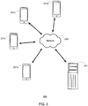
- Fig. 3 shows an example arrangement in which a server 251 (which may be comparable to the server 151 of Fig. 2 ) is connected over a wireless network 290 to several mobile end-user devices 201 a-d.
- the server in Fig. 2 is shown only to include memory, the server 151 may further be capable of accessing other external memories, data stores, or databases (not shown).
- information processed at the server 151 may be sent to an external data store (or database) to be stored, or may be accessed by the server 151 from the external data store (or database) for further processing.
- the system 100 may include multiple such data stores and/or databases.
- the data stores or databases may be separately accessible, such as each being accessible to a different server (e.g., a user identification database accessible to one server of the network, and a three-dimensional surface database accessible to a second server of the network).
- the data stores or databases described herein may not necessarily be separate, but may be stored together but as part of separate files, folders, columns of a table in a common file, etc.
- the server 151 is assigned the task of rendering the three-dimensional surface based on the information collected at the end-user device 101.
- the purpose of this arrangement is at least in part to relieve the end-user device 101 of performing the processing and carrying the hardware and/or software necessary to perform such rendering.
- the user does not have to purchase such hardware or software, or a device with a processor capable of performing such functions. Instead the user can merely transmit the data from their device 101 to some external location for processing.
- the present disclosure is not limited in terms of any particular server/processor arrangement. Rather, what is intended by the arrangement of Fig. 2 is to demonstrate one example system which provides the benefit of rendering the three-dimensional surface using devices external to the end-user device 101. Nonetheless, in other examples of the disclosure, if the end-user device 101 is properly equipped and contains enough processing power, the three-dimensional rendering hardware/software, may be included with the end-user device 101.
- the data for constructing a three-dimensional surface of the user's face may be collected by the user taking a video - or having another person take a video - of themselves using the built-in camera of their smart-phone, other mobile device, or other appropriately equipped end-user device.
- Taking a video may involve holding the camera at a distance from the user's face and the user turning their head side to side so that the camera captures various profiles of the user's face from various angles. Such profiles may include a front profile, side (left and right profiles), and other intermediary angles.
- Taking the video may further involve the user tilting their head up and down to capture additional profiles, and thus additional information about their facial contours and complexities, such as the underside of their nose.
- the camera instead of the user turning and tilting their head, the camera may be panned around the user's face, thus collecting profiles of the user's face from the same various angles.
- An additional video of the user's face may be taken in order to calibrate the information gathered from the first video. Taking this additional video may involve moving the camera close to and then away from their face. Preferably, the user will keep their head still for this video, so that the size of the user's head (or face) may be determined from the change in size of the user's head (or face), as imaged, as the camera moves towards and away from the user. Simply speaking, this additional video may provide information about the size of the user's head that is not necessarily available from the first video. It may also be used to calculate a scaling factor.
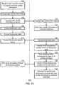
- Fig. 4 is a flow diagram of an example method 300 for an end-user device (e.g., in the example of Fig. 2 , end-user device 101), such as a smart-phone or tablet computer, to collect and transmit data sufficient for rendering a three-dimensional facial scan of the user.
- the end-user device collects various data using its inputs and sensors, performs some processing steps on the data, and then sends the partially processed data out (e.g., in the example of Fig. 2 , to server 151 of system 100) for further processing (e.g., three-dimensional rendering).
- the device collects video data from a first video scan of the user's face (at 302).
- the video data may include a plurality of video frames.
- the video frames may be taken from a plurality of angles relative to the user's face, and those angles may provide various profiles of the user's face.
- the video frames may be sequenced, such that identifiable landmark features of the user's face may be tracked frame-by-frame along the sequence of video frames.
- the video scan data may be collected by one or more image sensors and received by the device's processor, where a video file may be generated based on the video scan data.
- the device may optionally collect motion data (e.g., IMU data) during the first video scan.
- the motion data may include inertial measurements, such as indicating a change in motion or orientation of the device, during the first video scan. While it is not required that the user move the device during the first video scan, and may in fact be preferred that the user not move the device, the user may be holding the device in their hand during the video scan and thus, in the natural course of turning and tilting their head, may unknowingly or inadvertently move or tilt the device.
- collecting the motion data during the first video scan can help to stabilize the video information collected during the scan by indicating a change in the point of reference, or angle of reference, of the scanned video data.
- the motion data may be collected by the one or more motion sensors of the device, and like the video scan data, may also be provided to the device's processor, where a data file (optionally a text file) may be generated based on the motion data.
- a data file (optionally a text file) may be generated based on the motion data.
- the data file may be an IMU file in plain text format.
- the motion data may be correlated to the video scan data (e.g., mapped temporally over the duration of the video scan) at this stage (e.g., on the end-user device end) or a later stage (e.g., at a remote location) of processing (at 306).
- each of the video frames of the video scan data may be assigned a timestamp, and the motion data collected over time may similarly be assigned timestamps.
- an amount of delay between collection of the motion data and the video data may be known, and such delay may be factored into the timestamps in order to synchronize the motion and video data.
- the video scan and motion data may be correlated based on their respective time information (e.g., timestamps, time delay information).
- the correlated motion data may then be used to correct or compensate the collected video scan data, effectively creating a video scan taken from a single point and/or angle of reference.
- correlating motion data to the video scan data may be similarly useful to indicate whether the distance or angle of the camera changed during the scan. For example, if the camera were held closer to the user during a scan of the user's left profile than during a scan of the user's right profile, the video scan data may suggest that the left ear of the user is larger than the right ear. Thus, by collecting motion data, assuming that the user's face remained still during the video scan, it can be determined that, and how much, the camera moved away from the user's face from the left profile scan to the right profile scan, and the profiles may be corrected or compensated to yield a more accurate representation of the user's face.
- the motion data may include an instantaneous orientation measurement at the time of and corresponding to one of the collected video frames, and may further include one or more acceleration measurements during or between each of the collected video frames, in order to track tilting and movement of the camera during the first video scan.
- Fig. 5A shows a diagram representing an example of the data that may be collected during a video scan.
- the data includes a plurality of video frames 400 1 -400 n taken from a plurality of orientations 1-N (e.g., angles relative to the user's face).
- Each of the video frames may further be associated with time information (e.g., a timestamp) to indicate the specific time at which the frame was collected.
- the data further includes orientation information 410 1 -410 n concerning an orientation of the camera for each given time that the video frames 400 1 -400 n were collected.
- the data also includes motion information 420 1 -420 n-1 regarding a motion of the camera (e.g., three-dimensional acceleration measurements) between the specified times that each of the video frames 400 1 -400 n were collected. Specifically, shown in Fig.
- motion information 420 1 which concerns the motion of the camera between the time at which video frame 400 1 and video frame 400 2 were collected
- motion information 420 2 which concerns the motion of the camera between the time at which video frame 400 2 and video frame 400 3 (not shown) were collected
- motion information 420 11-1 which concerns the motion of the camera between the time at which video frame 400 n-1 (not shown) and video frame 400 n were collected.
- the orientation and motion information may be taken from an IMU file, or from other files containing data recorded by an IMU, accelerometer and/or gyrometer.
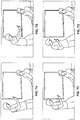
- Figs. 6A-6H show a user taking a video scan of their face from a plurality of angles relative to the user's face, in an example first video scan.
- the user first turns their head to the right (e.g., Fig. 6B ), then to the right (e.g., Fig. 6E ), and then tilts their head up (e.g., Fig. 6G ).
- the device may also collect scale estimation data from which a relative scale or size of the user's face may be estimated.
- the scale estimation data may be derived at least in part from information included in the first video scan data.
- scale estimation data may be derived at least in part from other known information (e.g., technical specifications of the camera, manually input information about the user's face, etc.)
- the scale estimation data may be derived from a second video scan of the user's face (at 308). Like the first video scan, the second video scan may include a plurality of video frames.
- the frames in the second video scan may be taken from the same angle relative to the user's face, but from a plurality of distances.
- the video frames (unlike photographs) may be sequenced such that identifiable landmark features of the user's face may be tracked frame-by-frame along the sequence of video frames.
- the first and second video scans may be created as separate video files.
- the first and second video scans may be portions of a single video file.
- the user or another person may take a single video of themselves, a first portion of such video involving the camera being held at various angles relative to the user's face, and a second portion involving the camera being moved towards and away from the user's face.
- the device may optionally collect acceleration data (e.g., IMU data) data during the second video scan (at 310).
- the acceleration data may be correlated with the second video scan data, at this step or at a later step of processing (at 312), as with the optional correlation of the first video scan (e.g., using timestamp information associated with each of the video frames and with the collected motion data, using time delay information between the video data and acceleration data collection, etc.), such that an acceleration of the device may be measured as the videoed subject (e.g., the user's face) of the second video scan gets larger and smaller (as the device moves toward and away from the subject).
- the combination of the video scan data and acceleration data may be used to determine an estimated scale of the videoed subject.
- the acceleration data may include an acceleration measurement at about the time of a corresponding one of the collected video frames, or may include a plurality of acceleration measurements between each of the collected video frames, in order to track overall displacement of the camera during the second video scan.
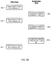
- Fig. 5B shows a diagram representing an example of the data that may be collected during a second video scan.
- the data includes a plurality of video frames 450 1 -450 n taken from a plurality of distances 1-N.
- Each of the video frames may further be associated with time information (e.g., a timestamp) to indicate the specification time at which the frame was collected.
- the data further includes information concerning an acceleration of the camera between the specified times of each of video frames 450 1 -450 n .
- acceleration data 460 1 which concerns the acceleration of the camera between the time at which video frame 450 1 and video frame 450 2 were collected.
- acceleration data 460 2 concerns the acceleration of the camera between the time at which video frame 450 2 and video frame 450 3 (not shown) were collected.
- Acceleration data 460 n-1 concerns the acceleration of the camera between the time at which video frame 450 n-1 (not shown) and video frame 450 n were collected.
- the acceleration data may be taken from an IMU file, or other file containing data recorded by an accelerometer.
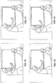
- Figs. 7A-7H shows a person taking a video scan of a user from a plurality of distances from the user's face, in an example second video scan.
- the camera is first moved in towards the user (e.g., Fig. 7B ), then moved out away from the user (e.g., Fig. 7D ), and then moved back in towards the user (e.g., Fig. 7F ).
- the camera cannot be zoomed in and out but rather physically moved towards and away from the user.
- acceleration data and video data may be correlated with one another based further on properties or features of the collected data itself, instead of solely based on timestamps. For example, identified features of the user's face may be measured in the individual frames of the video data. If there is determined to be a video frame for which a measured feature is largest, that video frame may be considered to have been taken at a greatest distance from the user's face. Thus, such a video frame may be correlated with a portion of the acceleration data determined to be collected at a distance farthest from the user's face (e.g., a point at which movement of the camera changes directions).
- a subset of video frames may be selected from the plurality of video frames collected during the video scan (at 314). This may be performed for either the first video scan or for the second video scan. In the case of both video scans, selecting the subset of video frames may be performed for purposes of efficiency. For instance, not all of the video frames of a video scan may be needed in order to track a user's facial features or to determine a scale of the user's face. In such a case, the device may only need to transmit a fraction or subset of the video frames, thus reducing bandwidth requirements (or speeding up) transmission of the video data.
- the video frames selected to be transmitted may be chosen based on one or more criteria. For example, with regard to first video scan data, the video frames associated with profiles of the user's face that are considered important for determining the shape of the user's face (e.g., front profile, left profile, right profile, etc.) may be selected. For further example, with regard to the video scan data that is correlated with motion data (including acceleration data), it may be that the motion data is collected at a rate slower than the video data is collected, such that only some video frames have the same timestamp as the motion data. In such a case, the video data having a timestamp the same as some of the motion data may be selected.
- the system may specify a predetermined video frame rate (e.g., 60 frames per second, 240 frames per second) preferred for rendering three-dimensional surfaces based on video data, and may select a sufficient number of video frames to meet this frame rate without further exceeding the frame rate.
- a predetermined video frame rate e.g. 60 frames per second, 240 frames per second
- the amount of motion data selected to be transmitted may similarly be reduced.
- the device may then transmit the collected data (at 316).
- the collected data may include the video frames of the first video scan data, the video frames of the second video scan data (e.g., video files), and optionally motion data associated with the first video scan and acceleration data associated with the second video scan (e.g., IMU files, other data files).
- the device's transmitter/receiver may perform this transmission, thereby sending the collected data to a remote destination.
- the transmitted data may be only a subset of the collected data if such subset of data is sufficient for constructing a three-dimensional surface of the user's face based on said data.
- a processor located remotely from the end-user device may receive and process the data in order to generate a three-dimensional surface representative of the user's face.
- 3D engine three-dimensional rendering engine
- Fig. 8 is a flow diagram of an example method 500 for a processor to generate a three-dimensional surface.
- the processor receives the transmitted video data.
- This video data may be the video data associated with the first and second scans of the user's face described in connection with Fig. 4 .
- the video data for the first video scan would include a plurality of video frames, the video frames having been taken from a plurality of angles relative to the user's face.
- the plurality of video frames may be the complete first video scan, or a select portion or subset of the video frames from the first video scan.
- the video data for the second video scan would include a plurality of video frames, the video frames having been taken from a plurality of distances from the user's face.
- the processor may also receive motion data associated with the first video scan, as well as receive acceleration data associated with the second video scan.
- the processor generates a three-dimensional representation of the user's face based at least on the plurality of video frames of the received video data.
- the video data used at 520 would be the first video scan data.
- the video frames of the first video scan include profiles of the user's face from a plurality of angles, such as a front profile, right side profile and left side profile, as well as other profiles with the user's head turned to the side or tilted up/down. Measurements of various facial features of the user, or anthropometric measurements, may be more accurately determined in one frame than another.
- the nasolabial angle may be more accurately determined from a side profile than a front profile
- mouth width may be more accurately determined from a front profile
- upper lip height may be more accurately determined from a front profile with the user's head tilted slightly upwards.
- Various angles of video frames may be relied on for measurements of different facial features.
- the processor In order for the processor to identify features of the user's face, the processor must initially detect the user's face in the video data. This may be accomplished using any face detection methodology known in the art. For example, the processor may search for features in the video frames (e.g., Haar-like features).
- the features may be representative of such features as the user's eyes (e.g., dark spot located vertically between light spots), the bridge of the user's nose (e.g., bright spot located horizontally between dark spots), and/or the user's eyes nose and mouth collectively (e.g., dark T-shaped spot between brighter spots for user's cheeks).
- Detection of features may involve use of cascade classifiers (e.g., using Haar feature-based cascade classifiers), such that only a few classifiers may be needed to rule out portions of the video frames that do not portray the user's face, or do not portray a specific profile (e.g., front profile, side profile) of the user's face.
- cascade classifiers e.g., using Haar feature-based cascade classifiers
- Such classifiers help to increase the overall speed of performing feature detection.
- Landmark features of the user's face may be identified based on the detected features.
- Landmark features may be points on the user's face that are tracked from frame to frame (e.g., a corner of the user's eye), or may be larger features as a whole (e.g., the user's eye) In either, boundaries between light and dark spots on the video frames may be used to identify the landmark features.
- the edge of the user's eye may appear darker than the skin around it; therefore, the edges of the user's eye may be detected based on boundaries between bright and dark portions of a given video frame.
- the processor may disregard that frame (e.g., delete the frame from the received data set) for the remainder of the processing steps.
- generating a three-dimensional surface representative of the user's face may further involve using a standard morphable face model.
- the morphable face model begins with a three-dimensional surface representative of an average persons' face.
- the three-dimensional surface serves as a template from which to build a customized surface.
- the template surface may be a generic face, non-specific as to gender, age, or build of user. However, in some applications, it may be preferable to use a template that is a relatively generic face but at least partially biased towards gender, age and/or build factors. For instance, older individuals may be more likely to order a custom-fit CPAP mask than would a younger individual. Therefore, the template surface used for customizing a CPAP mask may be a generic face biased towards the shape or features of an older and/or overweight individual's face.
- the morphable face model may then morph or adjust the template surface into a customized surface based on an analysis of the received plurality of video frames.
- the morphable face model may be configured to morph specific features of the user's face (e.g., nasolabial angle, alar angle, lip height, mouth width, nose width) based on information derived from the plurality of video frames. Such derived information may be obtained from an analysis of the landmark features identified in the video frame. For instance, if the width of the user's mouth in one video frame is determined to be larger than the mouth width of the template surface, then the mouth of the template surface may be morphed slightly to increase in width. In such a case, the degree of such morphing may be determined by several factors, such as the particular frame being evaluated (e.g., more weight for a front profile than a side profile when evaluating mouth width), or the number of frames in which the determination is made.
- Changes to the template surface may be made as the plurality of video frames are being analyzed. For instance, a small morphing of the morphable surface may be made after each analyzed video frame. In such a case, the next video frame may be compared to the morphed template surface, or may still be compared to the initial template surface, in order to effect additional changes to the surface. For instance, a difference between an identified landmark feature of the analyzed video frame and a corresponding feature of the template surface may be calculated, and the calculated difference may be used to modify the template surface.
- the changes to the template surface may be made after all of the plurality of video frames have been analyzed.
- points and/or landmarks of the user's face may be identified and tracked frame-by-frame (as described below), and the morphable model may be generated based on those points and/or landmarks.
- the user's face may first be scaled (also as described below) prior to the morphable model being generated.
- the morphable model may still improve the three-dimensional representation rendered from the tracked video frames by modifying the representation based on known characteristics of the user (e.g., age, gender, build, etc.).
- the custom surface may be generated entirely from points or features tracked in the plurality of video frames.
- the points may be the landmark features described above in connection with Fig. 8 .
- the surface of a user's face includes many complex geometric features and contours, it may be desirable to track at least about 50 points on the user's face in order to generate a relatively accurate representation of the user's face. Additional points may be added, at the cost of computing power and/or computing time, in order to further improve accuracy of the three-dimensional surface. In some cases, about 80 points, about 132 points, or even more points may be used.
- the points may be representative of (i) points of a user's face that are easily detectable using the processor, (ii) points of a user's face that are significantly variable from one individual to another, (iii) points of a user's face that are located in places where fitting apparatus or apparel on the user's face may ensure a seal against the user's face and/or may be prone to cause discomfort to the user (e.g., for a mask: around the user's mouth, for eyeglasses: on the bridge of the user's nose, etc.), (iv) points of a user's face that are related to measurements of the user's face (e.g., anthropometric measurements) to be derived from the analysis, or any combination of the above.
- measurements of the user's face e.g., anthropometric measurements
- At least some of the points may be representative of the user's eyes, at least some of the points may be representative of the user's nose, and at least some of the points may be representative of the user's mouth. In other examples, at least some points may be representative of an edge of the user's face.
- the edge of the user's face may be defined as, for a given video frame, a boundary between the user's face and the background of the given video frame. Other features may also contribute to the defining the edge of the user's face, such as the user's ears and chin.
- the points may be arranged in an array, such that the processor attempts to scale and fit the array to match with the detected features of the user's face. Spacing between points on the array is not fixed. This enables certain points to move independent of one another as the user turns or tilts their head in the video scan. Depth of certain facial features may be measured as the user turns or tilts their head. For example, considering the tip of the user's nose, if a first point is located to represent the tip of the user's nose, and a second point is located at the nasolabial groove, as the user turns to their left or right in the video scan, the first point will move a greater distance laterally than will the second point. The relative rates at which those points move may indicate a difference in distance from the camera, and thus indicate a depth dimension between those points. (Such depth may further be measured, or confirmed, based on a side profile video frame of the user.)
- One drawback of searching for an array of points on the user's face is that, in some cases, when the user turns or tilts their head, some of the points of the array are no longer visible.
- the processor may then either incorrectly track those points on the video frame, or lose track of the user's face entirely.
- it may be desirable that at least some of the points be grouped into discrete regions representative of larger features of the user's face (e.g., left eye, right eye, mouth, etc.).
- the processor may determine to cease detection of that discrete region, but may proceed to gather information about other discrete regions of the user's face. For example, if the user's left and right eyes are part of separate discrete regions, then if the user turns their head to the user's right, the user's right eye may drop out of the frames of the video scan and tracking of the right eye may be ceased, while tracking of the left eye, still in view, may continue to be performed.
- the user's nose and eyes are part of separate discrete regions, then if the user tilts their head upwards, the user's eyes may drop out of the video scan and tracking of the eyes may be stopped, while tracking of the nose, still in view, may continue to be performed.
- points of the user's face are bundled into a discrete group (such as a number of points around the edge of a user's eye, or along a boundary of the user's lips) movement of those points may further be tracked as a group.
- the processor may recognize a coordinated motion of the identified group of points.
- the movement of one point may influence the movement of other related points (e.g., movement of a point related to the left corner of a person's lips may indicate a similar movement of a point related to the right corner of the lips).
- Such "rules” may be used to further control the point-by-point tracking and increase overall accuracy of the tracked points.
- the motion data may provide further degree of stabilization to improve tracking points and/or measuring of features of the user's face.
- Point-by-point tracking may further be enhanced with the use of a machine learning algorithm.
- the machine learning algorithm may be trained to recognize the movement of individual points, or discrete groups of points, on a user's face based on a larger training dataset.
- the training dataset may be stored in a memory of the one or more servers, and may include a plurality of three-dimensional surfaces representative of a plurality of users' faces.
- the training dataset may further include information relating to identified points on those faces tracked along a series of frames.
- the machine learning algorithm may learn how the individual points of a user's face tend to move as the face turns and tilts as a whole.
- the motion of the points on the faces of the larger dataset may further be manually evaluated, and the algorithm may be manually corrected in cases where points are not correctly tracked, thus further enhancing the algorithm's ability to learn from the training dataset.
- the machine learning algorithm may be utilized to generate a support vector machine or other supervised learning model to classify and recognize points or landmarks on the user's face, frame by frame.
- the processor scales the three-dimensional representation of the user's face based at least on the plurality of video frames of the received video data.
- the video data used for scaling may be from the first video scan.
- the video data may be a front facing profile view of the user, in which a size of a preselected feature, or distance between two preselected features, may be measured to gain a relatively accurate measure of the scale of the user's face.
- interpupil distance for example, it has been found that the features of the user's face can be measured and scaled to within about 3 mm accuracy.
- a marker e.g., a sticker, QR code, etc.
- a known geometry e.g., diameter
- the geometry of the marker e.g., changes from circle to oval shape
- an angle of the camera relative to the user's face for a given frame may be determined based on the shape of the marker in the frame (or from changes in the shape of the marker from one frame to the next).
- the user may wear a mesh or mesh-like net over their face.
- the holes of the net may be of a known size, such that they function like a marker of known size on the user's face.
- the holes of the net may be constructed with a known pattern or geometry, such that when the net is worn by the user, the shape of net deforms (e.g., conforms to contours of the user's face). The deformed shapes of the net may then be captured in the video frames, and analyzed to identify contours of the user's face.
- a distance of the user from the camera may be determined by placing a transmitter on the user's face and capturing a signal from the transmitter during the videoing process.
- the transmitter can emit a signal with a known signal strength, such that the strength of the received signal at the camera may be indicative of a distance between the camera and transmitter.
- the transmitter may further transmit time information, such that the signal strength measurements may be correlated to specific video frames based on the time information.
- the "time information" of the transmitted signal may be the time that such signal is received at the device)
- a measurement of a given feature may be manually entered into the device by the user.
- a single video frame may be chosen as the frame for measuring the manually input measurement.
- the remaining video frames may be assumed to be taken from the same distance to the user as the chosen video frame.
- the video data used for scaling may be from the second video scan, as well as from acceleration data collected in connection with the second video scan (e.g., IMU data). Knowing the acceleration of the camera from frame to frame (which itself involves correlating the acceleration data with the respective video frames), in combination with analyzing the relative size of the user as imaged from frame to frame, may provide sufficient information as to the user's actual distance from the camera during the second video scan. For example, the formula arg s min ⁇ s ⁇ 2 p v - Da I ⁇ , as presented by Christopher Ham et al., Hand Waving Away Scale, Computer Vision - ECCV 2014: 13th European Conference, Zurich, Switzerland, Sept.
- a scaling factor of the user's face may be determined.
- Figs. 3 and 8 provide some examples of how a user can obtain a scaled three-dimensional rendering of their face using only their mobile phone or other camera-equipped portable communications device. However, there are other ways to obtain a scaled three-dimensional rendering of a user's face.
- the user may utilize two or more lenses to capture three-dimensional data of the user's face.
- the mobile device may include two or more cameras (e.g., stereoscopic cameras) with a known distance between the cameras. Images from the two or more cameras may then be resolved with one another to derive a depth of the subject in the images (similar to how a pair of eyes provides depth perception).
- the user may utilize two or more devices for capturing video of the user's face.
- the two devices may communicate with each other wirelessly (e.g., Bluetooth).
- a linear distance between the devices may be determined based on signal strength of the communication signal therebetween.
- the linear distance may then be utilized in combination with the captured video frames from the two devices (which may be related to one another based on time information) in order to determine a scaling factor of the user's face.
- the two devices may be kept at a fixed distance from one another.
- the devices may be connected by a beam or shaft and caused to rotate around the users head.
- the devices may further be connected to a helmet that the user wears on their head.
- each of the devices may be mounted to a rotatable shaft mounted at the top of the helmet.
- the rotatable shaft may extend away from the user in the axial plane of the user.
- Each end of the rotatable shaft may be equidistant from the mounting point of the helmet, and may be connected to a corresponding arm extending downward from the shaft.
- the devices may be mounted from the respective arms such that each of the devices is held by the arm at about the height of the user's face and at a known distance away from the user.
- the arms may be rotated manually by the user, or automatically by a motor, thereby causing the devices to capture video of the user's face as they rotate around the user.
- the rotatable shaft may also be fitted with a linear encoder to provide information about the angle of rotation.
- the linear encoder may further be synchronized with the video frames captured by the devices to provide input to later processing steps. Having the devices capture video frames of the user from a fixed distance means that the scaling factor of the user's face may be calibrated and known without having to analyze the video frames. Thus, in such cases, additional techniques or features to determine a scaling factor on a scan by scan basis are not necessary.
- a single device may be used to capture video frames of the user from a plurality of angles without the device or user moving. This may be accomplished by positioning a rotatable prism between the device and the user, and further positioning a movable mirror behind the user (from the perspective of the device).
- the prism and mirror may be connected to one another using a rig, such that both the prism and mirror are mounted to the rig.
- the rig may be operable to rotate the mirror in a circle around the user such that the plane of the mirror is kept perpendicular to the user as it moves around the user.
- the rig may be operable to rotate the prism in place.
- the mirror and prism may rotate in opposite directions (clockwise/counterclockwise, vice versa).
- images from all around the user may be captured by reflecting light through the prism and off the mirror. Since the distance between the device and user may be fixed and known (as well as the distance from the device to prism, prism to mirror, and mirror to user) scaling may be known without calculation or estimation.
- Another way of measuring a scaling factor associated with a user's face involves use of a camera that includes an adjustable focus. Distance of the user's face from the camera may then be determined by adjusting the focal length until the face comes in and out of focus. In such a case, slices of the user's face at varying depths may be captured, and the three-dimensional model may be constructed from those slices.
- the camera may be capable of capturing video frames using different focal lengths simultaneously.
- the focal lengths may be adjusted to cause certain feature of the user's face to come in and out of focus. Given the focal lengths at which the features of the user's face come in and out of focus, and given further knowledge of the technical specifications of the camera, the distance of the user's face from the camera may be determined.
- a further way of measuring a scaling factor associated with a user's face involves use of an ultrasonic and/or electromagnetic measuring device integrated with the camera.
- the device may be operable to emit an ultrasonic or electromagnetic signal, and measure the time delay between transmission and return of the reflected signal. The time delay may in turn be used to measure a distance between the camera and the user's face.
- the device may be capable of emitting structured light, such as from a flash bulb.
- the pattern of the light may be cast on the user's face. Assuming that the pattern is known, the size of the pattern in a given video frame is indicative of the distance of the subject on which the light is cast.
- such distance measurements may further be utilized in the generation of a 3D model of the user's face.
- the distance information may be used to track a z-coordinate of the user's face (in and out of the video frame) if the distance between the device and face change at any time during the videoing process.
- the three-dimensional surface engine may rely on the collected or known distance information in order to perform image stitching of the collected video frames.
- the end-user device may further be configured for communicating with a designer and/or vendor of custom-fit apparatus and apparel in order to order or purchase an article for the user based on the rendered surface.
- the same system used for taking a video scan of the user's face can also be used for enrolling the user in a service that designs articles based on the video scan.
- a user enrollment system may be constructed in the same manner as the system shown in Fig. 2 , having one or more end-user devices connected to one or more servers.
- one or more servers may be dedicated for the purpose of gathering identification and/or enrollment information about a user, and one or more other servers may be dedicated for the purpose of collecting the user's video scans and rendering three-dimensional surfaces based on those scans.
- the user's rendered surface and personal information may likewise be stored in different databases or data stores.
- Such an arrangement may provide for additional security for the user's personal information on one secure database, without having to securely store excess amounts of data that do not require the same level of security (e.g., a de-indentified rendered surface of the user's face).
- Fig. 9 shows a flow of information within an example user enrollment system 600.
- the user enrollment system 600 may include one or more end-user devices 610, a customer information system 620 (which is a subsystem of the user enrollment system 600), a three-dimensional surface engine (3D engine) 630, and one or more databases.
- information may be generated at the end-user device 610, and subsequently transmitted to the customer information system 620 and 3D engine 630, or vice versa.
- Such information generated at the end-user device 610 may include a user profile 612 and video scan data 614.
- the user profile 612 may include such information as one or more unique identifiers of the user (including a unique identifier for the user's scans), a username of the user, a password.
- the video scan data 614 may include such information as the plurality of video frames from the video scan, motion and/or acceleration data (e.g., IMU data) from a built-in motion sensor, and datetime stamps identifying a specific time that the video frames and/or motion/acceleration data are collected.
- the user profile 612 which includes personal information of the user, may be transmitted to the customer information system 620, where the user's personal information may be stored.
- the customer information system 620 also includes a sign-up or enrollment subsystem 622 for signing up or enrolling a user in a program for designing an apparatus or article for the user to wear on their face, as well as a database for storing customer orders 624.
- the customer information system 620 effectively serves as a hub for customers and vendors, so that a vendor who is contracted to design a customized apparatus or article for the user can easily and conveniently access the three-dimensional rendering of the user's face previously generated and uploaded by the user.
- the customer information system 620 may further include clinical information, such as in a clinical information database 626, regarding the user.
- Clinical information may include any information that is important for a vendor to be aware of when designing the apparatus or article for the user (provided that the vendor is privileged to such information), and may further include information required for accessing the rendered surface of the user's face.
- the user may also transmit information to other systems that provide services to customers, such as a processor or engine for rendering three-dimensional surfaces.
- a processor or engine for rendering three-dimensional surfaces.
- additional information may be processed based on the video scan data. For instance, certain video frames may be selected, and the number of selected video frames may be recorded.
- a video scan transmission 616 from the end-user device 610 to the 3D engine 630 may then include the video frames and/or the selected video frames (in some cases, all of the video frames may be transmitted with the selected ones identified), the number of selected video frames, the motion/acceleration data, the user's unique identifier, and the datetime stamps. This information may then be used by the 3D engine 630 to produce a representation of a three-dimensional surface 632.
- the representation of the three-dimensional surface 632 includes an object file including the rendered surface representative of the user's face, as well as the user's unique identifier in order to associate the surface 632 with its user.
- the representation may a plain text file including a list of data points, landmarks, measurements and/or other dimensions derived from analysis of the user's face in the video data.
- the information of the text file may be utilized in order to customize an article associated with the user's face.
- the three-dimensional surface 632 may be stored in a database 642 dedicated for storing object files.
- the object files may be stored de-identified, or anonymously.
- the object file may have a title or unique identifier other than the user's name or the user's unique identifier.
- the object file may then be accessed based on other information, such as a unique scan identifier, or a unique three-dimensional surface identifier.
- the object file is assigned a unique three-dimensional surface identifier, which is associated with the user's unique identifier in a customer reference file 652 and stored in a separate location.
- the customer reference file 652 is stored in a clinical information database 626 of the customer information system 620.
- the object file may be accessed based on the unique identifier of the user based on the customer reference file 652 stored at the customer information system.
- the 3D engine 630 may further compile a video file 634 simulating movement of the rendered surface.
- the rendered surface may be shown as turning to the sides and/or tilting up and down in order that a viewer of the video file 634 may gain an understanding of the three-dimensional properties of the user's face based on the video.
- the rendered surface of the video file 634 may further include a superimposition of a grid over the user's face.
- the superimposed grid may close fit the contours of the user's face, such that the grid is indicative of changes in depth (e.g., indicating the edges of the user's face, indicating the sides and curvature of the user's nose, indicating roundness or flatness of the user's cheeks, etc.).
- Use of such a grid may further improve the viewer's understanding of the three-dimensional properties of the user's face.
- the video file 634 may be transmitted from the 3D engine 630 back over the network to the end-user device 610.
- the customer information system 620, 3D engine 630 and databases 642/652 may be located across a plurality of servers in a network.
- the end-user device 610 may then connect to any of those remote servers over the network, either by wired or wireless connection.
- Fig. 10 shows an example flow diagram 700 of operations performed during use of a user enrollment system, such as the user enrollment system 600 of Fig. 9 .
- an end-user device e.g., in the example of Fig. 9 , end-user device 610) receives an input from the user requesting to enroll in a program for designing a custom-fit mask.
- the device may also receive profile information of the user that may be used to create the user's profile in the enrollment program.
- the device may encrypt the user's profile information, and at 706 may transmit the user profile information to the customer information system (e.g., in the example of Fig. 9 , customer information system 620).
- the customer information system e.g., in the example of Fig. 9 , customer information system 620.
- the customer information system may receive and decrypt the user's enrollment request and profile information, including the unique identifier of the user.
- the profile information is stored in a customer database, where it may accessible to one or more vendors from whom the user purchases a custom-fit apparatus or other apparel.
- the device may collect facial scan data based on a prompt from the user requesting that such facial scan data be collected.
- the facial scan data may include any of the video frames and corresponding motion/acceleration data described previously in this specification.
- the facial scan data may also include timestamp information by which the video frames and other data may be temporally correlated to one another such that they may be combined during later processing (e.g., at the 3D engine).
- the facial scan data may include each of profile images of the user as well as stabilization and/or scaling data (e.g., the first and second video scans of the example of Fig. 4 ).
- the facial scan data may also include information designating a pre-selected subset of video frames, such that a priority for using the preselected subset of video frames may be applied by the 3D engine during further processing.
- a pre-selected subset of video frames may be an indication of the total number of pre-selected frames.
- the facial scan data may be encrypted to secure transmission.
- the encrypted facial scan data may be transmitted, for instance to a remote processor, for three-dimensional rendering.
- the facial scan data may be encrypted and transmitted along with a request for production of a customized article (e.g., patient interface).
- the request may further include the unique identifier of the user so that the video scan data may be correlated to a specific user's face.
- the profile information and facial scan data is shown as being generally transmitted to the same remote location.
- the remote location may include multiple servers and or multiple processors, and the profile information and facial scan data may be transmitted to different servers and/or different processors for handling, processing and storage.
- the processor decrypts the facial scan data, and at 732, the processor renders a three-dimensional surface based on the facial scan data.
- the three-dimensional surface may then be saved, at 734, to a database, such a dedicated database for such rendered surfaces.
- the three-dimensional surface may also, at 736, be transmitted back to the end-user device.
- the transmitted file may be a video file, which may be played back to the user by the end-user device at 740.
- Fig. 11 shows example frames from such a video file, in which a three-dimensional representation of a user's face turns side to side and tilts up and down, and further including a grid laid over the three-dimensional representation.
- the three-dimensional surface may be associated or otherwise linked with the user profile information in a customer database.
- the customer database may be separate from the three-dimensional surface database.
- a vendor who is interested in accessing the three-dimensional surfaces may interact with the associated information in the customer database instead of directly accessing the three-dimensional surface.
- the above method illustrates how a user can, with a simple video scan from their mobile phone, conduct an online transaction that enables the design and production of a custom-fit article or apparatus.
- the customer information system may further include a marketplace to conduct and complete monetary transactions, so that user's may easily order, and vendors may easily fulfill orders for, customized wearables for the user's face.
- One application for this technology is for obtaining a mask or a patient interface for interfacing with a respiratory pressure therapy device such as a CPAP machine.
- a processor may be configured to determine and/or identify a particular mask, mask-related component, mask size and/or size of a mask-related component, such as from a plurality of mask sizes and/or a plurality of sizes of mask-related components, based on the generated three dimensional surface.
- a processor may be configured to compare dimensions from the generated three dimensional surface to associated dimensions of pre-existing interfaces, such as off-the-shelf respiratory masks (e.g., nasal, mouth and nose, etc. such as for a respiratory breathable gas therapy), to select a suitable size of such pre-existing interface or mask based on one or more dimensions of the rendered three dimensional surface and one or more dimensions of the pre-existing interfaces or masks.
- pre-existing interfaces such as off-the-shelf respiratory masks (e.g., nasal, mouth and nose, etc. such as for a respiratory breathable gas therapy)
- a selected mask with such an automated process may be offered, recommended to, or provided to the user based on dimensions from the rendered surface.
- one or more dimensions may be applied to a manufacturing process to custom manufacture such a mask or mask component for the particular user based on the one or more dimensions from the three dimensional rendered surface of the particular user.
- a processor such as one of or associated with a manufacturing system, may be configured to determine one or more dimensions from the generated three dimensional surface for setting a manufacturing apparatus to produce a mask or mask component according to or based on the determined dimension(s).
- other articles such as glasses, sunglasses, costumes, etc., may also be customized using the same technology (e.g., video scans, enrollment system, etc.).
- Fig. 12 shows a non-invasive patient interface 3000 in accordance with one aspect of the present technology.
- the patient interface comprises the following functional aspects: a seal-forming structure 3100, a plenum chamber 3200, a positioning and stabilizing structure 3300 and one form of connection port 3600 for connection to air circuit 4170.
- a functional aspect may be provided by one or more physical components.
- one physical component may provide one or more functional aspects.
- the seal-forming structure 3100 is arranged to surround an entrance to the airways of the patient so as to facilitate the supply of air at positive pressure to the airways.
- a seal-forming structure 3100 provides a seal-forming surface, and may additionally provide a cushioning function.
- a seal-forming structure 3100 in accordance with the present technology may be constructed from a soft, flexible, resilient material such as silicone.
- the seal-forming structure 3100 comprises a sealing flange 3110 and a support flange 3120.
- the sealing flange 3110 comprises a relatively thin member with a thickness of less than about 1 mm, for example about 0.25 mm to about 0.45 mm, that extends around the perimeter 3210 of the plenum chamber 3200.
- Support flange 3120 may be relatively thicker than the sealing flange 3110.
- the support flange 3120 is disposed between the sealing flange 3110 and the marginal edge 3220 of the plenum chamber 3200, and extends at least part of the way around the perimeter 3210.
- the support flange 3120 is or includes a spring-like element and functions to support the sealing flange 3110 from buckling in use. In use the sealing flange 3110 can readily respond to system pressure in the plenum chamber 3200 acting on its underside to urge it into tight sealing engagement with the face.
- the seal-forming portion of the non-invasive patient interface 3000 comprises a pair of nasal puffs, or nasal pillows, each nasal puff or nasal pillow being constructed and arranged to form a seal with a respective naris of the nose of a patient.
- Nasal pillows in accordance with an aspect of the present technology include: a frusto-cone, at least a portion of which forms a seal on an underside of the patient's nose, a stalk, a flexible region on the underside of the frusto-cone and connecting the frusto-cone to the stalk.
- the structure to which the nasal pillow of the present technology is connected includes a flexible region adjacent the base of the stalk.
- the flexible regions can act in concert to facilitate a universal joint structure that is accommodating of relative movement both displacement and angular of the frusto-cone and the structure to which the nasal pillow is connected.
- the frusto-cone may be axially displaced towards the structure to which the stalk is connected.
- the non-invasive patient interface 3000 comprises a seal-forming portion that forms a seal in use on an upper lip region (that is, the lip superior ) of the patient's face.
- the non-invasive patient interface 3000 comprises a seal-forming portion that forms a seal in use on a chin-region of the patient's face.
- the plenum chamber 3200 has a perimeter 3210 that is shaped to be complementary to the surface contour of the face of an average person in the region where a seal will form in use. In use, a marginal edge 3220 of the plenum chamber 3200 is positioned in close proximity to an adjacent surface of the face. Actual contact with the face is provided by the seal-forming structure 3100.
- the seal-forming structure 3100 may extend in use about the entire perimeter 3210 of the plenum chamber 3200.
- the seal-forming portion 3100 of the patient interface 3000 of the present technology may be held in sealing position in use by the positioning and stabilizing structure 3300.
- a positioning and stabilizing structure 3300 is provided that is configured in a manner consistent with being worn by a patient while sleeping.
- the positioning and stabilizing structure 3300 has a low profile, or cross-sectional thickness, to reduce the perceived or actual bulk of the apparatus.
- the positioning and stabilizing structure 3300 comprises at least one strap having a rectangular cross-section. In one example the positioning and stabilizing structure 3300 comprises at least one flat strap.
- a positioning and stabilizing structure 3300 comprises a strap constructed from a laminate of a fabric patient-contacting layer, a foam inner layer and a fabric outer layer.
- the foam is porous to allow moisture, (e.g., sweat), to pass through the strap.
- the fabric outer layer comprises loop material to engage with a hook material portion.
- a positioning and stabilizing structure 3300 comprises a strap that is extensible, e.g. resiliently extensible.
- the strap may be configured in use to be in tension, and to direct a force to draw a cushion into sealing contact with a portion of a patient's face.
- the strap may be configured as a tie.
- a positioning and stabilizing structure 3300 comprises a strap that is bendable and e.g. non-rigid.
- An advantage of this aspect is that the strap is more comfortable for a patient to lie upon while the patient is sleeping.
- the patient interface 3000 includes a vent 3400 constructed and arranged to allow for the washout of exhaled carbon dioxide.
- vent 3400 in accordance with the present technology comprises a plurality of holes, for example, about 20 to about 80 holes, or about 40 to about 60 holes, or about 45 to about 55 holes.
- the vent 3400 may be located in the plenum chamber 3200.
- the vent 3400 is located in a decoupling structure 3500, e.g., a swivel 3510.
- the patient interface 3000 includes at least one decoupling structure 3500, for example, a swivel 3510 or a ball and socket 3520.
- Connection port 3600 allows for connection to the air circuit 4170.
- the patient interface 3000 includes a forehead support 3700.
- the patient interface 3000 includes an anti-asphyxia valve 3800.
- a patient interface 3000 includes one or more ports that allow access to the volume within the plenum chamber 3200. In one form this allows a clinician to supply supplemental oxygen. In one form, this allows for the direct measurement of a property of gases within the plenum chamber 3200, such as the pressure.
- Anti-asphyxia valve The component or sub-assembly of a mask system that, by opening to atmosphere in a failsafe manner, reduces the risk of excessive CO 2 rebreathing by a patient.
- Elbow A conduit that directs an axis of flow of air to change direction through an angle.
- the angle may be approximately 90 degrees. In another form, the angle may be less than 90 degrees.
- the conduit may have an approximately circular cross-section. In another form the conduit may have an oval or a rectangular cross-section.
- Frame in the context of a hardware component of a mask, will be taken to mean a mask structure that bears the load of tension between two or more points of connection with a headgear.
- a mask frame may be a non-airtight load bearing structure in the mask. However, some forms of mask frame may also be airtight.
- Headgear will be taken to mean a form of positioning and stabilizing structure designed for use on a head.
- the headgear comprises a collection of one or more struts, ties and stiffeners configured to locate and retain a patient interface in position on a patient's face for delivery of respiratory therapy.
- Some ties are formed of a soft, flexible, elastic material such as a laminated composite of foam and fabric.
- Curvature (of a surface) A region of a surface having a saddle shape, which curves up in one direction and curves down in a different direction, will be said to have a negative curvature. A region of a surface having a dome shape, which curves the same way in two principal directions, will be said to have a positive curvature. A flat surface will be taken to have zero curvature.
- Floppy A quality of a material, structure or composite that is one or more of:
- the quality of being floppy may have an associated direction, hence a particular material, structure or composite may be floppy in a first direction, but stiff or rigid in a second direction, for example a second direction that is orthogonal to the first direction.
- any and all components herein described are understood to be capable of being manufactured and, as such, may be manufactured together or separately.
- example method 300 example method 500 user enrollment system 600 end user device 610 user profile 612 video scan data 614 video scan transmission 616 customer information system 620 enrollment subsystem 622 customer orders 624 clinical information database 626 engine 630 three dimensional surface 632 video file 634 database 642 customer reference file 652 example flow diagram 700 mobile end user devices 201 a-d patient interface 3000 seal - forming structure 3100 sealing flange 3110 support flange 3120 plenum chamber 3200 entire perimeter 3210 marginal edge 3220 structure 3300 vent 3400 decoupling structure 3500 swivel 3510 socket 3520 connection port 3600 forehead support 3700 anti - asphyxia valve 3800 video frame 400 1 video frame 400 2 video
Landscapes
- Health & Medical Sciences (AREA)
- Engineering & Computer Science (AREA)
- General Health & Medical Sciences (AREA)
- Public Health (AREA)
- Life Sciences & Earth Sciences (AREA)
- Biomedical Technology (AREA)
- Physics & Mathematics (AREA)
- Veterinary Medicine (AREA)
- Animal Behavior & Ethology (AREA)
- Heart & Thoracic Surgery (AREA)
- Theoretical Computer Science (AREA)
- Medical Informatics (AREA)
- Anesthesiology (AREA)
- Pulmonology (AREA)
- Hematology (AREA)
- Oral & Maxillofacial Surgery (AREA)
- Emergency Medicine (AREA)
- General Physics & Mathematics (AREA)
- Epidemiology (AREA)
- Primary Health Care (AREA)
- Multimedia (AREA)
- Software Systems (AREA)
- Surgery (AREA)
- Nuclear Medicine, Radiotherapy & Molecular Imaging (AREA)
- Computer Vision & Pattern Recognition (AREA)
- Pathology (AREA)
- Human Computer Interaction (AREA)
- Computing Systems (AREA)
- Data Mining & Analysis (AREA)
- Biophysics (AREA)
- Molecular Biology (AREA)
- Radiology & Medical Imaging (AREA)
- Evolutionary Computation (AREA)
- General Engineering & Computer Science (AREA)
- Mathematical Physics (AREA)
- Geometry (AREA)
- Artificial Intelligence (AREA)
- Dentistry (AREA)
- Urology & Nephrology (AREA)
- General Business, Economics & Management (AREA)
Priority Applications (1)
| Application Number | Priority Date | Filing Date | Title |
|---|---|---|---|
| EP25183008.9A EP4651105A3 (de) | 2015-11-25 | 2016-11-25 | Verfahren und systeme zur bereitstellung von schnittstellenkomponenten für die atemtherapie |
Applications Claiming Priority (2)
| Application Number | Priority Date | Filing Date | Title |
|---|---|---|---|
| US201562259743P | 2015-11-25 | 2015-11-25 | |
| EP16200746.2A EP3182311B1 (de) | 2015-11-25 | 2016-11-25 | Verfahren und systeme zur bereitstellung von schnittstellekomponenten für die atemtherapie |
Related Parent Applications (1)
| Application Number | Title | Priority Date | Filing Date |
|---|---|---|---|
| EP16200746.2A Division EP3182311B1 (de) | 2015-11-25 | 2016-11-25 | Verfahren und systeme zur bereitstellung von schnittstellekomponenten für die atemtherapie |
Related Child Applications (1)
| Application Number | Title | Priority Date | Filing Date |
|---|---|---|---|
| EP25183008.9A Division EP4651105A3 (de) | 2015-11-25 | 2016-11-25 | Verfahren und systeme zur bereitstellung von schnittstellenkomponenten für die atemtherapie |
Publications (2)
| Publication Number | Publication Date |
|---|---|
| EP3913636A1 true EP3913636A1 (de) | 2021-11-24 |
| EP3913636B1 EP3913636B1 (de) | 2025-06-18 |
Family
ID=57406129
Family Applications (3)
| Application Number | Title | Priority Date | Filing Date |
|---|---|---|---|
| EP21164373.9A Active EP3913636B1 (de) | 2015-11-25 | 2016-11-25 | Verfahren und systeme zur bereitstellung von schnittstellenkomponenten für die atemtherapie |
| EP16200746.2A Active EP3182311B1 (de) | 2015-11-25 | 2016-11-25 | Verfahren und systeme zur bereitstellung von schnittstellekomponenten für die atemtherapie |
| EP25183008.9A Pending EP4651105A3 (de) | 2015-11-25 | 2016-11-25 | Verfahren und systeme zur bereitstellung von schnittstellenkomponenten für die atemtherapie |
Family Applications After (2)
| Application Number | Title | Priority Date | Filing Date |
|---|---|---|---|
| EP16200746.2A Active EP3182311B1 (de) | 2015-11-25 | 2016-11-25 | Verfahren und systeme zur bereitstellung von schnittstellekomponenten für die atemtherapie |
| EP25183008.9A Pending EP4651105A3 (de) | 2015-11-25 | 2016-11-25 | Verfahren und systeme zur bereitstellung von schnittstellenkomponenten für die atemtherapie |
Country Status (2)
| Country | Link |
|---|---|
| US (3) | US10220172B2 (de) |
| EP (3) | EP3913636B1 (de) |
Families Citing this family (29)
| Publication number | Priority date | Publication date | Assignee | Title |
|---|---|---|---|---|
| US11235119B2 (en) | 2013-03-15 | 2022-02-01 | Lucy Carol Davis | Facial mask apparatus and method of making |
| US11235120B2 (en) | 2013-03-15 | 2022-02-01 | Lucy Carol Davis | Facial mask apparatus with removable filter |
| CN119345549A (zh) | 2015-06-30 | 2025-01-24 | 瑞思迈私人有限公司 | 使用移动应用的面罩大小调整工具 |
| USD800895S1 (en) | 2015-09-25 | 2017-10-24 | Fisher & Paykel Healthcare Limited | Face mask cushion |
| USD784516S1 (en) | 2015-09-25 | 2017-04-18 | Fisher & Paykel Healthcare Limited | Face mask frame |
| USD784515S1 (en) | 2015-09-25 | 2017-04-18 | Fisher & Paykel Healthcare Limited | Headgear |
| CA3049535A1 (en) | 2016-07-15 | 2018-01-18 | VICIS, Inc. | Modular liner system for protective helmets |
| EP3545444A4 (de) * | 2016-11-30 | 2020-09-30 | Fited, Inc. | 3d-modellierungssysteme und verfahren |
| US20180325206A1 (en) * | 2017-05-10 | 2018-11-15 | Carleton Technologies, Inc. | Custom fit mask and strap assembly and method of producing a custom fit mask and strap assembly |
| US10881827B2 (en) | 2017-09-29 | 2021-01-05 | Koninklijke Philips N.V. | Providing a mask for a patient based on a temporal model generated from a plurality of facial scans |
| WO2019121126A1 (en) * | 2017-12-19 | 2019-06-27 | Koninklijke Philips N.V. | Determining facial metrics of a patient and identifying a custom mask for the patient therefrom |
| US10909357B1 (en) * | 2019-02-15 | 2021-02-02 | Snap Inc. | Image landmark detection |
| EP3730998A1 (de) * | 2019-04-23 | 2020-10-28 | Carl Zeiss Vision International GmbH | Bestimmung mindestens eines optischen parameters eines brillenglases |
| CN115668199A (zh) * | 2019-09-06 | 2023-01-31 | 瑞思迈亚洲私人有限公司 | 用于制造患者接口及其部件的系统和方法 |
| US11173666B2 (en) * | 2019-10-11 | 2021-11-16 | International Business Machines Corporation | Additive manufacturing of deformable objects |
| EP4066212B1 (de) * | 2019-11-27 | 2025-12-24 | Resmed Asia Pte. Ltd. | Anwendung zur maskenanpassung |
| US11657570B2 (en) * | 2020-06-02 | 2023-05-23 | Koninklijke Philips N.V. | Creating a 3D model using two or more cameras with variable focal lengths |
| CN116615139A (zh) * | 2020-08-06 | 2023-08-18 | 费雪派克医疗保健有限公司 | 患者接口和呼吸支持系统 |
| TWI758850B (zh) * | 2020-09-07 | 2022-03-21 | 佳世達科技股份有限公司 | 超音波物件的體積計算方法及其相關超音波系統 |
| US20240009416A1 (en) * | 2020-11-19 | 2024-01-11 | ResMed Pty Ltd | Systems and methods for determining feedback to a user in real time on a real-time video |
| CN112471643B (zh) * | 2020-12-08 | 2024-01-23 | 浙江蓝天制衣有限公司 | 一种基于头面建模的3d儿童防护口罩构成方法 |
| CN114601493A (zh) | 2020-12-09 | 2022-06-10 | 财团法人工业技术研究院 | 超声波扫描操作引导系统与超声波扫描操作引导方法 |
| CN112883811B (zh) * | 2021-01-25 | 2023-06-02 | 天津怡和嘉业医疗科技有限公司 | 一种人脸尺寸确定方法和装置 |
| AU2022246301A1 (en) * | 2021-03-26 | 2023-10-12 | Ar Medical Technologies Incorporated | Systems and methods of adaptively generating facial device selections based on visually determined anatomical dimension data |
| US11546686B2 (en) * | 2021-04-06 | 2023-01-03 | Dan Clark Audio, Inc. | Headphone ear pad system |
| CN113486868B (zh) * | 2021-09-07 | 2022-02-11 | 中南大学 | 一种电机故障诊断方法及系统 |
| US20230410344A1 (en) * | 2022-06-15 | 2023-12-21 | Google Llc | Detection of scale based on image data and position/orientation data |
| US12417262B2 (en) * | 2022-09-20 | 2025-09-16 | Dish Network L.L.C. | Systems and methods for 3D printing of limited edition virtual items |
| AU2023352897A1 (en) * | 2022-09-26 | 2025-04-03 | Fisher & Paykel Healthcare Limited | Method and system for sizing a patient interface |
Citations (8)
| Publication number | Priority date | Publication date | Assignee | Title |
|---|---|---|---|---|
| US20040263863A1 (en) * | 2003-01-27 | 2004-12-30 | Rogers William E | System and method for design and manufacture of custom face masks |
| US20060235877A1 (en) * | 2004-06-04 | 2006-10-19 | Ron Richard | Mask fititng system and method |
| US20090267261A1 (en) * | 2008-04-23 | 2009-10-29 | Mark Phillip E | Rapid Production of Customized Masks |
| US20140270374A1 (en) * | 2013-03-15 | 2014-09-18 | Nito, Inc. | Systems, Methods, and Software for Detecting an Object in an Image |
| US20140293220A1 (en) * | 2012-01-30 | 2014-10-02 | Ditto Technologies, Inc. | Fitting glasses frames to a user |
| US20150212343A1 (en) * | 2013-08-22 | 2015-07-30 | Bespoke, Inc. | Method and system to create custom, user-specific eyewear |
| US20150250971A1 (en) * | 2014-03-10 | 2015-09-10 | Morpheus Medical Solutions, LLC | Facial mask and method of making |
| US20150262422A1 (en) * | 2012-10-12 | 2015-09-17 | Koninklike Philips N.V. | System for accessing data of a face of a subject |
Family Cites Families (93)
| Publication number | Priority date | Publication date | Assignee | Title |
|---|---|---|---|---|
| US7970620B2 (en) | 1992-11-17 | 2011-06-28 | Health Hero Network, Inc. | Multi-user remote health monitoring system with biometrics support |
| US5852672A (en) * | 1995-07-10 | 1998-12-22 | The Regents Of The University Of California | Image system for three dimensional, 360 DEGREE, time sequence surface mapping of moving objects |
| US6397847B1 (en) | 1995-09-08 | 2002-06-04 | Respironics, Inc. | Customizable seal, mask with customizable seal and method of using such a seal |
| US6012034A (en) | 1997-08-18 | 2000-01-04 | Becton, Dickinson And Company | System and method for selecting an intravenous device |
| US6256595B1 (en) * | 1998-03-04 | 2001-07-03 | Amada Company, Limited | Apparatus and method for manually selecting, displaying, and repositioning dimensions of a part model |
| US6611846B1 (en) | 1999-10-30 | 2003-08-26 | Medtamic Holdings | Method and system for medical patient data analysis |
| DE10000790C2 (de) | 2000-01-11 | 2003-11-13 | Map Medizin Technologie Gmbh | Atemmasekenanordnung und Verfahren zur Bereitstellung derselben |
| WO2002010977A1 (en) * | 2000-07-06 | 2002-02-07 | Si Han Kim | Information searching system and method thereof |
| US6569097B1 (en) | 2000-07-21 | 2003-05-27 | Diagnostics Ultrasound Corporation | System for remote evaluation of ultrasound information obtained by a programmed application-specific data collection device |
| US8909325B2 (en) | 2000-08-21 | 2014-12-09 | Biosensors International Group, Ltd. | Radioactive emission detector equipped with a position tracking system and utilization thereof with medical systems and in medical procedures |
| WO2002033628A2 (en) | 2000-10-18 | 2002-04-25 | Johnson & Johnson Consumer Companies, Inc. | Intelligent performance-based product recommendation system |
| US6801913B2 (en) | 2000-10-20 | 2004-10-05 | Canon Kabushiki Kaisha | Medical instrument control system |
| US20020103505A1 (en) | 2001-02-01 | 2002-08-01 | Medtronic, Inc. | Custom manufacturing of implantable medical devices |
| US20030204415A1 (en) | 2002-04-30 | 2003-10-30 | Calvin Knowlton | Medical data and medication selection and distribution system |
| AU2003277240A1 (en) | 2002-10-15 | 2004-06-07 | University Of Southern California | Augmented virtual environments |
| US7672973B2 (en) | 2002-12-18 | 2010-03-02 | Ric Investments, Llc | Patient interface device or component selecting system and method |
| US20080312866A1 (en) | 2003-09-11 | 2008-12-18 | Katsunori Shimomura | Three-dimensional measuring equipment |
| US7697748B2 (en) | 2004-07-06 | 2010-04-13 | Dimsdale Engineering, Llc | Method and apparatus for high resolution 3D imaging as a function of camera position, camera trajectory and range |
| US20060007308A1 (en) | 2004-07-12 | 2006-01-12 | Ide Curtis E | Environmentally aware, intelligent surveillance device |
| US8207964B1 (en) | 2008-02-22 | 2012-06-26 | Meadow William D | Methods and apparatus for generating three-dimensional image data models |
| US7848698B2 (en) | 2005-07-22 | 2010-12-07 | Appareo Systems Llc | Flight training and synthetic flight simulation system and method |
| GB2455926B (en) * | 2006-01-30 | 2010-09-01 | Axellis Ltd | Method of preparing a medical restraint |
| US7944547B2 (en) | 2006-05-20 | 2011-05-17 | Zheng Wang | Method and system of generating 3D images with airborne oblique/vertical imagery, GPS/IMU data, and LIDAR elevation data |
| US8874251B2 (en) * | 2006-07-06 | 2014-10-28 | Airway Technologies, Llc | System and method for forming a custom medical mask from a three-dimensional electronic model |
| US8254637B2 (en) * | 2006-07-27 | 2012-08-28 | Resmed Limited | Mask fitting system and method |
| US7904193B2 (en) * | 2006-09-29 | 2011-03-08 | Nellcor Puritan Bennett Llc | Systems and methods for providing custom masks for use in a breathing assistance system |
| US20080112610A1 (en) * | 2006-11-14 | 2008-05-15 | S2, Inc. | System and method for 3d model generation |
| EP1970005B1 (de) | 2007-03-15 | 2012-10-03 | Xsens Holding B.V. | System und Verfahren zur Bewegungsnachverfolgung über eine Kalibriereinheit |
| US20110046915A1 (en) | 2007-05-15 | 2011-02-24 | Xsens Holding B.V. | Use of positioning aiding system for inertial motion capture |
| US20090128621A1 (en) * | 2007-11-21 | 2009-05-21 | Charles Gregory Passmore | System and/or method for automated stereoscopic alignment of images |
| US10378891B2 (en) | 2007-12-28 | 2019-08-13 | Outotec Pty Ltd | System and method for measuring and mapping a surface relative to a reference |
| WO2009101153A2 (en) * | 2008-02-13 | 2009-08-20 | Ubisoft Entertainment S.A. | Live-action image capture |
| US9041915B2 (en) | 2008-05-09 | 2015-05-26 | Ball Aerospace & Technologies Corp. | Systems and methods of scene and action capture using imaging system incorporating 3D LIDAR |
| US8204299B2 (en) | 2008-06-12 | 2012-06-19 | Microsoft Corporation | 3D content aggregation built into devices |
| CN102246159A (zh) | 2008-12-09 | 2011-11-16 | 通腾北美有限公司 | 产生测地参考数据库产品的方法 |
| WO2010077380A2 (en) | 2009-01-04 | 2010-07-08 | 3M Innovative Properties Company | Global camera path optimization |
| US20100316282A1 (en) | 2009-06-16 | 2010-12-16 | Hope Clinton B | Derivation of 3D information from single camera and movement sensors |
| CA2763826C (en) | 2009-06-17 | 2020-04-07 | 3Shape A/S | Focus scanning apparatus |
| JP5337658B2 (ja) | 2009-10-02 | 2013-11-06 | 株式会社トプコン | 広角撮像装置及び測定システム |
| KR101594048B1 (ko) | 2009-11-09 | 2016-02-15 | 삼성전자주식회사 | 카메라들의 협력을 이용하여 3차원 이미지를 생성하는 방법 및 상기 방법을 위한 장치 |
| US8838381B1 (en) | 2009-11-10 | 2014-09-16 | Hrl Laboratories, Llc | Automatic video generation for navigation and object finding |
| US8687070B2 (en) | 2009-12-22 | 2014-04-01 | Apple Inc. | Image capture device having tilt and/or perspective correction |
| DK200901377A (da) | 2009-12-23 | 2011-06-24 | 360 Dev Aps | Opfindelsens primære formål er, at tilvejebringe en serie digitale billeder, som kan anvendes til input til object VR af en fysisk genstand. |
| EP2572336B1 (de) | 2010-05-18 | 2021-09-15 | Teknologian Tutkimuskeskus VTT | Mobile vorrichtung, serveranordnung und verfahren für augmented-reality-anwendungen |
| US8655053B1 (en) * | 2010-05-31 | 2014-02-18 | Andrew S Hansen | Body modeling and garment fitting using an electronic device |
| US9146315B2 (en) | 2010-07-26 | 2015-09-29 | Commonwealth Scientific And Industrial Research Organisation | Three dimensional scanning beam system and method |
| EP2433716A1 (de) | 2010-09-22 | 2012-03-28 | Hexagon Technology Center GmbH | Oberflächenspritzvorrichtung mit einem Kontrollmechanismus für die Düse und einer entsprechenden Methode |
| US8711206B2 (en) | 2011-01-31 | 2014-04-29 | Microsoft Corporation | Mobile camera localization using depth maps |
| US8570320B2 (en) | 2011-01-31 | 2013-10-29 | Microsoft Corporation | Using a three-dimensional environment model in gameplay |
| CN103392191B (zh) | 2011-02-22 | 2016-09-28 | 3M创新有限公司 | 混合拼接 |
| US20120281087A1 (en) | 2011-05-02 | 2012-11-08 | Faro Technologies, Inc. | Three-dimensional scanner for hand-held phones |
| US9107613B2 (en) | 2011-09-06 | 2015-08-18 | Provel, Inc. | Handheld scanning device |
| WO2013033787A1 (en) | 2011-09-07 | 2013-03-14 | Commonwealth Scientific And Industrial Research Organisation | System and method for three-dimensional surface imaging |
| WO2013049597A1 (en) | 2011-09-29 | 2013-04-04 | Allpoint Systems, Llc | Method and system for three dimensional mapping of an environment |
| MX2014005471A (es) * | 2011-11-09 | 2014-08-18 | Koninkl Philips Nv | Dispositivo de interfaz de usuario adaptable para utilizarse con sistema de ventilacion respiratoria. |
| US8933928B2 (en) * | 2011-11-22 | 2015-01-13 | Seiko Epson Corporation | Multiview face content creation |
| EP2605355B1 (de) | 2011-12-15 | 2016-08-03 | Siemens Aktiengesellschaft | Eigensicherer Energiebegrenzungsstromkreis |
| US8953024B2 (en) * | 2012-02-21 | 2015-02-10 | Intellectual Ventures Fund 83 Llc | 3D scene model from collection of images |
| US20130215230A1 (en) | 2012-02-22 | 2013-08-22 | Matt Miesnieks | Augmented Reality System Using a Portable Device |
| EP3429195A1 (de) * | 2012-02-27 | 2019-01-16 | Perceptiko AG | Verfahren und system zur bildverarbeitung in videokonferenzen für blickkorrektur |
| US9835717B2 (en) | 2012-04-17 | 2017-12-05 | Commonwealth Scientific And Industrial Research Organisation | Three dimensional scanning beam and imaging system |
| US20130286161A1 (en) | 2012-04-25 | 2013-10-31 | Futurewei Technologies, Inc. | Three-dimensional face recognition for mobile devices |
| US9301710B2 (en) * | 2012-06-01 | 2016-04-05 | Xerox Corporation | Processing a video for respiration rate estimation |
| US8988426B2 (en) | 2012-06-05 | 2015-03-24 | Apple Inc. | Methods and apparatus for rendering labels based on occlusion testing for label visibility |
| IE86364B1 (en) | 2012-06-11 | 2014-03-26 | Actionphoto Internat As | Closed loop 3D video scanner for generation of textured 3D point cloud |
| US8526677B1 (en) | 2012-07-16 | 2013-09-03 | Google Inc. | Stereoscopic camera with haptic feedback for object and location detection |
| JP5638578B2 (ja) | 2012-08-09 | 2014-12-10 | 株式会社東芝 | 観測支援装置、観測支援方法およびプログラム |
| US10234941B2 (en) | 2012-10-04 | 2019-03-19 | Microsoft Technology Licensing, Llc | Wearable sensor for tracking articulated body-parts |
| JP2014077698A (ja) | 2012-10-10 | 2014-05-01 | Hitachi Power Solutions Co Ltd | マッピング装置 |
| WO2014100950A1 (en) | 2012-12-24 | 2014-07-03 | Carestream Health, Inc. | Three-dimensional imaging system and handheld scanning device for three-dimensional imaging |
| US9251590B2 (en) | 2013-01-24 | 2016-02-02 | Microsoft Technology Licensing, Llc | Camera pose estimation for 3D reconstruction |
| NL2010213C2 (en) | 2013-01-31 | 2014-08-04 | Lely Patent Nv | Camera system, animal related system therewith, and method to create 3d camera images. |
| US20140375684A1 (en) | 2013-02-17 | 2014-12-25 | Cherif Atia Algreatly | Augmented Reality Technology |
| ITTO20130202A1 (it) | 2013-03-15 | 2014-09-16 | Torino Politecnico | Dispositivo e sistema di scansione tridimensionale, e relativo metodo. |
| US9361411B2 (en) | 2013-03-15 | 2016-06-07 | Honeywell International, Inc. | System and method for selecting a respirator |
| EP2790126B1 (de) * | 2013-04-08 | 2016-06-01 | Cogisen SRL | Verfahren zur Blickverfolgung |
| CN105378802B (zh) * | 2013-05-10 | 2019-02-05 | 皇家飞利浦有限公司 | 3d患者接口设备选择系统和方法 |
| WO2014180739A1 (en) * | 2013-05-10 | 2014-11-13 | Koninklijke Philips N.V. | Patient interface device selection system and method based on three-dimensional modelling |
| EP2994886B1 (de) * | 2013-05-10 | 2020-11-04 | Koninklijke Philips N.V. | System und verfahren zur auswahl einer 3d-patientenschnittstellenvorichtung |
| US20140354830A1 (en) | 2013-06-03 | 2014-12-04 | Littleton Precision, LLC | System and method for adding scale to photographic images |
| US20140369557A1 (en) | 2013-06-14 | 2014-12-18 | Qualcomm Incorporated | Systems and Methods for Feature-Based Tracking |
| WO2014205757A1 (en) | 2013-06-28 | 2014-12-31 | Google Inc. | Systems and methods for generating accurate sensor corrections based on video input |
| US9860520B2 (en) | 2013-07-23 | 2018-01-02 | Sirona Dental Systems Gmbh | Method, system, apparatus, and computer program for 3D acquisition and caries detection |
| US9760674B2 (en) | 2013-07-26 | 2017-09-12 | Aetrex Worldwide, Inc. | Systems and methods for generating orthotic device models from user-based data capture |
| US10201293B2 (en) * | 2013-09-11 | 2019-02-12 | Xerox Corporation | Non-contact monitoring of spatio-temporal respiratory mechanics via depth sensing |
| WO2015068165A1 (en) * | 2013-11-09 | 2015-05-14 | Edgimago 2012 Ltd | Method & system for measuring 3-dimensional objects |
| WO2015081325A1 (en) * | 2013-11-27 | 2015-06-04 | Shenzhen Huiding Technology Co., Ltd. | Eye tracking and user reaction detection |
| EP3084653B1 (de) * | 2013-12-20 | 2022-02-09 | Koninklijke Philips N.V. | Beurteilungssystem für maskenverschleiss |
| US9495008B2 (en) * | 2014-06-27 | 2016-11-15 | Amazon Technologies, Inc. | Detecting a primary user of a device |
| US10679745B2 (en) * | 2014-07-10 | 2020-06-09 | Koninklijke Philips N.V. | System and method for providing a patient with personalized advice |
| WO2016063166A1 (en) * | 2014-10-21 | 2016-04-28 | Koninklijke Philips N.V. | Augmented reality patient interface device fitting apparatus |
| US9697599B2 (en) * | 2015-06-17 | 2017-07-04 | Xerox Corporation | Determining a respiratory pattern from a video of a subject |
| JP6967510B2 (ja) * | 2015-11-10 | 2021-11-17 | コーニンクレッカ フィリップス エヌ ヴェKoninklijke Philips N.V. | 患者の顔に関する情報の決定 |
-
2016
- 2016-11-07 US US15/344,761 patent/US10220172B2/en active Active
- 2016-11-25 EP EP21164373.9A patent/EP3913636B1/de active Active
- 2016-11-25 EP EP16200746.2A patent/EP3182311B1/de active Active
- 2016-11-25 EP EP25183008.9A patent/EP4651105A3/de active Pending
-
2018
- 2018-10-03 US US16/150,386 patent/US11103664B2/en active Active
-
2021
- 2021-07-28 US US17/387,485 patent/US11791042B2/en active Active
Patent Citations (8)
| Publication number | Priority date | Publication date | Assignee | Title |
|---|---|---|---|---|
| US20040263863A1 (en) * | 2003-01-27 | 2004-12-30 | Rogers William E | System and method for design and manufacture of custom face masks |
| US20060235877A1 (en) * | 2004-06-04 | 2006-10-19 | Ron Richard | Mask fititng system and method |
| US20090267261A1 (en) * | 2008-04-23 | 2009-10-29 | Mark Phillip E | Rapid Production of Customized Masks |
| US20140293220A1 (en) * | 2012-01-30 | 2014-10-02 | Ditto Technologies, Inc. | Fitting glasses frames to a user |
| US20150262422A1 (en) * | 2012-10-12 | 2015-09-17 | Koninklike Philips N.V. | System for accessing data of a face of a subject |
| US20140270374A1 (en) * | 2013-03-15 | 2014-09-18 | Nito, Inc. | Systems, Methods, and Software for Detecting an Object in an Image |
| US20150212343A1 (en) * | 2013-08-22 | 2015-07-30 | Bespoke, Inc. | Method and system to create custom, user-specific eyewear |
| US20150250971A1 (en) * | 2014-03-10 | 2015-09-10 | Morpheus Medical Solutions, LLC | Facial mask and method of making |
Non-Patent Citations (3)
| Title |
|---|
| CHRISTOPHER HAM ET AL.: "Hand Waving Away Scale, Computer Vision - ECCV 2014", 13TH EUROPEAN CONFERENCE, ZURICH, SWITZERLAND, 6 September 2014 (2014-09-06) |
| HAM CHRISTOPHER ET AL: "Hand Waving Away Scale", 6 September 2014, NETWORK AND PARALLEL COMPUTING; [LECTURE NOTES IN COMPUTER SCIENCE; LECT.NOTES COMPUTER], SPRINGER INTERNATIONAL PUBLISHING, CHAM, PAGE(S) 279 - 293, ISBN: 978-3-642-19166-4, ISSN: 0302-9743, XP047296563 * |
| ROMDHANI S ET AL: "Estimating 3D Shape and Texture Using Pixel Intensity, Edges, Specular Highlights, Texture Constraints and a Prior", PROCEEDINGS / 2005 IEEE COMPUTER SOCIETY CONFERENCE ON COMPUTER VISION AND PATTERN RECOGNITION, CVPR 2005 : [20 - 25 JUNE 2005, SAN DIEGO, CA], IEEE, PISCATAWAY, NJ, USA, vol. 2, 20 June 2005 (2005-06-20), pages 986 - 993, XP010817561, ISBN: 978-0-7695-2372-9, DOI: 10.1109/CVPR.2005.145 * |
Also Published As
| Publication number | Publication date |
|---|---|
| US11103664B2 (en) | 2021-08-31 |
| EP3182311A1 (de) | 2017-06-21 |
| US20220016374A1 (en) | 2022-01-20 |
| EP4651105A2 (de) | 2025-11-19 |
| US10220172B2 (en) | 2019-03-05 |
| EP3913636B1 (de) | 2025-06-18 |
| EP3182311B1 (de) | 2021-03-24 |
| US20170173289A1 (en) | 2017-06-22 |
| US20190167934A1 (en) | 2019-06-06 |
| NZ726142A (en) | 2021-05-28 |
| US11791042B2 (en) | 2023-10-17 |
| EP4651105A3 (de) | 2026-01-07 |
Similar Documents
| Publication | Publication Date | Title |
|---|---|---|
| US11791042B2 (en) | Methods and systems for providing interface components for respiratory therapy | |
| CN107735136B (zh) | 使用移动应用的面罩大小调整工具 | |
| US12354288B2 (en) | System and method for collection of fit data related to a selected mask | |
| WO2014009914A2 (en) | Patient interface identification system | |
| US20230364365A1 (en) | Systems and methods for user interface comfort evaluation | |
| EP3687614B1 (de) | Bereitstellung einer maske für einen patienten basierend auf einem zeitlichen modell, das aus mehreren gesichtsscans erzeugt wird | |
| NZ726142B2 (en) | Methods and systems for providing interface components for respiratory therapy | |
| NZ762180B2 (en) | Methods and systems for providing interface components for respiratory therapy | |
| NZ762180A (en) | Methods and systems for providing interface components for respiratory therapy | |
| NZ762184B2 (en) | Methods and systems for providing interface components for respiratory therapy | |
| WO2024011290A1 (en) | Patient interface and cushion thereof | |
| CN116888682A (zh) | 用于持续调整个性化面罩形状的系统和方法 | |
| US20260017809A1 (en) | System and method for collection of fit data related to a selected mask |
Legal Events
| Date | Code | Title | Description |
|---|---|---|---|
| PUAI | Public reference made under article 153(3) epc to a published international application that has entered the european phase |
Free format text: ORIGINAL CODE: 0009012 |
|
| STAA | Information on the status of an ep patent application or granted ep patent |
Free format text: STATUS: THE APPLICATION HAS BEEN PUBLISHED |
|
| AC | Divisional application: reference to earlier application |
Ref document number: 3182311 Country of ref document: EP Kind code of ref document: P |
|
| AK | Designated contracting states |
Kind code of ref document: A1 Designated state(s): AL AT BE BG CH CY CZ DE DK EE ES FI FR GB GR HR HU IE IS IT LI LT LU LV MC MK MT NL NO PL PT RO RS SE SI SK SM TR |
|
| B565 | Issuance of search results under rule 164(2) epc |
Effective date: 20211007 |
|
| STAA | Information on the status of an ep patent application or granted ep patent |
Free format text: STATUS: REQUEST FOR EXAMINATION WAS MADE |
|
| 17P | Request for examination filed |
Effective date: 20220524 |
|
| RBV | Designated contracting states (corrected) |
Designated state(s): AL AT BE BG CH CY CZ DE DK EE ES FI FR GB GR HR HU IE IS IT LI LT LU LV MC MK MT NL NO PL PT RO RS SE SI SK SM TR |
|
| STAA | Information on the status of an ep patent application or granted ep patent |
Free format text: STATUS: EXAMINATION IS IN PROGRESS |
|
| 17Q | First examination report despatched |
Effective date: 20240808 |
|
| GRAP | Despatch of communication of intention to grant a patent |
Free format text: ORIGINAL CODE: EPIDOSNIGR1 |
|
| STAA | Information on the status of an ep patent application or granted ep patent |
Free format text: STATUS: GRANT OF PATENT IS INTENDED |
|
| RIC1 | Information provided on ipc code assigned before grant |
Ipc: G06V 20/64 20220101ALN20241104BHEP Ipc: G06V 40/16 20220101ALI20241104BHEP Ipc: G06V 10/32 20220101ALI20241104BHEP Ipc: A61M 16/08 20060101ALI20241104BHEP Ipc: A61M 16/06 20060101ALI20241104BHEP Ipc: A61M 16/00 20060101ALI20241104BHEP Ipc: G06N 20/10 20190101ALI20241104BHEP Ipc: G16H 40/60 20180101ALI20241104BHEP Ipc: G16H 30/40 20180101ALI20241104BHEP Ipc: G16H 20/40 20180101AFI20241104BHEP |
|
| INTG | Intention to grant announced |
Effective date: 20241120 |
|
| GRAJ | Information related to disapproval of communication of intention to grant by the applicant or resumption of examination proceedings by the epo deleted |
Free format text: ORIGINAL CODE: EPIDOSDIGR1 |
|
| STAA | Information on the status of an ep patent application or granted ep patent |
Free format text: STATUS: EXAMINATION IS IN PROGRESS |
|
| GRAS | Grant fee paid |
Free format text: ORIGINAL CODE: EPIDOSNIGR3 |
|
| STAA | Information on the status of an ep patent application or granted ep patent |
Free format text: STATUS: GRANT OF PATENT IS INTENDED |
|
| GRAP | Despatch of communication of intention to grant a patent |
Free format text: ORIGINAL CODE: EPIDOSNIGR1 |
|
| INTC | Intention to grant announced (deleted) | ||
| RIN1 | Information on inventor provided before grant (corrected) |
Inventor name: YU, TZU-CHIN Inventor name: GUPTA, PRIYANSHU Inventor name: JOHNSTON, BENJAMIN PETER Inventor name: LUCEY, SIMON MICHAEL |
|
| RIC1 | Information provided on ipc code assigned before grant |
Ipc: G06V 20/64 20220101ALN20250325BHEP Ipc: G06V 40/16 20220101ALI20250325BHEP Ipc: G06V 10/32 20220101ALI20250325BHEP Ipc: A61M 16/08 20060101ALI20250325BHEP Ipc: A61M 16/06 20060101ALI20250325BHEP Ipc: A61M 16/00 20060101ALI20250325BHEP Ipc: G06N 20/10 20190101ALI20250325BHEP Ipc: G16H 40/60 20180101ALI20250325BHEP Ipc: G16H 30/40 20180101ALI20250325BHEP Ipc: G16H 20/40 20180101AFI20250325BHEP |
|
| RIN1 | Information on inventor provided before grant (corrected) |
Inventor name: YU, TSU-CHIN Inventor name: GUPTA, PRIYANSHU Inventor name: JOHNSTON, BENJAMIN PETER Inventor name: LUCEY, SIMON MICHAEL |
|
| INTG | Intention to grant announced |
Effective date: 20250408 |
|
| GRAA | (expected) grant |
Free format text: ORIGINAL CODE: 0009210 |
|
| STAA | Information on the status of an ep patent application or granted ep patent |
Free format text: STATUS: THE PATENT HAS BEEN GRANTED |
|
| AC | Divisional application: reference to earlier application |
Ref document number: 3182311 Country of ref document: EP Kind code of ref document: P |
|
| AK | Designated contracting states |
Kind code of ref document: B1 Designated state(s): AL AT BE BG CH CY CZ DE DK EE ES FI FR GB GR HR HU IE IS IT LI LT LU LV MC MK MT NL NO PL PT RO RS SE SI SK SM TR |
|
| REG | Reference to a national code |
Ref country code: GB Ref legal event code: FG4D |
|
| REG | Reference to a national code |
Ref country code: CH Ref legal event code: EP |
|
| REG | Reference to a national code |
Ref country code: DE Ref legal event code: R096 Ref document number: 602016092628 Country of ref document: DE |
|
| REG | Reference to a national code |
Ref country code: CH Ref legal event code: EP |
|
| REG | Reference to a national code |
Ref country code: IE Ref legal event code: FG4D |
|
| PG25 | Lapsed in a contracting state [announced via postgrant information from national office to epo] |
Ref country code: FI Free format text: LAPSE BECAUSE OF FAILURE TO SUBMIT A TRANSLATION OF THE DESCRIPTION OR TO PAY THE FEE WITHIN THE PRESCRIBED TIME-LIMIT Effective date: 20250618 |
|
| REG | Reference to a national code |
Ref country code: LT Ref legal event code: MG9D |
|
| PG25 | Lapsed in a contracting state [announced via postgrant information from national office to epo] |
Ref country code: GR Free format text: LAPSE BECAUSE OF FAILURE TO SUBMIT A TRANSLATION OF THE DESCRIPTION OR TO PAY THE FEE WITHIN THE PRESCRIBED TIME-LIMIT Effective date: 20250919 Ref country code: NO Free format text: LAPSE BECAUSE OF FAILURE TO SUBMIT A TRANSLATION OF THE DESCRIPTION OR TO PAY THE FEE WITHIN THE PRESCRIBED TIME-LIMIT Effective date: 20250918 |
|
| PG25 | Lapsed in a contracting state [announced via postgrant information from national office to epo] |
Ref country code: BG Free format text: LAPSE BECAUSE OF FAILURE TO SUBMIT A TRANSLATION OF THE DESCRIPTION OR TO PAY THE FEE WITHIN THE PRESCRIBED TIME-LIMIT Effective date: 20250618 |
|
| PG25 | Lapsed in a contracting state [announced via postgrant information from national office to epo] |
Ref country code: HR Free format text: LAPSE BECAUSE OF FAILURE TO SUBMIT A TRANSLATION OF THE DESCRIPTION OR TO PAY THE FEE WITHIN THE PRESCRIBED TIME-LIMIT Effective date: 20250618 |
|
| PG25 | Lapsed in a contracting state [announced via postgrant information from national office to epo] |
Ref country code: RS Free format text: LAPSE BECAUSE OF FAILURE TO SUBMIT A TRANSLATION OF THE DESCRIPTION OR TO PAY THE FEE WITHIN THE PRESCRIBED TIME-LIMIT Effective date: 20250918 |
|
| REG | Reference to a national code |
Ref country code: NL Ref legal event code: MP Effective date: 20250618 |
|
| PG25 | Lapsed in a contracting state [announced via postgrant information from national office to epo] |
Ref country code: LV Free format text: LAPSE BECAUSE OF FAILURE TO SUBMIT A TRANSLATION OF THE DESCRIPTION OR TO PAY THE FEE WITHIN THE PRESCRIBED TIME-LIMIT Effective date: 20250618 |
|
| PG25 | Lapsed in a contracting state [announced via postgrant information from national office to epo] |
Ref country code: NL Free format text: LAPSE BECAUSE OF FAILURE TO SUBMIT A TRANSLATION OF THE DESCRIPTION OR TO PAY THE FEE WITHIN THE PRESCRIBED TIME-LIMIT Effective date: 20250618 |
|
| PG25 | Lapsed in a contracting state [announced via postgrant information from national office to epo] |
Ref country code: PT Free format text: LAPSE BECAUSE OF FAILURE TO SUBMIT A TRANSLATION OF THE DESCRIPTION OR TO PAY THE FEE WITHIN THE PRESCRIBED TIME-LIMIT Effective date: 20251020 |
|
| REG | Reference to a national code |
Ref country code: AT Ref legal event code: MK05 Ref document number: 1805007 Country of ref document: AT Kind code of ref document: T Effective date: 20250618 |
|
| PG25 | Lapsed in a contracting state [announced via postgrant information from national office to epo] |
Ref country code: IS Free format text: LAPSE BECAUSE OF FAILURE TO SUBMIT A TRANSLATION OF THE DESCRIPTION OR TO PAY THE FEE WITHIN THE PRESCRIBED TIME-LIMIT Effective date: 20251018 |
|
| PGFP | Annual fee paid to national office [announced via postgrant information from national office to epo] |
Ref country code: DE Payment date: 20251022 Year of fee payment: 10 |
|
| PG25 | Lapsed in a contracting state [announced via postgrant information from national office to epo] |
Ref country code: AT Free format text: LAPSE BECAUSE OF FAILURE TO SUBMIT A TRANSLATION OF THE DESCRIPTION OR TO PAY THE FEE WITHIN THE PRESCRIBED TIME-LIMIT Effective date: 20250618 Ref country code: SM Free format text: LAPSE BECAUSE OF FAILURE TO SUBMIT A TRANSLATION OF THE DESCRIPTION OR TO PAY THE FEE WITHIN THE PRESCRIBED TIME-LIMIT Effective date: 20250618 |
|
| PGFP | Annual fee paid to national office [announced via postgrant information from national office to epo] |
Ref country code: FR Payment date: 20251022 Year of fee payment: 10 |
|
| PG25 | Lapsed in a contracting state [announced via postgrant information from national office to epo] |
Ref country code: CZ Free format text: LAPSE BECAUSE OF FAILURE TO SUBMIT A TRANSLATION OF THE DESCRIPTION OR TO PAY THE FEE WITHIN THE PRESCRIBED TIME-LIMIT Effective date: 20250618 |
|
| PG25 | Lapsed in a contracting state [announced via postgrant information from national office to epo] |
Ref country code: PL Free format text: LAPSE BECAUSE OF FAILURE TO SUBMIT A TRANSLATION OF THE DESCRIPTION OR TO PAY THE FEE WITHIN THE PRESCRIBED TIME-LIMIT Effective date: 20250618 |
|
| PG25 | Lapsed in a contracting state [announced via postgrant information from national office to epo] |
Ref country code: EE Free format text: LAPSE BECAUSE OF FAILURE TO SUBMIT A TRANSLATION OF THE DESCRIPTION OR TO PAY THE FEE WITHIN THE PRESCRIBED TIME-LIMIT Effective date: 20250618 |
|
| PG25 | Lapsed in a contracting state [announced via postgrant information from national office to epo] |
Ref country code: RO Free format text: LAPSE BECAUSE OF FAILURE TO SUBMIT A TRANSLATION OF THE DESCRIPTION OR TO PAY THE FEE WITHIN THE PRESCRIBED TIME-LIMIT Effective date: 20250618 Ref country code: SK Free format text: LAPSE BECAUSE OF FAILURE TO SUBMIT A TRANSLATION OF THE DESCRIPTION OR TO PAY THE FEE WITHIN THE PRESCRIBED TIME-LIMIT Effective date: 20250618 |
|
| PG25 | Lapsed in a contracting state [announced via postgrant information from national office to epo] |
Ref country code: ES Free format text: LAPSE BECAUSE OF FAILURE TO SUBMIT A TRANSLATION OF THE DESCRIPTION OR TO PAY THE FEE WITHIN THE PRESCRIBED TIME-LIMIT Effective date: 20250618 |
|
| PG25 | Lapsed in a contracting state [announced via postgrant information from national office to epo] |
Ref country code: DK Free format text: LAPSE BECAUSE OF FAILURE TO SUBMIT A TRANSLATION OF THE DESCRIPTION OR TO PAY THE FEE WITHIN THE PRESCRIBED TIME-LIMIT Effective date: 20250618 |
|
| PG25 | Lapsed in a contracting state [announced via postgrant information from national office to epo] |
Ref country code: IT Free format text: LAPSE BECAUSE OF FAILURE TO SUBMIT A TRANSLATION OF THE DESCRIPTION OR TO PAY THE FEE WITHIN THE PRESCRIBED TIME-LIMIT Effective date: 20250618 |
|
| PLBE | No opposition filed within time limit |
Free format text: ORIGINAL CODE: 0009261 |
|
| STAA | Information on the status of an ep patent application or granted ep patent |
Free format text: STATUS: NO OPPOSITION FILED WITHIN TIME LIMIT |
|
| REG | Reference to a national code |
Ref country code: CH Ref legal event code: L10 Free format text: ST27 STATUS EVENT CODE: U-0-0-L10-L00 (AS PROVIDED BY THE NATIONAL OFFICE) Effective date: 20260430 |