EP3912760A1 - Verfahren und vorrichtung zum druckluftstrahlen mit festem strahlmittel - Google Patents
Verfahren und vorrichtung zum druckluftstrahlen mit festem strahlmittel Download PDFInfo
- Publication number
- EP3912760A1 EP3912760A1 EP20175859.6A EP20175859A EP3912760A1 EP 3912760 A1 EP3912760 A1 EP 3912760A1 EP 20175859 A EP20175859 A EP 20175859A EP 3912760 A1 EP3912760 A1 EP 3912760A1
- Authority
- EP
- European Patent Office
- Prior art keywords
- granulate
- lightweight
- particles
- compressed air
- bar
- Prior art date
- Legal status (The legal status is an assumption and is not a legal conclusion. Google has not performed a legal analysis and makes no representation as to the accuracy of the status listed.)
- Granted
Links
Images


Classifications
-
- B—PERFORMING OPERATIONS; TRANSPORTING
- B24—GRINDING; POLISHING
- B24C—ABRASIVE OR RELATED BLASTING WITH PARTICULATE MATERIAL
- B24C3/00—Abrasive blasting machines or devices; Plants
- B24C3/02—Abrasive blasting machines or devices; Plants characterised by the arrangement of the component assemblies with respect to each other
- B24C3/06—Abrasive blasting machines or devices; Plants characterised by the arrangement of the component assemblies with respect to each other movable; portable
- B24C3/062—Abrasive blasting machines or devices; Plants characterised by the arrangement of the component assemblies with respect to each other movable; portable for vertical surfaces
-
- B—PERFORMING OPERATIONS; TRANSPORTING
- B24—GRINDING; POLISHING
- B24C—ABRASIVE OR RELATED BLASTING WITH PARTICULATE MATERIAL
- B24C11/00—Selection of abrasive materials or additives for abrasive blasts
-
- B—PERFORMING OPERATIONS; TRANSPORTING
- B24—GRINDING; POLISHING
- B24C—ABRASIVE OR RELATED BLASTING WITH PARTICULATE MATERIAL
- B24C3/00—Abrasive blasting machines or devices; Plants
- B24C3/02—Abrasive blasting machines or devices; Plants characterised by the arrangement of the component assemblies with respect to each other
- B24C3/06—Abrasive blasting machines or devices; Plants characterised by the arrangement of the component assemblies with respect to each other movable; portable
- B24C3/065—Abrasive blasting machines or devices; Plants characterised by the arrangement of the component assemblies with respect to each other movable; portable with suction means for the abrasive and the waste material
-
- B—PERFORMING OPERATIONS; TRANSPORTING
- B24—GRINDING; POLISHING
- B24C—ABRASIVE OR RELATED BLASTING WITH PARTICULATE MATERIAL
- B24C7/00—Equipment for feeding abrasive material; Controlling the flowability, constitution, or other physical characteristics of abrasive blasts
- B24C7/0046—Equipment for feeding abrasive material; Controlling the flowability, constitution, or other physical characteristics of abrasive blasts the abrasive material being fed in a gaseous carrier
- B24C7/0053—Equipment for feeding abrasive material; Controlling the flowability, constitution, or other physical characteristics of abrasive blasts the abrasive material being fed in a gaseous carrier with control of feed parameters, e.g. feed rate of abrasive material or carrier
-
- B—PERFORMING OPERATIONS; TRANSPORTING
- B24—GRINDING; POLISHING
- B24C—ABRASIVE OR RELATED BLASTING WITH PARTICULATE MATERIAL
- B24C7/00—Equipment for feeding abrasive material; Controlling the flowability, constitution, or other physical characteristics of abrasive blasts
- B24C7/0046—Equipment for feeding abrasive material; Controlling the flowability, constitution, or other physical characteristics of abrasive blasts the abrasive material being fed in a gaseous carrier
- B24C7/0053—Equipment for feeding abrasive material; Controlling the flowability, constitution, or other physical characteristics of abrasive blasts the abrasive material being fed in a gaseous carrier with control of feed parameters, e.g. feed rate of abrasive material or carrier
- B24C7/0061—Equipment for feeding abrasive material; Controlling the flowability, constitution, or other physical characteristics of abrasive blasts the abrasive material being fed in a gaseous carrier with control of feed parameters, e.g. feed rate of abrasive material or carrier of feed pressure
-
- B—PERFORMING OPERATIONS; TRANSPORTING
- B24—GRINDING; POLISHING
- B24C—ABRASIVE OR RELATED BLASTING WITH PARTICULATE MATERIAL
- B24C9/00—Appurtenances of abrasive blasting machines or devices, e.g. working chambers, arrangements for handling used abrasive material
- B24C9/006—Treatment of used abrasive material
-
- Y—GENERAL TAGGING OF NEW TECHNOLOGICAL DEVELOPMENTS; GENERAL TAGGING OF CROSS-SECTIONAL TECHNOLOGIES SPANNING OVER SEVERAL SECTIONS OF THE IPC; TECHNICAL SUBJECTS COVERED BY FORMER USPC CROSS-REFERENCE ART COLLECTIONS [XRACs] AND DIGESTS
- Y02—TECHNOLOGIES OR APPLICATIONS FOR MITIGATION OR ADAPTATION AGAINST CLIMATE CHANGE
- Y02P—CLIMATE CHANGE MITIGATION TECHNOLOGIES IN THE PRODUCTION OR PROCESSING OF GOODS
- Y02P70/00—Climate change mitigation technologies in the production process for final industrial or consumer products
- Y02P70/10—Greenhouse gas [GHG] capture, material saving, heat recovery or other energy efficient measures, e.g. motor control, characterised by manufacturing processes, e.g. for rolling metal or metal working
Definitions
- the present invention relates to a method for compressed air blasting with at least one solid blasting agent in order to treat at least one surface, in particular in order to clean contamination from the at least one surface.
- the present invention further relates to a device for compressed air blasting with at least one solid blasting agent in order to treat at least one surface, in particular in order to clean the at least one surface of contamination.
- blasting Using compressed air blasting with solid blasting media, also known colloquially as "sandblasting", surfaces can be cleaned of contamination such as rust, old paint, algae and the like, see for example https://de.wikipedia.org/wiki/Sandblasting.
- State-of-the-art blasting agents use sand, blast furnace and melting chamber slag, glass granulate, corundum, angular cast steel, plastic granulate, nutshells, soda and dry ice in a wide variety of degrees of fineness.
- the blasting media hits together with an air jet correspondingly high speed on the surface to be treated. Due to the abrasive effect of the blasting agent, the substances to be removed are dissolved and transported away together with the air jet and the blasting agent.
- suction systems are often used to partially recover the abrasive.
- the high level of aggressiveness or high abrasive effect on the surface to be treated has a disadvantageous effect.
- An example of this are facades. Most modern facades are well insulated - this helps to save energy, but causes dew to form on the facade, especially in the transition period from day to night or vice versa, which in turn promotes biogenic growth. After a few years, well-insulated facades turn into unsightly surfaces on which algae thrive. Even with historical buildings, solid wood and partial wood structures as well as various facade systems, there is considerable pollution and superficial weathering over the years, which must be removed periodically and as gently as possible. While wet cleaning with chemicals causes lasting damage to the floor and facade, dry processes such as sandblasting are too aggressive.
- the mentioned problem is becoming more and more important, not least because of environmental influences such as soot, nitrogen and sulfur compounds (caused by traffic, industry and house fires), but also because of bird droppings, there is a growing need for surface cleaning.
- the situation is particularly critical in the area of monument protection, e.g. in the restoration of historical facades, where substance-preserving ("gentle") procedures are required as much as possible.
- the cleaning of relatively sensitive surfaces, such as facades, should be made possible without these surfaces being damaged.
- the core of the present invention is the knowledge that the excessive aggressiveness or excessive abrasive effect on the surface to be treated in known methods is due to excessive speeds at which the blasting media are blown onto the surface and ultimately hit there. Said speeds are typically in the range of 150 m / s in known methods and are necessary so that the compressed air can entrain and transport the blasting media. In order to achieve lower speeds, lighter blasting media are therefore provided according to the invention.
- the invention provides that at least one light-weight granulate with light-weight granulate particles is used as the at least one solid blasting agent , the lightweight granulate particles having a hollow and / or have a foam-like structure.
- Such lightweight granules are sufficiently light and have a correspondingly low bulk density, which in turn allows significantly lower speeds of the lightweight granulate particles compared to known blasting media when blasting with compressed air.
- the resulting "smoothness" of the method according to the invention is not only due to the reduced exit or impact speed of the lightweight granulate, but also the lower mass or density of the blasting agent particles.
- the use of lightweight granulate particles also takes into account the problem of energy consumption.
- the comparatively lighter blasting abrasive saves significant energy when it is transported to the place of use due to the lower transport weight.
- the energy consumption for accelerating and conveying the light material granulate particles during the actual compressed air blasting is significantly lower than with known methods with known blasting media.
- the treatment of the at least one surface does not necessarily have to be cleaning.
- other effects can also be achieved, for example a change in the roughness of the surface by reshaping (also referred to as “surface finishing blasting") or a change in the property of a material layer arranged in the area of the surface that encompasses the surface (also called “hardening blasting”) designated).
- the at least one lightweight material granulate comprises at least one expanded, in particular closed-cell expanded, pearlite sand and / or at least one expanded glass and / or at least one glass foam granulate and / or fly ash cenospheres and / or synthetic hollow glass spheres.
- These lightweight granulates are sufficiently light. Furthermore, a large range of diameters smaller than 2 mm, in particular smaller than 500 ⁇ m, can be covered by means of the different lightweight granulates.
- Expanded / expanded pearlite sand cf.e.g. EP 2697181 B1
- expanded glass cf.e.g. EP 2708517 B1
- their surface properties, in particular closed-cell structure can be adjusted in a targeted manner, which in turn affects the mechanical properties, in particular the compressive strength, of the expanded particles.
- the bulk density can also be adjusted in a targeted manner, which is a further special advantage of this lightweight granulate and enables an approximately optimal adaptation to different applications.
- the compressive strength of the lightweight granulate is proportional to its bulk density.
- the density and / or compressive strength can in principle also be varied, but the size range is very limited, in particular to diameters smaller than 125 ⁇ m.
- synthetic hollow glass spheres are much more expensive than expanded pearlite sand.
- a preferred embodiment of the method according to the invention provides that the lightweight material granulate has a bulk density of less than or equal to 500 g / l, preferably in the range from 30 g / l to 300 g / l, particularly preferably in the range from 150 g / l to 200 g / l.
- the surfaces to be treated are protected in that, preferably by choosing the appropriate bulk density, the compressive strength of said lightweight granulate particles is sufficiently small, in particular lower than that of known blasting media. This means that even if the speed of the lightweight granulate particles is selected to be higher than optimal, damage to the surface to be treated can largely be avoided, since in this case the kinetic energy is reduced as a safeguard by destroying the lightweight granulate particles. Accordingly, in a preferred embodiment of the method according to the invention, it is provided that the lightweight material granulate has a compressive strength of less than or equal to 7 N / mm 2 .
- the light material granulate particles have a grain size of less than or equal to 600 ⁇ m, preferably a grain size in the range from 100 ⁇ m to 550 ⁇ m, particularly preferably a grain size in the range from 100 ⁇ m to 400 ⁇ m. It turns out that a wide range of applications can be covered by this choice.
- compressed air is used with an excess pressure in the range from 2 bar to 4 bar, preferably from 2.5 bar to 3.5 bar.
- This selection of the overpressure of the compressed air enables sufficiently low speeds of the lightweight granulate particles to be achieved, which are carried along and transported by the compressed air. This is possible along with savings in both compressed air and blasting media, ie in lightweight granulate.
- the overpressure in known processes is in the region of 6 bar.
- the lightweight granulate particles have a speed in the range from 90 m / s to 130 m / s, preferably from 99 m / s to 121 m / s.
- At least the lightweight granulate particles are sucked off and recycled after they have hit the at least one surface. This means that at least a good part of the lightweight granulate particles can be reused, especially if the bulk density is chosen correctly, which protects the environment and saves costs.
- this material flow can optimally predominantly comprise undestroyed light material granulate particles, ie light material granulate particles which have not been destroyed when they hit. Furthermore, the material flow can optimally only comprise a few broken light material granulate particles, ie light material granulate particles which have been destroyed by the impact on the surface. Finally, the material flow can also (through the Lightweight granulate particles) comprise removed material, for example contaminant particles loosened from the surface.
- the proportion of undestroyed lightweight granulate particles in the material flow can be kept very high, which makes recycling economical.
- the compressive strength of the lightweight granulate can be selected or adjusted accordingly, so that the proportion of undestroyed, recyclable lightweight granulate particles is further increased.
- the lightweight granulate in particular with regard to its density, should preferably be selected so that at most 10%, preferably at most 5%, of the lightweight granulate particles are destroyed when blasting with compressed air, in order to achieve a good recycling rate with good at the same time To ensure the success of the treatment.
- lightweight granulate particles made of closed-cell expanded pearlite sand are particularly suitable for recycling, as they can be specifically tailored to the surface to be treated, especially with regard to compressive strength and bulk density, that when blasting with compressed air or when treating the surface only an extremely small proportion of the lightweight granulate particles is destroyed.
- the recycling takes place by means of at least one cyclone, with broken light material granulate particles being separated off as waste by means of at least one downstream filter.
- the material flow in the cyclone is essentially separated into a first fraction with the broken light material granulate particles - in particular clean gas with the broken light material granulate particles - and a second fraction with the undestroyed light material granulate particles and possibly the removed material.
- the lightweight granulate particles from the second fraction can be processed for reuse or other substances (in particular removed material) can be separated from the second fraction, e.g. by means of a sieve.
- the filter is connected downstream of the cyclone, especially on its clean gas side.
- the broken lightweight granulate particles or the broken pearlite sand particles can continue to be used, for example, as fertilizer, which is a further advantage of using pearlite sands in the method according to the invention.
- the material can be disposed of as non-hazardous waste practically anywhere.
- the invention provides that the device is set up to carry out a method according to the invention.
- At least one overpressure means in particular at least one compressor, is used to provide compressed air with an overpressure in the range from 2 bar to 4 bar, preferably from 2.5 bar to 3.5 bar, is provided in order to use the compressed air to move the lightweight granulate particles to a speed in the range from 90 m / s to 130 m / s, preferably from 99 m / s to 121 m / s accelerate.
- overpressure means such as compressed air reservoirs
- compressed air reservoirs can also be provided as an alternative or in addition.
- the lightweight granulate particles typically exit together with the compressed air from a nozzle in the direction of the surface to be treated and subsequently hit the surface at essentially this or approximately this speed. More precisely, the lightweight granulate particles emerge from the nozzle at an exit speed (to which they are accelerated by the compressed air) and hit the surface at an impact speed. How much the impact speed differs from the exit speed essentially depends on the distance between the nozzle and the surface, the speed of the lightweight granulate particles decreasing with increasing distance due to the air resistance.
- At least one suction head is provided in order to suck off at least the lightweight granulate particles after they have hit the at least one surface. That is, the suction head is used to suck off the material flow explained above, which comprises at least the light-weight granulate particles.
- At least one cyclone downstream of the at least one suction head and at least one filter downstream of the at least one cyclone are provided in order to recycle the light-weight granulate particles and separate broken light-weight granulate particles as waste.
- a sieve can be provided, for example, in order to separate other substances (in particular removed material) from the fraction provided by the cyclone which contains the non-burst light-weight granulate particles.
- a system comprising the device according to the invention and the at least one lightweight material granulate is provided according to the invention.
- the at least one lightweight material granulate has at least one expanded, in particular closed-cell expanded, pearlite sand and / or at least one expanded glass and / or at least one glass foam granulate and / or fly ash cenospheres and / or includes synthetic hollow glass spheres
- Fig. 1 shows a flow diagram of an embodiment of a method according to the invention for blasting compressed air with at least one solid blasting agent in order to treat at least one surface 2, in particular around the at least one surface 2 of contamination 3 (cf. Fig. 2 ), wherein at least one light material granulate with light material granulate particles is used as the at least one solid blasting agent, wherein the light material granulate particles have a hollow and / or foam-like structure.
- the light-weight granulate particles are pearlite sand particles 1 that are expanded / expanded into closed cells.
- Illustrated analogously Fig. 1 an embodiment of a device according to the invention for compressed air blasting with at least one solid blasting agent to treat the at least one surface 2, in particular to clean the at least one surface 2 of contamination 3, the device being set up to carry out the method according to the invention.
- illustrated Fig. 1 an embodiment of a system according to the invention comprising the device according to the invention and the lightweight material granulate with closed-cell expanded pearlite sand particles 1.
- the expanded pearlite sand particles 1 are fed from a blasting agent container 12 to an injector 13.
- the pearlite sand particles 1 compressed air 7 are added.
- the compressed air 7 is generated by means of a compressor 8, which sucks in air 18 from the environment, and has in illustrated embodiment an overpressure of only about 3 bar.
- the bulk density of the expanded pearlite sand particles 1 is less than or equal to 500 g / l.
- the pearlite sand particles 1 have a - comparatively low - (exit) speed of approx. 110 m / s.
- the pearlite sand particles 1 subsequently hit the surface 2 to be cleaned of contamination 3, the nozzle 14 being directed at the surface 2. Due to the relatively small distance between nozzle 14 and surface 2, an impact speed at which the pearlite sand particles 1 strike the surface 2 is only insignificantly lower than the exit speed.
- the surface 2 is not damaged. At the same time, however, the contamination 3 can still be removed.
- the pearlite sand particles 1 have a grain size of less than or equal to 600 ⁇ m, which has proven to be favorable for a large range of applications.
- an optimal combination of bulk density and grain size / grain size can be selected.
- particularly good results for cleaning surfaces 2 on facades could be achieved for a bulk density of the pearlite sand particles 1 of approx. 150 g / l and a grain size of 150 ⁇ m to 550 ⁇ m or for a bulk density of approx. 200 g / l and a grain size of 100 ⁇ m to 400 ⁇ m.
- the compressive strength of the pearlite sand particles 1 also falls.
- the compressive strength of the pearlite sand particles 1 is less than or equal to 7 N / mm 2 . This ensures that the surface 2 is not damaged even at higher speeds of the pearlite sand particles 1, since in this case the kinetic energy is reduced by the destruction of the pearlite sand particles 1 upon impact with the surface 2.
- the nozzle 14 is arranged in a suction head 9.
- the suction head 9 is brought up to the surface 2 to be cleaned when blasting with compressed air and can touch it with an edge so that a cavity is delimited by the suction head 9 and the surface 2 in which cavity the treatment or the cleaning process takes place.
- the suction head 9 initially prevents the pearlite sand particles 1 from being lost after they have hit the surface 2. Instead, these "used" pearlite sand particles 1 are sucked out of the suction head 9 through a suction line 20 opening into the suction head 9 by means of a fan 10.
- the pearlite sand particles 1 hitting the surface 2 removes or removes contamination 3 from the surface 2, so that removed material 22 is produced.
- This removed material 22 is sucked off together with the “used” pearlite sand particles 1.
- a material flow 17 is sucked off through the suction line 20 which, in addition to air, includes the “used” pearlite sand particles 1 and the material 22 removed.
- the material flow 17 not only contains undestroyed pearlite sand particles 1, but also a certain, typically not completely unavoidable, proportion of pearlite sand particles 6 that burst when they hit the surface 2 and accordingly form very small, very light particles that typically include no or only a small volume of voids.
- the material flow 17 is first fed to a centrifugal separator in the form of a cyclone 4 via the suction line 20.
- a centrifugal separator in the form of a cyclone 4 via the suction line 20.
- exhaust air 21 escapes together with the broken perlite sand particles 6, the latter being separated in a filter 5 connected downstream of the cyclone 4 and then reaching a waste container 15.
- the cyclone 4 separates the undestroyed pearlite sand particles 1 and the removed material 22 from the exhaust air 21 including the broken pearlite sand particles 6. The removed material 22 is then also fed to the waste container 15.
- the undestroyed pearlite sand particles 1, on the other hand, are ready for a renewed supply to the injector 13 and get into the blasting agent container 12, which supplies the injector 13 with pearlite sand particles 1.
- a container 16 with freshly expanded pearlite sand is also provided.
- Perlite sand particles 1 can also be fed from this container 16 to the blasting agent container 12 if required.
Landscapes
- Engineering & Computer Science (AREA)
- Mechanical Engineering (AREA)
- Environmental & Geological Engineering (AREA)
- Processing Of Solid Wastes (AREA)
- Cleaning In General (AREA)
- Application Of Or Painting With Fluid Materials (AREA)
Abstract
Description
- Die vorliegende Erfindung betrifft ein Verfahren zum Druckluftstrahlen mit mindestens einem festen Strahlmittel, um mindestens eine Oberfläche zu behandeln, insbesondere um die mindestens eine Oberfläche von Verunreinigung zu reinigen.
- Die vorliegende Erfindung betrifft weiters eine Vorrichtung zum Druckluftstrahlen mit mindestens einem festen Strahlmittel, um mindestens eine Oberfläche zu behandeln, insbesondere um die mindestens eine Oberfläche von Verunreinigung zu reinigen.
- Durch Druckluftstrahlen mit festem Strahlmittel, umgangssprachlich auch als "Sandstrahlen" bezeichnet, können Oberflächen von Verunreinigung wie z.B. Rost, alter Farbe, Algen und dergleichen mehr gereinigt werden, vgl. etwa https://de.wikipedia.org/wiki/Sandstrahlen. Als Strahlmittel kommen nach dem Stand der Technik Sande, Hochofen- und Schmelzkammerschlacken, Glasgranulat, Korund, Stahlguss kantig, Kunststoffgranulat, Nussschalen, Soda und Trockeneis in den unterschiedlichsten Feinheitsgraden zum Einsatz. Das Strahlmittel trifft zusammen mit einem Luftstrahl mit entsprechend hoher Geschwindigkeit auf die zu behandelnde Oberfläche. Auf Grund der abrasiven Wirkung des auftretenden Strahlmittels werden die zu entfernenden Substanzen gelöst und gemeinsam mit dem Luftstrahl und dem Strahlmittel abtransportiert. Dabei werden häufig Rücksaugsysteme zur teilweisen Rückgewinnung des Strahlmittels verwendet.
- Nachteilig wirkt sich bei manchen Anwendungen die hohe Aggressivität bzw. hohe abrasive Wirkung auf die zu behandelnde Oberfläche aus. Ein Beispiel hierfür sind Fassaden. Moderne Fassaden sind überwiegend gut gedämmt - das hilft Energie zu sparen, verursacht aber insbesondere in der Übergangszeit von Tag auf Nacht bzw. umgekehrt Taubildung an der Fassade, welche wiederum das biogene Wachstum begünstigt. So werden aus gut gedämmten Fassaden nach wenigen Jahren unansehnliche Flächen, auf denen Algen gedeihen. Auch bei historischen Gebäuden, Vollholz- und Teilholzbauten sowie diversen Fassadensystemen kommt es im Laufe der Jahre zu erheblicher Verschmutzung und oberflächlicher Verwitterung, welche periodisch, möglichst schonend entfernt werden müssen. Während Nass-Reinigungen mit Chemikalien Boden und Fassade nachhaltig schädigen, sind Trockenverfahren wie eben das Sandstrahlen zu aggressiv.
- Die genannte Problematik gewinnt ständig an Bedeutung, da nicht zuletzt durch Umwelteinwirkungen wie Ruß, Stickstoff- und Schwefelverbindungen (verursacht durch Verkehr, Industrie und Hausbrand), aber auch durch Vogelkot ein wachsender Bedarf an Oberflächenreinigung entsteht. Besonders kritisch ist die Situation im Bereich des Denkmalschutzes, z.B. bei der Restaurierung von historischen Fassaden, wo möglichst substanzerhaltende ("sanfte") Verfahren gefordert sind.
- Schließlich ist auch der Energieverbrauch bei der Oberflächenbehandlung mit bekannten Verfahren ein Punkt, der dem Trend der Zeit folgend als verbesserungswürdig anzusehen ist.
- Es ist daher Aufgabe der vorliegenden Erfindung, ein Verfahren und eine Vorrichtung zum Druckluftstrahlen mit festem Strahlmittel zur Verfügung zu stellen, die die oben geschilderten Nachteile vermeiden. Insbesondere soll die Reinigung von relativ empfindlichen Oberflächen, wie beispielsweise von Fassaden, ermöglicht werden, ohne dass diese Oberflächen beschädigt werden.
- Kern der vorliegenden Erfindung ist die Erkenntnis, dass die zu hohe Aggressivität bzw. zu hohe abrasive Wirkung auf die zu behandelnde Oberfläche bei bekannten Verfahren auf zu hohe Geschwindigkeiten, mit denen die Strahlmittel auf die Oberfläche geblasen werden und letztlich dort auftreffen, zurückzuführen ist. Besagte Geschwindigkeiten liegen bei bekannten Verfahren typischerweise im Bereich von 150 m/s und sind notwendig, damit die Druckluft die Strahlmittel mitreißen und transportieren kann. Zur Realisierung von geringeren Geschwindigkeiten sind daher erfindungsgemäß leichtere Strahlmittel vorgesehen. Entsprechend ist es daher bei einem Verfahren zum Druckluftstrahlen mit mindestens einem festen Strahlmittel, um mindestens eine Oberfläche zu behandeln, insbesondere um die mindestens eine Oberfläche von Verunreinigung zu reinigen, erfindungsgemäß vorgesehen, dass als das mindestens eine feste Strahlmittel mindestens ein Leichtstoffgranulat mit Leichtstoffgranulatpartikeln verwendet wird, wobei die Leichtstoffgranulatpartikel eine hohle und/oder schaumartige Struktur aufweisen. Solche Leichtstoffgranulate sind hinreichend leicht und weisen eine entsprechend kleine Schüttdichte auf, was wiederum deutlich niedrigere Geschwindigkeiten der Leichtstoffgranulatpartikel im Vergleich zu bekannten Strahlmitteln beim Druckluftstrahlen erlaubt.
- Zur resultierenden "Sanftheit" des erfindungsgemäßen Verfahrens trägt nicht nur die reduzierte Austritts- bzw. Aufschlagsgeschwindigkeit des Leichtstoffgranulats bei, sondern auch die geringere Masse bzw. Dichte der Strahlmittelpartikel.
- Es sei bemerkt, dass durch den Einsatz von Leichtstoffgranulatpartikel auch der Problematik des Energieverbrauchs Rechnung getragen wird. Zum einen wird durch das vergleichsweise leichtere Strahlmittel schon beim Transport desselben zum Einsatzort aufgrund des geringeren Transportgewichts signifikant Energie eingespart. Zum anderen ist der Energieverbrauch für das Beschleunigen und Fördern der Leichtstoffgranulatpartikel beim eigentlichen Druckluftstrahlen deutlich geringer als bei bekannten Verfahren mit bekannten Strahlmitteln.
- Die Behandlung der mindestens einen Oberfläche muss nicht zwangsläufig eine Reinigung sein. Alternativ oder zusätzlich können auch andere Effekte erzielbar sein, beispielsweise eine Änderung der Rauheit der Oberfläche durch Umformen (auch als "Oberflächenveredelungsstrahlen" bezeichnet) oder eine Änderung der Eigenschaft einer im Bereich der Oberfläche angeordneten Materialschicht, die die Oberfläche umfasst (auch als "Verfestigungsstrahlen" bezeichnet).
- Es können entweder ein sortenreines Leichtstoffgranulat oder mehrere Leichtstoffgranulate unterschiedlicher Sorten gemeinsam verwendet werden.
- Bei einer bevorzugten Ausführungsform des erfindungsgemäßen Verfahrens ist vorgesehen, dass das mindestens eine Leichtstoffgranulat mindestens einen expandierten, insbesondere geschlossenzellig expandierten, Perlitsand und/oder mindestens ein Blähglas und/oder mindestens ein Glasschaumgranulat und/oder Flugasche-Cenosphären und/oder synthetische Glashohlkugeln umfasst. Diese Leichtstoffgranulate sind hinreichend leicht. Mittels der unterschiedlichen Leichtstoffgranulate lässt sich weiters ein großer Bereich von Durchmessern kleiner als 2 mm, insbesondere kleiner als 500 µm, abdecken.
- Geblähter/expandierter Perlitsand (vgl. z.B.
EP 2697181 B1 ) sowie Blähglas (vgl. z.B.EP 2708517 B1 ) erweisen sich als besonders vorteilhaft, da sich deren Oberflächenbeschaffenheit, insbesondere Geschlossenzelligkeit, gezielt einstellen lässt, was sich wiederum auf die mechanischen Eigenschaften, insbesondere auf die Druckfestigkeit, der geblähten Partikel auswirkt. - Kürzlich hat sich gezeigt, dass sich bei geschlossenzellig geblähtem Perlitsand auch die Schüttdichte gezielt einstellen lässt, was einen weiteren besonderen Vorteil dieses Leichtstoffgranulats darstellt und eine annähernd optimale Anpassung auf unterschiedliche Anwendungen ermöglicht. Die Druckfestigkeit des Leichtstoffgranulats ist dabei proportional zu dessen Schüttdichte.
- Bei synthetischen Glashohlkugeln lässt sich zwar prinzipiell auch die Dichte und/oder Druckfestigkeit variieren, doch ist der Größenbereich sehr stark eingeschränkt, insbesondere auf Durchmesser kleiner als 125 µm. Darüberhinaus sind synthetische Glashohlkugeln wesentlich teurer als geblähter Perlitsand.
- Entsprechend dem oben Gesagten ist es bei einer bevorzugten Ausführungsform des erfindungsgemäßen Verfahrens vorgesehen, dass das Leichtstoffgranulat eine Schüttdichte von kleiner gleich 500 g/l, bevorzugt im Bereich von 30 g/l bis 300 g/l, besonders bevorzugt im Bereich von 150 g/l bis 200 g/l, aufweist.
- Darüberhinaus werden die zu behandelnden Oberflächen geschont, indem, vorzugsweise durch Wahl der geeigneten Schüttdichte, die Druckfestigkeit besagter Leichtstoffgranulatpartikel hinreichend klein, insbesondere im Vergleich zu bekannten Strahlmitteln geringer, ist. D.h. selbst wenn die Geschwindigkeit der Leichtstoffgranulatpartikel höher als optimal gewählt wird, kann eine Beschädigung der zu behandelnden Oberfläche weitgehend vermieden werden, da in diesem Fall die kinetische Energie quasi als Sicherung durch Zerstörung der Leichtstoffgranulatpartikel abgebaut wird. Entsprechend ist es bei einer bevorzugten Ausführungsform des erfindungsgemäßen Verfahrens vorgesehen, dass das Leichtstoffgranulat eine Druckfestigkeit von kleiner gleich 7 N/mm2 aufweist.
- Grundsätzlich kann für jede Anwendung eine optimale Körnung gefunden werden. Bei einer bevorzugten Ausführungsform des erfindungsgemäßen Verfahrens ist vorgesehen, dass die Leichtstoffgranulatpartikel eine Korngröße von kleiner gleich 600 µm, bevorzugt eine Korngröße im Bereich von 100 µm bis 550 µm, besonders bevorzugt eine Korngröße im Bereich von 100 µm bis 400 µm, aufweisen. Es zeigt sich, dass durch diese Wahl ein breites Spektrum an Anwendungen abgedeckt werden kann.
- Bei einer bevorzugten Ausführungsform des erfindungsgemäßen Verfahrens ist vorgesehen, dass Druckluft mit einem Überdruck im Bereich von 2 bar bis 4 bar, vorzugsweise von 2,5 bar bis 3,5 bar, verwendet wird. Durch diese Wahl des Überdrucks der Druckluft lassen sich hinreichend geringe Geschwindigkeiten der Leichtstoffgranulatpartikel realisieren, welche von der Druckluft mitgerissen und transportiert werden. Dies geht einher mit Einsparungen sowohl bei der Druckluft als auch beim Strahlmittel, d.h. beim Leichtstoffgranulat. Im Vergleich dazu, liegt der Überdruck bei bekannten Verfahren im Bereich von 6 bar.
- Wie gesagt, können beim erfindungsgemäßen Verfahren hinreichend geringe Geschwindigkeiten der Leichtstoffgranulatpartikel beim Druckluftstrahlen realisiert werden, die deutlich geringer sind als bei bekannten Verfahren. Entsprechend ist es bei einer bevorzugten Ausführungsform des erfindungsgemäßen Verfahrens vorgesehen, dass die Leichtstoffgranulatpartikel eine Geschwindigkeit im Bereich von 90 m/s bis 130 m/s, vorzugsweise von 99 m/s bis 121 m/s, aufweisen.
- Bei einer bevorzugten Ausführungsform des erfindungsgemäßen Verfahrens ist vorgesehen, dass zumindest die Leichtstoffgranulatpartikel nach deren Auftreffen auf der mindestens einen Oberfläche abgesaugt und recycelt werden. D.h. die Leichtstoffgranulatpartikel können, insbesondere bei richtiger Wahl der Schüttdichte, zumindest zu einem guten Teil wiederverwendet werden, was die Umwelt schont und Kosten spart.
- Nachdem die Leichtstoffgranulatpartikel auf der Oberfläche aufgetroffen sind, wird im Allgemeinen ein Materialstrom abgesaugt. Dieser Materialstrom kann außer Luft, optimalerweise überwiegend, unzerstörte Leichtstoffgranulatpartikel umfassen, d.h. Leichtstoffgranulatpartikel, die beim Auftreffen nicht zerstört worden sind. Weiters kann der Materialstrom, optimalerweise nur wenige, zerborstene Leichtstoffgranulatpartikel umfassen, d.h. Leichtstoffgranulatpartikel, die durch das Aufprallen an der Oberfläche zerstört worden sind. Schließlich kann der Materialstrom auch noch (durch die Leichtstoffgranulatpartikel) abgetragenes Material umfassen, beispielsweise von der Oberfläche gelöste Verunreinigungspartikel.
- Aufgrund der relativ niedrigen Geschwindigkeiten der Leichtstoffgranulatpartikel kann der Anteil an unzerstörten Leichtstoffgranulatpartikeln im Materialstrom sehr hoch gehalten werden, was das Recyceln wirtschaftlich macht. Zudem kann, wie oben erwähnt, die Druckfestigkeit des Leichtstoffgranulats entsprechend gewählt bzw. eingestellt werden, sodass der Anteil an unzerstörten, recycelbaren Leichtstoffgranulatpartikeln weiter erhöht wird.
- Je nach Empfindlichkeit der zu behandelnden, insbesondere zu reinigenden, Oberfläche ist das Leichtstoffgranulat, insbesondere hinsichtlich seiner Dichte, vorzugsweise so zu wählen, dass höchstens 10%, bevorzugt höchstens 5%, der Leichtstoffgranulatpartikel beim Druckluftstrahlen zerstört werden, um eine gute Recyclingquote bei gleichzeitigem guten Behandlungserfolg sicherzustellen.
- Es zeigt sich, dass sich Leichtstoffgranulatpartikel aus geschlossenzellig geblähtem Perlitsand ganz besonders gut für das Recyceln eignen, da diese, insbesondere im Hinblick auf Druckfestigkeit und Schüttdichte, so gezielt auf die zu behandelnde Oberfläche abgestimmt werden können, dass beim Druckluftstrahlen bzw. beim Behandeln der Oberfläche nur ein äußerst geringer Anteil der Leichtstoffgranulatpartikel zerstört wird.
- Bei einer besonders bevorzugten Ausführungsform des erfindungsgemäßen Verfahrens ist vorgesehen, dass das Recyceln mittels mindestens eines Zyklons erfolgt, wobei zerborstene Leichtstoffgranulatpartikel mittels mindestens eines nachgeschalteten Filters als Abfall abgeschieden werden.
- D.h. der Materialstrom wird im Zyklon im Wesentlichen in eine erste Fraktion mit den zerborstenen Leichtstoffgranulatpartikeln - insbesondere von Reingas mit den zerborstenen Leichtstoffgranulatpartikeln - und eine zweite Fraktion mit den unzerstörten Leichtstoffgranulatpartikeln und ggf. dem abgetragenen Material getrennt. Für die Wiederverwendung können die Leichtstoffgranulatpartikel aus der zweiten Fraktion aufbereitet bzw. können andere Stoffe (insbesondere abgetragenes Material) aus der zweiten Fraktion abgeschieden werden, z.B. mittels eines Siebs.
- Der Filter ist dem Zyklon, insbesondere auf dessen Reingasseite, nachgeschaltet.
- Es sei bemerkt, dass im Falle von Perlitsanden die zerborstenen Leichtstoffgranulatpartikeln bzw. die zerborstenen Perlitsandpartikel z.B. als Dünger weiter verwendet werden können, was einen weiteren Vorteil der Verwendung von Perlitsanden beim erfindungsgemäßen Verfahren darstellt. Zudem kann das Material praktisch überall als Nicht-Sondermüll deponiert werden.
- Analog zum oben Gesagten ist bei einer Vorrichtung zum Druckluftstrahlen mit mindestens einem festen Strahlmittel, um mindestens eine Oberfläche zu behandeln, insbesondere um die mindestens eine Oberfläche von Verunreinigung zu reinigen, erfindungsgemäß vorgesehen, dass die Vorrichtung zur Durchführung eines erfindungsgemäßen Verfahrens eingerichtet ist.
- Zur Sicherstellung hinreichend kleiner Geschwindigkeiten der Leichtstoffgranulatpartikel ist es analog zum oben Gesagten bei einer bevorzugten Ausführungsform der erfindungsgemäßen Vorrichtung vorgesehen, dass mindestens ein Überdruckmittel, insbesondere mindestens ein Kompressor, zur Bereitstellung von Druckluft mit einem Überdruck im Bereich von 2 bar bis 4 bar, vorzugsweise von 2,5 bar bis 3,5 bar, vorgesehen ist, um mit der Druckluft die Leichtstoffgranulatpartikel auf eine Geschwindigkeit im Bereich von 90 m/s bis 130 m/s, vorzugsweise von 99 m/s bis 121 m/s, zu beschleunigen.
- Selbstverständlich können andere bekannte Überdruckmittel, etwa Druckluftreservoirs, alternativ oder zusätzlich ebenfalls vorgesehen sein.
- Mit besagter Geschwindigkeit treten die Leichtstoffgranulatpartikel gemeinsam mit der Druckluft typischerweise aus einer Düse in Richtung der zu behandelnden Oberfläche aus und treffen in weiterer Folge mit im Wesentlichen dieser oder annähernd dieser Geschwindigkeit auf die Oberfläche. Genauer treten die Leichtstoffgranulatpartikel mit einer Austrittsgeschwindigkeit (auf diese werden sie durch die Druckluft beschleunigt) aus der Düse aus und treffen mit einer Auftreffgeschwindigkeit auf der Oberfläche auf. Wie stark sich die Auftreffgeschwindigkeit von der Austrittsgeschwindigkeit unterscheidet, hängt im Wesentlichen vom Abstand zwischen Düse und Oberfläche ab, wobei sich mit zunehmendem Abstand die Geschwindigkeit der Leichtstoffgranulatpartikel aufgrund des Luftwiderstands verringert.
- Um das oben geschilderte Recyceln prinzipiell zu ermöglichen, ist es bei einer bevorzugten Ausführungsform der erfindungsgemäßen Vorrichtung vorgesehen, dass mindestens ein Saugkopf vorgesehen ist, um zumindest die Leichtstoffgranulatpartikel nach deren Auftreffen auf der mindestens einen Oberfläche abzusaugen. D.h. der Saugkopf dient zum Absaugen des oben erläuterten Materialstroms, der zumindest die Leichtstoffgranulatpartikel umfasst.
- Um unzerstörte Leichtstoffgranulatpartikel aus dem Materialstrom wiederzugewinnen, sodass diese erneut für das Druckluftstrahlen eingesetzt werden können, ist es analog zum oben Gesagten bei einer besonders bevorzugten Ausführungsform der erfindungsgemäßen Vorrichtung vorgesehen, dass mindestens ein dem mindestens einen Saugkopf nachgeschalteter Zyklon und mindestens ein dem mindestens einen Zyklon nachgeschalteter Filter vorgesehen sind, um die Leichtstoffgranulatpartikel zu recyceln und zerborstene Leichtstoffgranulatpartikel als Abfall abzuscheiden. Gemäß dem oben Gesagten kann z.B. ein Sieb vorgesehen sein, um andere Stoffe (insbesondere abgetragenes Material) aus jener durch den Zyklon bereitgestellten Fraktion abzuscheiden, die die nicht zerborstenen Leichtstoffgranulatpartikel enthält.
- Analog zum oben Gesagten ist erfindungsgemäß ein System umfassend die erfindungsgemäße Vorrichtung sowie das mindestens eine Leichtstoffgranulat vorgesehen.
- Analog zum oben Gesagten ist es bei einer bevorzugten Ausführungsform des erfindungsgemäßen Systems vorgesehen, dass das mindestens eine Leichtstoffgranulat mindestens einen expandierten, insbesondere geschlossenzellig expandierten, Perlitsand und/oder mindestens ein Blähglas und/oder mindestens ein Glasschaumgranulat und/oder Flugasche-Cenosphären und/oder synthetische Glashohlkugeln umfasst
- Die Erfindung wird nun anhand eines Ausführungsbeispiels näher erläutert. Die Zeichnungen sind beispielhaft und sollen den Erfindungsgedanken zwar darlegen, ihn aber keinesfalls einengen oder gar abschließend wiedergeben.
- Dabei zeigt:
- Fig. 1
- ein Fließschema einer Ausführungsform eines erfindungsgemäßen Verfahrens
- Fig. 2
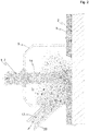
- eine Detailansicht eines Saugkopfs aus
Fig. 1 - Fig. 3
- eine Detailansicht eines Materialstroms aus
Fig. 2 -
Fig. 1 zeigt ein Fließschema einer Ausführungsform eines erfindungsgemäßen Verfahrens zum Druckluftstrahlen mit mindestens einem festen Strahlmittel, um mindestens eine Oberfläche 2 zu behandeln, insbesondere um die mindestens eine Oberfläche 2 von Verunreinigung 3 (vgl.Fig. 2 ) zu reinigen, wobei als das mindestens eine feste Strahlmittel mindestens ein Leichtstoffgranulat mit Leichtstoffgranulatpartikeln verwendet wird, wobei die Leichtstoffgranulatpartikel eine hohle und/oder schaumartige Struktur aufweisen. Im gezeigten Ausführungsbeispiel handelt es sich bei den Leichtstoffgranulatpartikeln um geschlossenzellig geblähte/expandierte Perlitsandpartikel 1. - Analog illustriert
Fig. 1 eine Ausführungsform einer erfindungsgemäßen Vorrichtung zum Druckluftstrahlen mit mindestens einem festen Strahlmittel, um die mindestens eine Oberfläche 2 zu behandeln, insbesondere um die mindestens eine Oberfläche 2 von Verunreinigung 3 zu reinigen, wobei die Vorrichtung zur Durchführung des erfindungsgemäßen Verfahrens eingerichtet ist. Bzw. illustriertFig. 1 eine Ausführungsform eines erfindungsgemäßen Systems umfassend die erfindungsgemäße Vorrichtung sowie das Leichtstoffgranulat mit geschlossenzellig expandierten Perlitsandpartikeln 1. - Die expandierten Perlitsandpartikel 1 werden aus einem Strahlmittelbehälter 12 einem Injektor 13 zugeführt. Im Injektor 13 werden die Perlitsandpartikel 1 Druckluft 7 beigemengt. Die Druckluft 7 wird mittels eines Kompressors 8 erzeugt, der Luft 18 aus der Umgebung ansaugt, und weist im dargestellten Ausführungsbeispiel einen Überdruck von lediglich ca. 3 bar auf.
- Aufgrund der geringen Dichte der Perlitsandpartikel 1 reicht dieser Überdruck aus, dass die Perlitsandpartikel 1 von der Druckluft 7 mitgerissen und in einer Zuleitung 19 zu einer Düse 14 transportiert werden. Im dargestellten Ausführungsbeispiel ist die Schüttdichte der expandierten Perlitsandpartikel 1 kleiner gleich 500 g/l.
- Aus der Düse 14 tritt nicht nur die Druckluft 7, sondern treten auch die Perlitsandpartikel 1 aus, wobei die Perlitsandpartikel 1 eine - vergleichsweise geringe - (Austritts-)Geschwindigkeit von ca. 110 m/s aufweisen. Die Perlitsandpartikel 1 treffen in weiterer Folge auf die von Verunreinigung 3 zu reinigende Oberfläche 2, wobei die Düse 14 auf die Oberfläche 2 gerichtet ist. Aufgrund des relativ geringen Abstands zwischen Düse 14 und Oberfläche 2 ist eine Auftreffgeschwindigkeit, mit der die Perlitsandpartikel 1 auf der Oberfläche 2 auftreffen nur unwesentlich geringer als die Austrittsgeschwindigkeit.
- Aufgrund der geringen Geschwindigkeit der Perlitsandpartikel 1 wird die Oberfläche 2 nicht geschädigt. Gleichzeitig kann aber trotzdem die Verunreinigung 3 abgetragen werden.
- Im gezeigten Ausführungsbeispiel weisen die Perlitsandpartikel 1 eine Korngröße kleiner gleich 600 µm auf, was sich für einen großen Bereich von Anwendungen als günstig erweist.
- Grundsätzlich kann je nach Anwendung bzw. je nach Empfindlichkeit der zu behandelnden Oberfläche 2, insbesondere auf Basis von Erfahrungswerten, eine optimale Kombination aus Schüttdichte und Korngröße/Körnung gewählt werden. In aufwendigen Versuchen konnten besonders gute Ergebnisse für die Reinigung von Oberflächen 2 auf Fassaden erzielt werden für eine Schüttdichte der Perlitsandpartikel 1 von ca. 150 g/l und eine Körnung von 150 µm bis 550 µm oder für eine Schüttdichte von ca. 200 g/l und eine Körnung von 100 µm bis 400 µm.
- Mit abnehmender Schüttdichte sinkt auch die Druckfestigkeit der Perlitsandpartikel 1. Im gezeigten Ausführungsbeispiel ist die Druckfestigkeit der Perlitsandpartikel 1 kleiner gleich 7 N/mm2. Dies stellt sicher, dass selbst bei höheren Geschwindigkeiten der Perlitsandpartikel 1 die Oberfläche 2 nicht beschädigt wird, da in diesem Fall beim Aufprall auf der Oberfläche 2 die kinetische Energie durch Zerstörung der Perlitsandpartikel 1 abgebaut wird.
- Im gezeigten Ausführungsbeispiel ist die Düse 14 in einem Saugkopf 9 angeordnet. Der Saugkopf 9 ist beim Druckluftstrahlen an die zu reinigende Oberfläche 2 herangeführt und kann diese mit einem Rand berühren, sodass ein Hohlraum durch den Saugkopf 9 und die Oberfläche 2 begrenzt wird, in welchem Hohlraum die Behandlung bzw. der Reinigungsvorgang stattfindet. Der Saugkopf 9 verhindert dabei zunächst, dass die Perlitsandpartikel 1 nach deren Aufprall an der Oberfläche 2 verlorengehen. Stattdessen werden diese "gebrauchten" Perlitsandpartikel 1 aus dem Saugkopf 9 durch eine in den Saugkopf 9 mündende Absaugleitung 20 mittels eines Ventilators 10 abgesaugt.
- Durch die auf die Oberfläche 2 auftreffenden Perlitsandpartikel 1 wird, wie gesagt, Verunreinigung 3 von der Oberfläche 2 entfernt bzw. abgetragen, sodass abgetragenes Material 22 entsteht. Dieses abgetragene Material 22 wird gemeinsam mit den "gebrauchten" Perlitsandpartikeln 1 abgesaugt. D.h. es wird ein Materialstrom 17 durch die Absaugleitung 20 abgesaugt, der neben Luft die "gebrauchten" Perlitsandpartikel 1 sowie das abgetragene Material 22 umfasst.
- In der Detailansicht der
Fig. 3 ist zu erkennen, dass der Materialstrom 17 nicht nur unzerstörte Perlitsandpartikel 1 enthält, sondern auch einen gewissen, typischerweise nicht völlig unvermeidlichen, Anteil an Perlitsandpartikeln 6, die beim Aufprall auf die Oberfläche 2 zerborsten sind und entsprechend sehr kleine, sehr leichte Partikel ausbilden, die typischerweise kein oder nur noch ein geringes Hohlraumvolumen einschließen. - Um unzerstörte Perlitsandpartikel 1 für eine weitere Verwendung beim Druckluftstrahlen wieder zu gewinnen, wird der Materialstrom 17 über die Absaugleitung 20 zunächst einem Fliehkraftabscheider in Form eines Zyklons 4 zugeführt. Auf der Reingasseite des Zyklons 4 entweicht Abluft 21 samt den zerborstenen Perlitsandpartikeln 6, wobei letztere in einem dem Zyklon 4 nachgeschalteten Filter 5 abgeschieden werden und anschließend in einen Abfallbehälter 15 gelangen.
- Aufgrund ihrer Masse trennt der Zyklon 4 die unzerstörten Perlitsandpartikel 1 und das abgetragene Material 22 von der Abluft 21 samt den zerborstenen Perlitsandpartikeln 6. Mittels eines nachgeschalteten Siebs 11 findet eine Trennung der unzerstörten Perlitsandpartikel 1 vom typischerweise deutlich größeren abgetragenen Material 22 statt. Das abgetragene Material 22 wird sodann ebenfalls dem Abfallbehälter 15 zugeführt.
- Die unzerstörten Perlitsandpartikel 1 stehen hingegen für eine erneute Zuführung zum Injektor 13 bereit und gelangen in den Strahlmittelbehälter 12, der den Injektor 13 mit Perlitsandpartikeln 1 versorgt.
- Um sicherzustellen, dass der Injektor 13 stets mit hinreichend vielen Perlitsandpartikeln 1 versorgt wird, ist weiters ein Behälter 16 mit frischem geblähten Perlitsand vorgesehen. Auch aus diesem Behälter 16 können dem Strahlmittelbehälter 12 bei Bedarf Perlitsandpartikel 1 zugeführt werden.
-
- 1
- Geblähte Perlitsandpartikel
- 2
- Oberfläche
- 3
- Verunreinigung
- 4
- Zyklon
- 5
- Filter
- 6
- Zerborstene Perlitsandpartikel
- 7
- Druckluft
- 8
- Kompressor
- 9
- Saugkopf
- 10
- Ventilator
- 11
- Sieb
- 12
- Strahlmittelbehälter
- 13
- Injektor
- 14
- Düse
- 15
- Abfallbehälter
- 16
- Behälter mit frischem geblähten Perlitsand
- 17
- Materialstrom
- 18
- Angesaugte Luft
- 19
- Zuleitung
- 20
- Absaugleitung
- 21
- Abluft
- 22
- Abgetragenes Material
Claims (15)
- Verfahren zum Druckluftstrahlen mit mindestens einem festen Strahlmittel, um mindestens eine Oberfläche (2) zu behandeln, insbesondere um die mindestens eine Oberfläche (2) von Verunreinigung (3) zu reinigen, dadurch gekennzeichnet, dass als das mindestens eine feste Strahlmittel mindestens ein Leichtstoffgranulat mit Leichtstoffgranulatpartikeln (1) verwendet wird, wobei die Leichtstoffgranulatpartikel (1) eine hohle und/oder schaumartige Struktur aufweisen.
- Verfahren nach Anspruch 1, dadurch gekennzeichnet, dass das mindestens eine Leichtstoffgranulat mindestens einen expandierten, insbesondere geschlossenzellig expandierten, Perlitsand (1) und/oder mindestens ein Blähglas und/oder mindestens ein Glasschaumgranulat und/oder Flugasche-Cenosphären und/oder synthetische Glashohlkugeln umfasst.
- Verfahren nach einem der Ansprüche 1 bis 2, dadurch gekennzeichnet, dass die Leichtstoffgranulatpartikel (1) eine Korngröße von kleiner gleich 600 µm, bevorzugt eine Korngröße im Bereich von 100 µm bis 550 µm, besonders bevorzugt eine Korngröße im Bereich von 100 µm bis 400 µm, aufweisen.
- Verfahren nach einem der Ansprüche 1 bis 3, dadurch gekennzeichnet, dass das Leichtstoffgranulat eine Schüttdichte von kleiner gleich 500 g/l, bevorzugt im Bereich von 30 g/l bis 300 g/l, besonders bevorzugt im Bereich von 150 g/l bis 200 g/l, aufweist.
- Verfahren nach einem der Ansprüche 1 bis 4, dadurch gekennzeichnet, dass das Leichtstoffgranulat eine Druckfestigkeit von kleiner gleich 7 N/mm2 aufweist.
- Verfahren nach einem der Ansprüche 1 bis 5, dadurch gekennzeichnet, dass Druckluft (7) mit einem Überdruck im Bereich von 2 bar bis 4 bar, vorzugsweise von 2,5 bar bis 3,5 bar, verwendet wird.
- Verfahren nach einem der Ansprüche 1 bis 6, dadurch gekennzeichnet, dass die Leichtstoffgranulatpartikel (1) eine Geschwindigkeit im Bereich von 90 m/s bis 130 m/s, vorzugsweise von 99 m/s bis 121 m/s, aufweisen.
- Verfahren nach einem der Ansprüche 1 bis 7, dadurch gekennzeichnet, dass zumindest die Leichtstoffgranulatpartikel (1) nach deren Auftreffen auf der mindestens einen Oberfläche (2) abgesaugt und recycelt werden.
- Verfahren nach Anspruch 8, dadurch gekennzeichnet, dass das Recyceln mittels mindestens eines Zyklons (4) erfolgt, wobei zerborstene Leichtstoffgranulatpartikel (6) mittels mindestens eines nachgeschalteten Filters (5) als Abfall abgeschieden werden.
- Vorrichtung zum Druckluftstrahlen mit mindestens einem festen Strahlmittel, um mindestens eine Oberfläche (2) zu behandeln, insbesondere um die mindestens eine Oberfläche (2) von Verunreinigung (3) zu reinigen, dadurch gekennzeichnet, dass die Vorrichtung zur Durchführung eines Verfahrens nach einem der Ansprüche 1 bis 9 eingerichtet ist.
- Vorrichtung nach Anspruch 10, dadurch gekennzeichnet, dass mindestens ein Überdruckmittel, insbesondere mindestens ein Kompressor (8), zur Bereitstellung von Druckluft (7) mit einem Überdruck im Bereich von 2 bar bis 4 bar, vorzugsweise von 2,5 bar bis 3,5 bar, vorgesehen ist, um mit der Druckluft die Leichtstoffgranulatpartikel (1) auf eine Geschwindigkeit im Bereich von 90 m/s bis 130 m/s, vorzugsweise von 99 m/s bis 121 m/s, zu beschleunigen.
- Vorrichtung nach einem der Ansprüche 10 bis 11, dadurch gekennzeichnet, dass mindestens ein Saugkopf (9) vorgesehen ist, um zumindest die Leichtstoffgranulatpartikel (1) nach deren Auftreffen auf der mindestens einen Oberfläche (2) abzusaugen.
- Vorrichtung nach Anspruch 12, dadurch gekennzeichnet, dass mindestens ein dem mindestens einen Saugkopf (9) nachgeschalteter Zyklon (4) und mindestens ein dem mindestens einen Zyklon (4) nachgeschalteter Filter (5) vorgesehen sind, um die Leichtstoffgranulatpartikel (1) zu recyceln und zerborstene Leichtstoffgranulatpartikel (6) als Abfall abzuscheiden.
- System umfassend die Vorrichtung nach einem der Ansprüche 10 bis 13 sowie das mindestens eine Leichtstoffgranulat.
- System nach Anspruch 14, dadurch gekennzeichnet, dass das mindestens eine Leichtstoffgranulat mindestens einen expandierten, insbesondere geschlossenzellig expandierten, Perlitsand (1) und/oder mindestens ein Blähglas und/oder mindestens ein Glasschaumgranulat und/oder Flugasche-Cenosphären und/oder synthetische Glashohlkugeln umfasst.
Priority Applications (7)
| Application Number | Priority Date | Filing Date | Title |
|---|---|---|---|
| HRP20240011TT HRP20240011T1 (hr) | 2020-05-20 | 2020-05-20 | Postupak pjeskarenja čvrstim sredstvom za pjeskarenje |
| PL20175859.6T PL3912760T3 (pl) | 2020-05-20 | 2020-05-20 | Sposób pneumatycznej obróbki strumieniowo-ściernej z użyciem stałego materiału ściernego |
| DK20175859.6T DK3912760T3 (da) | 2020-05-20 | 2020-05-20 | Fremgangsmåde til trykluftblæsning med fast blæsemiddel |
| EP20175859.6A EP3912760B1 (de) | 2020-05-20 | 2020-05-20 | Verfahren zum druckluftstrahlen mit festem strahlmittel |
| ES20175859T ES2969079T3 (es) | 2020-05-20 | 2020-05-20 | Procedimiento para el chorreado con aire comprimido con medio de chorreado sólido |
| HUE20175859A HUE065115T2 (hu) | 2020-05-20 | 2020-05-20 | Sûrített levegõs szórási eljárás szilárd szóróanyaggal |
| FIEP20175859.6T FI3912760T3 (fi) | 2020-05-20 | 2020-05-20 | Menetelmä paineilmapuhallusta varten kiinteällä puhallusaineella |
Applications Claiming Priority (1)
| Application Number | Priority Date | Filing Date | Title |
|---|---|---|---|
| EP20175859.6A EP3912760B1 (de) | 2020-05-20 | 2020-05-20 | Verfahren zum druckluftstrahlen mit festem strahlmittel |
Publications (2)
| Publication Number | Publication Date |
|---|---|
| EP3912760A1 true EP3912760A1 (de) | 2021-11-24 |
| EP3912760B1 EP3912760B1 (de) | 2023-11-15 |
Family
ID=70802719
Family Applications (1)
| Application Number | Title | Priority Date | Filing Date |
|---|---|---|---|
| EP20175859.6A Active EP3912760B1 (de) | 2020-05-20 | 2020-05-20 | Verfahren zum druckluftstrahlen mit festem strahlmittel |
Country Status (7)
| Country | Link |
|---|---|
| EP (1) | EP3912760B1 (de) |
| DK (1) | DK3912760T3 (de) |
| ES (1) | ES2969079T3 (de) |
| FI (1) | FI3912760T3 (de) |
| HR (1) | HRP20240011T1 (de) |
| HU (1) | HUE065115T2 (de) |
| PL (1) | PL3912760T3 (de) |
Cited By (1)
| Publication number | Priority date | Publication date | Assignee | Title |
|---|---|---|---|---|
| US20230415237A1 (en) * | 2022-06-22 | 2023-12-28 | Desktop Metal, Inc. | Shot Brush Depowdering |
Citations (7)
| Publication number | Priority date | Publication date | Assignee | Title |
|---|---|---|---|---|
| RU1794416C (ru) * | 1990-05-03 | 1993-02-15 | Государственный Научно-Исследовательский И Проектный Институт Силикатного Бетона | Субстрат дл выращивани растений |
| DE10102924C1 (de) * | 2001-01-23 | 2002-06-13 | Pieper Innovationsgmbh | Verfahren und Vorrichtung zum Strahlbearbeiten, insbesondere formgenauen Abtragen und/oder Verdichten und/oder Beschichten, von festen Flächen |
| US20070042676A1 (en) * | 2005-08-17 | 2007-02-22 | Hitachi Plant Technologies, Ltd. | Blasting apparatus and blasting method |
| US20130029563A1 (en) * | 2010-04-15 | 2013-01-31 | Kompoferm Gmbh | Blasting agent and blasting method |
| EP2697181B1 (de) | 2011-10-10 | 2015-07-22 | Binder+Co AG | Verfahren zum geschlossenzelligen blähen von mineralischem material |
| EP2708517B1 (de) | 2012-09-13 | 2017-06-28 | Binder + Co Aktiengesellschaft | Verfahren zur herstellung von blähglas |
| US20170259401A1 (en) * | 2014-12-08 | 2017-09-14 | Sintokogio, Ltd. | Polishing device and polishing method |
-
2020
- 2020-05-20 HR HRP20240011TT patent/HRP20240011T1/hr unknown
- 2020-05-20 PL PL20175859.6T patent/PL3912760T3/pl unknown
- 2020-05-20 HU HUE20175859A patent/HUE065115T2/hu unknown
- 2020-05-20 ES ES20175859T patent/ES2969079T3/es active Active
- 2020-05-20 FI FIEP20175859.6T patent/FI3912760T3/fi active
- 2020-05-20 DK DK20175859.6T patent/DK3912760T3/da active
- 2020-05-20 EP EP20175859.6A patent/EP3912760B1/de active Active
Patent Citations (7)
| Publication number | Priority date | Publication date | Assignee | Title |
|---|---|---|---|---|
| RU1794416C (ru) * | 1990-05-03 | 1993-02-15 | Государственный Научно-Исследовательский И Проектный Институт Силикатного Бетона | Субстрат дл выращивани растений |
| DE10102924C1 (de) * | 2001-01-23 | 2002-06-13 | Pieper Innovationsgmbh | Verfahren und Vorrichtung zum Strahlbearbeiten, insbesondere formgenauen Abtragen und/oder Verdichten und/oder Beschichten, von festen Flächen |
| US20070042676A1 (en) * | 2005-08-17 | 2007-02-22 | Hitachi Plant Technologies, Ltd. | Blasting apparatus and blasting method |
| US20130029563A1 (en) * | 2010-04-15 | 2013-01-31 | Kompoferm Gmbh | Blasting agent and blasting method |
| EP2697181B1 (de) | 2011-10-10 | 2015-07-22 | Binder+Co AG | Verfahren zum geschlossenzelligen blähen von mineralischem material |
| EP2708517B1 (de) | 2012-09-13 | 2017-06-28 | Binder + Co Aktiengesellschaft | Verfahren zur herstellung von blähglas |
| US20170259401A1 (en) * | 2014-12-08 | 2017-09-14 | Sintokogio, Ltd. | Polishing device and polishing method |
Cited By (1)
| Publication number | Priority date | Publication date | Assignee | Title |
|---|---|---|---|---|
| US20230415237A1 (en) * | 2022-06-22 | 2023-12-28 | Desktop Metal, Inc. | Shot Brush Depowdering |
Also Published As
| Publication number | Publication date |
|---|---|
| PL3912760T3 (pl) | 2024-04-15 |
| EP3912760B1 (de) | 2023-11-15 |
| FI3912760T3 (fi) | 2024-01-10 |
| DK3912760T3 (da) | 2024-01-15 |
| HUE065115T2 (hu) | 2024-05-28 |
| ES2969079T3 (es) | 2024-05-16 |
| HRP20240011T1 (hr) | 2024-03-29 |
Similar Documents
| Publication | Publication Date | Title |
|---|---|---|
| EP3733307B1 (de) | Verfahren und vorrichtung zur erzeugung einer dekorativen oberfläche | |
| EP0171448B1 (de) | Vorrichtung und Verfahren zum Reinigen von Stein- und Metalloberflächen | |
| EP0343272B1 (de) | Verfahren und Vorrichtung zum Regenieren von Giessereialtsanden | |
| DE2756786A1 (de) | Oberflaechen-behandlungsgeraet | |
| EP1486642A2 (de) | Entstauber mit Mehrstrahldüsen | |
| EP0316264B1 (de) | Verfahren und Vorrichtung zum Entlacken und Entfernen von Schichten von Flächen | |
| EP2913149B1 (de) | Strahlverfahren und -vorrichtung | |
| EP3912760B1 (de) | Verfahren zum druckluftstrahlen mit festem strahlmittel | |
| EP2230005A1 (de) | Betriebssichere Beschichtungsvorrichtung für pulverförmiges Material | |
| DE3505675A1 (de) | Verfahren zum abtragen von oberflaechen | |
| EP3431656B1 (de) | Verfahren zur behandlung von schottersteinen | |
| EP2542327B1 (de) | Verfahren zum reinigen von filtern | |
| DE102017007801A1 (de) | Verfahren und Vorrichtung zum Verfestigungsstrahlen oder Verfestigungswalzen | |
| EP0962263B1 (de) | Verfahren und Anlage zur Entfernung von gefährdenden Beschichtungen | |
| DE102004014387B4 (de) | Reinigungsverfahren für Magnetische Fremdkörper auf der Oberfläche von Gegenständen | |
| DE102019219919A1 (de) | Vorrichtung zur Entnahme und Dosierung von Strahlgut | |
| DE102010043285A1 (de) | Verfahren, Strahlmittel und Vorrichtung zum Behandeln eines Bauelements | |
| EP0649944B1 (de) | Vorrichtung zur Beseitigung unerwünschten Pflanzenwuchses auf befestigten Flächen | |
| EP2025485A1 (de) | Faserzementprodukt | |
| DE102014114868A1 (de) | Vorrichtung und Verfahren zum Abstrahlen eines Reinigungsmediums auf eine zu reinigende Fläche | |
| DE202014105123U1 (de) | Vorrichtung zur Zerkleinerung von Faserverbundwerkstoffen | |
| WO2002070202A2 (de) | Strahlverfahren zum reinigen von rohren | |
| EP1882778A2 (de) | Verfahren und Vorrichtung zum Reinigen von Straßen | |
| DE2823578A1 (de) | Verfahren und vorrichtung zur regenerierung von giessereialtsand | |
| DE19603502A1 (de) | Verfahren und Vorrichtung zur Behandlung von Beton-Formsteinen |
Legal Events
| Date | Code | Title | Description |
|---|---|---|---|
| REG | Reference to a national code |
Ref country code: HR Ref legal event code: TUEP Ref document number: P20240011T Country of ref document: HR |
|
| PUAI | Public reference made under article 153(3) epc to a published international application that has entered the european phase |
Free format text: ORIGINAL CODE: 0009012 |
|
| STAA | Information on the status of an ep patent application or granted ep patent |
Free format text: STATUS: THE APPLICATION HAS BEEN PUBLISHED |
|
| AK | Designated contracting states |
Kind code of ref document: A1 Designated state(s): AL AT BE BG CH CY CZ DE DK EE ES FI FR GB GR HR HU IE IS IT LI LT LU LV MC MK MT NL NO PL PT RO RS SE SI SK SM TR |
|
| B565 | Issuance of search results under rule 164(2) epc |
Effective date: 20201023 |
|
| STAA | Information on the status of an ep patent application or granted ep patent |
Free format text: STATUS: REQUEST FOR EXAMINATION WAS MADE |
|
| 17P | Request for examination filed |
Effective date: 20220524 |
|
| RBV | Designated contracting states (corrected) |
Designated state(s): AL AT BE BG CH CY CZ DE DK EE ES FI FR GB GR HR HU IE IS IT LI LT LU LV MC MK MT NL NO PL PT RO RS SE SI SK SM TR |
|
| REG | Reference to a national code |
Ref country code: DE Ref legal event code: R079 Free format text: PREVIOUS MAIN CLASS: B24C0003320000 Ipc: B24C0003060000 Ref country code: DE Ref legal event code: R079 Ref document number: 502020006002 Country of ref document: DE Free format text: PREVIOUS MAIN CLASS: B24C0003320000 Ipc: B24C0003060000 |
|
| GRAP | Despatch of communication of intention to grant a patent |
Free format text: ORIGINAL CODE: EPIDOSNIGR1 |
|
| STAA | Information on the status of an ep patent application or granted ep patent |
Free format text: STATUS: GRANT OF PATENT IS INTENDED |
|
| RIC1 | Information provided on ipc code assigned before grant |
Ipc: B24C 11/00 20060101ALI20230602BHEP Ipc: B24C 9/00 20060101ALI20230602BHEP Ipc: B24C 7/00 20060101ALI20230602BHEP Ipc: B24C 3/06 20060101AFI20230602BHEP |
|
| INTG | Intention to grant announced |
Effective date: 20230712 |
|
| GRAS | Grant fee paid |
Free format text: ORIGINAL CODE: EPIDOSNIGR3 |
|
| RAP1 | Party data changed (applicant data changed or rights of an application transferred) |
Owner name: OMYA INTERNATIONAL AG |
|
| GRAA | (expected) grant |
Free format text: ORIGINAL CODE: 0009210 |
|
| STAA | Information on the status of an ep patent application or granted ep patent |
Free format text: STATUS: THE PATENT HAS BEEN GRANTED |
|
| P01 | Opt-out of the competence of the unified patent court (upc) registered |
Effective date: 20231004 |
|
| AK | Designated contracting states |
Kind code of ref document: B1 Designated state(s): AL AT BE BG CH CY CZ DE DK EE ES FI FR GB GR HR HU IE IS IT LI LT LU LV MC MK MT NL NO PL PT RO RS SE SI SK SM TR |
|
| REG | Reference to a national code |
Ref country code: CH Ref legal event code: EP Ref country code: GB Ref legal event code: FG4D Free format text: NOT ENGLISH |
|
| REG | Reference to a national code |
Ref country code: DE Ref legal event code: R096 Ref document number: 502020006002 Country of ref document: DE |
|
| REG | Reference to a national code |
Ref country code: IE Ref legal event code: FG4D Free format text: LANGUAGE OF EP DOCUMENT: GERMAN |
|
| REG | Reference to a national code |
Ref country code: FI Ref legal event code: FGE |
|
| REG | Reference to a national code |
Ref country code: DK Ref legal event code: T3 Effective date: 20240110 |
|
| REG | Reference to a national code |
Ref country code: NL Ref legal event code: FP |
|
| REG | Reference to a national code |
Ref country code: SE Ref legal event code: TRGR |
|
| REG | Reference to a national code |
Ref country code: GR Ref legal event code: EP Ref document number: 20240400087 Country of ref document: GR Effective date: 20240209 Ref country code: SK Ref legal event code: T3 Ref document number: E 43206 Country of ref document: SK |
|
| REG | Reference to a national code |
Ref country code: LT Ref legal event code: MG9D |
|
| REG | Reference to a national code |
Ref country code: HR Ref legal event code: T1PR Ref document number: P20240011 Country of ref document: HR |
|
| PG25 | Lapsed in a contracting state [announced via postgrant information from national office to epo] |
Ref country code: IS Free format text: LAPSE BECAUSE OF FAILURE TO SUBMIT A TRANSLATION OF THE DESCRIPTION OR TO PAY THE FEE WITHIN THE PRESCRIBED TIME-LIMIT Effective date: 20240315 |
|
| PG25 | Lapsed in a contracting state [announced via postgrant information from national office to epo] |
Ref country code: LT Free format text: LAPSE BECAUSE OF FAILURE TO SUBMIT A TRANSLATION OF THE DESCRIPTION OR TO PAY THE FEE WITHIN THE PRESCRIBED TIME-LIMIT Effective date: 20231115 |
|
| PG25 | Lapsed in a contracting state [announced via postgrant information from national office to epo] |
Ref country code: LT Free format text: LAPSE BECAUSE OF FAILURE TO SUBMIT A TRANSLATION OF THE DESCRIPTION OR TO PAY THE FEE WITHIN THE PRESCRIBED TIME-LIMIT Effective date: 20231115 Ref country code: IS Free format text: LAPSE BECAUSE OF FAILURE TO SUBMIT A TRANSLATION OF THE DESCRIPTION OR TO PAY THE FEE WITHIN THE PRESCRIBED TIME-LIMIT Effective date: 20240315 Ref country code: BG Free format text: LAPSE BECAUSE OF FAILURE TO SUBMIT A TRANSLATION OF THE DESCRIPTION OR TO PAY THE FEE WITHIN THE PRESCRIBED TIME-LIMIT Effective date: 20240215 Ref country code: PT Free format text: LAPSE BECAUSE OF FAILURE TO SUBMIT A TRANSLATION OF THE DESCRIPTION OR TO PAY THE FEE WITHIN THE PRESCRIBED TIME-LIMIT Effective date: 20240315 |
|
| REG | Reference to a national code |
Ref country code: ES Ref legal event code: FG2A Ref document number: 2969079 Country of ref document: ES Kind code of ref document: T3 Effective date: 20240516 |
|
| REG | Reference to a national code |
Ref country code: HR Ref legal event code: ODRP Ref document number: P20240011 Country of ref document: HR Payment date: 20240510 Year of fee payment: 5 |
|
| REG | Reference to a national code |
Ref country code: HU Ref legal event code: AG4A Ref document number: E065115 Country of ref document: HU |
|
| PG25 | Lapsed in a contracting state [announced via postgrant information from national office to epo] |
Ref country code: RS Free format text: LAPSE BECAUSE OF FAILURE TO SUBMIT A TRANSLATION OF THE DESCRIPTION OR TO PAY THE FEE WITHIN THE PRESCRIBED TIME-LIMIT Effective date: 20231115 Ref country code: NO Free format text: LAPSE BECAUSE OF FAILURE TO SUBMIT A TRANSLATION OF THE DESCRIPTION OR TO PAY THE FEE WITHIN THE PRESCRIBED TIME-LIMIT Effective date: 20240215 Ref country code: LV Free format text: LAPSE BECAUSE OF FAILURE TO SUBMIT A TRANSLATION OF THE DESCRIPTION OR TO PAY THE FEE WITHIN THE PRESCRIBED TIME-LIMIT Effective date: 20231115 |
|
| PG25 | Lapsed in a contracting state [announced via postgrant information from national office to epo] |
Ref country code: SM Free format text: LAPSE BECAUSE OF FAILURE TO SUBMIT A TRANSLATION OF THE DESCRIPTION OR TO PAY THE FEE WITHIN THE PRESCRIBED TIME-LIMIT Effective date: 20231115 Ref country code: RO Free format text: LAPSE BECAUSE OF FAILURE TO SUBMIT A TRANSLATION OF THE DESCRIPTION OR TO PAY THE FEE WITHIN THE PRESCRIBED TIME-LIMIT Effective date: 20231115 Ref country code: EE Free format text: LAPSE BECAUSE OF FAILURE TO SUBMIT A TRANSLATION OF THE DESCRIPTION OR TO PAY THE FEE WITHIN THE PRESCRIBED TIME-LIMIT Effective date: 20231115 |
|
| REG | Reference to a national code |
Ref country code: DE Ref legal event code: R097 Ref document number: 502020006002 Country of ref document: DE |
|
| PLBE | No opposition filed within time limit |
Free format text: ORIGINAL CODE: 0009261 |
|
| STAA | Information on the status of an ep patent application or granted ep patent |
Free format text: STATUS: NO OPPOSITION FILED WITHIN TIME LIMIT |
|
| 26N | No opposition filed |
Effective date: 20240819 |
|
| PG25 | Lapsed in a contracting state [announced via postgrant information from national office to epo] |
Ref country code: SI Free format text: LAPSE BECAUSE OF FAILURE TO SUBMIT A TRANSLATION OF THE DESCRIPTION OR TO PAY THE FEE WITHIN THE PRESCRIBED TIME-LIMIT Effective date: 20231115 |
|
| PG25 | Lapsed in a contracting state [announced via postgrant information from national office to epo] |
Ref country code: SI Free format text: LAPSE BECAUSE OF FAILURE TO SUBMIT A TRANSLATION OF THE DESCRIPTION OR TO PAY THE FEE WITHIN THE PRESCRIBED TIME-LIMIT Effective date: 20231115 |
|
| PG25 | Lapsed in a contracting state [announced via postgrant information from national office to epo] |
Ref country code: MC Free format text: LAPSE BECAUSE OF FAILURE TO SUBMIT A TRANSLATION OF THE DESCRIPTION OR TO PAY THE FEE WITHIN THE PRESCRIBED TIME-LIMIT Effective date: 20231115 |
|
| PG25 | Lapsed in a contracting state [announced via postgrant information from national office to epo] |
Ref country code: LU Free format text: LAPSE BECAUSE OF NON-PAYMENT OF DUE FEES Effective date: 20240520 |
|
| PG25 | Lapsed in a contracting state [announced via postgrant information from national office to epo] |
Ref country code: MC Free format text: LAPSE BECAUSE OF FAILURE TO SUBMIT A TRANSLATION OF THE DESCRIPTION OR TO PAY THE FEE WITHIN THE PRESCRIBED TIME-LIMIT Effective date: 20231115 Ref country code: LU Free format text: LAPSE BECAUSE OF NON-PAYMENT OF DUE FEES Effective date: 20240520 |
|
| PG25 | Lapsed in a contracting state [announced via postgrant information from national office to epo] |
Ref country code: IE Free format text: LAPSE BECAUSE OF NON-PAYMENT OF DUE FEES Effective date: 20240520 |
|
| REG | Reference to a national code |
Ref country code: HR Ref legal event code: ODRP Ref document number: P20240011 Country of ref document: HR Payment date: 20250508 Year of fee payment: 6 |
|
| PGFP | Annual fee paid to national office [announced via postgrant information from national office to epo] |
Ref country code: NL Payment date: 20250521 Year of fee payment: 6 |
|
| PGFP | Annual fee paid to national office [announced via postgrant information from national office to epo] |
Ref country code: FI Payment date: 20250526 Year of fee payment: 6 |
|
| PGFP | Annual fee paid to national office [announced via postgrant information from national office to epo] |
Ref country code: PL Payment date: 20250513 Year of fee payment: 6 Ref country code: DE Payment date: 20250521 Year of fee payment: 6 |
|
| PGFP | Annual fee paid to national office [announced via postgrant information from national office to epo] |
Ref country code: GB Payment date: 20250527 Year of fee payment: 6 Ref country code: DK Payment date: 20250526 Year of fee payment: 6 |
|
| PGFP | Annual fee paid to national office [announced via postgrant information from national office to epo] |
Ref country code: HU Payment date: 20250523 Year of fee payment: 6 |
|
| PGFP | Annual fee paid to national office [announced via postgrant information from national office to epo] |
Ref country code: IT Payment date: 20250527 Year of fee payment: 6 Ref country code: BE Payment date: 20250521 Year of fee payment: 6 |
|
| PGFP | Annual fee paid to national office [announced via postgrant information from national office to epo] |
Ref country code: HR Payment date: 20250508 Year of fee payment: 6 |
|
| PGFP | Annual fee paid to national office [announced via postgrant information from national office to epo] |
Ref country code: FR Payment date: 20250528 Year of fee payment: 6 |
|
| PGFP | Annual fee paid to national office [announced via postgrant information from national office to epo] |
Ref country code: GR Payment date: 20250523 Year of fee payment: 6 |
|
| PGFP | Annual fee paid to national office [announced via postgrant information from national office to epo] |
Ref country code: CH Payment date: 20250601 Year of fee payment: 6 |
|
| PGFP | Annual fee paid to national office [announced via postgrant information from national office to epo] |
Ref country code: AT Payment date: 20250522 Year of fee payment: 6 |
|
| PGFP | Annual fee paid to national office [announced via postgrant information from national office to epo] |
Ref country code: TR Payment date: 20250513 Year of fee payment: 6 Ref country code: SK Payment date: 20250512 Year of fee payment: 6 |
|
| PGFP | Annual fee paid to national office [announced via postgrant information from national office to epo] |
Ref country code: CZ Payment date: 20250514 Year of fee payment: 6 |
|
| PGFP | Annual fee paid to national office [announced via postgrant information from national office to epo] |
Ref country code: SE Payment date: 20250521 Year of fee payment: 6 |
|
| PG25 | Lapsed in a contracting state [announced via postgrant information from national office to epo] |
Ref country code: CY Free format text: LAPSE BECAUSE OF FAILURE TO SUBMIT A TRANSLATION OF THE DESCRIPTION OR TO PAY THE FEE WITHIN THE PRESCRIBED TIME-LIMIT; INVALID AB INITIO Effective date: 20200520 |
|
| PGFP | Annual fee paid to national office [announced via postgrant information from national office to epo] |
Ref country code: ES Payment date: 20250630 Year of fee payment: 6 |