EP3911983B1 - Method of fabricating a symmetric light guide optical element - Google Patents
Method of fabricating a symmetric light guide optical element Download PDFInfo
- Publication number
- EP3911983B1 EP3911983B1 EP20741433.5A EP20741433A EP3911983B1 EP 3911983 B1 EP3911983 B1 EP 3911983B1 EP 20741433 A EP20741433 A EP 20741433A EP 3911983 B1 EP3911983 B1 EP 3911983B1
- Authority
- EP
- European Patent Office
- Prior art keywords
- plates
- stack
- base block
- loe
- parallel
- Prior art date
- Legal status (The legal status is an assumption and is not a legal conclusion. Google has not performed a legal analysis and makes no representation as to the accuracy of the status listed.)
- Active
Links
Images



Classifications
-
- G—PHYSICS
- G02—OPTICS
- G02B—OPTICAL ELEMENTS, SYSTEMS OR APPARATUS
- G02B27/00—Optical systems or apparatus not provided for by any of the groups G02B1/00 - G02B26/00, G02B30/00
- G02B27/01—Head-up displays
-
- G—PHYSICS
- G02—OPTICS
- G02B—OPTICAL ELEMENTS, SYSTEMS OR APPARATUS
- G02B27/00—Optical systems or apparatus not provided for by any of the groups G02B1/00 - G02B26/00, G02B30/00
- G02B27/01—Head-up displays
- G02B27/017—Head mounted
- G02B27/0172—Head mounted characterised by optical features
-
- G—PHYSICS
- G02—OPTICS
- G02B—OPTICAL ELEMENTS, SYSTEMS OR APPARATUS
- G02B27/00—Optical systems or apparatus not provided for by any of the groups G02B1/00 - G02B26/00, G02B30/00
- G02B27/0081—Optical systems or apparatus not provided for by any of the groups G02B1/00 - G02B26/00, G02B30/00 with means for altering, e.g. enlarging, the entrance or exit pupil
-
- G—PHYSICS
- G02—OPTICS
- G02B—OPTICAL ELEMENTS, SYSTEMS OR APPARATUS
- G02B27/00—Optical systems or apparatus not provided for by any of the groups G02B1/00 - G02B26/00, G02B30/00
- G02B27/10—Beam splitting or combining systems
- G02B27/1073—Beam splitting or combining systems characterized by manufacturing or alignment methods
-
- G—PHYSICS
- G02—OPTICS
- G02B—OPTICAL ELEMENTS, SYSTEMS OR APPARATUS
- G02B27/00—Optical systems or apparatus not provided for by any of the groups G02B1/00 - G02B26/00, G02B30/00
- G02B27/10—Beam splitting or combining systems
- G02B27/14—Beam splitting or combining systems operating by reflection only
- G02B27/145—Beam splitting or combining systems operating by reflection only having sequential partially reflecting surfaces
-
- G—PHYSICS
- G02—OPTICS
- G02B—OPTICAL ELEMENTS, SYSTEMS OR APPARATUS
- G02B27/00—Optical systems or apparatus not provided for by any of the groups G02B1/00 - G02B26/00, G02B30/00
- G02B27/28—Optical systems or apparatus not provided for by any of the groups G02B1/00 - G02B26/00, G02B30/00 for polarising
- G02B27/283—Optical systems or apparatus not provided for by any of the groups G02B1/00 - G02B26/00, G02B30/00 for polarising used for beam splitting or combining
- G02B27/285—Optical systems or apparatus not provided for by any of the groups G02B1/00 - G02B26/00, G02B30/00 for polarising used for beam splitting or combining comprising arrays of elements, e.g. microprisms
-
- G—PHYSICS
- G02—OPTICS
- G02B—OPTICAL ELEMENTS, SYSTEMS OR APPARATUS
- G02B6/00—Light guides; Structural details of arrangements comprising light guides and other optical elements, e.g. couplings
- G02B6/10—Light guides; Structural details of arrangements comprising light guides and other optical elements, e.g. couplings of the optical waveguide type
- G02B6/12—Light guides; Structural details of arrangements comprising light guides and other optical elements, e.g. couplings of the optical waveguide type of the integrated circuit kind
- G02B6/13—Integrated optical circuits characterised by the manufacturing method
-
- G—PHYSICS
- G02—OPTICS
- G02B—OPTICAL ELEMENTS, SYSTEMS OR APPARATUS
- G02B27/00—Optical systems or apparatus not provided for by any of the groups G02B1/00 - G02B26/00, G02B30/00
- G02B27/01—Head-up displays
- G02B27/0101—Head-up displays characterised by optical features
- G02B2027/0118—Head-up displays characterised by optical features comprising devices for improving the contrast of the display / brillance control visibility
-
- G—PHYSICS
- G02—OPTICS
- G02B—OPTICAL ELEMENTS, SYSTEMS OR APPARATUS
- G02B27/00—Optical systems or apparatus not provided for by any of the groups G02B1/00 - G02B26/00, G02B30/00
- G02B27/01—Head-up displays
- G02B27/0101—Head-up displays characterised by optical features
- G02B2027/0118—Head-up displays characterised by optical features comprising devices for improving the contrast of the display / brillance control visibility
- G02B2027/012—Head-up displays characterised by optical features comprising devices for improving the contrast of the display / brillance control visibility comprising devices for attenuating parasitic image effects
Definitions
- the presently disclosed subject matter relates to methods of fabricating a symmetric light guide optical element (LOE) and, more particularly, to a symmetric LOE without a bonding interface.
- LOE symmetric light guide optical element
- HMD head-mounted displays
- an optical module serves as both an imaging lens and a combiner, whereby a two dimensional display is imaged to infinity and reflected into the eye of an observer.
- the display can be obtained directly from either a spatial light modulator (SLM) such as a cathode ray tube (CRT), a liquid crystal display (LCD), an organic light emitting diode array (OLED), a scanning source or similar devices, or indirectly, by means of a relay lens or an optical fiber bundle.
- SLM spatial light modulator
- CTR cathode ray tube
- LCD liquid crystal display
- OLED organic light emitting diode array
- scanning source or similar devices
- the display comprises an array of elements (pixels) imaged to infinity by a collimating lens and transmitted into the eye of the viewer by means of a reflecting, or partially reflecting, surface acting as a combiner for non-see through or see-through applications, respectively.
- a conventional, free-space optical module is used for this purpose.
- FOV field-of-view
- the strive for compactness has led to several different complex optical solutions, all of which, on one hand, are still not sufficiently compact for most practical applications, and on the other hand, are difficult to manufacture.
- the eye-motion-box (EMB) of the optical viewing angles resulting from these designs is usually very small-typically less than 8 mm.
- EMB eye-motion-box
- the performance of the optical systems are very sensitive even to small movements relative to the eye of the viewer, and do not allow sufficient pupil motion for convenient reading of a displayed text.
- a symmetric light guide optical element (LOE).
- the symmetric LOE is actually two parts of a combiner slice, bonded together as shown herein in Fig. 1 .
- the bonded surfaces cause optical interferences such as overlap and underlap of light rays projected through the bonded interface, reflected as white / black stripes in the clear aperture area.
- both parts must have perfect match to begin with and to be aligned actively to one another before bonding. This process is not robust enough in mass production terms since a sensitive individual handling is involved.
- US2009034069A1 , EP2995552A2 , WO2018173035A1 , US2018292592A1 disclose various aspects related to light guide optical elements.
- a method of fabricating a symmetric light guide optical element having a pair of parallel external surfaces, a first plurality of parallel internal reflective surfaces, and a second plurality of parallel internal reflective surfaces, the first and second plurality of parallel internal reflective surfaces being non-parallel to one another and non-parallel to the pair of external surfaces, including: providing a plurality of transparent plates, each plate having two parallel surfaces; stacking a first subset of the plurality of plates on a transparent base block to form a first stack of plates on the base block, the first stack of plates including an at least partially reflective coating between each pair of adjacent plates; forming a sloped surface on one side of the first stack plates and the base block, the sloped surface being non-perpendicular to the parallel surfaces of the plates in the first stack of plates and including at least a part of the base block; stacking a second subset of the plurality of plates on the sloped surface to form a second stack of plates on the base block, the second
- stacking the first subset of plates on the transparent base block includes the steps of: applying an at least partially reflective coating between adjacent plates in the first stack and between the first stack and the base block; bonding the plates in the first stack to one another using a permanent adhesive; and bonding the first stack of plates to the base block using a permanent adhesive.
- stacking the first subset of plates on the transparent base block includes the steps of: applying an at least partially reflective coating between adjacent plates in the first stack; bonding the plates in the first stack to one another using a permanent adhesive; and bonding the first stack of plates to the base block using a temporary adhesive, wherein after formation of the sloped surface the first stack of plates is de-bonded from the base block, and re-bonded to the base block using a permanent adhesive after application of an at least partially reflective coating to an interface between the first stack of plates and the base block.
- the method further includes one or more of shaping, lapping and double side polishing the slice to form at least one symmetric LOE.
- a light guide optical element having a pair of parallel external surfaces, a first plurality of internal reflective surfaces, and a second plurality of internal reflective surfaces, the first and second plurality of internal reflective surfaces being non-parallel to one another and non-parallel to the pair of external surfaces
- the LOE made by a process include providing a plurality of transparent plates, each plate having two parallel surfaces; stacking a first subset of the plurality of plates on a transparent base block to form a first stack of plates on the base block, the first stack of plates including an at least partially reflective coating between each pair of adjacent plates; forming a sloped surface on one side of the first stack plates and the base block, the sloped surface being non-perpendicular to the parallel surfaces of the plates in the first stack of plates and including at least a part of the base block; stacking a second subset of the plurality of plates on the sloped surface to form a second stack of plates on the base block, the second stack of plates including
- a light guide optical element including: a block of transparent material having a pair of parallel external surfaces configured to propagate light therebetween by total internal reflection; a first set of at least partially reflective mutually parallel internal surfaces within the block that are oblique to the pair of external surfaces, the first set of internal surfaces including a coupling-in surface and at least one coupling-out surface configured to reflect out a first part of the light propagating between the external surfaces of the LOE; and a second set of at least partially reflective mutually internal surfaces within the block that are oblique to the pair of external surfaces, the second set of internal surfaces including a coupling-in surface and at least one coupling-out surface configured to reflect out a second part of the light propagating between the external surfaces of the LOE, wherein the coupling-in surface of the first set of internal surfaces and the coupling-in surface of the second set of internal surfaces together define a chevron-shaped coupling-in reflector, and wherein a part of
- Fig. 1A illustrates an exploded isometric view of a known embodiment of a symmetric LOE 10 which is actually composed of two parts of a combiner slice 12 which are bonded together with an adhesive bonding surface 14.
- LOE 10 can include top and bottom isolation layer coatings 16.
- Fig. 1B illustrates a cross-sectional view of the known symmetric LOE 10 shown in Fig. 1A .
- the LOE includes a block of transparent material having a pair of parallel external surfaces 18 configured to propagate light therebetween by total internal reflection.
- LOE 10 further includes a first set 20A of at least partially reflective mutually parallel internal surfaces ("facets") 20 within the block that are oblique to the pair of external surfaces 18.
- the first set 20A of internal surfaces includes a coupling-in surface 20-A2 and at least one coupling-out surface 20-A1 configured to reflect out a first part of the light propagating between the external surfaces 18 of LOE 10.
- LOE 10 further includes a second set 20B of at least partially reflective mutually parallel internal surfaces 20 within the block that are oblique to the pair of external surfaces 18.
- the second set 20B of internal surfaces includes a coupling-in surface 20-B2 and at least one coupling-out surface 20-B1 configured to reflect out a second part of the light propagating between the external surfaces 18 of LOE 10.
- the first set 20A and second set 20B of facets are non-parallel with respect to one another, and the coupling-in surface 20-A2 of the first set 20A and the coupling-in surface 20-B2 of the second set 20B of internal surfaces together define a chevron-shaped coupling-in reflector.
- the internal surfaces 20 are formed by bonding a plurality of transparent plates, and the at least partially reflective property of the internal surfaces are achieved by applying an at least partially reflecting coating between each pair of adjacent plates.
- LOE 10 is fabricated by joining two combiner slices such that a seam (i.e. bonding interface) 14 exists between coupling in surface 20-A2 and coupling in surface 20-B2.
- LOE 10' is similar to LOE 10 except that the block of transparent material lying between the coupling-in surface of the first set of internal surfaces and the coupling-in surface of the second set of internal surfaces is a unitary piece 22 of a transparent material without seams.
- the area of gap 30 there is a need for the area of gap 30 to be "clean" in the sense of an absence of any partially reflective internal surface.
- This embodiment is shown in Fig. 3 and is referred to herein as a "clean corner" configuration.
- This embodiment is referred to herein as a "degenerated" configuration.
- a method of fabricating LOE 10' will now be described with reference to Figs. 5 - 13 .
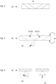
- the method includes stacking a first subset of the transparent plates 50 on a transparent base block 52 to form a first stack 50A of plates on base block 22.
- "Stacking" as used herein includes stacking plates one by one onto the base block, or stacking a pre-formed stack of plates onto the base block, or any combination of the above.
- Stacking plates to form the first stack 50A preferably includes applying an at least partially reflective coating 54 between each pair of adjacent plates 50, an in addition, in some embodiments preferably includes applying an at least partially reflective coating 54 between the first stack of plates and the base block 52.
- the at least partially reflective coating 54 applied between adjacent plates may be the same or different at least partially reflective coatings, and the at least partially reflective coating applied between the stack and the base block may be the same or different coating as compared to the coating applied between the plates of the stack.
- at least one of the at least partially reflective coatings applied between adjacent plates or between the stack of plates and the base block may be a fully reflective coating.
- Stacking plates to form the first stack 50A preferably further includes applying an adhesive coating 56 between adjacent plates in the first stack 50A and between the first stack 50A and the base block 52.
- the adhesive coating applied between adjacent plates may be the same or different than the adhesive coating applied between the stack of plates and the base block.
- the plates in the first stack 50A are preferably bonded together with a permanent adhesive, while the first stack 50A may be bonded to the base block 52 using either a temporary adhesive or a permanent adhesive depending on the desired final LOE configuration.
- the first stack 50A of plates should preferably be bonded to the base block 52 at this stage with a temporary adhesive only, while the "degenerated" LOE is preferably fabricated with the first stack 50A of plates bonded now to the base block 52 with a permanent adhesive. Therefore, at this stage, the interface between the base block 52 and the first stack 50A of plates may include the adhesive coating 56 only, as shown in Fig. 5A (e.g. as in the case of the clean corner configuration), or alternatively may include the partially reflective coating 54 as shown in Fig. 5B (e.g. as in the case of degenerated configuration).
- stacking the first subset of plates may in some cases further include the steps of: i) applying an at least partially reflective coating 54 between adjacent plates in the first stack 50A and between the first stack 50A and the base block 52; ii) bonding the plates in the first stack 50A to one another using a permanent adhesive; and iii) bonding the first stack 50A of plates to the base block 52 using a permanent adhesive.
- stacking the first subset of plates may include the steps of: i) applying an at least partially reflective coating 54 between adjacent plates in the first stack 50A; ii) bonding the plates in the first stack 50A to one another using a permanent adhesive; and iii) bonding the first stack 50A of plates to the base block 52 using a temporary adhesive.
- a temporary adhesive is used between the first stack 50A of plates and the base block 52 to facilitate temporary removal of the first stack 50A and subsequent re-bonding, as will be described below with reference to Fig. 7 .
- a sloped surface 62 (non-perpendicular to the parallel surfaces of the plates) is formed on one side of the first stack 50A of plates and the base block 52, such that the sloped surface includes at least a part of the base block.
- the sloped surface can be formed by any method known in the art, such as grinding by a grinding apparatus 63, cutting, etc.
- the angle ⁇ between the sloped surface 62 and the parallel surfaces of the plates should correspond to the desired facet angle relative to the external surfaces of the LOE.
- the first stack 50A of plates is de-bonded from the base block 52 and temporarily removed, as shown in Fig. 7 , and an at least partially reflective coating 54 is applied between the first stack 50A and the base block 52 and preferably also applied to the sloped surface part of the base block, as shown in Fig. 8 .
- the first stack 50A is subsequently re-bonded to the base block 52 using a permanent adhesive.
- the interface between the base block and the first stack 50A of plates may already include the at least partially reflective coating 54 (as shown in Fig. 5B ), thus obviating the need for removing the first stack 50A of plates at this stage to coat the base block.
- an at least partially reflective coating 54 is applied now only to the sloped surface part of the base block.
- the method further includes stacking a second subset of the plurality of plates 50 on the sloped surface 62 to form a second stack 50B of plates on the base block 52.
- the second stack 50B of plates includes an at least partially reflective coating 54 between each pair of adjacent plates.
- the interface between the base block 52 and the second stack 50B of plates also includes an at least partially reflective coating 54.
- the second stack of plates includes an adhesive coating 56 between each pair of adjacent plates and between the second stack and the base block.
- the adhesive is a permanent adhesive.
- the first stack 50A is most preferably re-bonded to the base block during, or subsequent to, the bonding of the second stack 50B to the sloped surface part of the base block 52 such that the first stack is wedged between the base block and the second stack, as shown in Fig. 9 .
- the method further includes extracting a slice 100 of the first stack 50A, the base block 52, and the second stack 50B, such that the slice 100 includes at least a part of the base block 52 interposed between plates of the first stack 50A and plates of the second stack 50B.
- the slice can be extracted using any method known in the art, such as by cutting along parallel lines (shown as dashed lines 60 in Fig. 10 ) or by grinding (e.g. by applying a grinding force to the first stack, the base block, and the second stack in directions marked by arrows 64 in Fig. 10 ).
- the width of the slice should substantially correspond to the desired distance between the parallel external surfaces 18 of the LOE.
- the cutting out or grinding out of the slice is preferably performed so that the extracted slice has two sets of internal surfaces (where adjacent plates meet) that are substantially symmetrical about an imaginary line 66 extending along a width of the slice at the mid-point of the base block element, as shown in Fig. 10 .
- the inner-most internal surfaces correspond to the coupling-in surfaces of LOE 10'.
- the extraction of slice 100 should be aided with an autocollimator and alignment device, or any known active alignment method and tools, to determine the correct angle between the cutting or grinding tool and the facets of LOE 10'.
- the method further includes lapping (e.g. using a lapping apparatus 1100 ) the external surface of slice 100 nearest to the point of intersection between the two coupling-in surfaces such that the external surface is within 0.1mm of the interface, as described above with reference to Fig. 3 ("clean corner" configuration) and Fig. 4 (overlap-type "degenerated” configuration).
- lapping e.g. using a lapping apparatus 1100
- the external surface of slice 100 nearest to the point of intersection between the two coupling-in surfaces such that the external surface is within 0.1mm of the interface, as described above with reference to Fig. 3 ("clean corner" configuration) and Fig. 4 (overlap-type "degenerated” configuration).
- the method further includes polishing slice 100 along the major external surfaces thereof, e.g. using a double side polishing 1200 apparatus, in order to achieve a sufficient degree of parallelism therebetween.
- the major external surfaces of slice 100 correspond to external surfaces 18 of LOE 10'.
- the method further includes shaping out the slice 100 so that the sides thereof correspond to the desired LOE shape.
- the slice 100 then forms a single complete symmetric LOE 10' that is similar to the known symmetric LOE 10 of Figs. 1A-1B but without a seam between combiner slices.
- slice 100 may be cut into a plurality of symmetric LOEs 10', each one of which is similar to the known symmetric LOE 10 but without a seam between combiner slices.
Landscapes
- Physics & Mathematics (AREA)
- General Physics & Mathematics (AREA)
- Optics & Photonics (AREA)
- Engineering & Computer Science (AREA)
- Microelectronics & Electronic Packaging (AREA)
- Manufacturing & Machinery (AREA)
- Optical Elements Other Than Lenses (AREA)
- Optical Couplings Of Light Guides (AREA)
- Light Guides In General And Applications Therefor (AREA)
Applications Claiming Priority (2)
| Application Number | Priority Date | Filing Date | Title |
|---|---|---|---|
| US201962792433P | 2019-01-15 | 2019-01-15 | |
| PCT/IB2020/050294 WO2020148665A1 (en) | 2019-01-15 | 2020-01-15 | Method of fabricating a symmetric light guide optical element |
Publications (4)
| Publication Number | Publication Date |
|---|---|
| EP3911983A1 EP3911983A1 (en) | 2021-11-24 |
| EP3911983A4 EP3911983A4 (en) | 2022-06-08 |
| EP3911983C0 EP3911983C0 (en) | 2024-02-14 |
| EP3911983B1 true EP3911983B1 (en) | 2024-02-14 |
Family
ID=71614310
Family Applications (1)
| Application Number | Title | Priority Date | Filing Date |
|---|---|---|---|
| EP20741433.5A Active EP3911983B1 (en) | 2019-01-15 | 2020-01-15 | Method of fabricating a symmetric light guide optical element |
Country Status (9)
| Country | Link |
|---|---|
| US (1) | US11598958B2 (https=) |
| EP (1) | EP3911983B1 (https=) |
| JP (1) | JP7489115B2 (https=) |
| KR (1) | KR102816729B1 (https=) |
| CN (1) | CN113260889B (https=) |
| IL (1) | IL284306B2 (https=) |
| MY (1) | MY206231A (https=) |
| TW (1) | TWI820285B (https=) |
| WO (1) | WO2020148665A1 (https=) |
Families Citing this family (11)
| Publication number | Priority date | Publication date | Assignee | Title |
|---|---|---|---|---|
| IL237337B (en) | 2015-02-19 | 2020-03-31 | Amitai Yaakov | A compact head-up display system with a uniform image |
| IL309806B2 (en) | 2018-09-09 | 2025-11-01 | Lumus Ltd | Optical systems including light-guide optical elements with two-dimensional expansion |
| CN112969955B (zh) | 2018-11-08 | 2023-05-26 | 鲁姆斯有限公司 | 具有二向色分束器颜色组合器的光学装置和系统 |
| TWM642752U (zh) | 2018-11-08 | 2023-06-21 | 以色列商魯姆斯有限公司 | 用於將圖像顯示到觀察者的眼睛中的顯示器 |
| WO2020174433A1 (en) | 2019-02-28 | 2020-09-03 | Lumus Ltd. | Compact collimated image projector |
| WO2020183229A1 (en) | 2019-03-12 | 2020-09-17 | Lumus Ltd. | Image projector |
| KR102622406B1 (ko) | 2019-11-25 | 2024-01-05 | 루머스 리미티드 | 도파관의 표면을 폴리싱하는 방법 |
| IL270991B (en) | 2019-11-27 | 2020-07-30 | Lumus Ltd | A light guide with an optical element to perform polarization mixing |
| KR102939032B1 (ko) | 2019-12-05 | 2026-03-16 | 루머스 리미티드 | 상보 코팅된 부분적 반사체를 채용하는 도광 광학 소자, 및 광산란을 감소시킨 도광 광학 소자 |
| DE212021000276U1 (de) | 2020-05-12 | 2022-11-03 | Lumus Ltd. | Drehbarer Lichtleiter |
| IL309212B2 (en) * | 2021-06-07 | 2024-06-01 | Lumus Ltd | Fabrication methods of optical aperture multipliers with rectangular waveguides |
Family Cites Families (103)
| Publication number | Priority date | Publication date | Assignee | Title |
|---|---|---|---|---|
| US4017158A (en) | 1975-03-17 | 1977-04-12 | E. I. Du Pont De Nemours And Company | Spatial frequency carrier and process of preparing same |
| US5005320A (en) | 1990-03-30 | 1991-04-09 | E. I. Du Pont De Nemours And Company | Method and apparatus for tapering an end of an elongated object |
| US5136426A (en) | 1991-02-27 | 1992-08-04 | Advanced Laser Projection, Inc. | Light projection apparatus |
| US5515184A (en) | 1991-11-12 | 1996-05-07 | The University Of Alabama In Huntsville | Waveguide hologram illuminators |
| US5882773A (en) | 1993-10-13 | 1999-03-16 | The Regents Of The University Of California | Optical coatings of variable refractive index and high laser-resistance from physical-vapor-deposited perfluorinated amorphous polymer |
| US5784656A (en) | 1994-12-05 | 1998-07-21 | Nikon Corporation | Camera with light dividing devices |
| US5818618A (en) | 1996-03-22 | 1998-10-06 | Motorola, Inc. | High-speed serial simplex broadcast data distribution using optics |
| US6404550B1 (en) | 1996-07-25 | 2002-06-11 | Seiko Epson Corporation | Optical element suitable for projection display apparatus |
| US6542307B2 (en) | 2000-10-20 | 2003-04-01 | Three-Five Systems, Inc. | Compact near-eye illumination system |
| US20020093701A1 (en) | 2000-12-29 | 2002-07-18 | Xiaoxiao Zhang | Holographic multifocal lens |
| US6604839B2 (en) | 2001-06-15 | 2003-08-12 | Lumileds Lighting, U.S., Llc | Multi-chip LED color mixing by diffraction |
| JP4751534B2 (ja) | 2001-07-24 | 2011-08-17 | 大日本印刷株式会社 | 光学系及びそれを用いた装置 |
| WO2003027569A1 (en) | 2001-09-26 | 2003-04-03 | Koninklijke Philips Electronics N.V. | Waveguide, edge-lit illumination arrangement and display comprising such |
| US7221512B2 (en) | 2002-01-24 | 2007-05-22 | Nanoventions, Inc. | Light control material for displaying color information, and images |
| IL148804A (en) | 2002-03-21 | 2007-02-11 | Yaacov Amitai | Optical device |
| AU2003279909A1 (en) | 2002-07-01 | 2004-01-19 | Toray Plastics (America), Inc. | Patterned deposition of refractive layers for high security holograms |
| US6805490B2 (en) | 2002-09-30 | 2004-10-19 | Nokia Corporation | Method and system for beam expansion in a display device |
| CN100416340C (zh) | 2003-04-25 | 2008-09-03 | 微型光学公司 | 双目镜观察系统 |
| US7245408B1 (en) | 2003-10-10 | 2007-07-17 | Zebra Imaging, Inc. | Systems and methods for producing wide field-of-view holographic displays |
| US7418170B2 (en) | 2004-03-29 | 2008-08-26 | Sony Corporation | Optical device and virtual image display device |
| IL162573A (en) * | 2004-06-17 | 2013-05-30 | Lumus Ltd | Optical component in a large key conductive substrate |
| US20060126181A1 (en) | 2004-12-13 | 2006-06-15 | Nokia Corporation | Method and system for beam expansion in a display device |
| US7206107B2 (en) | 2004-12-13 | 2007-04-17 | Nokia Corporation | Method and system for beam expansion in a display device |
| US7162136B1 (en) | 2004-12-22 | 2007-01-09 | West Virginia University | Non-circular, mechanically variable optical attenuator |
| JP4810949B2 (ja) | 2005-09-29 | 2011-11-09 | ソニー株式会社 | 光学装置及び画像表示装置 |
| WO2008081070A1 (en) | 2006-12-28 | 2008-07-10 | Nokia Corporation | Device for expanding an exit pupil in two dimensions |
| US20080309998A1 (en) | 2007-06-13 | 2008-12-18 | Sharp Kabushiki Kaisha | Hologram element deflecting optical beam, hologram element fabricating apparatus, hologram element fabricating method, deflection optical unit, and information recording apparatus and information reconstructing apparatus using deflection optical unit |
| US7589901B2 (en) | 2007-07-10 | 2009-09-15 | Microvision, Inc. | Substrate-guided relays for use with scanned beam light sources |
| CN101359100B (zh) | 2007-08-03 | 2012-03-28 | 鸿富锦精密工业(深圳)有限公司 | 偏振光转换器及具有该偏振光转换器的投影系统 |
| WO2009109965A2 (en) * | 2008-03-04 | 2009-09-11 | Elbit Systems Electro Optics Elop Ltd. | Head up display utilizing an lcd and a diffuser |
| US8369019B2 (en) | 2008-04-14 | 2013-02-05 | Bae Systems Plc | Waveguides |
| TW200947002A (en) | 2008-05-14 | 2009-11-16 | Ind Tech Res Inst | Gratings at optical fiber side and coupling apparatus using the same |
| JP4706737B2 (ja) | 2008-08-18 | 2011-06-22 | ソニー株式会社 | 画像表示装置 |
| JP5344550B2 (ja) | 2008-08-26 | 2013-11-20 | キヤノン株式会社 | 画像投射装置及び画像表示システム |
| US8233204B1 (en) | 2009-09-30 | 2012-07-31 | Rockwell Collins, Inc. | Optical displays |
| US9075184B2 (en) | 2012-04-17 | 2015-07-07 | Milan Momcilo Popovich | Compact edge illuminated diffractive display |
| FR2957683B1 (fr) | 2010-03-17 | 2012-03-23 | Delphi Tech Inc | Combineur diffractif pour afficheur tete haute couleur |
| EP2625845B1 (en) | 2010-10-04 | 2021-03-03 | Gerard Dirk Smits | System and method for 3-d projection and enhancements for interactivity |
| WO2012088610A1 (en) | 2010-12-29 | 2012-07-05 | Socpra Sciences Et Génie S.E.C. | Low loss directional coupling between highly dissimilar optical waveguides for high refractive index integrated photonic circuits |
| US8189263B1 (en) | 2011-04-01 | 2012-05-29 | Google Inc. | Image waveguide with mirror arrays |
| US20150077312A1 (en) | 2011-05-13 | 2015-03-19 | Google Inc. | Near-to-eye display having adaptive optics |
| GB201114149D0 (en) | 2011-08-17 | 2011-10-05 | Bae Systems Plc | Projection display |
| US8903207B1 (en) | 2011-09-30 | 2014-12-02 | Rockwell Collins, Inc. | System for and method of extending vertical field of view in head up display utilizing a waveguide combiner |
| US9207461B2 (en) | 2011-11-18 | 2015-12-08 | Ciena Corporation | Fiber optical package interconnect |
| CN102402005B (zh) | 2011-12-06 | 2015-11-25 | 北京理工大学 | 自由曲面双焦面单目立体头盔显示器装置 |
| US8665178B1 (en) | 2012-03-01 | 2014-03-04 | Google, Inc. | Partially-reflective waveguide stack and heads-up display using same |
| US9274338B2 (en) | 2012-03-21 | 2016-03-01 | Microsoft Technology Licensing, Llc | Increasing field of view of reflective waveguide |
| EP2842003B1 (en) | 2012-04-25 | 2019-02-27 | Rockwell Collins, Inc. | Holographic wide angle display |
| US9456744B2 (en) | 2012-05-11 | 2016-10-04 | Digilens, Inc. | Apparatus for eye tracking |
| AU2013274359B2 (en) | 2012-06-11 | 2017-05-25 | Magic Leap, Inc. | Multiple depth plane three-dimensional display using a wave guide reflector array projector |
| US9019615B2 (en) | 2012-06-12 | 2015-04-28 | Microsoft Technology Licensing, Llc | Wide field-of-view virtual image projector |
| US9581762B2 (en) | 2012-09-16 | 2017-02-28 | Shalom Wertsberger | Pixel structure using a tapered core waveguide, image sensors and camera using same |
| US9151881B2 (en) | 2012-11-12 | 2015-10-06 | Kla-Tencor Corporation | Phase grating for mask inspection system |
| US9933684B2 (en) | 2012-11-16 | 2018-04-03 | Rockwell Collins, Inc. | Transparent waveguide display providing upper and lower fields of view having a specific light output aperture configuration |
| JP2014109717A (ja) * | 2012-12-03 | 2014-06-12 | Samsung R&D Institute Japan Co Ltd | 導光ユニットおよび映像表示装置 |
| EP2929378A1 (en) | 2012-12-10 | 2015-10-14 | BAE Systems PLC | Display comprising an optical waveguide and switchable diffraction gratings and method of producing the same |
| WO2015001839A1 (ja) | 2013-07-04 | 2015-01-08 | ソニー株式会社 | 表示装置 |
| WO2015006784A2 (en) | 2013-07-12 | 2015-01-15 | Magic Leap, Inc. | Planar waveguide apparatus with diffraction element(s) and system employing same |
| US9349165B2 (en) | 2013-10-23 | 2016-05-24 | Adobe Systems Incorporated | Automatically suggesting regions for blur kernel estimation |
| KR102651578B1 (ko) | 2013-11-27 | 2024-03-25 | 매직 립, 인코포레이티드 | 가상 및 증강 현실 시스템들 및 방법들 |
| JP6255981B2 (ja) | 2013-12-24 | 2018-01-10 | セイコーエプソン株式会社 | 導光装置、虚像表示装置及び導光装置の製造方法 |
| US9651784B2 (en) | 2014-01-21 | 2017-05-16 | Osterhout Group, Inc. | See-through computer display systems |
| JP6362364B2 (ja) | 2014-03-10 | 2018-07-25 | キヤノン株式会社 | 回折格子、および回折格子の製造方法 |
| JP6413366B2 (ja) * | 2014-06-09 | 2018-10-31 | セイコーエプソン株式会社 | 偏光変換素子、及びプロジェクター |
| EP2995552B1 (en) | 2014-09-09 | 2018-05-02 | Airbus Defence and Space GmbH | Chamber in an airfoil |
| WO2016042283A1 (en) | 2014-09-19 | 2016-03-24 | Milan Momcilo Popovich | Method and apparatus for generating input images for holographic waveguide displays |
| WO2016051439A1 (ja) | 2014-10-03 | 2016-04-07 | オリンパス株式会社 | 表示装置 |
| US10008822B2 (en) | 2014-10-10 | 2018-06-26 | The Boeing Company | Laser system and method for controlling the wave front of a laser beam |
| IL236491B (en) * | 2014-12-25 | 2020-11-30 | Lumus Ltd | A method for manufacturing an optical component in a conductive substrate |
| US10180520B2 (en) | 2015-08-24 | 2019-01-15 | Akonia Holographics, Llc | Skew mirrors, methods of use, and methods of manufacture |
| TWI574046B (zh) | 2015-09-30 | 2017-03-11 | 中強光電股份有限公司 | 光學模組以及頭戴式顯示裝置 |
| WO2017062483A1 (en) | 2015-10-05 | 2017-04-13 | Magic Leap, Inc. | Microlens collimator for scanning optical fiber in virtual/augmented reality system |
| US9791696B2 (en) | 2015-11-10 | 2017-10-17 | Microsoft Technology Licensing, Llc | Waveguide gratings to improve intensity distributions |
| CN107290816B (zh) | 2016-03-30 | 2020-04-24 | 中强光电股份有限公司 | 光波导元件以及具有此光波导元件的头戴式显示装置 |
| CN107783293A (zh) | 2016-08-31 | 2018-03-09 | 中强光电股份有限公司 | 穿戴式装置及导光元件 |
| US10317679B2 (en) | 2016-04-04 | 2019-06-11 | Akonia Holographics, Llc | Light homogenization |
| CN107329256B (zh) | 2016-04-28 | 2022-04-05 | 江苏慧光电子科技有限公司 | 显示装置及其控制方法 |
| CN106226902A (zh) * | 2016-07-18 | 2016-12-14 | 深圳珑璟光电技术有限公司 | 用于增强现实显示的交互头戴显示设备 |
| TWI669530B (zh) * | 2016-08-18 | 2019-08-21 | 以色列商盧姆斯有限公司 | 具有一致影像之小型頭戴式顯示系統 |
| WO2018039273A1 (en) | 2016-08-22 | 2018-03-01 | Magic Leap, Inc. | Dithering methods and apparatus for wearable display device |
| US10466479B2 (en) | 2016-10-07 | 2019-11-05 | Coretronic Corporation | Head-mounted display apparatus and optical system |
| JP7187022B2 (ja) | 2016-10-09 | 2022-12-12 | ルムス エルティーディー. | 長方形導波路を使用する開口乗算器 |
| US10444510B1 (en) | 2016-10-11 | 2019-10-15 | Facebook Technologies, Llc | Opposed gratings in a waveguide display |
| JP6980209B2 (ja) | 2017-02-22 | 2021-12-15 | ルムス エルティーディー. | 光ガイド光学アセンブリ |
| CN117572644A (zh) * | 2017-03-22 | 2024-02-20 | 鲁姆斯有限公司 | 用于生产光导光学元件的方法和光学系统 |
| IL251645B (en) * | 2017-04-06 | 2018-08-30 | Lumus Ltd | Waveguide and method of production |
| TW201843008A (zh) | 2017-04-27 | 2018-12-16 | 美商康寧公司 | 用於光耦合之玻璃邊緣處理 |
| US10338400B2 (en) | 2017-07-03 | 2019-07-02 | Holovisions LLC | Augmented reality eyewear with VAPE or wear technology |
| JP7174929B2 (ja) | 2017-07-19 | 2022-11-18 | ルムス エルティーディー. | Loeを介するlcos照明 |
| US10422995B2 (en) | 2017-07-24 | 2019-09-24 | Mentor Acquisition One, Llc | See-through computer display systems with stray light management |
| CN107329273B (zh) | 2017-08-29 | 2020-07-07 | 京东方科技集团股份有限公司 | 一种近眼显示装置 |
| CN107728253B (zh) | 2017-11-02 | 2021-03-12 | 北京亮亮视野科技有限公司 | 宽带宽、高均匀性的级联分光膜阵列波导及其应用 |
| CN107643559A (zh) | 2017-11-13 | 2018-01-30 | 北京理工大学 | 基于反射式波导耦合器的光线传导和分离方法及装置 |
| CN207424391U (zh) | 2017-11-22 | 2018-05-29 | 深圳创维新世界科技有限公司 | 近眼显示装置 |
| CN107966820B (zh) | 2017-12-27 | 2021-03-02 | 北京灵犀微光科技有限公司 | 波导显示装置 |
| JPWO2019150461A1 (ja) | 2018-01-31 | 2021-01-07 | 株式会社島津製作所 | 画像表示装置 |
| US10488666B2 (en) * | 2018-02-10 | 2019-11-26 | Daqri, Llc | Optical waveguide devices, methods and systems incorporating same |
| US10345519B1 (en) | 2018-04-11 | 2019-07-09 | Microsoft Technology Licensing, Llc | Integrated optical beam steering system |
| NL2024203B1 (en) | 2019-11-08 | 2021-07-20 | Gustomsc B V | Extendable lattice type crane boom, and method for operating a crane including an extendable boom. |
| KR102622406B1 (ko) | 2019-11-25 | 2024-01-05 | 루머스 리미티드 | 도파관의 표면을 폴리싱하는 방법 |
| CN114846400A (zh) | 2019-12-19 | 2022-08-02 | 鲁姆斯有限公司 | 使用相位图像生成器的图像投影仪 |
| IL294794B1 (en) | 2020-02-02 | 2026-04-01 | Lumus Ltd | Method for manufacturing light-guiding optical elements |
| JP7514562B2 (ja) | 2020-03-23 | 2024-07-11 | ルムス エルティーディー. | ゴースト画像を軽減するための光学デバイス |
-
2020
- 2020-01-15 JP JP2021531652A patent/JP7489115B2/ja active Active
- 2020-01-15 US US17/416,492 patent/US11598958B2/en active Active
- 2020-01-15 WO PCT/IB2020/050294 patent/WO2020148665A1/en not_active Ceased
- 2020-01-15 TW TW109101430A patent/TWI820285B/zh active
- 2020-01-15 MY MYPI2021003463A patent/MY206231A/en unknown
- 2020-01-15 IL IL284306A patent/IL284306B2/en unknown
- 2020-01-15 EP EP20741433.5A patent/EP3911983B1/en active Active
- 2020-01-15 CN CN202080007825.XA patent/CN113260889B/zh active Active
- 2020-01-15 KR KR1020217017497A patent/KR102816729B1/ko active Active
Also Published As
| Publication number | Publication date |
|---|---|
| KR20210113594A (ko) | 2021-09-16 |
| EP3911983A1 (en) | 2021-11-24 |
| KR102816729B1 (ko) | 2025-06-04 |
| WO2020148665A1 (en) | 2020-07-23 |
| TW202033994A (zh) | 2020-09-16 |
| JP2022516226A (ja) | 2022-02-25 |
| EP3911983C0 (en) | 2024-02-14 |
| US20220043269A1 (en) | 2022-02-10 |
| IL284306A (en) | 2021-08-31 |
| IL284306B (en) | 2022-12-01 |
| TWI820285B (zh) | 2023-11-01 |
| CN113260889B (zh) | 2023-04-18 |
| CN113260889A (zh) | 2021-08-13 |
| IL284306B2 (en) | 2023-04-01 |
| JP7489115B2 (ja) | 2024-05-23 |
| US11598958B2 (en) | 2023-03-07 |
| MY206231A (en) | 2024-12-05 |
| EP3911983A4 (en) | 2022-06-08 |
Similar Documents
| Publication | Publication Date | Title |
|---|---|---|
| EP3911983B1 (en) | Method of fabricating a symmetric light guide optical element | |
| JP7770689B2 (ja) | 導光光学素子を生産するための方法 | |
| JP7407458B2 (ja) | 二次元の拡張を有する導光光学素子を含む光学システム | |
| US20220308352A1 (en) | Systems for and methods of using fold gratings for dual axis expansion | |
| US20180292599A1 (en) | Light-guide optical element and method of its manufacture | |
| TWI871513B (zh) | 具有矩形波導的光學孔徑倍增器的製造方法及光學結構 | |
| WO2013179405A1 (ja) | 反射型面対称結像素子の製造方法、反射型面対称結像素子、前記反射型面対称結像素子を備えた空間映像表示装置 | |
| JP2023528564A (ja) | 複合導光光学素子 | |
| WO2016132984A1 (ja) | 光学素子、それを用いた反射型空中結像素子及びこれらの製造方法 | |
| KR102413405B1 (ko) | 출사동 확장이 가능한 반사형 도파관 디스플레이의 제조 방법 | |
| EP4176302B1 (en) | Full-color waveguide combiner with embedded metagrating | |
| WO2006064500A2 (en) | Device and method for optical resizing | |
| WO2025120638A1 (en) | Methods for fabricating light-guide optical elements | |
| WO2025128849A1 (en) | Hybrid waveguide for low image leakage, low cosmetic defects and high efficiency ar displays |
Legal Events
| Date | Code | Title | Description |
|---|---|---|---|
| STAA | Information on the status of an ep patent application or granted ep patent |
Free format text: STATUS: THE INTERNATIONAL PUBLICATION HAS BEEN MADE |
|
| PUAI | Public reference made under article 153(3) epc to a published international application that has entered the european phase |
Free format text: ORIGINAL CODE: 0009012 |
|
| STAA | Information on the status of an ep patent application or granted ep patent |
Free format text: STATUS: REQUEST FOR EXAMINATION WAS MADE |
|
| 17P | Request for examination filed |
Effective date: 20210727 |
|
| AK | Designated contracting states |
Kind code of ref document: A1 Designated state(s): AL AT BE BG CH CY CZ DE DK EE ES FI FR GB GR HR HU IE IS IT LI LT LU LV MC MK MT NL NO PL PT RO RS SE SI SK SM TR |
|
| DAV | Request for validation of the european patent (deleted) | ||
| DAX | Request for extension of the european patent (deleted) | ||
| A4 | Supplementary search report drawn up and despatched |
Effective date: 20220506 |
|
| RIC1 | Information provided on ipc code assigned before grant |
Ipc: G02B 27/28 20060101ALI20220429BHEP Ipc: G02B 27/00 20060101ALI20220429BHEP Ipc: G02B 27/14 20060101ALI20220429BHEP Ipc: G02B 27/10 20060101ALI20220429BHEP Ipc: G02B 6/36 20060101ALI20220429BHEP Ipc: G02B 6/12 20060101ALI20220429BHEP Ipc: F21V 8/00 20060101ALI20220429BHEP Ipc: G02B 27/01 20060101ALI20220429BHEP Ipc: G02B 6/13 20060101AFI20220429BHEP |
|
| STAA | Information on the status of an ep patent application or granted ep patent |
Free format text: STATUS: EXAMINATION IS IN PROGRESS |
|
| 17Q | First examination report despatched |
Effective date: 20230403 |
|
| GRAP | Despatch of communication of intention to grant a patent |
Free format text: ORIGINAL CODE: EPIDOSNIGR1 |
|
| STAA | Information on the status of an ep patent application or granted ep patent |
Free format text: STATUS: GRANT OF PATENT IS INTENDED |
|
| INTG | Intention to grant announced |
Effective date: 20230919 |
|
| GRAS | Grant fee paid |
Free format text: ORIGINAL CODE: EPIDOSNIGR3 |
|
| GRAA | (expected) grant |
Free format text: ORIGINAL CODE: 0009210 |
|
| STAA | Information on the status of an ep patent application or granted ep patent |
Free format text: STATUS: THE PATENT HAS BEEN GRANTED |
|
| AK | Designated contracting states |
Kind code of ref document: B1 Designated state(s): AL AT BE BG CH CY CZ DE DK EE ES FI FR GB GR HR HU IE IS IT LI LT LU LV MC MK MT NL NO PL PT RO RS SE SI SK SM TR |
|
| REG | Reference to a national code |
Ref country code: GB Ref legal event code: FG4D |
|
| REG | Reference to a national code |
Ref country code: CH Ref legal event code: EP |
|
| REG | Reference to a national code |
Ref country code: DE Ref legal event code: R096 Ref document number: 602020025694 Country of ref document: DE |
|
| REG | Reference to a national code |
Ref country code: IE Ref legal event code: FG4D |
|
| U01 | Request for unitary effect filed |
Effective date: 20240301 |
|
| U07 | Unitary effect registered |
Designated state(s): AT BE BG DE DK EE FI FR IT LT LU LV MT NL PT SE SI Effective date: 20240307 |
|
| PG25 | Lapsed in a contracting state [announced via postgrant information from national office to epo] |
Ref country code: IS Free format text: LAPSE BECAUSE OF FAILURE TO SUBMIT A TRANSLATION OF THE DESCRIPTION OR TO PAY THE FEE WITHIN THE PRESCRIBED TIME-LIMIT Effective date: 20240614 |
|
| PG25 | Lapsed in a contracting state [announced via postgrant information from national office to epo] |
Ref country code: GR Free format text: LAPSE BECAUSE OF FAILURE TO SUBMIT A TRANSLATION OF THE DESCRIPTION OR TO PAY THE FEE WITHIN THE PRESCRIBED TIME-LIMIT Effective date: 20240515 |
|
| PG25 | Lapsed in a contracting state [announced via postgrant information from national office to epo] |
Ref country code: RS Free format text: LAPSE BECAUSE OF FAILURE TO SUBMIT A TRANSLATION OF THE DESCRIPTION OR TO PAY THE FEE WITHIN THE PRESCRIBED TIME-LIMIT Effective date: 20240514 Ref country code: HR Free format text: LAPSE BECAUSE OF FAILURE TO SUBMIT A TRANSLATION OF THE DESCRIPTION OR TO PAY THE FEE WITHIN THE PRESCRIBED TIME-LIMIT Effective date: 20240214 |
|
| PG25 | Lapsed in a contracting state [announced via postgrant information from national office to epo] |
Ref country code: ES Free format text: LAPSE BECAUSE OF FAILURE TO SUBMIT A TRANSLATION OF THE DESCRIPTION OR TO PAY THE FEE WITHIN THE PRESCRIBED TIME-LIMIT Effective date: 20240214 |
|
| PG25 | Lapsed in a contracting state [announced via postgrant information from national office to epo] |
Ref country code: RS Free format text: LAPSE BECAUSE OF FAILURE TO SUBMIT A TRANSLATION OF THE DESCRIPTION OR TO PAY THE FEE WITHIN THE PRESCRIBED TIME-LIMIT Effective date: 20240514 Ref country code: NO Free format text: LAPSE BECAUSE OF FAILURE TO SUBMIT A TRANSLATION OF THE DESCRIPTION OR TO PAY THE FEE WITHIN THE PRESCRIBED TIME-LIMIT Effective date: 20240514 Ref country code: IS Free format text: LAPSE BECAUSE OF FAILURE TO SUBMIT A TRANSLATION OF THE DESCRIPTION OR TO PAY THE FEE WITHIN THE PRESCRIBED TIME-LIMIT Effective date: 20240614 Ref country code: HR Free format text: LAPSE BECAUSE OF FAILURE TO SUBMIT A TRANSLATION OF THE DESCRIPTION OR TO PAY THE FEE WITHIN THE PRESCRIBED TIME-LIMIT Effective date: 20240214 Ref country code: GR Free format text: LAPSE BECAUSE OF FAILURE TO SUBMIT A TRANSLATION OF THE DESCRIPTION OR TO PAY THE FEE WITHIN THE PRESCRIBED TIME-LIMIT Effective date: 20240515 Ref country code: ES Free format text: LAPSE BECAUSE OF FAILURE TO SUBMIT A TRANSLATION OF THE DESCRIPTION OR TO PAY THE FEE WITHIN THE PRESCRIBED TIME-LIMIT Effective date: 20240214 |
|
| PG25 | Lapsed in a contracting state [announced via postgrant information from national office to epo] |
Ref country code: PL Free format text: LAPSE BECAUSE OF FAILURE TO SUBMIT A TRANSLATION OF THE DESCRIPTION OR TO PAY THE FEE WITHIN THE PRESCRIBED TIME-LIMIT Effective date: 20240214 |
|
| PG25 | Lapsed in a contracting state [announced via postgrant information from national office to epo] |
Ref country code: PL Free format text: LAPSE BECAUSE OF FAILURE TO SUBMIT A TRANSLATION OF THE DESCRIPTION OR TO PAY THE FEE WITHIN THE PRESCRIBED TIME-LIMIT Effective date: 20240214 |
|
| PG25 | Lapsed in a contracting state [announced via postgrant information from national office to epo] |
Ref country code: SM Free format text: LAPSE BECAUSE OF FAILURE TO SUBMIT A TRANSLATION OF THE DESCRIPTION OR TO PAY THE FEE WITHIN THE PRESCRIBED TIME-LIMIT Effective date: 20240214 |
|
| PG25 | Lapsed in a contracting state [announced via postgrant information from national office to epo] |
Ref country code: CZ Free format text: LAPSE BECAUSE OF FAILURE TO SUBMIT A TRANSLATION OF THE DESCRIPTION OR TO PAY THE FEE WITHIN THE PRESCRIBED TIME-LIMIT Effective date: 20240214 |
|
| PG25 | Lapsed in a contracting state [announced via postgrant information from national office to epo] |
Ref country code: SK Free format text: LAPSE BECAUSE OF FAILURE TO SUBMIT A TRANSLATION OF THE DESCRIPTION OR TO PAY THE FEE WITHIN THE PRESCRIBED TIME-LIMIT Effective date: 20240214 |
|
| PG25 | Lapsed in a contracting state [announced via postgrant information from national office to epo] |
Ref country code: SM Free format text: LAPSE BECAUSE OF FAILURE TO SUBMIT A TRANSLATION OF THE DESCRIPTION OR TO PAY THE FEE WITHIN THE PRESCRIBED TIME-LIMIT Effective date: 20240214 Ref country code: SK Free format text: LAPSE BECAUSE OF FAILURE TO SUBMIT A TRANSLATION OF THE DESCRIPTION OR TO PAY THE FEE WITHIN THE PRESCRIBED TIME-LIMIT Effective date: 20240214 Ref country code: RO Free format text: LAPSE BECAUSE OF FAILURE TO SUBMIT A TRANSLATION OF THE DESCRIPTION OR TO PAY THE FEE WITHIN THE PRESCRIBED TIME-LIMIT Effective date: 20240214 Ref country code: CZ Free format text: LAPSE BECAUSE OF FAILURE TO SUBMIT A TRANSLATION OF THE DESCRIPTION OR TO PAY THE FEE WITHIN THE PRESCRIBED TIME-LIMIT Effective date: 20240214 |
|
| REG | Reference to a national code |
Ref country code: DE Ref legal event code: R097 Ref document number: 602020025694 Country of ref document: DE |
|
| PLBE | No opposition filed within time limit |
Free format text: ORIGINAL CODE: 0009261 |
|
| STAA | Information on the status of an ep patent application or granted ep patent |
Free format text: STATUS: NO OPPOSITION FILED WITHIN TIME LIMIT |
|
| 26N | No opposition filed |
Effective date: 20241115 |
|
| U20 | Renewal fee for the european patent with unitary effect paid |
Year of fee payment: 6 Effective date: 20250130 |
|
| REG | Reference to a national code |
Ref country code: CH Ref legal event code: PL |
|
| PG25 | Lapsed in a contracting state [announced via postgrant information from national office to epo] |
Ref country code: MC Free format text: LAPSE BECAUSE OF FAILURE TO SUBMIT A TRANSLATION OF THE DESCRIPTION OR TO PAY THE FEE WITHIN THE PRESCRIBED TIME-LIMIT Effective date: 20240214 |
|
| PG25 | Lapsed in a contracting state [announced via postgrant information from national office to epo] |
Ref country code: CH Free format text: LAPSE BECAUSE OF NON-PAYMENT OF DUE FEES Effective date: 20250131 |
|
| PG25 | Lapsed in a contracting state [announced via postgrant information from national office to epo] |
Ref country code: IE Free format text: LAPSE BECAUSE OF NON-PAYMENT OF DUE FEES Effective date: 20250115 |
|
| U20 | Renewal fee for the european patent with unitary effect paid |
Year of fee payment: 7 Effective date: 20260126 |
|
| PGFP | Annual fee paid to national office [announced via postgrant information from national office to epo] |
Ref country code: GB Payment date: 20260126 Year of fee payment: 7 |