EP3909808A1 - Vehicle loading system for a vehicle cabin - Google Patents
Vehicle loading system for a vehicle cabin Download PDFInfo
- Publication number
- EP3909808A1 EP3909808A1 EP21020150.5A EP21020150A EP3909808A1 EP 3909808 A1 EP3909808 A1 EP 3909808A1 EP 21020150 A EP21020150 A EP 21020150A EP 3909808 A1 EP3909808 A1 EP 3909808A1
- Authority
- EP
- European Patent Office
- Prior art keywords
- vehicle
- vehicle cabin
- cabin
- movement device
- movement
- Prior art date
- Legal status (The legal status is an assumption and is not a legal conclusion. Google has not performed a legal analysis and makes no representation as to the accuracy of the status listed.)
- Granted
Links
- 238000011068 loading method Methods 0.000 title claims abstract description 41
- 238000000034 method Methods 0.000 claims abstract description 19
- 235000004443 Ricinus communis Nutrition 0.000 description 2
- 240000000528 Ricinus communis Species 0.000 description 2
- 238000005096 rolling process Methods 0.000 description 2
- 239000004576 sand Substances 0.000 description 2
- 239000011324 bead Substances 0.000 description 1
- 238000006073 displacement reaction Methods 0.000 description 1
Images


Classifications
-
- B—PERFORMING OPERATIONS; TRANSPORTING
- B60—VEHICLES IN GENERAL
- B60P—VEHICLES ADAPTED FOR LOAD TRANSPORTATION OR TO TRANSPORT, TO CARRY, OR TO COMPRISE SPECIAL LOADS OR OBJECTS
- B60P1/00—Vehicles predominantly for transporting loads and modified to facilitate loading, consolidating the load, or unloading
- B60P1/64—Vehicles predominantly for transporting loads and modified to facilitate loading, consolidating the load, or unloading the load supporting or containing element being readily removable
- B60P1/6418—Vehicles predominantly for transporting loads and modified to facilitate loading, consolidating the load, or unloading the load supporting or containing element being readily removable the load-transporting element being a container or similar
- B60P1/6427—Vehicles predominantly for transporting loads and modified to facilitate loading, consolidating the load, or unloading the load supporting or containing element being readily removable the load-transporting element being a container or similar the load-transporting element being shifted horizontally in a fore and aft direction, combined or not with a vertical displacement
-
- B—PERFORMING OPERATIONS; TRANSPORTING
- B60—VEHICLES IN GENERAL
- B60P—VEHICLES ADAPTED FOR LOAD TRANSPORTATION OR TO TRANSPORT, TO CARRY, OR TO COMPRISE SPECIAL LOADS OR OBJECTS
- B60P3/00—Vehicles adapted to transport, to carry or to comprise special loads or objects
- B60P3/32—Vehicles adapted to transport, to carry or to comprise special loads or objects comprising living accommodation for people, e.g. caravans, camping, or like vehicles
- B60P3/34—Vehicles adapted to transport, to carry or to comprise special loads or objects comprising living accommodation for people, e.g. caravans, camping, or like vehicles the living accommodation being expansible, collapsible or capable of rearrangement
-
- B—PERFORMING OPERATIONS; TRANSPORTING
- B60—VEHICLES IN GENERAL
- B60J—WINDOWS, WINDSCREENS, NON-FIXED ROOFS, DOORS, OR SIMILAR DEVICES FOR VEHICLES; REMOVABLE EXTERNAL PROTECTIVE COVERINGS SPECIALLY ADAPTED FOR VEHICLES
- B60J7/00—Non-fixed roofs; Roofs with movable panels, e.g. rotary sunroofs
- B60J7/02—Non-fixed roofs; Roofs with movable panels, e.g. rotary sunroofs of sliding type, e.g. comprising guide shoes
- B60J7/04—Non-fixed roofs; Roofs with movable panels, e.g. rotary sunroofs of sliding type, e.g. comprising guide shoes with rigid plate-like element or elements, e.g. open roofs with harmonica-type folding rigid panels
- B60J7/041—Non-fixed roofs; Roofs with movable panels, e.g. rotary sunroofs of sliding type, e.g. comprising guide shoes with rigid plate-like element or elements, e.g. open roofs with harmonica-type folding rigid panels for utility vehicles, e.g. with slidable and foldable rigid panels
- B60J7/042—Non-fixed roofs; Roofs with movable panels, e.g. rotary sunroofs of sliding type, e.g. comprising guide shoes with rigid plate-like element or elements, e.g. open roofs with harmonica-type folding rigid panels for utility vehicles, e.g. with slidable and foldable rigid panels with a vertical lifting or folding movement
-
- B—PERFORMING OPERATIONS; TRANSPORTING
- B60—VEHICLES IN GENERAL
- B60J—WINDOWS, WINDSCREENS, NON-FIXED ROOFS, DOORS, OR SIMILAR DEVICES FOR VEHICLES; REMOVABLE EXTERNAL PROTECTIVE COVERINGS SPECIALLY ADAPTED FOR VEHICLES
- B60J7/00—Non-fixed roofs; Roofs with movable panels, e.g. rotary sunroofs
- B60J7/08—Non-fixed roofs; Roofs with movable panels, e.g. rotary sunroofs of non-sliding type, i.e. movable or removable roofs or panels, e.g. let-down tops or roofs capable of being easily detached or of assuming a collapsed or inoperative position
- B60J7/16—Non-fixed roofs; Roofs with movable panels, e.g. rotary sunroofs of non-sliding type, i.e. movable or removable roofs or panels, e.g. let-down tops or roofs capable of being easily detached or of assuming a collapsed or inoperative position non-foldable and rigid, e.g. a one-piece hard-top or a single rigid roof panel
- B60J7/1607—Non-fixed roofs; Roofs with movable panels, e.g. rotary sunroofs of non-sliding type, i.e. movable or removable roofs or panels, e.g. let-down tops or roofs capable of being easily detached or of assuming a collapsed or inoperative position non-foldable and rigid, e.g. a one-piece hard-top or a single rigid roof panel for covering load areas, e.g. rigid panels for pick-up truck beds
- B60J7/1614—Non-fixed roofs; Roofs with movable panels, e.g. rotary sunroofs of non-sliding type, i.e. movable or removable roofs or panels, e.g. let-down tops or roofs capable of being easily detached or of assuming a collapsed or inoperative position non-foldable and rigid, e.g. a one-piece hard-top or a single rigid roof panel for covering load areas, e.g. rigid panels for pick-up truck beds with a vertical lifting movement maintaining the inclination of the roof or panel
-
- B—PERFORMING OPERATIONS; TRANSPORTING
- B60—VEHICLES IN GENERAL
- B60P—VEHICLES ADAPTED FOR LOAD TRANSPORTATION OR TO TRANSPORT, TO CARRY, OR TO COMPRISE SPECIAL LOADS OR OBJECTS
- B60P1/00—Vehicles predominantly for transporting loads and modified to facilitate loading, consolidating the load, or unloading
- B60P1/64—Vehicles predominantly for transporting loads and modified to facilitate loading, consolidating the load, or unloading the load supporting or containing element being readily removable
- B60P1/6409—Vehicles predominantly for transporting loads and modified to facilitate loading, consolidating the load, or unloading the load supporting or containing element being readily removable details, accessories, auxiliary devices
-
- Y—GENERAL TAGGING OF NEW TECHNOLOGICAL DEVELOPMENTS; GENERAL TAGGING OF CROSS-SECTIONAL TECHNOLOGIES SPANNING OVER SEVERAL SECTIONS OF THE IPC; TECHNICAL SUBJECTS COVERED BY FORMER USPC CROSS-REFERENCE ART COLLECTIONS [XRACs] AND DIGESTS
- Y02—TECHNOLOGIES OR APPLICATIONS FOR MITIGATION OR ADAPTATION AGAINST CLIMATE CHANGE
- Y02T—CLIMATE CHANGE MITIGATION TECHNOLOGIES RELATED TO TRANSPORTATION
- Y02T10/00—Road transport of goods or passengers
- Y02T10/60—Other road transportation technologies with climate change mitigation effect
- Y02T10/70—Energy storage systems for electromobility, e.g. batteries
-
- Y—GENERAL TAGGING OF NEW TECHNOLOGICAL DEVELOPMENTS; GENERAL TAGGING OF CROSS-SECTIONAL TECHNOLOGIES SPANNING OVER SEVERAL SECTIONS OF THE IPC; TECHNICAL SUBJECTS COVERED BY FORMER USPC CROSS-REFERENCE ART COLLECTIONS [XRACs] AND DIGESTS
- Y02—TECHNOLOGIES OR APPLICATIONS FOR MITIGATION OR ADAPTATION AGAINST CLIMATE CHANGE
- Y02T—CLIMATE CHANGE MITIGATION TECHNOLOGIES RELATED TO TRANSPORTATION
- Y02T10/00—Road transport of goods or passengers
- Y02T10/60—Other road transportation technologies with climate change mitigation effect
- Y02T10/7072—Electromobility specific charging systems or methods for batteries, ultracapacitors, supercapacitors or double-layer capacitors
Definitions
- the present invention relates to a vehicle loading system for a vehicle cabin with a lifting roof, a vehicle cabin and a loading method.
- a vehicle loading system for a vehicle cabin with a lifting roof, a vehicle cabin and a loading method.
- the various standard containers are the most cost-effective means of transport.
- lifting roof cases Since the external dimensions of vehicle bodies, so-called vehicle cabins or vehicle cases, should be as small as possible with the largest possible usable area, lifting roof cases have been known for some years. When the vehicle is moving, the lifting roof is in a retracted position and the vehicle cabin is minimally high. When the vehicle cabin is to be used, the lifting roof is brought into its extended position and the additional space created in the interior can be used.
- the present application has the task of providing a vehicle loading system for a vehicle cabin, a vehicle cabin and a loading method that a allows easy loading with on-board equipment. This object is achieved by the attached independent claims.
- a vehicle cabin comprises a cabin body, a lifting roof and at least one movement device.
- the movement device is connected to the cabin body and the lifting roof in such a way that it can move the lifting roof in a first direction of movement from a retracted position into an extended position.
- the movement device is detachably connected to the lifting roof at a first end. Furthermore, in a state released from the lifting roof, the movement device can be moved in a second direction of movement, which is opposite to the first direction of movement, below a floor level of the vehicle cabin.
- This can have the advantage that the movement device can be used to raise the cabin roof and can also be used to raise the vehicle cabin from a carrier vehicle.
- a space-saving vehicle cabin that is self-loading can thus be implemented.
- the at least one movement device can be arranged in the interior of the vehicle cabin or on the outside of the vehicle cabin. One end of the movement device can also be arranged in the interior of the vehicle cabin and the respective other end on the outside of the vehicle cabin.
- the movement device can be present several times, for example in each of the four corners of a vehicle cabin, which in most cases is cuboid.
- the at least one movement device can furthermore be driven electrically, hydraulically, pneumatically or a combination thereof.
- the movement device can be, for example, a double-acting or single-acting cylinder (conventional cylinder) or a cylinder with a continuous piston rod or an electrically operated equivalent.
- the movable end of the cylinder can be attached to the lifting roof and the cylinder body to the cabin body. This means that the pop-up roof can be raised.
- the movement device has a receptacle at a second end, which is opposite the first end. This can have the advantage that attachments can be attached to the movement device in order to simplify the loading process.
- a vehicle cabin according to a further aspect further comprises supports which are provided to be attached to the receptacle.
- This can have the advantage that the travel path which is necessary for lifting a carrier vehicle can be reduced and the movement device can thus be dimensioned smaller and lighter.
- the supports can furthermore be shaped in such a way that they protrude outwards in relation to a plane (longitudinal center plane) running vertically and longitudinally (parallel to the direction of travel) centrally through the cabin.
- a vehicle cabin further comprises roller receptacles, which are provided and suitable for rollers to be fastened to the roller receptacles and, in an assembled state, protrude downwards above the floor level.
- the vehicle cabin can optionally have built-in castors or castors that can be retracted (into the interior of the vehicle cabin).
- the roller mounts or rollers attached to the vehicle cabin can have corresponding covers that are suitable for the Use of the rollers can be removed. This can have the advantage that loading the vehicle cabin is made easier.
- the at least one movement device can be attached to the cabin body in at least two different positions parallel to the two directions of travel. This can have the advantage that the necessary travel path can be shortened if the movement device is offset parallel to the two travel directions. The movement device can thus be made smaller.
- a vehicle loading system comprises a vehicle cabin according to one of the above aspects, rails and rollers.
- the rollers are intended to be attached to corresponding receptacles on the vehicle cabin.
- the rails have a guide which is intended to be brought into engagement with the rollers.
- This can have the advantage that the vehicle cabin can be set down on the attached rollers and loaded over the rails. This can be, for example, placing in a container or on another logistics platform and the rails can be used to overcome the vehicle cabin via the difference in level between the container floor and its floor space.
- the rails can be installed in brackets on the vehicle cabin or a carrier vehicle to save space.
- a container within the meaning of this application can be any receptacle that offers enough interior space to accommodate the vehicle loading system.
- the rails are designed as traction aids which have the guide.
- Traction aids can be, for example, sand sheets with a guide suitable for the rollers. This can have the advantage that the traction aids have a double use.
- the rails are in several parts (eg a straight rail part and an angled rail part) and one part (eg the angled rail part) is intended and suitable as a vehicle roll-away protection.
- this can have the advantage that the rails can be angled and thus enable better loading into, for example, a standard container, because the rails can have a relatively longer part that can be used to overcome the level difference between the container floor and its footprint and a angled, relatively shorter part, which can be placed horizontally on the container floor, for example, and which makes it easier to bring the vehicle cabin into the container.
- the parts of the rail can be detachably connected and stowed away separately and the angled part can be used, for example, to prevent a carrier vehicle from rolling away (wheel chock).
- the supports can be mounted on the carrier vehicle in a vehicle driving state (i.e. the carrier vehicle is moved with the vehicle cabin in traffic).
- a vehicle driving state i.e. the carrier vehicle is moved with the vehicle cabin in traffic.
- the vehicle cabin in the step of lowering the vehicle cabin, is lowered on rollers which protrude above the floor level. This can have the advantage that the vehicle cabin can easily be moved.
- the rollers are brought into engagement with rails.
- the rails have a guide for the rollers and the vehicle cabin is loaded into the container with the aid of the rails. This can have the advantage that the rails can easily be attached to the carrier vehicle and / or the vehicle cabin.
- the carrier vehicle pushes the vehicle cabin into the container in the loading step. This can have the advantage that the loading process is simplified.
- the rollers are attached to the vehicle cabin prior to lowering. This can have the advantage that the rollers are only attached to the vehicle cabin for this purpose and are not constantly exposed to external influences.
- the movement device from one position to another position is mounted on a cabin body of the vehicle cabin.
- This can have the advantage that the direction of movement is offset in the respective necessary direction of travel and requires less travel for the respective step (raising the lifting roof or raising the cabin).
- the direction of movement can be made smaller and lighter and the loading process can be shortened.
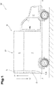
- Fig. 1 10 illustrates a vehicle cabin 10 and a vehicle loading system 100.
- the vehicle cabin 10 comprises a cabin body 11 and a lifting roof 12.
- a movement device 13 is operatively connected to the cabin body 11 and the lifting roof 12.
- the movement device 13 has a first end 14 and a second end 15, the first end 14 being connected to the lifting roof 12 is connected and the second end 15 can be connected to the cabin body 11.
- the movement device 13 further comprises a receptacle 16 at its second end 15.
- the vehicle cabin 10 is shown in a retracted position EP, i.e. the lifting roof 12 is lowered onto the cabin body 11 as far as possible.
- the moving device 13 can be moved in two directions. In the first direction of travel V1, the movement device 13 lifts the lifting roof 12 upwards from the cabin body 11 and thus enlarges an interior space of the vehicle cabin 10. In a second movement direction V2, the movement device 13 lowers the lifting roof 12 onto the cabin body 11 and thus reduces the interior space of the vehicle cabin 10.
- the vehicle cabin 10 is mounted on a carrier vehicle 50 which stands on the ground, the carrier vehicle 50 being in the area of the vehicle cabin 10 below a floor level B.
- the floor level B is a plane in which the underside of the vehicle cabin 10 lies. Any storage of the vehicle cabin 10 (e.g. an intermediate frame) can be considered to be at least partially part of the vehicle cabin 10; the shortest distance to the ground.
- Fig. 2 the vehicle cabin is shown in its extended position AP.
- the lifting roof has been moved in the first direction of displacement V1 by means of the movement device 13 and the interior of the vehicle cabin 10 has thus been enlarged.
- the second end 15 is attached to the cabin body 11 and the first end 14 to the lifting roof 12.
- the first end 14 then moves away from the second end 15 in the first direction of travel V1 and lifts the lifting roof 12 from the cabin body 11.
- the movement device 13 can be implemented, for example, by a hydraulic cylinder, a pneumatic cylinder, a spindle drive or a linear drive.
- Fig. 3 the car is in the retracted position EP and the first end 14 of the movement device 13 has been detached from the lifting roof 12 and attached to the car body 11.
- the movement device 13 is then moved through the floor of the vehicle cabin 10 and below the floor level B until the second end comes into contact with the floor on which the carrier vehicle 50 is standing. Any further movement in the same direction consequently raises the vehicle cabin with respect to the ground and the carrier vehicle 50.
- the movement device 13 can optionally be displaced overall in the second travel direction V2 and thus fastened closer to the floor in the cabin body 11.
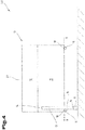
- Fig. 4 the vehicle cabin 10 is shown in a state raised with respect to the ground (only one movement device is shown for the sake of simplicity).
- the movement device 13 At its second end 15, the movement device 13 comprises a support 17 which is connected to the receptacle 16.
- the cabin body 11 comprises rollers 19 which are mounted on roller receptacles 18 and which are below floor level B.
- the carrier vehicle 50 has been driven out from under the vehicle cabin 10.
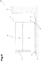
- FIG. 10 shows the vehicle cabin 10 of FIG Fig. 4 being lowered onto rollers 19.
- the vehicle loading system 100 further comprises at least one rail 20, which in Fig. 5 rests with one end on the floor and the other end in a container 60.
- the movement device 13 was compared to the illustration of Fig. 4 again arranged completely within the vehicle cabin 10.
- the vehicle cabin 10 is located in the retracted position EP.
- the vehicle cabin 10 can be pushed into the container 60 via the rail 20 by means of the rollers 19, as shown.
- Fig. 6 shows a comparison of an optional attachment position of the movement device 13 on the vehicle cabin 10.
- the lifting roof 12 is in the extended position AP and the movement device 13 is fastened with its first end to the lifting roof 12 and with its second end 15 on the cabin body 11.
- the lifting roof 12 is in the retracted position EP and the movement device 13 is fastened with its first end to the cabin body 11 and stands with the second end 15 on the floor.
- the different positions of the movement device 13 in the vehicle cabin 10 can thus be clearly seen.
- the travel path of the movement device 13 can be used better and it can be dimensioned smaller and therefore lighter.
- Fig. 7 shows a further embodiment of a rail 20, comprising a straight rail part 21 and an angled rail part 22.
- the straight rail part 21 rests on the floor and the angled rail part 22 on a container 60.
- the two parts 21 and 22 are detachably connected to one another.
- the straight rail part 21 can be used, for example, as a traction aid (for example sand plate) for the carrier vehicle 50, and the angled rail part 22 can be used to prevent the carrier vehicle 50 from rolling away.
- a traction aid for example sand plate
- Fig. 8 shows a further embodiment of a rail 20 in cross section.
- a guide 23 is shown, which on the one hand gives the rail 20 stability (bead) and on the other hand with the rollers 19, for example in FIG Fig. 5 fits together so that the roller 19 is guided in the guide 23 when the vehicle cabin 10 is pushed.
- movement devices for the sake of clarity, only one movement device was shown for the most part.
- multiple movement devices can be provided in a vehicle cabin according to the present disclosure. It For example, two movement devices can be provided which attach to parallel sides of the vehicle cabin or four movement devices which are arranged in the corners of the vehicle cabin or also in the area of the side centers.
Landscapes
- Engineering & Computer Science (AREA)
- Transportation (AREA)
- Mechanical Engineering (AREA)
- Health & Medical Sciences (AREA)
- Public Health (AREA)
- Fittings On The Vehicle Exterior For Carrying Loads, And Devices For Holding Or Mounting Articles (AREA)
Abstract
Die Erfindung betrifft eine Fahrzeugkabine, ein Fahrzeugkabinenverladesystem und Verfahren zur Fahrzeugverladung für Fahrzeuge mit einer Fahrzeugkabine. Die Fahrzeugkabine umfasst einen Kabinenkörper, ein Hubdach und zumindest eine Bewegungseinrichtung. Die Bewegungseinrichtung ist mit dem Kabinenkörper und dem Hubdach so verbunden, dass sie das Hubdach in einer ersten Verfahrrichtung aus einer eingefahrenen Position in eine ausgefahrene Position verfahren kann. Weiterhin ist die Bewegungseinrichtung an einem ersten Ende lösbar mit dem Hubdach verbunden. Die Bewegungseinrichtung ist in einem vom Hubdach gelösten Zustand in einer zweiten Verfahrrichtung, welche entgegengesetzt zur ersten Verfahrrichtung ist, unter ein Bodenniveau der Fahrzeugkabine verfahrbar.The invention relates to a vehicle cabin, a vehicle cabin loading system and a method for vehicle loading for vehicles with a vehicle cabin. The vehicle cabin comprises a cabin body, a lifting roof and at least one movement device. The movement device is connected to the cabin body and the lifting roof in such a way that it can move the lifting roof in a first direction of movement from a retracted position into an extended position. Furthermore, the movement device is releasably connected to the lifting roof at a first end. In a state released from the lifting roof, the movement device can be moved in a second direction of movement, which is opposite to the first direction of movement, below a floor level of the vehicle cabin.
Description
Die vorliegende Erfindung bezieht sich auf ein Fahrzeugverladesystem für eine Fahrzeugkabine mit Hubdach, eine Fahrzeugkabine und ein Verladeverfahren. Im Bereich der Freizeit-, Berufs- oder Militärfahrzeuge kann es wünschenswert sein ein Fahrzeug möglichst kostengünstig und schnell über große Distanzen zu verbringen. Ein kostengünstigstes Verbringungsmittel stellen die verschiedenen Standartcontainer dar.The present invention relates to a vehicle loading system for a vehicle cabin with a lifting roof, a vehicle cabin and a loading method. In the field of recreational, professional or military vehicles, it can be desirable to move a vehicle over long distances as cheaply and quickly as possible. The various standard containers are the most cost-effective means of transport.
Da bei Fahrzeugaufbauten, sogenannten Fahrzeugkabinen oder Fahrzeugkoffern die Außenabmessungen möglichst klein bei möglichst großer Nutzfläche sein sollen, sind Hubdachkoffer seit einigen Jahren bekannt. Bei Fahrt des Fahrzeuges ist das Hubdach in einer eingefahrenen Position und die Fahrzeugkabine ist minimal hoch. Wenn die Fahrzeugkabine verwendet werden soll, wird da Hubdach in seine ausgefahrene Position gebracht und das entstandene zusätzliche Volumen im Innenraum kann genutzt werden.Since the external dimensions of vehicle bodies, so-called vehicle cabins or vehicle cases, should be as small as possible with the largest possible usable area, lifting roof cases have been known for some years. When the vehicle is moving, the lifting roof is in a retracted position and the vehicle cabin is minimally high. When the vehicle cabin is to be used, the lifting roof is brought into its extended position and the additional space created in the interior can be used.
Im Falle einer Verladung des Fahrzeuges zum Zwecke der Verbringung z.B. auf einen anderen Kontinent ist es wünschenswert eine Verladung nur mit Bordmitteln des Fahrzeuges, also ohne zusätzliches Equipment, welches nur zum Verladen gebraucht wird und am Zielort unter Umständen nach dem Ausladen wieder aufwändig gesondert abtransportiert werden muss, durchzuführen.In the case of loading the vehicle for the purpose of transferring it to another continent, for example, it is desirable to only use the vehicle's on-board equipment, i.e. without additional equipment that is only needed for loading and which may, under certain circumstances, be transported separately again at the destination after unloading must perform.
Im Stand der Technik sind einige militärische und zivile Verladesysteme wie das System für den deutsche Militärshelter FMII oder für zivile Reisemobile von der Firma Unicat die Sonderkonstruktion "MD52h" bekannt. Jedoch haben die bekannten Systeme den Nachteil, dass gesondertes Equipment (z.B. Hebevorrichtungen) benötigt wird, um die Ver- und Entladung des Fahrzeugs und das Abnehmen und Aufsetzen der Fahrzeugkabine auf das Trägerfahrzeug durchzuführen.In the prior art, some military and civil loading systems are known, such as the system for the German military shelter FMII or the special design "MD52h" for civilian motorhomes from Unicat. However, the known systems have the disadvantage that separate equipment (e.g. lifting devices) is required in order to carry out the loading and unloading of the vehicle and the removal and placement of the vehicle cabin on the carrier vehicle.
Die vorliegende Anmeldung hat es zur Aufgabe ein Fahrzeugverladesystem für eine Fahrzeugkabine, eine Fahrzeugkabine und ein Verladeverfahren bereit zu stellen, dass eine einfache Verladung mit Bordmitteln ermöglicht. Diese Aufgabe wird durch die beigefügten unabhängigen Ansprüche gelöst.The present application has the task of providing a vehicle loading system for a vehicle cabin, a vehicle cabin and a loading method that a allows easy loading with on-board equipment. This object is achieved by the attached independent claims.
Nach einem Aspekt der vorliegenden Anmeldung umfasst eine Fahrzeugkabine einen Kabinenkörper, ein Hubdach und zumindest eine Bewegungseinrichtung. Die Bewegungseinrichtung ist mit dem Kabinenkörper und dem Hubdach so verbunden, dass sie das Hubdach in einer ersten Verfahrrichtung aus einer eingefahrenen Position in eine ausgefahrene Position verfahren kann. Die Bewegungseinrichtung ist an einem ersten Ende lösbar mit dem Hubdach verbunden. Weiterhin ist die Bewegungseinrichtung in einem vom Hubdach gelösten Zustand in einer zweiten Verfahrrichtung, welche entgegengesetzt zur ersten Verfahrrichtung ist, unter ein Bodenniveau der Fahrzeugkabine verfahrbar. Die kann den Vorteil haben, dass die Bewegungseinrichtung dazu verwendet werden kann das Kabinendach anzuheben und weiterhin zum Anheben der Fahrzeugkabine von einem Trägerfahrzeug verwendet werden kann. Damit kann eine platzsparende Fahrzeugkabine realisiert werden, die selbstverladefähig ist. Die zumindest eine Bewegungseinrichtung kann im Innenraum der Fahrzeugkabine, oder außen an der Fahrzeugkabine angeordnet werden. Auch kann ein Ende der Bewegungseinrichtung im Innenraum der Fahrzeugkabine angeordnet sein und das jeweilig andere Ende außen an der Fahrzeugkabine.According to one aspect of the present application, a vehicle cabin comprises a cabin body, a lifting roof and at least one movement device. The movement device is connected to the cabin body and the lifting roof in such a way that it can move the lifting roof in a first direction of movement from a retracted position into an extended position. The movement device is detachably connected to the lifting roof at a first end. Furthermore, in a state released from the lifting roof, the movement device can be moved in a second direction of movement, which is opposite to the first direction of movement, below a floor level of the vehicle cabin. This can have the advantage that the movement device can be used to raise the cabin roof and can also be used to raise the vehicle cabin from a carrier vehicle. A space-saving vehicle cabin that is self-loading can thus be implemented. The at least one movement device can be arranged in the interior of the vehicle cabin or on the outside of the vehicle cabin. One end of the movement device can also be arranged in the interior of the vehicle cabin and the respective other end on the outside of the vehicle cabin.
Die Bewegungseinrichtung kann mehrfach vorhanden sein, z.B. in jeder der vier Ecken einer in den meisten Fällen quaderförmigen Fahrzeugkabine. Die zumindest eine Bewegungseinrichtung kann weiterhin elektrisch, hydraulisch, pneumatisch angetrieben sein oder eine Kombination davon. Die Bewegungseinrichtung kann z.B. ein doppelt- oder einfachwirkender Zylinder (konventioneller Zylinder) sein oder ein Zylinder mit durchgehender Kolbenstange oder ein elektrisch betriebenes Äquivalent hierzu. Im Falle eines konventionellen Zylinders kann das bewegliche Ende des Zylinders (Kolbenstange) am Hubdach befestigt werden und der Zylinderkörper am Kabinenkörper. Somit kann das Hubdach angehoben werden. Wenn die Fahrzeugkabine angehoben werden soll, dann wird das bewegliche Ende am Kabinenkörper befestigt und der Zylinderkörper vom Kabinenkörper gelöst. Ausfahren der Kolbenstange bewirkt nun ein Verfahren des Zylinderkörpers unter das Bodenniveau der Kabine und durch Aufstehen auf dem Boden letztendlich ein Anheben der Fahrzeugkabine. Dies gilt mutatis mutandis für Zylinder mit durchgehender Kolbenstange, wobei hier ggf. der Zylinderkörper für das Anheben der Fahrzeugkabine nicht vom Kabinenkörper gelöst werden muss. Bei Spindel- oder Linearantrieben gilt voran genanntes entsprechend.The movement device can be present several times, for example in each of the four corners of a vehicle cabin, which in most cases is cuboid. The at least one movement device can furthermore be driven electrically, hydraulically, pneumatically or a combination thereof. The movement device can be, for example, a double-acting or single-acting cylinder (conventional cylinder) or a cylinder with a continuous piston rod or an electrically operated equivalent. In the case of a conventional cylinder, the movable end of the cylinder (piston rod) can be attached to the lifting roof and the cylinder body to the cabin body. This means that the pop-up roof can be raised. When the vehicle cabin is to be raised, the movable end is attached to the cabin body and the cylinder body is detached from the cabin body. Extending the piston rod causes the cylinder body to move below the floor level of the cabin and, by standing on the floor, ultimately lifts the vehicle cabin. this applies mutatis mutandis for cylinders with a continuous piston rod, whereby the cylinder body for lifting the vehicle cabin may not have to be detached from the cabin body. The above applies accordingly to spindle or linear drives.
Bei einer Fahrzeugkabine nach einem weiteren Aspekt weist die Bewegungseinrichtung an einem zweiten Ende, welches gegenüberliegend dem ersten Ende ist, eine Aufnahme auf. Dies kann den Vorteil haben, dass an die Bewegungseinrichtung Anbauten angebracht werden können, um den Verladevorgang zu vereinfachen.In a vehicle cabin according to a further aspect, the movement device has a receptacle at a second end, which is opposite the first end. This can have the advantage that attachments can be attached to the movement device in order to simplify the loading process.
Eine Fahrzeugkabine nach einem weiteren Aspekt umfasst weiterhin Stützen, welche dazu vorgesehen sind an die Aufnahme angebracht zu werden. Dies kann den Vorteil haben, dass der Verfahrweg reduziert werden kann, welcher für das Anheben von einem Trägerfahrzeug notwendig ist und die Bewegungseinrichtung so kleiner und leichter dimensioniert werden kann. Die Stützen können weiterhin so geformt sein, dass sie nach außen in Bezug auf eine senkrecht und längs (parallel zur Fahrtrichtung) mittig durch die Kabine verlaufende Ebene (Längsmittelebene) auskragen. Dies kann von Vorteil sein, da z.B. bei einem Ausfahren des Trägerfahrzeugs unter der an vier Ecken angehobenen Fahrzeugkabine möglicherweise die Hinterachse(n) des Trägerfahrzeugs ohne die auskragenden Stützen nicht durch den Abstand des vorderen Stützenpaares hindurchpassen würde(n), da Fahrzeugkabinen selten sehr viel breiter sind, als die Achsweite(n) der Hinterachse(n), d.h. ein seitlicher Überhang der Fahrzeugkabine in Bezug auf die Achsweite(n) gering bis nicht vorhanden ist und daher bei abgesenkten Bewegungseinrichtung nicht ausreichend Platz für die Durchfahrt der Achse(n) gegeben sein kann.A vehicle cabin according to a further aspect further comprises supports which are provided to be attached to the receptacle. This can have the advantage that the travel path which is necessary for lifting a carrier vehicle can be reduced and the movement device can thus be dimensioned smaller and lighter. The supports can furthermore be shaped in such a way that they protrude outwards in relation to a plane (longitudinal center plane) running vertically and longitudinally (parallel to the direction of travel) centrally through the cabin. This can be advantageous because, for example, when the carrier vehicle is extended under the vehicle cabin raised at four corners, the rear axle (s) of the carrier vehicle without the cantilevered supports would possibly not fit through the distance between the front pair of supports, since the vehicle cabs rarely have a great deal of space are wider than the axle width (s) of the rear axle (s), i.e. a lateral overhang of the vehicle cabin in relation to the axle width (s) is small or nonexistent and therefore not enough space for the axle (s) to pass through when the movement device is lowered can be given.
Eine Fahrzeugkabine nach einem weiteren Aspekt umfasst weiterhin Rollenaufnahmen, welche dazu vorgesehen und geeignet sind, dass Rollen an die Rollenaufnahmen befestigt werden können und in einem montierten Zustand über das Bodenniveau nach unten hinausstehen. Wahlweise kann die Fahrzeugkabine fest verbaute Rollen oder versenkbare (in den Innenraum der Fahrzeugkabine) Rollen aufweisen. Die Rollenaufnahmen oder an die Fahrzeugkabine befestigten Rollen können entsprechende Abdeckungen aufweisen, die für den Einsatz der Rollen entfernt werden können. Dies kann den Vorteil haben, dass ein Verladen der Fahrzeugkabine erleichtert wird.A vehicle cabin according to a further aspect further comprises roller receptacles, which are provided and suitable for rollers to be fastened to the roller receptacles and, in an assembled state, protrude downwards above the floor level. The vehicle cabin can optionally have built-in castors or castors that can be retracted (into the interior of the vehicle cabin). The roller mounts or rollers attached to the vehicle cabin can have corresponding covers that are suitable for the Use of the rollers can be removed. This can have the advantage that loading the vehicle cabin is made easier.
Bei einer Fahrzeugkabine nach einem weiteren Aspekt kann die zumindest eine Bewegungseinrichtung parallel zu den beiden Verfahrrichtungen in zumindest zwei unterschiedlichen Positionen an den Kabinenkörper angebracht werden. Dies kann den Vorteil haben, dass jeweils der notwendige Verfahrweg verkürzt werden kann, wenn die Bewegungseinrichtung parallel zu den beiden Verfahrrichtungen versetzt wird. Damit kann die Bewegungseinrichtung kleiner dimensioniert werden.In a vehicle cabin according to a further aspect, the at least one movement device can be attached to the cabin body in at least two different positions parallel to the two directions of travel. This can have the advantage that the necessary travel path can be shortened if the movement device is offset parallel to the two travel directions. The movement device can thus be made smaller.
Ein Fahrzeugverladesystem nach einem weiteren Aspekt umfasst eine Fahrzeugkabine nach einem der obigen Aspekte, Schienen und Rollen. Die Rollen sind dazu vorgesehen an entsprechende Aufnahmen an der Fahrzeugkabine angebracht zu werden. Die Schienen weisen eine Führung auf, die dazu vorgesehen ist mit den Rollen in Eingriff gebracht zu werden. Dies kann den Vorteil haben, dass die Fahrzeugkabine auf die angebrachten Rollen abgesetzt zu werden und über die Schienen verladen zu werden. Dies kann z.B. das Einbringen in einen Container oder auf eine sonstige Logistikplattform sein und die Schienen können dazu verwendet werden, die Fahrzeugkabine über den Niveauunterschied zwischen Containerboden und seiner Stellfläche zu überwinden. Die Schienen können in platzsparend in Halterungen an der Fahrzeugkabine oder einem Trägerfahrzeug verbaut werden. Ein Container im Sinne dieser Anmeldung kann jegliches Behältnis sein, das genug Innenraum bietet, um das Fahrzeugverladesystem unterzubringen.A vehicle loading system according to a further aspect comprises a vehicle cabin according to one of the above aspects, rails and rollers. The rollers are intended to be attached to corresponding receptacles on the vehicle cabin. The rails have a guide which is intended to be brought into engagement with the rollers. This can have the advantage that the vehicle cabin can be set down on the attached rollers and loaded over the rails. This can be, for example, placing in a container or on another logistics platform and the rails can be used to overcome the vehicle cabin via the difference in level between the container floor and its floor space. The rails can be installed in brackets on the vehicle cabin or a carrier vehicle to save space. A container within the meaning of this application can be any receptacle that offers enough interior space to accommodate the vehicle loading system.
Bei einem Fahrzeugverladesystem nach einem weiteren Aspekt sind die Schienen als Traktionshilfen ausgebildet, welche die Führung aufweisen. Traktionshilfen können z.B. Sandbleche mit einer für die Rollen passenden Führung sein. Dies kann den Vorteil haben, dass die Traktionshilfen einen Doppelnutzen haben.In a vehicle loading system according to a further aspect, the rails are designed as traction aids which have the guide. Traction aids can be, for example, sand sheets with a guide suitable for the rollers. This can have the advantage that the traction aids have a double use.
Bei einem Fahrzeugverladesystem nach einem weiteren Aspekt sind die Schienen mehrteilig (z.B. ein gerader Schienenteil und ein gewinkelter Schienenteil) und ein Teil (z.B. der gewinkelte Schienenteil) ist als Fahrzeugwegrollsicherung vorgesehen und geeignet. Dies kann den Vorteil haben, dass die Schienen abgewinkelt verlaufen können und so ein besseres Verladen in z.B. einen Standartcontainer ermöglichen, weil die Schienen einen im Verhältnis längeren Teil aufweisen können, der für die Überwindung des Niveauunterschiedes zwischen dem Containerboden und seiner Stellfläche verwendet werden kann und einem abgewinkelten, im Verhältnis kürzeren Teil, der z.B. waagerecht auf den Containerboden aufgelegt werden kann und das Einbringen der Fahrzeugkabine in den Container erleichtert. Die Teile der Schiene können lösbar verbunden werden und so getrennt verstaut und der gewinkelte Teil z.B. als Wegrollsicherung für ein Trägerfahrzeug (Unterlegkeil) verwendet werden.In a vehicle loading system according to a further aspect, the rails are in several parts (eg a straight rail part and an angled rail part) and one part (eg the angled rail part) is intended and suitable as a vehicle roll-away protection. this can have the advantage that the rails can be angled and thus enable better loading into, for example, a standard container, because the rails can have a relatively longer part that can be used to overcome the level difference between the container floor and its footprint and a angled, relatively shorter part, which can be placed horizontally on the container floor, for example, and which makes it easier to bring the vehicle cabin into the container. The parts of the rail can be detachably connected and stowed away separately and the angled part can be used, for example, to prevent a carrier vehicle from rolling away (wheel chock).
Bei einem Fahrzeugverladesystem nach einem weiteren Aspekt können die Stützen in einem Fahrzeugfahrzustand (d.h. das Trägerfahrzeug wird mit Fahrzeugkabine im Straßenverkehr bewegt) an das Trägerfahrzeug montiert werden. Dies kann den Vorteil haben, dass sie z.B. in Astabweiser oder Gepäckträger der Fahrzeugkabine und/oder des Trägerfahrzeugs integriert werden können und damit einen Doppelnutzen haben.In a vehicle loading system according to a further aspect, the supports can be mounted on the carrier vehicle in a vehicle driving state (i.e. the carrier vehicle is moved with the vehicle cabin in traffic). This can have the advantage that they can be integrated into branch deflectors or luggage racks in the vehicle cabin and / or the carrier vehicle, for example, and thus have a double use.
Ein Verfahren zur Fahrzeugverladung für Fahrzeuge mit einer Fahrzeugkabine nach einem weiteren Aspekt umfasst die folgenden Schritte:
- Verfahren eins Hubdachs einer Fahrzeugkabine vermittels zumindest einer Bewegungseinrichtung in einer zweiten Verfahrrichtung (Hubdach-Absenkrichtung) in eine eingefahrene Position;
- Lösen eines ersten Endes der Bewegungseinrichtung vom Hubdach;
- Verfahren der Bewegungseinrichtung in der zweiten Verfahrrichtung, sodass sich ein zweites Ende, welches dem ersten Ende gegenüberliegt unter ein Bodenniveau bewegt;
- Lösen der Fahrzeugkabine von einem Trägerfahrzeug;
- Abheben der Fahrzeugkabine vom Trägerfahrzeug durch Verfahren der Bewegungseinrichtung in der zweiten Richtung, sodass das zweite Ende in Kontakt mit dem Boden kommt;
- Ausfahren des Trägerfahrzeugs unter der Fahrzeugkabine;
- Absenken der Fahrzeugkabine durch Verfahren der Bewegungseinrichtung in einer ersten Verfahrrichtung entgegengesetzt zur zweiten Verfahrrichtung;
- Verladen der Fahrzeugkabine und des Trägerfahrzeugs in einen Container.
- Moving a lifting roof of a vehicle cabin by means of at least one movement device in a second direction of travel (lifting roof lowering direction) into a retracted position;
- Releasing a first end of the movement device from the lifting roof;
- Moving the movement device in the second direction of movement, so that a second end, which is opposite the first end, moves below ground level;
- Releasing the vehicle cabin from a carrier vehicle;
- Lifting the vehicle cabin from the carrier vehicle by moving the movement device in the second direction so that the second end comes into contact with the ground;
- Extending the carrier vehicle under the vehicle cabin;
- Lowering the vehicle cabin by moving the movement device in a first direction of movement opposite to the second direction of movement;
- Loading the vehicle cabin and the carrier vehicle into a container.
Bei einem Verfahren nach einem weiteren Aspekt wird im Schritt des Absenkens der Fahrzeugkabine, die Fahrzeugkabine auf Rollen abgesenkt, welche über das Bodenniveau hinausstehen. Dies kann den Vorteil haben, dass die Fahrzeugkabine einfach verschoben werden kann.In a method according to a further aspect, in the step of lowering the vehicle cabin, the vehicle cabin is lowered on rollers which protrude above the floor level. This can have the advantage that the vehicle cabin can easily be moved.
Bei einem Verfahren nach einem weiteren Aspekt wird im Schritt des Verladens das Trägerfahrzeug und die Fahrzeugkabine die Rollen in Eingriff mit Schienen gebracht. Dabei weisen die Schienen eine Führung für die Rollen auf und die Fahrzeugkabine wird mit Hilfe der Schienen in den Container verladen. Dies kann den Vorteil haben, dass die Schienen einfach am Trägerfahrzeug und/oder der Fahrzeugkabine befestigt werden können.In a method according to a further aspect, in the step of loading the carrier vehicle and the vehicle cabin, the rollers are brought into engagement with rails. The rails have a guide for the rollers and the vehicle cabin is loaded into the container with the aid of the rails. This can have the advantage that the rails can easily be attached to the carrier vehicle and / or the vehicle cabin.
Bei einem Verfahren nach einem weiteren Aspekt schiebt im Schritt des Verladens das Trägerfahrzeug die Fahrzeugkabine in den Container. Dies kann den Vorteil haben, dass der Verladevorgang vereinfacht wird.In a method according to a further aspect, the carrier vehicle pushes the vehicle cabin into the container in the loading step. This can have the advantage that the loading process is simplified.
Bei einem Verfahren nach einem weiteren Aspekt werden die Rollen vor dem Absenken an die Fahrzeugkabine angebracht. Dies kann den Vorteil haben, dass die Rollen nur für diesen Einsatz an die Fahrzeugkabine angebracht werden und nicht ständig Außeneinflüssen ausgesetzt sind.In a method according to a further aspect, the rollers are attached to the vehicle cabin prior to lowering. This can have the advantage that the rollers are only attached to the vehicle cabin for this purpose and are not constantly exposed to external influences.
Bei einem Verfahren nach einem weiteren Aspekt wird zwischen dem Schritt des Lösens des ersten Endes und dem Schritt des Anhebens der Fahrzeugkabine die Bewegungseinrichtung von einer Position in eine andere Position an einem Kabinenkörper der Fahrzeugkabine montiert. Dies kann den Vorteil haben, dass die Bewegungsrichtung somit in der jeweilig notwendigen Verfahrrichtung versetzt wird und weniger Weg für den jeweiligen Schritt (Anheben des Hubdaches oder Anheben der Kabine) benötigt. Somit kann die Bewegungsrichtung kleiner und leichter dimensioniert und der Verladevorgang verkürzt werden.In a method according to a further aspect, between the step of releasing the first end and the step of lifting the vehicle cabin, the movement device from one position to another position is mounted on a cabin body of the vehicle cabin. This can have the advantage that the direction of movement is offset in the respective necessary direction of travel and requires less travel for the respective step (raising the lifting roof or raising the cabin). Thus, the direction of movement can be made smaller and lighter and the loading process can be shortened.
Zum besseren Verständnis der Erfindung wird diese anhand der nachfolgenden Figuren näher erläutert. Es zeigen jeweils in stark vereinfachter, schematischer Darstellung:
-
Fig. 1 ein Ausführungsbeispiel eines Trägerfahrzeugs mit einem Ausführungsbeispiel einer Fahrzeugkabine mit Hubdach im eingefahrenen Zustand. -
Fig. 2 das Ausführungsbeispiel derFig. 1 , wobei die Fahrzeugkabine in einem ausgefahrenen Zustand befindlich ist. -
Fig. 3 das Ausführungsbeispiel derFiguren. 1 und2 , wobei die Fahrzeugkabine in einem eingefahrenen Zustand befindlich ist und eine Bewegungseinrichtung auf den Boden abgesenkt dargestellt ist. -
Fig. 4 das Ausführungsbeispiel der Fahrzeugkabine derFiguren 1 bis 3 , wobei die Fahrzeugkabine durch die Bewegungseinrichtung abgestützt ist. -
Fig. 5 das Verladen der Fahrzeugkabine in einen Container. -
Fig. 6 die unterschiedlichen Positionen der Bewegungseinrichtung einer Fahrzeugkabine nach dem Ausführungsbeispiel derFiguren 1 bis 3 . -
Fig. 7 ein Ausführungsbeispiel einer an einen Container angelegten Schiene. -
Fig. 8 ein Ausführungsbeispiel einer Schiene im Querschnitt.
-
Fig. 1 an embodiment of a carrier vehicle with an embodiment of a vehicle cabin with a lifting roof in the retracted state. -
Fig. 2 the embodiment ofFig. 1 , wherein the vehicle cabin is in an extended state. -
Fig. 3 the embodiment ofCharacters. 1 and2 , wherein the vehicle cabin is in a retracted state and a movement device is shown lowered to the floor. -
Fig. 4 the embodiment of the vehicle cabin ofFigures 1 to 3 , wherein the vehicle cabin is supported by the movement device. -
Fig. 5 loading the vehicle cabin into a container. -
Fig. 6 the different positions of the movement device of a vehicle cabin according to the embodiment of FIGFigures 1 to 3 . -
Fig. 7 an embodiment of a rail applied to a container. -
Fig. 8 an embodiment of a rail in cross section.
Einführend sei festgehalten, dass in den unterschiedlich beschriebenen Ausführungsformen gleiche Teile mit gleichen Bezugszeichen bzw. gleichen Bauteilbezeichnungen versehen werden, wobei die in der gesamten Beschreibung enthaltenen Offenbarungen sinngemäß auf (funktions-)gleiche Teile mit gleichen Bezugszeichen bzw. gleichen Bauteilbezeichnungen übertragen werden können. Auch sind die in der Beschreibung gewählten Lageangaben, wie z.B. oben, unten, seitlich usw. auf die unmittelbar beschriebene sowie dargestellte Figur bezogen bzw. auf ein Fahrzeug auf einer horizontalen Ebene stehend und sind diese Lageangaben bei einer Lageänderung sinngemäß auf die neue Lage zu übertragen. Im Hinblick auf die folgende detaillierte Beschreibung der Figuren wird sowohl eine Fahrzeugkabine, ein Fahrzeugverladesystem und ein Verfahren zur Fahrzeugverladung für Fahrzeuge mit einer Fahrzeugkabine beschrieben. Die Verfahrensschritte sind in die Vorrichtungsbeschreibung eingeflochten.By way of introduction, it should be noted that in the differently described embodiments, the same parts are provided with the same reference symbols or the same component designations, whereby the disclosures contained in the entire description can be transferred accordingly to (functionally) identical parts with the same reference symbols or the same component designations. The position details chosen in the description, such as above, below, to the side, etc., refer to the figure immediately described and shown or to a vehicle standing on a horizontal plane and these position details are to be transferred accordingly to the new position in the event of a change in position . In terms of The following detailed description of the figures describes both a vehicle cabin, a vehicle loading system and a method for vehicle loading for vehicles with a vehicle cabin. The process steps are woven into the device description.
Anfänglich wird Bezug genommen auf
Die Fahrzeugkabine 10 ist in einer eingefahrenen Position EP dargestellt, d.h. das Hubdach 12 ist soweit als möglich auf den Kabinenkörper 11 abgesenkt. Die Bewegungseinrichtung 13 kann in zwei Richtungen bewegt werden. In der ersten Verfahrrichtung V1 hebt die Bewegungseinrichtung 13 das Hubdach 12 vom Kabinenkörper 11 nach oben und vergrößert so einen Innenraum der Fahrzeugkabine 10. In einer zweiten Verfahrrichtung V2 senkt die Bewegungseinrichtung 13 das Hubdach 12 auf den Kabinenkörper 11 ab und verkleinert so den Innenraum der Fahrzeugkabine 10.The
Die Fahrzeugkabine 10 ist auf ein Trägerfahrzeug 50 montiert, welches auf dem Boden steht, wobei sich das Trägerfahrzeug 50 im Bereich der Fahrzeugkabine 10 unter einem Bodenniveau B befindet. Das Bodenniveau B ist eine Ebene, in welcher die Unterseite der Fahrzeugkabine 10 liegt. Eine etwaige Lagerung der Fahrzeugkabine 10 (z.B. ein Zwischenrahmen) kann zumindest teilweise zur Fahrzeugkabine 10 gehörend betrachtet werden, das Bodenniveau B verläuft in diesem Fall horizontal durch den oder die tiefsten Punkte der Fahrzeugkabine 10, d.h. den/die Punkt(e), die den kürzesten Abstand zum Boden haben.The
In
In
In
In den vorangegangenen Beispielen wurde der Übersichtlichkeit überwiegend lediglich eine Bewegungseinrichtung dargestellt. Jedoch können mehrere Bewegungseinrichtungen in einer Fahrzeugkabine gemäß der vorliegenden Offenbarung vorgesehen werden. Es können z.B. zwei Bewegungseinrichtungen vorgesehen sein, welche an parallelen Seiten der Fahrzeugkabine ansetzen oder vier Bewegungseinrichtungen, welche in den Ecken der Fahrzeugkabine oder auch im Bereich der Seitenmitten angeordnet sind.In the preceding examples, for the sake of clarity, only one movement device was shown for the most part. However, multiple movement devices can be provided in a vehicle cabin according to the present disclosure. It For example, two movement devices can be provided which attach to parallel sides of the vehicle cabin or four movement devices which are arranged in the corners of the vehicle cabin or also in the area of the side centers.
Die Ausführungsbeispiele zeigen mögliche Ausführungsvarianten, wobei an dieser Stelle bemerkt sei, dass die Erfindung nicht auf die speziell dargestellten Ausführungsvarianten der-selben eingeschränkt ist, sondern vielmehr auch diverse Kombinationen der einzelnen Ausführungsvarianten untereinander möglich sind und diese Variationsmöglichkeit aufgrund der Lehre zum technischen Handeln durch gegenständliche Erfindung im Können des auf diesem technischen Gebiet tätigen Fachmannes liegt.The exemplary embodiments show possible design variants, whereby it should be noted at this point that the invention is not restricted to the specifically illustrated design variants of the same, but rather various combinations of the individual design variants with one another are possible and this possibility of variation is possible due to the teaching on technical action through objective Invention is within the skill of those skilled in the art.
Der Schutzbereich ist durch die Ansprüche bestimmt. Die Beschreibung und die Zeichnungen sind jedoch zur Auslegung der Ansprüche heranzuziehen. Einzelmerkmale oder Merkmals-kombinationen aus den gezeigten und beschriebenen unterschiedlichen Ausführungsbeispielen können für sich eigenständige erfinderische Lösungen darstellen. Die den eigenständigen erfinderischen Lösungen zugrundeliegende Aufgabe kann der Beschreibung entnommen werden.The scope of protection is determined by the claims. However, the description and the drawings are to be used to interpret the claims. Individual features or combinations of features from the different exemplary embodiments shown and described can represent independent inventive solutions. The task on which the independent inventive solutions are based can be found in the description.
Sämtliche Angaben zu Wertebereichen in gegenständlicher Beschreibung sind so zu verstehen, dass diese beliebige und alle Teilbereiche daraus mitumfassen, z.B. ist die Angabe 1 bis 10 so zu verstehen, dass sämtliche Teilbereiche, ausgehend von der unteren Grenze 1 und der oberen Grenze 10 mit umfasst sind, d.h. sämtliche Teilbereiche beginnen mit einer unteren Grenze von 1 oder größer und enden bei einer oberen Grenze von 10 oder weniger, z.B. 1 bis 1,7, oder 3,2 bis 8,1, oder 5,5 bis 10.All information on value ranges in the present description are to be understood in such a way that they include any and all sub-areas thereof, e.g. the information 1 to 10 is to be understood in such a way that all sub-areas, starting from the lower limit 1 and the
Der Ordnung halber sei abschließend darauf hingewiesen, dass zum besseren Verständnis des Aufbaus Elemente teilweise unmaßstäblich und/oder vergrößert und/oder verkleinert dargestellt wurden.For the sake of clarity, it should finally be pointed out that, for a better understanding of the structure, some elements have been shown not to scale and / or enlarged and / or reduced.
- 1010
- FahrzeugkabineVehicle cabin
- 1111th
- KabinenkörperCabin body
- 1212th
- HubdachLifting roof
- 1313th
- BewegungseinrichtungMovement device
- 1414th
- erstes Endefirst end
- 1515th
- zweites Endesecond end
- 1616
- Aufnahmerecording
- 1717th
- StützenSupport
- 1818th
- RollenaufnahmenRoll mounts
- 1919th
- Rollenroll
- 2020th
- Schienenrails
- 2121
- gerader Schienenteilstraight rail part
- 2222nd
- gewinkelter Schienenteilangled rail part
- 2323
- Führungguide
- 5050
- TrägerfahrzeugCarrier vehicle
- 6060
- ContainerContainer
- 100100
- FahrzeugverladesystemVehicle loading system
- BB.
- BodenniveauGround level
- V1V1
- erste Verfahrrichtungfirst direction of travel
- V2V2
- zweite Verfahrrichtungsecond direction of travel
- EPEP
- eingefahrenen Positionretracted position
- APAP
- ausgefahrene Positionextended position
Claims (15)
Applications Claiming Priority (1)
| Application Number | Priority Date | Filing Date | Title |
|---|---|---|---|
| LU101795A LU101795B1 (en) | 2020-05-13 | 2020-05-13 | Vehicle loading system for a vehicle cabin |
Publications (3)
| Publication Number | Publication Date |
|---|---|
| EP3909808A1 true EP3909808A1 (en) | 2021-11-17 |
| EP3909808C0 EP3909808C0 (en) | 2023-12-13 |
| EP3909808B1 EP3909808B1 (en) | 2023-12-13 |
Family
ID=70922098
Family Applications (1)
| Application Number | Title | Priority Date | Filing Date |
|---|---|---|---|
| EP21020150.5A Active EP3909808B1 (en) | 2020-05-13 | 2021-03-15 | Vehicle loading system for a vehicle cabin |
Country Status (2)
| Country | Link |
|---|---|
| EP (1) | EP3909808B1 (en) |
| LU (1) | LU101795B1 (en) |
Citations (5)
| Publication number | Priority date | Publication date | Assignee | Title |
|---|---|---|---|---|
| DE69120035T2 (en) * | 1990-12-06 | 1996-12-19 | Lohr Ind | Residential container with a stretchable interior |
| US6322127B1 (en) * | 1997-04-07 | 2001-11-27 | Patrick Masterson | Tractor trailer cover assembly |
| DE10104529A1 (en) * | 2001-01-31 | 2002-08-01 | Unicat Fahrzeugbau Gmbh | Expedition vehicle, motor caravan, or similar has body with lower body section and roof raised by lifting devices, and intermediate heated seals |
| EA016689B1 (en) * | 2010-04-21 | 2012-06-29 | Общество С Ограниченной Ответственностью "Мидивисана" | The device and way of formation of rooms fromthe body-container of variable volume |
| US9302605B1 (en) * | 2013-03-04 | 2016-04-05 | Michael Van Pelt | Expedition vehicle |
-
2020
- 2020-05-13 LU LU101795A patent/LU101795B1/en active IP Right Grant
-
2021
- 2021-03-15 EP EP21020150.5A patent/EP3909808B1/en active Active
Patent Citations (5)
| Publication number | Priority date | Publication date | Assignee | Title |
|---|---|---|---|---|
| DE69120035T2 (en) * | 1990-12-06 | 1996-12-19 | Lohr Ind | Residential container with a stretchable interior |
| US6322127B1 (en) * | 1997-04-07 | 2001-11-27 | Patrick Masterson | Tractor trailer cover assembly |
| DE10104529A1 (en) * | 2001-01-31 | 2002-08-01 | Unicat Fahrzeugbau Gmbh | Expedition vehicle, motor caravan, or similar has body with lower body section and roof raised by lifting devices, and intermediate heated seals |
| EA016689B1 (en) * | 2010-04-21 | 2012-06-29 | Общество С Ограниченной Ответственностью "Мидивисана" | The device and way of formation of rooms fromthe body-container of variable volume |
| US9302605B1 (en) * | 2013-03-04 | 2016-04-05 | Michael Van Pelt | Expedition vehicle |
Also Published As
| Publication number | Publication date |
|---|---|
| LU101795B1 (en) | 2021-11-15 |
| EP3909808C0 (en) | 2023-12-13 |
| EP3909808B1 (en) | 2023-12-13 |
Similar Documents
| Publication | Publication Date | Title |
|---|---|---|
| EP2151403B1 (en) | Logistics system | |
| DE2029636A1 (en) | Transfer device | |
| DE102014007539A1 (en) | Apparatus and method for picking load carriers, in particular small load carriers | |
| DE102007032056A1 (en) | Trailer for retaining roll container in industrial truck, has container retainer lifted and lowered by lifting unit, saddle coupling coupled with self-supporting, rigid front frame, and front sided saddle plate connected with frame | |
| EP0733003B1 (en) | Vehicle with superstructure | |
| DE102019002569A1 (en) | Chassis for a vehicle and method of attaching a structure to a chassis | |
| DE102017102930B4 (en) | Lifting device and system for transporting general cargo | |
| DE102004018910A1 (en) | Trailer for use at airport or in factory, comprising lifting and lowering unit for transported goods | |
| DE202004015422U1 (en) | Positioning system for an overhead working vehicle, e.g. for use in aircraft maintenance, comprises a lower carrying vehicle, lifting arrangement, base plate and coupling arrangements for raising and lowering a tool or platform | |
| EP1840056A1 (en) | Device for loading and unloading a filler device transversely to the direction of transport | |
| EP3909808B1 (en) | Vehicle loading system for a vehicle cabin | |
| EP3390148A1 (en) | Transport vehicle for containers | |
| CH624361A5 (en) | Device for loading and unloading a road-bound or rail-bound vehicle | |
| DE3123791A1 (en) | METHOD AND DEVICE FOR HANDLING AND TRANSPORTING, IN PARTICULAR BETWEEN A RO-RO SHIP AND A TERMINAL - A UNIT LOAD THAT CONSTITUTES ONE OR MORE CONTAINERS OR THE LIKE | |
| EP2108605A1 (en) | Device for transporting a container | |
| EP3293048A1 (en) | Loading platform | |
| DE2802267A1 (en) | TRUCK FOR TRANSPORTING VEHICLES, IN PARTICULAR MEDIUM AND HEAVY INDUSTRIAL VEHICLES | |
| DE29606845U1 (en) | Subframe for a truck for the transport of swap bodies | |
| EP3296175B1 (en) | Method for transporting a semitrailer | |
| DE102015001362A1 (en) | Method and system for positioning swap bodies | |
| DE102018122318A1 (en) | Carriage for a transport vehicle for transporting roll containers | |
| DE102012108527B4 (en) | Truck with a protective frame | |
| DE102014107334B4 (en) | Charging system for a vehicle | |
| DE2936160A1 (en) | Heavy weight lorry loading installation - uses loading machine equipped with conveyor consisting of load carriers and auxiliary sliders | |
| EP0464241A1 (en) | Vehicle for transporting other vehicles |
Legal Events
| Date | Code | Title | Description |
|---|---|---|---|
| PUAI | Public reference made under article 153(3) epc to a published international application that has entered the european phase |
Free format text: ORIGINAL CODE: 0009012 |
|
| STAA | Information on the status of an ep patent application or granted ep patent |
Free format text: STATUS: REQUEST FOR EXAMINATION WAS MADE |
|
| 17P | Request for examination filed |
Effective date: 20210412 |
|
| AK | Designated contracting states |
Kind code of ref document: A1 Designated state(s): AL AT BE BG CH CY CZ DE DK EE ES FI FR GB GR HR HU IE IS IT LI LT LU LV MC MK MT NL NO PL PT RO RS SE SI SK SM TR |
|
| B565 | Issuance of search results under rule 164(2) epc |
Effective date: 20210429 |
|
| GRAP | Despatch of communication of intention to grant a patent |
Free format text: ORIGINAL CODE: EPIDOSNIGR1 |
|
| STAA | Information on the status of an ep patent application or granted ep patent |
Free format text: STATUS: GRANT OF PATENT IS INTENDED |
|
| RIC1 | Information provided on ipc code assigned before grant |
Ipc: B60J 7/16 20060101ALN20220923BHEP Ipc: B60J 7/04 20060101ALN20220923BHEP Ipc: B65D 90/00 20060101ALN20220923BHEP Ipc: B65D 90/18 20060101ALN20220923BHEP Ipc: B65D 90/14 20060101ALN20220923BHEP Ipc: B60P 1/52 20060101ALN20220923BHEP Ipc: B60P 3/34 20060101ALI20220923BHEP Ipc: B60P 1/64 20060101AFI20220923BHEP |
|
| RIC1 | Information provided on ipc code assigned before grant |
Ipc: B60J 7/16 20060101ALN20220930BHEP Ipc: B60J 7/04 20060101ALN20220930BHEP Ipc: B65D 90/00 20060101ALN20220930BHEP Ipc: B65D 90/18 20060101ALN20220930BHEP Ipc: B65D 90/14 20060101ALN20220930BHEP Ipc: B60P 1/52 20060101ALN20220930BHEP Ipc: B60P 3/34 20060101ALI20220930BHEP Ipc: B60P 1/64 20060101AFI20220930BHEP |
|
| INTG | Intention to grant announced |
Effective date: 20221020 |
|
| GRAJ | Information related to disapproval of communication of intention to grant by the applicant or resumption of examination proceedings by the epo deleted |
Free format text: ORIGINAL CODE: EPIDOSDIGR1 |
|
| STAA | Information on the status of an ep patent application or granted ep patent |
Free format text: STATUS: REQUEST FOR EXAMINATION WAS MADE |
|
| INTC | Intention to grant announced (deleted) | ||
| RIC1 | Information provided on ipc code assigned before grant |
Ipc: B60J 7/16 20060101ALN20230222BHEP Ipc: B60J 7/04 20060101ALN20230222BHEP Ipc: B65D 90/00 20060101ALN20230222BHEP Ipc: B65D 90/18 20060101ALN20230222BHEP Ipc: B65D 90/14 20060101ALN20230222BHEP Ipc: B60P 1/52 20060101ALN20230222BHEP Ipc: B60P 3/34 20060101ALI20230222BHEP Ipc: B60P 1/64 20060101AFI20230222BHEP |
|
| GRAP | Despatch of communication of intention to grant a patent |
Free format text: ORIGINAL CODE: EPIDOSNIGR1 |
|
| STAA | Information on the status of an ep patent application or granted ep patent |
Free format text: STATUS: GRANT OF PATENT IS INTENDED |
|
| INTG | Intention to grant announced |
Effective date: 20230324 |
|
| INTG | Intention to grant announced |
Effective date: 20230331 |
|
| GRAS | Grant fee paid |
Free format text: ORIGINAL CODE: EPIDOSNIGR3 |
|
| GRAA | (expected) grant |
Free format text: ORIGINAL CODE: 0009210 |
|
| STAA | Information on the status of an ep patent application or granted ep patent |
Free format text: STATUS: THE PATENT HAS BEEN GRANTED |
|
| AK | Designated contracting states |
Kind code of ref document: B1 Designated state(s): AL AT BE BG CH CY CZ DE DK EE ES FI FR GB GR HR HU IE IS IT LI LT LU LV MC MK MT NL NO PL PT RO RS SE SI SK SM TR |
|
| REG | Reference to a national code |
Ref country code: GB Ref legal event code: FG4D Free format text: NOT ENGLISH |
|
| REG | Reference to a national code |
Ref country code: CH Ref legal event code: EP |
|
| REG | Reference to a national code |
Ref country code: DE Ref legal event code: R096 Ref document number: 502021002142 Country of ref document: DE |
|
| REG | Reference to a national code |
Ref country code: IE Ref legal event code: FG4D Free format text: LANGUAGE OF EP DOCUMENT: GERMAN |
|
| U01 | Request for unitary effect filed |
Effective date: 20240115 |
|
| U07 | Unitary effect registered |
Designated state(s): AT BE BG DE DK EE FI FR IT LT LU LV MT NL PT SE SI Effective date: 20240124 |
|
| PG25 | Lapsed in a contracting state [announced via postgrant information from national office to epo] |
Ref country code: GR Free format text: LAPSE BECAUSE OF FAILURE TO SUBMIT A TRANSLATION OF THE DESCRIPTION OR TO PAY THE FEE WITHIN THE PRESCRIBED TIME-LIMIT Effective date: 20240314 |
|
| PG25 | Lapsed in a contracting state [announced via postgrant information from national office to epo] |
Ref country code: ES Free format text: LAPSE BECAUSE OF FAILURE TO SUBMIT A TRANSLATION OF THE DESCRIPTION OR TO PAY THE FEE WITHIN THE PRESCRIBED TIME-LIMIT Effective date: 20231213 |
|
| PG25 | Lapsed in a contracting state [announced via postgrant information from national office to epo] |
Ref country code: GR Free format text: LAPSE BECAUSE OF FAILURE TO SUBMIT A TRANSLATION OF THE DESCRIPTION OR TO PAY THE FEE WITHIN THE PRESCRIBED TIME-LIMIT Effective date: 20240314 Ref country code: ES Free format text: LAPSE BECAUSE OF FAILURE TO SUBMIT A TRANSLATION OF THE DESCRIPTION OR TO PAY THE FEE WITHIN THE PRESCRIBED TIME-LIMIT Effective date: 20231213 |
|
| U20 | Renewal fee paid [unitary effect] |
Year of fee payment: 4 Effective date: 20240326 |
|
| PG25 | Lapsed in a contracting state [announced via postgrant information from national office to epo] |
Ref country code: RS Free format text: LAPSE BECAUSE OF FAILURE TO SUBMIT A TRANSLATION OF THE DESCRIPTION OR TO PAY THE FEE WITHIN THE PRESCRIBED TIME-LIMIT Effective date: 20231213 Ref country code: NO Free format text: LAPSE BECAUSE OF FAILURE TO SUBMIT A TRANSLATION OF THE DESCRIPTION OR TO PAY THE FEE WITHIN THE PRESCRIBED TIME-LIMIT Effective date: 20240313 Ref country code: HR Free format text: LAPSE BECAUSE OF FAILURE TO SUBMIT A TRANSLATION OF THE DESCRIPTION OR TO PAY THE FEE WITHIN THE PRESCRIBED TIME-LIMIT Effective date: 20231213 |
|
| PG25 | Lapsed in a contracting state [announced via postgrant information from national office to epo] |
Ref country code: IS Free format text: LAPSE BECAUSE OF FAILURE TO SUBMIT A TRANSLATION OF THE DESCRIPTION OR TO PAY THE FEE WITHIN THE PRESCRIBED TIME-LIMIT Effective date: 20240413 |
|
| PG25 | Lapsed in a contracting state [announced via postgrant information from national office to epo] |
Ref country code: CZ Free format text: LAPSE BECAUSE OF FAILURE TO SUBMIT A TRANSLATION OF THE DESCRIPTION OR TO PAY THE FEE WITHIN THE PRESCRIBED TIME-LIMIT Effective date: 20231213 |
|
| PG25 | Lapsed in a contracting state [announced via postgrant information from national office to epo] |
Ref country code: SK Free format text: LAPSE BECAUSE OF FAILURE TO SUBMIT A TRANSLATION OF THE DESCRIPTION OR TO PAY THE FEE WITHIN THE PRESCRIBED TIME-LIMIT Effective date: 20231213 |
|
| PG25 | Lapsed in a contracting state [announced via postgrant information from national office to epo] |
Ref country code: SM Free format text: LAPSE BECAUSE OF FAILURE TO SUBMIT A TRANSLATION OF THE DESCRIPTION OR TO PAY THE FEE WITHIN THE PRESCRIBED TIME-LIMIT Effective date: 20231213 Ref country code: SK Free format text: LAPSE BECAUSE OF FAILURE TO SUBMIT A TRANSLATION OF THE DESCRIPTION OR TO PAY THE FEE WITHIN THE PRESCRIBED TIME-LIMIT Effective date: 20231213 Ref country code: RO Free format text: LAPSE BECAUSE OF FAILURE TO SUBMIT A TRANSLATION OF THE DESCRIPTION OR TO PAY THE FEE WITHIN THE PRESCRIBED TIME-LIMIT Effective date: 20231213 Ref country code: IS Free format text: LAPSE BECAUSE OF FAILURE TO SUBMIT A TRANSLATION OF THE DESCRIPTION OR TO PAY THE FEE WITHIN THE PRESCRIBED TIME-LIMIT Effective date: 20240413 Ref country code: CZ Free format text: LAPSE BECAUSE OF FAILURE TO SUBMIT A TRANSLATION OF THE DESCRIPTION OR TO PAY THE FEE WITHIN THE PRESCRIBED TIME-LIMIT Effective date: 20231213 |
|
| PG25 | Lapsed in a contracting state [announced via postgrant information from national office to epo] |
Ref country code: PL Free format text: LAPSE BECAUSE OF FAILURE TO SUBMIT A TRANSLATION OF THE DESCRIPTION OR TO PAY THE FEE WITHIN THE PRESCRIBED TIME-LIMIT Effective date: 20231213 |
|
| PG25 | Lapsed in a contracting state [announced via postgrant information from national office to epo] |
Ref country code: PL Free format text: LAPSE BECAUSE OF FAILURE TO SUBMIT A TRANSLATION OF THE DESCRIPTION OR TO PAY THE FEE WITHIN THE PRESCRIBED TIME-LIMIT Effective date: 20231213 |
|
| REG | Reference to a national code |
Ref country code: CH Ref legal event code: PK Free format text: BERICHTIGUNGEN |
|
| RAP4 | Party data changed (patent owner data changed or rights of a patent transferred) |
Owner name: LINDERMAYER, LUDWIG |
|
| RIN2 | Information on inventor provided after grant (corrected) |
Inventor name: LINDERMAYER, LUDWIG |
|
| U1H | Name or address of the proprietor changed [after the registration of the unitary effect] |
Owner name: LINDERMAYER, LUDWIG; DE |
|
| PLBE | No opposition filed within time limit |
Free format text: ORIGINAL CODE: 0009261 |
|
| STAA | Information on the status of an ep patent application or granted ep patent |
Free format text: STATUS: NO OPPOSITION FILED WITHIN TIME LIMIT |