EP2108605A1 - Device for transporting a container - Google Patents
Device for transporting a container Download PDFInfo
- Publication number
- EP2108605A1 EP2108605A1 EP08006973A EP08006973A EP2108605A1 EP 2108605 A1 EP2108605 A1 EP 2108605A1 EP 08006973 A EP08006973 A EP 08006973A EP 08006973 A EP08006973 A EP 08006973A EP 2108605 A1 EP2108605 A1 EP 2108605A1
- Authority
- EP
- European Patent Office
- Prior art keywords
- transport
- ccs
- container
- cylinder
- filling
- Prior art date
- Legal status (The legal status is an assumption and is not a legal conclusion. Google has not performed a legal analysis and makes no representation as to the accuracy of the status listed.)
- Granted
Links
Images


Classifications
-
- B—PERFORMING OPERATIONS; TRANSPORTING
- B61—RAILWAYS
- B61D—BODY DETAILS OR KINDS OF RAILWAY VEHICLES
- B61D47/00—Loading or unloading devices combined with vehicles, e.g. loading platforms, doors convertible into loading and unloading ramps
-
- B—PERFORMING OPERATIONS; TRANSPORTING
- B65—CONVEYING; PACKING; STORING; HANDLING THIN OR FILAMENTARY MATERIAL
- B65G—TRANSPORT OR STORAGE DEVICES, e.g. CONVEYORS FOR LOADING OR TIPPING, SHOP CONVEYOR SYSTEMS OR PNEUMATIC TUBE CONVEYORS
- B65G63/00—Transferring or trans-shipping at storage areas, railway yards or harbours or in opening mining cuts; Marshalling yard installations
- B65G63/02—Transferring or trans-shipping at storage areas, railway yards or harbours or in opening mining cuts; Marshalling yard installations with essentially horizontal transit otherwise than by bridge
- B65G63/022—Transferring or trans-shipping at storage areas, railway yards or harbours or in opening mining cuts; Marshalling yard installations with essentially horizontal transit otherwise than by bridge for articles
- B65G63/025—Transferring or trans-shipping at storage areas, railway yards or harbours or in opening mining cuts; Marshalling yard installations with essentially horizontal transit otherwise than by bridge for articles for containers
Definitions
- the invention relates to a generic device according to the preamble of claim 1, namely a means for transporting in the transport direction with its so-called Corner Castings (hereinafter: CC) in front or rear pairs of pins of the transport device such as wagon or truck used filling, with a this vertical lifting part of a vertical lifting device, which raises via CCs during extension and can be lowered below the loading area level after being lowered, wherein the vertical lifting device is designed as a piston rod of a vertical lifting cylinder of a hydraulic or pneumatic cylinder connected to the supply of the transport device.
- CC Corner Castings
- Containers are known to attack at their bottom four CCs only there for the purpose of moving it to the container and secure in the transport position.
- the invention is therefore based on the object to propose a generic device that does not represent a design change and therefore no new registration is necessary.
- each pin at least one recess, e.g. Bore for the passage of the free-end for -unitzbaren or indirect attack on the CC formed piston rod of the cylinder is provided.
- the invention as a system thus assigns the functions of attacking the filling device and the vertical lifting on the one hand the transport device such as wagon, truck or semitrailer, whereas on the other hand cooperating with this transport device, designed as a shift support inventive device with its own drive for translational movement of the on it resting containers is equipped as a filling device. It is added in the inventive system that conventional containers can be used, assuming they have CCs.
- each shift carrier can be configured shorter than the distance of the individual CCs of each pair; it must be ensured only on the transport device that the loading area level extends into the area adjacent to the front and the rear pair CCs, where the Verschuby is first discontinued before it in the transport direction and across its direction exactly below the -zwei CCs on placed on the underside of the container connecting carrier.
- the free end of the piston rod of the cylinder is flat and hardened to have a high durability in hard daily operation.
- the conversion is particularly simple when the pins are arranged on a foot plate and this has the bore, wherein it is advantageous for reasons of space, if the foot plate is rectangular in plan view and has the pin centered and the bore on a diagonal of the foot plate, So is arranged in the corner area.
- Transporting device is designed to be pivotable, and it can, if it is not needed, pivot in a space-saving and / or non-disturbing transport position.
- the cylinders of the front pair and also those of the rear pair are forcibly guided, for example actuated by a telescoping rod through the two side members, from only one side of the transport device and thereby in mirror image synchronism from their transport position into the conveyor belt Operational position pivoted, without the operator has to go around the train with several cars.
- the generic known device for transversely to the transport direction loading and unloading located on a conveyor filling the four CCs on its underside placed on the loading area level of the transport device such as wagon or truck front or rear pairs of pins and means on the transport device provided, the container via the CCs lifting vertical lifting a Vertikalhub mars are raised, wherein the device has a drive and with the filling device in the transport direction between the loading area level of the transport device and the front with respect to the transport direction and the rear pair of CCs parallel to the transport direction and after Lowering the Vertikalhubmaschines below the loading area level brought, after lowering the CCs attacking and translational transport of the attached filling device in the direction transverse formed to the transport direction by means of the drive and the device is designed as a Verschubla, this has according to the invention for the purpose of its Verschub from either either pair of spigot cross-over or starting position in the displacement direction with seated filling at least one opening in its narrow side, downwardly open channel for overriding the at least
- the Verschubm in order to its taking place with a parallel to the transport direction transverse thrust placement between the loading area level of the transport device and with respect to the transport direction front or rear pair the CCs with raised container not only, as is well known, two in one side opening, ranging from the top to the bottom, adapted to the shape of the Vertikalhubmaschine the Vertikalhub réelles recesses, but at least one downwardly open recesses in the long side in order to be able to drive over the pins, wherein expediently the recesses in the long side extends to the channel.
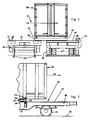
- a container 20 which can be moved transversely to its transport direction, the direction of displacement 21 from a wagon 30 as a transport device to a standing parallel to this truck 40 as a transport device by means of a Verschublys 50, on the upper side of the CCs 22 of the container 20 rest ,
- the wagon 30 stands with its rail wheels 31 'on schematically illustrated rails 23 and is provided with a loading area level 32. In addition, it has front or rear pairs of pins 31.
- Trucks 40 shown schematically as a rear view, which may also be a semitrailer, have wheels 41 'and extensible stand supports 49 common carriers with a loading area plane 42 and pins 41.
- the inventive system consists in the special design of the Verschublys 50, which will be described below, and the modification of wagon and truck as a transport device such that they are equipped with a Vertikalhub réelle whose Vertikalhubteil acts on the CCs and CC on the container or the like, which brings the extraordinary advantage that the containers do not need to be changed, but commercial containers such as standard forwarding interchangeable containers according to UGCISO and overseas containers and swap bodies can be used.
- the modifications of the transport device will be described below.
- Fig. 2 showing a side view of the wagon 30, with one acting on the CC of the container 20 Vertikalhubteil 33 of a total of 34 designated Vertikalhub réelle provided.
- the Verschuble 50 can be so placed next to the front he rear pairs of CCs and then placed in the direction of displacement, which is transverse, preferably perpendicular to the transport direction 24, under the container, ie under the front and under the rear pair CCs become.
- each Verschubm be shorter than the distance of the individual CCS of each pair be dimensioned, it must be ensured only at the transport device (ie the car) and the truck that the loading area level 32, 42 to the area next to the front and the rear Pair CCs extends where the transfer carrier is first deposited before it is placed parallel to the transport direction 24 and transversely to its direction of travel just under the carrier connecting the two CCs of each pair on the bottom of the container.
- the container is designed to be particularly stable and intended to absorb forces in this area.
- the Vertikalhub réelle 34 of the car 30 is in this case as connected to the supply of the transport device Vertikalhubzylinder, preferably designed as a hydraulic or pneumatic cylinder, where it in the Fig. 3 to 6 is shown.
- each one the loading area level 32 forming console plate 37 is provided and serves for placing the Verschubys 50 first of all in the vicinity of the front or rear pair of CCs 22nd
- the Verschublys 50 serves to take place transversely to the transport direction 24 loading and unloading located on the conveyor 30,40 filling device in the form of the container 20, the four so-called CCs on its underside on the loading area level 32,42 of the transport device such as wagon 30th or trucks 40 located front or rear pairs of pins 31 and can be raised by means provided on the transport device 30,40, the container 20 via the CCs 22 lifting Vertikalhubteil 33,43 of Vertikalhub confuses 34,44 are raised, the Verschuby 50 a drive, not shown having.
- the transfer carrier 50 When the container 20 is raised, the transfer carrier 50 can be brought into position in the transport direction 24 between the loading area plane 32, 42 of the transport device 30, 40 and the front and the rear pair of the CCs 22 with respect to the transport direction 24 and, after the vertical lifting part 33, 33 has been lowered attack the cargo area level 32, 42 at the CCs 22.
- the Verschuble 50 is formed for translational transport of the attached container 20 in the direction of displacement 21 transversely to the transport direction 24 by means of the drive.
- the Verschubn 50 has to the Verschub of each pair of pins 31 cross-over (and a non-intervening) starting position in the direction of displacement 21 with seated container 20 at least one opening in its narrow side, downwardly open channel 51 for driving over the pin 31 ( FIG. 4 ).
- the Verschuby 50 at least one downwardly open, adapted to the shape of the pin Recess 52 in its long side on ( FIGS. 3 and 4 ), wherein the recess extends to the channel 51.
- the Verschuby 50 as known per se, to its with a parallel to the transport direction 24 extending shear with raised container 20 successful placement between the loading area level 32,42 of the transport device 30,40 and with respect to the transport direction 24 front or rear pair the CCs 22 two in one side opening, ranging from the top to the bottom, adapted to the shape of the Vertikalhubmaschine 33,43 of Vertikalhubtechniks 34,44, not shown in detail recesses.
- the pins 31 are usually on a foot plate 38 ( FIG. 5 ) arranged.
- a foot plate 38 FIG. 5
- at least one hole 35 (in the region of each pin 31) FIG. 6 ) formed opening, which may also be arranged on the foot plate 32.
- the foot plate 32 is rectangular in plan view and has the pin 31 in the middle.
- the bore 35 is arranged on a diagonal of the rectangular foot plate 38.
- the trained as a piston rod 33 of the hydraulic or pneumatic cylinder Vertikalhub réelle 34,44 can be extended through this bore 35 from below the loading area level. It (33) is designed with its free end to attack on the CC 22, said free end of the piston rod 33 is flat and can be hardened.
- the cylinder 34 is, as in the FIGS. 7 to 9 shown, with respect to the transport device 30,40 is designed to be pivotable.
- the cylinder 34 has two pivot pins 60, which are pivotably mounted in corresponding brackets of a bracket 61 ( FIG. 7 ).
- the cylinder is advantageously with respect to Transporting device formed pivotable, and he can, if it is not needed, pivot in a space-saving and / or non-disturbing transport position.
- the cylinders of the front pair and those dess the rear pair are forcibly guided, for example. Operated by a telescoping rod through the two side members through only one side of the transport and thereby mirror image synchronously pivoted from its transport position to the operating position without the operator to the train has to go around with several cars.
- the cylinder 34 is disposed in the support posts 49 and these stand supports 49 are pivotally mounted, which are pivotally mounted by means of a carrier 64 with respect to the truck 40 fixed pivot bearings 63.
- CCs at other either extra for the container attached points (eg, a CC next to the CC offset plate) or at existing locations such as outside side rails or straps with the free end of the Kobenstange itself or over Attached thereto piston rod attachment to let attack on gripping edges of the container, so that a safe force is introduced into the container.
- the container attached points eg, a CC next to the CC offset plate
- existing locations such as outside side rails or straps with the free end of the Kobenstange itself or over Attached thereto piston rod attachment to let attack on gripping edges of the container, so that a safe force is introduced into the container.
Abstract
Description
Die Erfindung betrifft eine gattungsgemässe Einrichtung nach dem Oberbegriff des Anspruchs 1, nämlich eine Einrichtung zum in Transportrichtung erfolgenden Transport einer mit ihren sogenannten Corner Castings (nachfolgend: CC) in vordere oder hintere Paare von Zapfen der Transporteinrichtung wie Waggon oder Lastkraftwagen eingesetzten Befülleinrichtung, mit einem diese über CCs beim Ausfahren anhebenden und nach dem Ablassen unter die Ladebereichsebene absenkbaren Vertikalhubteil eines Vertikalhubgerätes, wobei das Vertikalhubgerät als Kolbenstange eines an die Versorgung der Transporteinrichtung angeschlossenen Vertikalhubzylinders eines hydraulischen oder pneumatischen Zylinders ausgebildet ist.The invention relates to a generic device according to the preamble of claim 1, namely a means for transporting in the transport direction with its so-called Corner Castings (hereinafter: CC) in front or rear pairs of pins of the transport device such as wagon or truck used filling, with a this vertical lifting part of a vertical lifting device, which raises via CCs during extension and can be lowered below the loading area level after being lowered, wherein the vertical lifting device is designed as a piston rod of a vertical lifting cylinder of a hydraulic or pneumatic cylinder connected to the supply of the transport device.
Es ist eine Einrichtung bekannt (
Container haben bekanntlich an ihrem Boden vier CCs um nur dort zwecks seines Bewegens an dem Container anzugreifen und in der Transportlage zu sichern.Containers are known to attack at their bottom four CCs only there for the purpose of moving it to the container and secure in the transport position.
Von Nachteil bei dieser bekannten Einrichtung ist die Vielzahl der Hydraulik-Verbindungsleitungen zu dem als Betriebshof- und/oder Strassenfahrzeug ausgebildeten und als Transporteinrichtung dienenden Lastkraftwagen, die das Bewegen der Container mit dem Umsetzgerät umständlich macht und dieses an den Lastkraftwagen bindet, was den Betriebsaufwand erhöht und die nutzbare Höhe des Containers erheblich einschränkt. Andererseits wird das Umsetzgerät, das nicht nur die translatorische Bewegung in der Ebene erzeugt, sondern auch die vertikale Hubbewegung beim Aufsatteln des Containers, stark belastet und ist daher störanfällig.A disadvantage of this known device, the variety of hydraulic connection lines to the trained as depot and / or road vehicle and serving as a transport truck, which makes moving the container with the Umsetzgerät cumbersome and this binds to the truck, which increases the operating costs and significantly limits the usable height of the container. On the other hand, the transfer device, which not only generates the translational movement in the plane, but also the vertical lifting movement when mounting the container, heavily loaded and is therefore susceptible to interference.
Es ist ferner eine gattungsgemässe Einrichtung nach dem Oberbegriff des Anspruchs 1 bekannt (
Der Erfindung liegt daher die Aufgabe zugrunde, eine gattungsgemässe Einrichtung vorzuschlagen, die keine Bauartveränderung darstellt und für die deshalb keine Neuzulassung notwendig ist.The invention is therefore based on the object to propose a generic device that does not represent a design change and therefore no new registration is necessary.
Diese Aufgabe wird erfindungsgemäss durch den Gegenstand des Anspruchs 1, also dadurch gelöst, dass im Bereich jedes Zapfens zumindest eine Ausnehmung, z.B. Bohrung für den Durchtritt der mit ihrem freien Ende zum -unmittelbaren oder mittelbaren- Angriff an dem CC ausgebildeten Kolbenstange des Zylinders vorgesehen ist.This object is achieved according to the invention by the subject matter of claim 1, that is, in that in the region of each pin at least one recess, e.g. Bore for the passage of the free-end for -unmittelbaren or indirect attack on the CC formed piston rod of the cylinder is provided.
Durch diese Ausnehmung in unmittelbarer Nähe des Zapfens für die CCs wird also die Kolbenstange des Zylinders hindurch ausgefahren, so dass deren Ende nicht in die Öffnung des CCs, sondern auf dessen Unterseite angreift, und erst danach die Befülleinrichtung angehoben wird. Somit ist es in überraschend einfacher Weise möglich, die Waggons in einfachster Art und Weise umzubauen, ohne die über die CCs die Befülleinrichtung tragenden Zapfen bauartlich irgendwie zu verändern. Infolgedessen bleibt vorteilhafterweise die Betriebs- sowie Bauartgenehmigung des Waggons erhalten.By this recess in the immediate vicinity of the pin for the CCs so the piston rod of the cylinder is extended through, so that their end does not engage in the opening of the CC, but on the underside, and only then the filling is raised. Thus, it is possible in a surprisingly simple manner to rebuild the cars in the simplest manner, without changing the style about the CCs the filling bearing pin. As a result, advantageously the operation and type approval of the wagon is maintained.
Die Erfindung als System teilt also die Funktionen des Angreifens an der Befülleinrichtung sowie des vertikalen Anhebens einerseits der Transporteinrichtung wie Waggon, Lastkraftwagen oder auch Sattelanhänger zu, wohingegen andererseits die mit dieser Transporteinrichtung zusammenwirkende, als Verschubträger ausgebildete erfindungsgemässe Einrichtung mit einen eigenen Antrieb zum translatorischen Bewegen des auf ihm aufliegenden Containers als Befülleinrichtung ausgestattet ist. Es kommt bei dem erfindungsgemässen System hinzu, dass herkömmliche Container weiter verwendet werden können, vorausgesetzt, sie verfügen über CCs. An der Transporteinrichtung, die im übrigen überdies auch zugleich weiter in herkömmlichen Containerterminals eingesetzt werden kann, müssen nur geringfügige Anbauten vorgesehen werden, nämlich Vertikalhubgeräte mit einem ausfahrbaren Vertikalhubteil, das den Container über die Unteseite von dessen CCs anhebt und das beim Absenken bis vorzugsweise vollständig unter die Ladebereichsebene eingefahren werden kann, damit es beim Transport in quer zu der Transportrichtung verlaufenden Verschieberichtung nicht störend im Wege ist. Vor dem Absenken muss aber je ein Verschubträger unter den Container, also unter dessen vorderes und unter dessen hinteres Paar CCs und über der Ladebereichsebene der Transporteinrichtung in Stellung gebracht werden. Hierzu kann jeder Verschubträger kürzer als der Abstand der einzelnen CCs jedes Paars ausgestaltet sein; es muss lediglich an der Transporteinrichtung sichergestellt sein, dass sich die Ladebereichsebene bis in den Bereich neben dem vorderen sowie dem hinteren Paar CCs erstreckt, wo der Verschubträger zunächst abgesetzt wird, bevor er in Transportrichtung und quer zu seiner Verschieberichtung genau unter den -zwei CCs auf der Unterseite des Containers verbindenden- Träger plaziert wird. Diese Zusätze an der Transporteinrichtung sind geringfügig sowie einfach und unproblematisch sowie ohne Verlust der Betriebs- sowie Bauartgenehmigung des Waggons anzubringen.The invention as a system thus assigns the functions of attacking the filling device and the vertical lifting on the one hand the transport device such as wagon, truck or semitrailer, whereas on the other hand cooperating with this transport device, designed as a shift support inventive device with its own drive for translational movement of the on it resting containers is equipped as a filling device. It is added in the inventive system that conventional containers can be used, assuming they have CCs. On the transport device, which moreover can also be used at the same time in conventional container terminals, only minor attachments must be provided, namely Vertikalhubgeräte with an extendable Vertikalhubteil that lifts the container on the underside of the CCs and when lowering to preferably completely below the loading area level can be retracted so that it is not disturbing in the transport in transverse to the direction of transport displacement direction. Before lowering but ever a Verschubträger under the container, so under its front and under the rear pair CCs and over the loading area level of the transport device must be brought into position. For this purpose, each shift carrier can be configured shorter than the distance of the individual CCs of each pair; it must be ensured only on the transport device that the loading area level extends into the area adjacent to the front and the rear pair CCs, where the Verschubträger is first discontinued before it in the transport direction and across its direction exactly below the -zwei CCs on placed on the underside of the container connecting carrier. These additions to the transport device are minor and easy and without problems and without loss of operating and type approval of the wagon to install.
Insgesamt ergibt sich erfindungsgemäss, dass sich die auch nachrüstbaren Einbauten im Gewichtslimit für Zulassungsänderungen bewegen. Schon existierende Umschlagstechniken auf der Transporteinrichtung z.B. dem Waggon können weiter genutzt werden. Andererseits können mit dem erfindungsgemässen System versehene Transporteinrichtungen ohne Einschränkung für den bislang üblichen Einsatz nach dem Stand der Technik weiter genutzt werden. Weiter können jegliche über CCs verfügenende Container ohne Änderungen eingesetzt werden und der Verschubträger nicht für einen Hub, sondern lediglich für eine translatorische Bewegung in der Ebene ausgelegt sein, was nicht nur das Handling, sondern auch Aufbau verbessert und die Störanfälligkeit verringert.Overall, according to the invention results that the retrofit internals move in the weight limit for registration changes. Existing handling techniques on the transport equipment such as the wagon can still be used. On the other hand, provided with the inventive system transport devices without limitation for the so far usual use according to the prior art continue to be used. Furthermore, any container having CCs can be used without changes and the displacing support can not be designed for a lift, but only for a translational movement in the plane, which not only improves the handling, but also construction and reduces the susceptibility to interference.
Zweckmässigerweise ist das freie Ende der Kolbenstange des Zylinders eben ausgebildet sowie gehärtet, um im harten täglichen Betrieb eine hohe Standzeit aufzuweisen.Conveniently, the free end of the piston rod of the cylinder is flat and hardened to have a high durability in hard daily operation.
Besonders einfach gestaltet sich der Umbau, wenn die Zapfen an einer Fussplatte angeordnet sind und diese die Bohrung aufweist, wobei es aus Platzgründen vorteilhaft ist, wenn die Fussplatte in Draufsicht rechteckförmig ausgebildet ist und den Zapfen mittig aufweist und die Bohrung auf einer Diagonalen der Fussplatte, also in deren Eckbereich angeordnet ist.The conversion is particularly simple when the pins are arranged on a foot plate and this has the bore, wherein it is advantageous for reasons of space, if the foot plate is rectangular in plan view and has the pin centered and the bore on a diagonal of the foot plate, So is arranged in the corner area.
Nachdem der Zylinder eine von dem benötigten Hub zwingend vorgegebene Bauhöhe erfordert, kann er nicht in Bereichen vorgesehen werden, in denen der Längsträger schon eine geringere Bauhöhe aufweist und/oder die Drehschemel oder die schwenkbaren Radachsen vorgesehen sind, und ist der Zylinder daher vorteilhafterweise bezüglich der Transportein- richtung schwenkbar ausgebildet ist, und er lässt sich, wenn er nicht benötigt wird, in eine raumsparende und/oder nicht störende Transportlage schwenken. Zweckmässigerweise werden die Zylinder des vordere Paars und auch jene dess hinteren Paars zwangsgeführt, bspw. von einer telekopierbaren Stange durch die beiden Längsträger hindurch von nur einer Seite der Transporteinrichtung betätigt und dabei spiegelbildlich synchron aus ihrer Transportlage in die Betriebslage geschwenkt, ohne dass die Bedienungsperson um den Zug mit mehreren Waggons herumgehen muss.After the cylinder requires a predetermined by the required stroke height, it can not be provided in areas where the longitudinal beam already has a lower height and / or the fifth wheel or the pivoting axles are provided, and the cylinder is therefore advantageously with respect Transporting device is designed to be pivotable, and it can, if it is not needed, pivot in a space-saving and / or non-disturbing transport position. Expediently, the cylinders of the front pair and also those of the rear pair are forcibly guided, for example actuated by a telescoping rod through the two side members, from only one side of the transport device and thereby in mirror image synchronism from their transport position into the conveyor belt Operational position pivoted, without the operator has to go around the train with several cars.
Bei als Lastkraftwagen ausgebildeter Transporteinrichtung sind über dessen Breite hervorstehende Standstützen vorgesehen, in denen auch die Zylinder angeordnet sein können und die erfindungsgemäss innerhalb des Lichtraumprofils des Lastkraftwagen einschwenkbar ausgebildet sind, so dass dieser beim Rückwärtsfahren den auf Füssen stehenden Container von vorne unterfahren kann. Die Standstützen kippen zugleich eine Konsole in den von dem Lastkraftwagen und Waggon gebildeten Zwischenraum, so dass der Verschubträger in diesem Bereich besser und über eine grössere Länge geführt ist.When trained as a truck transport device over its width projecting stand supports are provided, in which the cylinder can be arranged and which according to the invention can be pivoted within the clearance gauge of the truck so that it can move under the standing on feet container from the front when reversing. The pedestals tilt at the same time a console in the intermediate space formed by the truck and wagon, so that the Verschubträger is performed better and over a greater length in this area.
Die gattungsgemäss bekannte Einrichtung zum quer zur Transportrichtung erfolgenden Auf- und Abladen von auf einer Transporteinrichtung befindlichen Befülleinrichtung, die über vier CCs an ihrer Unterseite auf an der Ladebereichsebene der Transporteinrichtung wie Waggon oder Lastkraftwagen befindlichen vorderen oder hinteren Paaren von Zapfen aufsetzbar und mittels an der Transporteinrichtung vorgesehenen, den Container über die CCs anhebenden Vertikalhubteil eines Vertikalhubgerätes anhebbar sind, wobei die Einrichtung einen Antrieb aufweist und als bei angehobener Befülleinrichtung in Transportrichtung zwischen der Ladebereichsebene der Transporteinrichtung und das bezüglich der Transportrichtung vordere und das hintere Paar der CCs parallel zu der Transportrichtung und nach Absenken des Vertikalhubteiles unter die Ladebereichsebene bringbar, nach dem Absenken an den CCs angreifend und zum translatorischen Transport der aufgesetzten Befülleinrichtung in Verschieberichtung quer zu der Transportrichtung mittels des Antriebes ausgebildet sowie die Einrichtung als Verschubträger ausgebildet ist, weist dieser erfindungsgemäss zwecks dessen Verschub von einer entweder jedes Paar Zapfen übergreifenden oder dazwischen befindlichen Ausgangslage in Verschieberichtung mit aufsitzender Befülleinrichtung zumindest einen in seiner Schmalseite mündenden, nach unten offenen Kanal zum Überfahren des zumindest einen Zapfens des Paars aufweist.The generic known device for transversely to the transport direction loading and unloading located on a conveyor filling, the four CCs on its underside placed on the loading area level of the transport device such as wagon or truck front or rear pairs of pins and means on the transport device provided, the container via the CCs lifting vertical lifting a Vertikalhubgerätes are raised, wherein the device has a drive and with the filling device in the transport direction between the loading area level of the transport device and the front with respect to the transport direction and the rear pair of CCs parallel to the transport direction and after Lowering the Vertikalhubteiles below the loading area level brought, after lowering the CCs attacking and translational transport of the attached filling device in the direction transverse formed to the transport direction by means of the drive and the device is designed as a Verschubträger, this has according to the invention for the purpose of its Verschub from either either pair of spigot cross-over or starting position in the displacement direction with seated filling at least one opening in its narrow side, downwardly open channel for overriding the at least one pin of the pair ,
Wenn jeder Verschubträger länger als der Abstand der einzelnen CCs jedes Paars sein soll, so weist in vorteilhafter Weiterbildung der Erfindung der Verschubträger zwecks dessen mit einem parallel zu der Transportrichtung verlaufenden Querschub erfolgenden Plazierung zwischen die Ladebereichsebene der Transporteinrichtung und das bezüglich der Transportrichtung vordere oder hintere Paar der CCs bei angehobenem Container nicht nur, wie an sich bekannt, zwei in dessen einer Seite mündende, von der Ober- bis zur Unterseite reichende, an die Form der Vertikalhubteile des Vertikalhubgeräts angepasste Ausnehmungen, sondern zumindest eine nach unten offene Ausnehmungen in der Langseite auf, um die Zapfen überfahren zu können, wobei zweckmässigerweise die Ausnehmungen in der Langseite bis zu dem Kanal reicht.If each Verschubträger should be longer than the distance of the individual CCs each pair, so points in an advantageous embodiment of the invention, the Verschubträger in order to its taking place with a parallel to the transport direction transverse thrust placement between the loading area level of the transport device and with respect to the transport direction front or rear pair the CCs with raised container not only, as is well known, two in one side opening, ranging from the top to the bottom, adapted to the shape of the Vertikalhubteile the Vertikalhubgeräts recesses, but at least one downwardly open recesses in the long side in order to be able to drive over the pins, wherein expediently the recesses in the long side extends to the channel.
Um während des translatorischen Transports der aufgesetzten Befülleinrichtung in Verschieberichtung diese zu sichern, kann sie auf ihrer Oberseite in vorteilhafter Ausgestaltung selbst Verschubträgerzapfen aufweisen.In order to secure them during the translational transport of the attached filling device in the displacement direction, it may itself have on its upper side in an advantageous embodiment Verschubträgerzapfen.
Weitere zweckmässige Ausgestaltungen und Weiterbildungen der Erfindung sind in den Unteransprüchen gekennzeichnet.Further expedient refinements and developments of the invention are characterized in the subclaims.
Auführungsbeispiele der Erfindung werden nachfolgend unter Bezugnahme auf die Zeichnung näher erläutert. In dieser zeigt:
-
Fig. 1 ein erfindungsgemässes System zum Auf- und Abladen von Containern; -
Fig. 2 eine Seitenansicht einer als Waggon ausgebildete Transporteinrichtung; -
Fig. 3 das System gemässFig. 1 in teilweise abgebrochener Darstellung und grösserem Massstab mit einer als Waggon ausgebildeten Transporteinrichtung, in einem schon etwas angehobenen ersten Betriebszustand; -
Fig. 4 das System gemässFig. 3 in einem zweiten Betriebszustand; -
Fig. 5 das System gemässFig. 3 in einem dritten Betriebszustand; -
Fig. 6 das System gemässFig. 5 , in teilweise abgebrochener Draufsicht. -
Fig. 7 das System gemässFig. 5 , in erster Weiterbildung; -
Fig. 8 das System gemässFig. 5 , in zweiter Weiterbildung für einen Lastkraftwagen im Betriebszustand und -
Fig. 9 das System gemässFig. 8 , im Transportzustand.
-
Fig. 1 a system according to the invention for loading and unloading containers; -
Fig. 2 a side view of a trained as a wagon transport device; -
Fig. 3 the system according toFig. 1 in a partially broken representation and larger scale with a trained as a wagon transport device, in a slightly raised first operating condition; -
Fig. 4 the system according toFig. 3 in a second operating state; -
Fig. 5 the system according toFig. 3 in a third operating condition; -
Fig. 6 the system according toFig. 5 , in a partially broken plan view. -
Fig. 7 the system according toFig. 5 in first education; -
Fig. 8 the system according toFig. 5 , in a second development for a truck in the operating state and -
Fig. 9 the system according toFig. 8 , in transport condition.
Zur Straffung der Zeichnungsbeschreibung sollen mit gleichem Bezugszeichen versehene Teile auch identisch sein, so dass nicht jedes Teil jeder einzelnen Figur beschrieben werden muss.To streamline the description of the drawing, parts provided with the same reference number should also be identical, so that not every part of each individual figure must be described.
In
Der Waggon 30 steht mit seinen Schienenrädern 31' auf schematisch dargestellten Schienen 23 und ist mit einer Ladebereichsebene 32 versehen. Ausserdem weist er vordere oder hintere Paare von Zapfen 31 auf.The
Der in
Das erfindungsgemässe System besteht in der speziellen Ausgestaltung des Verschubträgers 50, die nachfolgend noch beschrieben werden wird, sowie der Modifikation von Waggon und Lastkraftwagen als Transporteinrichtung dergestalt, dass diese mit einem Vertikalhubgerät ausgestattet werden, dessen Vertikalhubteil an den CCs angreift und über das CC den Container oder dergleichen anheben kann, was den ausserordentlichen Vorteil mit sich bringt, dass die Container nicht geändert werden müssen, sondern handelsübliche Container wie Standard-Spedition-Wechselbehälter nach UGCISO sowie Übersee-Container sowie Wechselbrücken Einsatz finden können. Die Modifikationen der Transporteinrichtung werden nachfolgend beschrieben.The inventive system consists in the special design of the
So ist in
Das Vertikalhubgerät 34 des Waggons 30 ist hierbei als an die Versorgung der Transporteinrichtung angeschlossener Vertikalhubzylinder, vorzugsweise als hydraulischer oder pneumatischer Zylinder ausgebildet, wo es in den
Zur Erzielung einer biegesteifen Ladebereichsebene 32 ist die Transporteinrichtung, zum Beispiel der Waggon 30, auf dessen beiden zueinander parallelen Längsträgern 36 sowie zwischen den hinteren sowie dem vorderen Paar der an dem hinteren beziehungsweise dem vorderen Paar der CCs 22 an der Unterseite des Containers 20 angreifenden Vertikalhubteile 33 der Vertikalhubgeräte 34, wie in
Der Verschubträgers 50 dient dabei zum quer zur Transportrichtung 24 erfolgenden Auf- und Abladen von auf der Transporteinrichtung 30,40 befindlichen Befülleinrichtung in Form des Containers 20, der über vier sogenannte CCs an ihrer Unterseite auf an der Ladebereichsebene 32,42 der Transporteinrichtung wie Waggon 30 oder Lastkraftwagen 40 befindlichen vorderen oder hinteren Paare von Zapfen 31 aufsetzbar und mittels an der Transporteinrichtung 30,40 vorgesehenen, den Container 20 über die CCs 22 anhebenden Vertikalhubteil 33,43 des Vertikalhubgerätes 34,44 anhebbar sind, wobei der Verschubträger 50 einen nicht gezeigten Antrieb aufweist. Bei angehobenem Container 20 kann der Verschubträger 50 in Transportrichtung 24 zwischen die Ladebereichsebene 32,42 der Transporteinrichtung 30,40 und das bezüglich der Transportrichtung 24 vordere und das hintere Paar der CCs 22 in Stellung gebracht werden und nach dem Absenken des Vertikalhubteiles 33,43 unter die Ladebereichsebene 32,42 an den CCs 22 angreifen. Zugleich ist der Verschubträger 50 zum translatorischen Transport des aufgesetzten Containers 20 in Verschieberichtung 21 quer zu der Transportrichtung 24 mittels des Antriebes ausgebildet.The
Der Verschubträger 50 weist zu dessen Verschub von einer jedes Paar Zapfen 31 übergreifenden (und einer nicht dazwischen befindlichen) Ausgangslage in Verschieberichtung 21 mit aufsitzendem Container 20 zumindest einen in seiner Schmalseite mündenden, nach unten offenen Kanal 51 zum Überfahren der Zapfen 31 auf (
Um bei angehobenem Container 20 den Verschubträger 50 in Transportrichtung 24 mit einem Querschub unter das vordere und das hintere Paar der CCs 22 trotz der Zapfen 31 in Stellung bringen zu können, weist der Verschubträger 50 zumindest eine nach unten offene, an die Form der Zapfen angepasste Aussparung 52 in seiner Langseite auf (
Im übrigen weist der Verschubträger 50, wie an sich bekannt, zu dessen mit einem parallel zu der Transportrichtung 24 verlaufenden Querschub bei angehobenem Container 20 erfolgenden Plazierung zwischen die Ladebereichsebene 32,42 der Transporteinrichtung 30,40 und das bezüglich der Transportrichtung 24 vordere oder hintere Paar der CCs 22 zwei in dessen einer Seite mündende, von der Ober- bis zur Unterseite reichende, an die Form der Vertikalhubteile 33,43 des Vertikalhubgerätes 34,44 angepasste, nicht näher gezeigte Ausnehmungen auf.Incidentally, the
Die Zapfen 31 sind üblicherweise an einer Fussplatte 38 (
Das als Kolbenstange 33 des hydraulischen oder pneumatischen Zylinders ausgebildeten Vertikalhubgerät 34,44 kann durch diese Bohrung 35 von unterhalb der Ladebereichsebene hindurch ausgefahren werden. Sie (33) ist dabei mit ihrem freien Ende zum Angriff an dem CC 22 ausgebildet, wobei dieses freie Ende der Kolbenstange 33 eben ausgebildet ist sowie gehärtet sein kann.The trained as a
Der Zylinder 34 ist, wie in den
Bei dem Lastkraftwagen 40 ist der Zylinder 34 in den Standstützen 49 angeordnet und sind diese Standstützen 49 schwenkbar ausgebildet, die mittels eines Trägers 64 an bezüglich des Lastkraftwagens 40 fest angeordneten Schwenlager 63 schwenkbar gelagert sind.In the
Erfindungsgemäss ist auch möglich, anstelle an den CCs an anderen entweder dafür extra an dem Container angebrachten Stellen (z.B. eine neben dem CC nach innen versetzten Platte) oder an schon vorhandenen Stellen wie aussenseitigen Längsträgern oder Gurten mit dem freien Ende der Kobenstange selbst oder aber über daran befestigten Kolbenstangenaufsatz, auch an Greifkanten des Containers angreifen zu lassen, so dass eine sichere Krafteinleitung in den Container erfolgt.According to the invention is also possible, instead of the CCs at other either extra for the container attached points (eg, a CC next to the CC offset plate) or at existing locations such as outside side rails or straps with the free end of the Kobenstange itself or over Attached thereto piston rod attachment to let attack on gripping edges of the container, so that a safe force is introduced into the container.
Claims (15)
Priority Applications (5)
| Application Number | Priority Date | Filing Date | Title |
|---|---|---|---|
| AT08006973T ATE473188T1 (en) | 2008-04-08 | 2008-04-08 | DEVICE FOR TRANSPORTING A FILLING DEVICE |
| PL08006973T PL2108605T3 (en) | 2008-04-08 | 2008-04-08 | Device for transporting a container |
| DK08006973.5T DK2108605T3 (en) | 2008-04-08 | 2008-04-08 | Device for transporting a filling device |
| DE502008000903T DE502008000903D1 (en) | 2008-04-08 | 2008-04-08 | Device for transporting a filling device |
| EP08006973A EP2108605B1 (en) | 2008-04-08 | 2008-04-08 | Device for transporting a container |
Applications Claiming Priority (1)
| Application Number | Priority Date | Filing Date | Title |
|---|---|---|---|
| EP08006973A EP2108605B1 (en) | 2008-04-08 | 2008-04-08 | Device for transporting a container |
Publications (2)
| Publication Number | Publication Date |
|---|---|
| EP2108605A1 true EP2108605A1 (en) | 2009-10-14 |
| EP2108605B1 EP2108605B1 (en) | 2010-07-07 |
Family
ID=39744748
Family Applications (1)
| Application Number | Title | Priority Date | Filing Date |
|---|---|---|---|
| EP08006973A Not-in-force EP2108605B1 (en) | 2008-04-08 | 2008-04-08 | Device for transporting a container |
Country Status (5)
| Country | Link |
|---|---|
| EP (1) | EP2108605B1 (en) |
| AT (1) | ATE473188T1 (en) |
| DE (1) | DE502008000903D1 (en) |
| DK (1) | DK2108605T3 (en) |
| PL (1) | PL2108605T3 (en) |
Cited By (4)
| Publication number | Priority date | Publication date | Assignee | Title |
|---|---|---|---|---|
| WO2014203024A1 (en) | 2013-06-17 | 2014-12-24 | Safe Green Logistic A/S | Container transfer system and method of its operation |
| CN105084220A (en) * | 2015-08-04 | 2015-11-25 | 浙江双友物流器械股份有限公司 | Double-container synchronous loading and unloading system for containers |
| WO2018029378A1 (en) | 2016-08-11 | 2018-02-15 | Safe Green Logistics A/S | A transportation unit suitable for transporting cargo |
| WO2023031486A1 (en) | 2021-09-06 | 2023-03-09 | Safe Green Logistics A/S | A transport vehicle |
Citations (4)
| Publication number | Priority date | Publication date | Assignee | Title |
|---|---|---|---|---|
| DE19501543C1 (en) | 1995-01-19 | 1996-08-08 | Wolfgang Bermueller | Transfer device for interchangeable containers |
| EP0831002A1 (en) | 1996-09-24 | 1998-03-25 | MANNESMANN Aktiengesellschaft | Apparatus for horizontal transfer of loads |
| WO2007051631A1 (en) * | 2005-11-04 | 2007-05-10 | Unseld Hans G | Mobile handling unit |
| EP1840056A1 (en) | 2006-03-26 | 2007-10-03 | Wolfgang Bermüller | Device for loading and unloading a filler device transversely to the direction of transport |
-
2008
- 2008-04-08 PL PL08006973T patent/PL2108605T3/en unknown
- 2008-04-08 DE DE502008000903T patent/DE502008000903D1/en active Active
- 2008-04-08 AT AT08006973T patent/ATE473188T1/en active
- 2008-04-08 DK DK08006973.5T patent/DK2108605T3/en active
- 2008-04-08 EP EP08006973A patent/EP2108605B1/en not_active Not-in-force
Patent Citations (4)
| Publication number | Priority date | Publication date | Assignee | Title |
|---|---|---|---|---|
| DE19501543C1 (en) | 1995-01-19 | 1996-08-08 | Wolfgang Bermueller | Transfer device for interchangeable containers |
| EP0831002A1 (en) | 1996-09-24 | 1998-03-25 | MANNESMANN Aktiengesellschaft | Apparatus for horizontal transfer of loads |
| WO2007051631A1 (en) * | 2005-11-04 | 2007-05-10 | Unseld Hans G | Mobile handling unit |
| EP1840056A1 (en) | 2006-03-26 | 2007-10-03 | Wolfgang Bermüller | Device for loading and unloading a filler device transversely to the direction of transport |
Cited By (4)
| Publication number | Priority date | Publication date | Assignee | Title |
|---|---|---|---|---|
| WO2014203024A1 (en) | 2013-06-17 | 2014-12-24 | Safe Green Logistic A/S | Container transfer system and method of its operation |
| CN105084220A (en) * | 2015-08-04 | 2015-11-25 | 浙江双友物流器械股份有限公司 | Double-container synchronous loading and unloading system for containers |
| WO2018029378A1 (en) | 2016-08-11 | 2018-02-15 | Safe Green Logistics A/S | A transportation unit suitable for transporting cargo |
| WO2023031486A1 (en) | 2021-09-06 | 2023-03-09 | Safe Green Logistics A/S | A transport vehicle |
Also Published As
| Publication number | Publication date |
|---|---|
| ATE473188T1 (en) | 2010-07-15 |
| EP2108605B1 (en) | 2010-07-07 |
| DE502008000903D1 (en) | 2010-08-19 |
| PL2108605T3 (en) | 2011-01-31 |
| DK2108605T3 (en) | 2010-08-09 |
Similar Documents
| Publication | Publication Date | Title |
|---|---|---|
| EP3268257B1 (en) | Raisable carrying device | |
| DE102009012159A1 (en) | Goods enveloping device for enveloping e.g. containers, from road to rail and vice versa, has lateral transport unit designed as shuttle carriage that is roll-guided on transport rollers in lateral direction | |
| EP0733003B1 (en) | Vehicle with superstructure | |
| EP1840056B1 (en) | Device for loading and unloading a filler device transversely to the direction of transport | |
| EP2108605B1 (en) | Device for transporting a container | |
| EP0645293B1 (en) | Freight wagon for forming a railway wagon combination for combined rail and road transport | |
| DE19823380A1 (en) | Device for reducing the axle load of a multi-axle mobile telescopic crane | |
| EP0045398B1 (en) | Combined changing and tipping device for utility-vehicle bodies | |
| EP0064053A1 (en) | Wagon with lowered platform for the railway transport of motor vehicles and giant containers | |
| DE202008008711U1 (en) | Rail loading wagons | |
| EP3299244B1 (en) | Track-bound freight wagon for transporting stand-alone transport vehicles | |
| CH691314A5 (en) | Track-laying machine. | |
| EP3296175B1 (en) | Method for transporting a semitrailer | |
| EP3909808B1 (en) | Vehicle loading system for a vehicle cabin | |
| EP3461785B1 (en) | Crane | |
| DE1912830B2 (en) | Trucks for the transport of swap bodies provided with supports | |
| DE8011608U1 (en) | VEHICLE FOR TRANSPORTING PASSENGER CARS | |
| DE202016008550U1 (en) | Railway wagon with a semitrailer dropped on it | |
| DE2753962A1 (en) | ADDITIONAL DEVICE FOR HANDLING TRANSPORT CONTAINERS | |
| DE1215740B (en) | Transport trolleys, in particular transport rail vehicles, with two loading areas one above the other | |
| DE202022000516U1 (en) | Interchangeable platform for railway wagons, railway wagon, and system with a railway wagon and an interchangeable platform | |
| CH693334A5 (en) | Mechanical handling system, especially for containers for road and rail transport | |
| EP3604072A1 (en) | Liftable carrying device | |
| DE102012105636A1 (en) | Lifting mechanism arranged on loading platform of railway container support carriage, has piston force confinement device to limit the piston force applied by lifting plate on bottom side of interchangeable structure | |
| DE2945438A1 (en) | Container lorry with articulated conversion - has swivel coupling with height control |
Legal Events
| Date | Code | Title | Description |
|---|---|---|---|
| PUAI | Public reference made under article 153(3) epc to a published international application that has entered the european phase |
Free format text: ORIGINAL CODE: 0009012 |
|
| 17P | Request for examination filed |
Effective date: 20090526 |
|
| AK | Designated contracting states |
Kind code of ref document: A1 Designated state(s): AT BE BG CH CY CZ DE DK EE ES FI FR GB GR HR HU IE IS IT LI LT LU LV MC MT NL NO PL PT RO SE SI SK TR |
|
| AX | Request for extension of the european patent |
Extension state: AL BA MK RS |
|
| GRAP | Despatch of communication of intention to grant a patent |
Free format text: ORIGINAL CODE: EPIDOSNIGR1 |
|
| GRAS | Grant fee paid |
Free format text: ORIGINAL CODE: EPIDOSNIGR3 |
|
| GRAA | (expected) grant |
Free format text: ORIGINAL CODE: 0009210 |
|
| AKX | Designation fees paid |
Designated state(s): AT BE BG CH CY CZ DE DK EE ES FI FR GB GR HR HU IE IS IT LI LT LU LV MC MT NL NO PL PT RO SE SI SK TR |
|
| AK | Designated contracting states |
Kind code of ref document: B1 Designated state(s): AT BE BG CH CY CZ DE DK EE ES FI FR GB GR HR HU IE IS IT LI LT LU LV MC MT NL NO PL PT RO SE SI SK TR |
|
| REG | Reference to a national code |
Ref country code: GB Ref legal event code: FG4D Free format text: NOT ENGLISH |
|
| REG | Reference to a national code |
Ref country code: CH Ref legal event code: EP Ref country code: CH Ref legal event code: NV Representative=s name: SAEGER & PARTNER PATENT- UND RECHTSANWAELTE |
|
| REG | Reference to a national code |
Ref country code: SE Ref legal event code: TRGR |
|
| REG | Reference to a national code |
Ref country code: NL Ref legal event code: T3 |
|
| REG | Reference to a national code |
Ref country code: DK Ref legal event code: T3 |
|
| REG | Reference to a national code |
Ref country code: IE Ref legal event code: FG4D |
|
| REF | Corresponds to: |
Ref document number: 502008000903 Country of ref document: DE Date of ref document: 20100819 Kind code of ref document: P |
|
| PG25 | Lapsed in a contracting state [announced via postgrant information from national office to epo] |
Ref country code: SI Free format text: LAPSE BECAUSE OF FAILURE TO SUBMIT A TRANSLATION OF THE DESCRIPTION OR TO PAY THE FEE WITHIN THE PRESCRIBED TIME-LIMIT Effective date: 20100707 |
|
| REG | Reference to a national code |
Ref country code: NO Ref legal event code: T2 Effective date: 20100707 |
|
| LTIE | Lt: invalidation of european patent or patent extension |
Effective date: 20100707 |
|
| PG25 | Lapsed in a contracting state [announced via postgrant information from national office to epo] |
Ref country code: LT Free format text: LAPSE BECAUSE OF FAILURE TO SUBMIT A TRANSLATION OF THE DESCRIPTION OR TO PAY THE FEE WITHIN THE PRESCRIBED TIME-LIMIT Effective date: 20100707 Ref country code: FI Free format text: LAPSE BECAUSE OF FAILURE TO SUBMIT A TRANSLATION OF THE DESCRIPTION OR TO PAY THE FEE WITHIN THE PRESCRIBED TIME-LIMIT Effective date: 20100707 |
|
| REG | Reference to a national code |
Ref country code: PL Ref legal event code: T3 |
|
| REG | Reference to a national code |
Ref country code: IE Ref legal event code: FD4D |
|
| PG25 | Lapsed in a contracting state [announced via postgrant information from national office to epo] |
Ref country code: HR Free format text: LAPSE BECAUSE OF FAILURE TO SUBMIT A TRANSLATION OF THE DESCRIPTION OR TO PAY THE FEE WITHIN THE PRESCRIBED TIME-LIMIT Effective date: 20100707 Ref country code: CY Free format text: LAPSE BECAUSE OF FAILURE TO SUBMIT A TRANSLATION OF THE DESCRIPTION OR TO PAY THE FEE WITHIN THE PRESCRIBED TIME-LIMIT Effective date: 20100707 Ref country code: IS Free format text: LAPSE BECAUSE OF FAILURE TO SUBMIT A TRANSLATION OF THE DESCRIPTION OR TO PAY THE FEE WITHIN THE PRESCRIBED TIME-LIMIT Effective date: 20101107 Ref country code: BG Free format text: LAPSE BECAUSE OF FAILURE TO SUBMIT A TRANSLATION OF THE DESCRIPTION OR TO PAY THE FEE WITHIN THE PRESCRIBED TIME-LIMIT Effective date: 20101007 |
|
| PG25 | Lapsed in a contracting state [announced via postgrant information from national office to epo] |
Ref country code: GR Free format text: LAPSE BECAUSE OF FAILURE TO SUBMIT A TRANSLATION OF THE DESCRIPTION OR TO PAY THE FEE WITHIN THE PRESCRIBED TIME-LIMIT Effective date: 20101008 Ref country code: LV Free format text: LAPSE BECAUSE OF FAILURE TO SUBMIT A TRANSLATION OF THE DESCRIPTION OR TO PAY THE FEE WITHIN THE PRESCRIBED TIME-LIMIT Effective date: 20100707 |
|
| PG25 | Lapsed in a contracting state [announced via postgrant information from national office to epo] |
Ref country code: IE Free format text: LAPSE BECAUSE OF FAILURE TO SUBMIT A TRANSLATION OF THE DESCRIPTION OR TO PAY THE FEE WITHIN THE PRESCRIBED TIME-LIMIT Effective date: 20100707 |
|
| PLBE | No opposition filed within time limit |
Free format text: ORIGINAL CODE: 0009261 |
|
| STAA | Information on the status of an ep patent application or granted ep patent |
Free format text: STATUS: NO OPPOSITION FILED WITHIN TIME LIMIT |
|
| PG25 | Lapsed in a contracting state [announced via postgrant information from national office to epo] |
Ref country code: CZ Free format text: LAPSE BECAUSE OF FAILURE TO SUBMIT A TRANSLATION OF THE DESCRIPTION OR TO PAY THE FEE WITHIN THE PRESCRIBED TIME-LIMIT Effective date: 20100707 Ref country code: RO Free format text: LAPSE BECAUSE OF FAILURE TO SUBMIT A TRANSLATION OF THE DESCRIPTION OR TO PAY THE FEE WITHIN THE PRESCRIBED TIME-LIMIT Effective date: 20100707 Ref country code: EE Free format text: LAPSE BECAUSE OF FAILURE TO SUBMIT A TRANSLATION OF THE DESCRIPTION OR TO PAY THE FEE WITHIN THE PRESCRIBED TIME-LIMIT Effective date: 20100707 Ref country code: SK Free format text: LAPSE BECAUSE OF FAILURE TO SUBMIT A TRANSLATION OF THE DESCRIPTION OR TO PAY THE FEE WITHIN THE PRESCRIBED TIME-LIMIT Effective date: 20100707 |
|
| 26N | No opposition filed |
Effective date: 20110408 |
|
| PG25 | Lapsed in a contracting state [announced via postgrant information from national office to epo] |
Ref country code: ES Free format text: LAPSE BECAUSE OF FAILURE TO SUBMIT A TRANSLATION OF THE DESCRIPTION OR TO PAY THE FEE WITHIN THE PRESCRIBED TIME-LIMIT Effective date: 20101018 |
|
| REG | Reference to a national code |
Ref country code: DE Ref legal event code: R097 Ref document number: 502008000903 Country of ref document: DE Effective date: 20110408 |
|
| BERE | Be: lapsed |
Owner name: BERMULLER, WOLFGANG Effective date: 20110430 |
|
| PG25 | Lapsed in a contracting state [announced via postgrant information from national office to epo] |
Ref country code: MC Free format text: LAPSE BECAUSE OF NON-PAYMENT OF DUE FEES Effective date: 20110430 |
|
| PG25 | Lapsed in a contracting state [announced via postgrant information from national office to epo] |
Ref country code: MT Free format text: LAPSE BECAUSE OF FAILURE TO SUBMIT A TRANSLATION OF THE DESCRIPTION OR TO PAY THE FEE WITHIN THE PRESCRIBED TIME-LIMIT Effective date: 20100707 |
|
| PG25 | Lapsed in a contracting state [announced via postgrant information from national office to epo] |
Ref country code: NO Free format text: LAPSE BECAUSE OF NON-PAYMENT OF DUE FEES Effective date: 20110430 Ref country code: BE Free format text: LAPSE BECAUSE OF NON-PAYMENT OF DUE FEES Effective date: 20110430 |
|
| REG | Reference to a national code |
Ref country code: DK Ref legal event code: EBP |
|
| PG25 | Lapsed in a contracting state [announced via postgrant information from national office to epo] |
Ref country code: DK Free format text: LAPSE BECAUSE OF NON-PAYMENT OF DUE FEES Effective date: 20110430 |
|
| PGFP | Annual fee paid to national office [announced via postgrant information from national office to epo] |
Ref country code: NL Payment date: 20120501 Year of fee payment: 5 |
|
| PGFP | Annual fee paid to national office [announced via postgrant information from national office to epo] |
Ref country code: GB Payment date: 20120423 Year of fee payment: 5 Ref country code: SE Payment date: 20120426 Year of fee payment: 5 Ref country code: FR Payment date: 20120531 Year of fee payment: 5 |
|
| PG25 | Lapsed in a contracting state [announced via postgrant information from national office to epo] |
Ref country code: PL Free format text: LAPSE BECAUSE OF NON-PAYMENT OF DUE FEES Effective date: 20110408 |
|
| REG | Reference to a national code |
Ref country code: PL Ref legal event code: LAPE |
|
| REG | Reference to a national code |
Ref country code: CH Ref legal event code: PCAR Free format text: NEW ADDRESS: FELDGUEETLIWEG 130, 8706 MEILEN (CH) |
|
| PG25 | Lapsed in a contracting state [announced via postgrant information from national office to epo] |
Ref country code: LU Free format text: LAPSE BECAUSE OF NON-PAYMENT OF DUE FEES Effective date: 20110408 |
|
| PG25 | Lapsed in a contracting state [announced via postgrant information from national office to epo] |
Ref country code: PT Free format text: LAPSE BECAUSE OF NON-PAYMENT OF DUE FEES Effective date: 20100707 |
|
| PGFP | Annual fee paid to national office [announced via postgrant information from national office to epo] |
Ref country code: CH Payment date: 20130419 Year of fee payment: 6 |
|
| PGFP | Annual fee paid to national office [announced via postgrant information from national office to epo] |
Ref country code: IT Payment date: 20130429 Year of fee payment: 6 |
|
| PG25 | Lapsed in a contracting state [announced via postgrant information from national office to epo] |
Ref country code: TR Free format text: LAPSE BECAUSE OF FAILURE TO SUBMIT A TRANSLATION OF THE DESCRIPTION OR TO PAY THE FEE WITHIN THE PRESCRIBED TIME-LIMIT Effective date: 20100707 |
|
| PG25 | Lapsed in a contracting state [announced via postgrant information from national office to epo] |
Ref country code: HU Free format text: LAPSE BECAUSE OF FAILURE TO SUBMIT A TRANSLATION OF THE DESCRIPTION OR TO PAY THE FEE WITHIN THE PRESCRIBED TIME-LIMIT Effective date: 20100707 |
|
| REG | Reference to a national code |
Ref country code: NL Ref legal event code: V1 Effective date: 20131101 |
|
| REG | Reference to a national code |
Ref country code: SE Ref legal event code: EUG |
|
| GBPC | Gb: european patent ceased through non-payment of renewal fee |
Effective date: 20130408 |
|
| PG25 | Lapsed in a contracting state [announced via postgrant information from national office to epo] |
Ref country code: GB Free format text: LAPSE BECAUSE OF NON-PAYMENT OF DUE FEES Effective date: 20130408 Ref country code: SE Free format text: LAPSE BECAUSE OF NON-PAYMENT OF DUE FEES Effective date: 20130409 |
|
| REG | Reference to a national code |
Ref country code: FR Ref legal event code: ST Effective date: 20131231 |
|
| PG25 | Lapsed in a contracting state [announced via postgrant information from national office to epo] |
Ref country code: NL Free format text: LAPSE BECAUSE OF NON-PAYMENT OF DUE FEES Effective date: 20131101 Ref country code: FR Free format text: LAPSE BECAUSE OF NON-PAYMENT OF DUE FEES Effective date: 20130430 |
|
| PGFP | Annual fee paid to national office [announced via postgrant information from national office to epo] |
Ref country code: DE Payment date: 20140926 Year of fee payment: 7 |
|
| REG | Reference to a national code |
Ref country code: CH Ref legal event code: PL |
|
| REG | Reference to a national code |
Ref country code: AT Ref legal event code: MM01 Ref document number: 473188 Country of ref document: AT Kind code of ref document: T Effective date: 20140408 |
|
| PG25 | Lapsed in a contracting state [announced via postgrant information from national office to epo] |
Ref country code: LI Free format text: LAPSE BECAUSE OF NON-PAYMENT OF DUE FEES Effective date: 20140430 Ref country code: CH Free format text: LAPSE BECAUSE OF NON-PAYMENT OF DUE FEES Effective date: 20140430 |
|
| PG25 | Lapsed in a contracting state [announced via postgrant information from national office to epo] |
Ref country code: AT Free format text: LAPSE BECAUSE OF NON-PAYMENT OF DUE FEES Effective date: 20140408 |
|
| PG25 | Lapsed in a contracting state [announced via postgrant information from national office to epo] |
Ref country code: IT Free format text: LAPSE BECAUSE OF NON-PAYMENT OF DUE FEES Effective date: 20140408 |
|
| REG | Reference to a national code |
Ref country code: DE Ref legal event code: R119 Ref document number: 502008000903 Country of ref document: DE |
|
| PG25 | Lapsed in a contracting state [announced via postgrant information from national office to epo] |
Ref country code: DE Free format text: LAPSE BECAUSE OF NON-PAYMENT OF DUE FEES Effective date: 20151103 |