EP3908765B1 - Aktuatoranordnung für eine kupplungsanordnung für einen antriebsstrang eines kraftfahrzeugs - Google Patents
Aktuatoranordnung für eine kupplungsanordnung für einen antriebsstrang eines kraftfahrzeugs Download PDFInfo
- Publication number
- EP3908765B1 EP3908765B1 EP19701455.8A EP19701455A EP3908765B1 EP 3908765 B1 EP3908765 B1 EP 3908765B1 EP 19701455 A EP19701455 A EP 19701455A EP 3908765 B1 EP3908765 B1 EP 3908765B1
- Authority
- EP
- European Patent Office
- Prior art keywords
- ring
- clutch
- ramp
- gear
- ramp ring
- Prior art date
- Legal status (The legal status is an assumption and is not a legal conclusion. Google has not performed a legal analysis and makes no representation as to the accuracy of the status listed.)
- Active
Links
Images


Classifications
-
- F—MECHANICAL ENGINEERING; LIGHTING; HEATING; WEAPONS; BLASTING
- F16—ENGINEERING ELEMENTS AND UNITS; GENERAL MEASURES FOR PRODUCING AND MAINTAINING EFFECTIVE FUNCTIONING OF MACHINES OR INSTALLATIONS; THERMAL INSULATION IN GENERAL
- F16D—COUPLINGS FOR TRANSMITTING ROTATION; CLUTCHES; BRAKES
- F16D23/00—Details of mechanically-actuated clutches not specific for one distinct type
- F16D23/12—Mechanical clutch-actuating mechanisms arranged outside the clutch as such
-
- F—MECHANICAL ENGINEERING; LIGHTING; HEATING; WEAPONS; BLASTING
- F16—ENGINEERING ELEMENTS AND UNITS; GENERAL MEASURES FOR PRODUCING AND MAINTAINING EFFECTIVE FUNCTIONING OF MACHINES OR INSTALLATIONS; THERMAL INSULATION IN GENERAL
- F16D—COUPLINGS FOR TRANSMITTING ROTATION; CLUTCHES; BRAKES
- F16D13/00—Friction clutches
- F16D13/22—Friction clutches with axially-movable clutching members
- F16D13/38—Friction clutches with axially-movable clutching members with flat clutching surfaces, e.g. discs
- F16D13/52—Clutches with multiple lamellae ; Clutches in which three or more axially moveable members are fixed alternately to the shafts to be coupled and are pressed from one side towards an axially-located member
-
- F—MECHANICAL ENGINEERING; LIGHTING; HEATING; WEAPONS; BLASTING
- F16—ENGINEERING ELEMENTS AND UNITS; GENERAL MEASURES FOR PRODUCING AND MAINTAINING EFFECTIVE FUNCTIONING OF MACHINES OR INSTALLATIONS; THERMAL INSULATION IN GENERAL
- F16D—COUPLINGS FOR TRANSMITTING ROTATION; CLUTCHES; BRAKES
- F16D21/00—Systems comprising a plurality of actuated clutches
-
- F—MECHANICAL ENGINEERING; LIGHTING; HEATING; WEAPONS; BLASTING
- F16—ENGINEERING ELEMENTS AND UNITS; GENERAL MEASURES FOR PRODUCING AND MAINTAINING EFFECTIVE FUNCTIONING OF MACHINES OR INSTALLATIONS; THERMAL INSULATION IN GENERAL
- F16D—COUPLINGS FOR TRANSMITTING ROTATION; CLUTCHES; BRAKES
- F16D23/00—Details of mechanically-actuated clutches not specific for one distinct type
- F16D23/12—Mechanical clutch-actuating mechanisms arranged outside the clutch as such
- F16D23/14—Clutch-actuating sleeves or bearings; Actuating members directly connected to clutch-actuating sleeves or bearings
-
- F—MECHANICAL ENGINEERING; LIGHTING; HEATING; WEAPONS; BLASTING
- F16—ENGINEERING ELEMENTS AND UNITS; GENERAL MEASURES FOR PRODUCING AND MAINTAINING EFFECTIVE FUNCTIONING OF MACHINES OR INSTALLATIONS; THERMAL INSULATION IN GENERAL
- F16D—COUPLINGS FOR TRANSMITTING ROTATION; CLUTCHES; BRAKES
- F16D28/00—Electrically-actuated clutches
-
- F—MECHANICAL ENGINEERING; LIGHTING; HEATING; WEAPONS; BLASTING
- F16—ENGINEERING ELEMENTS AND UNITS; GENERAL MEASURES FOR PRODUCING AND MAINTAINING EFFECTIVE FUNCTIONING OF MACHINES OR INSTALLATIONS; THERMAL INSULATION IN GENERAL
- F16H—GEARING
- F16H37/00—Combinations of mechanical gearings, not provided for in groups F16H1/00 - F16H35/00
- F16H37/02—Combinations of mechanical gearings, not provided for in groups F16H1/00 - F16H35/00 comprising essentially only toothed or friction gearings
- F16H37/06—Combinations of mechanical gearings, not provided for in groups F16H1/00 - F16H35/00 comprising essentially only toothed or friction gearings with a plurality of driving or driven shafts; with arrangements for dividing torque between two or more intermediate shafts
- F16H37/08—Combinations of mechanical gearings, not provided for in groups F16H1/00 - F16H35/00 comprising essentially only toothed or friction gearings with a plurality of driving or driven shafts; with arrangements for dividing torque between two or more intermediate shafts with differential gearing
- F16H37/0806—Combinations of mechanical gearings, not provided for in groups F16H1/00 - F16H35/00 comprising essentially only toothed or friction gearings with a plurality of driving or driven shafts; with arrangements for dividing torque between two or more intermediate shafts with differential gearing with a plurality of driving or driven shafts
- F16H37/0813—Combinations of mechanical gearings, not provided for in groups F16H1/00 - F16H35/00 comprising essentially only toothed or friction gearings with a plurality of driving or driven shafts; with arrangements for dividing torque between two or more intermediate shafts with differential gearing with a plurality of driving or driven shafts with only one input shaft
- F16H37/082—Combinations of mechanical gearings, not provided for in groups F16H1/00 - F16H35/00 comprising essentially only toothed or friction gearings with a plurality of driving or driven shafts; with arrangements for dividing torque between two or more intermediate shafts with differential gearing with a plurality of driving or driven shafts with only one input shaft and additional planetary reduction gears
-
- B—PERFORMING OPERATIONS; TRANSPORTING
- B60—VEHICLES IN GENERAL
- B60K—ARRANGEMENT OR MOUNTING OF PROPULSION UNITS OR OF TRANSMISSIONS IN VEHICLES; ARRANGEMENT OR MOUNTING OF PLURAL DIVERSE PRIME-MOVERS IN VEHICLES; AUXILIARY DRIVES FOR VEHICLES; INSTRUMENTATION OR DASHBOARDS FOR VEHICLES; ARRANGEMENTS IN CONNECTION WITH COOLING, AIR INTAKE, GAS EXHAUST OR FUEL SUPPLY OF PROPULSION UNITS IN VEHICLES
- B60K1/00—Arrangement or mounting of electrical propulsion units
- B60K2001/001—Arrangement or mounting of electrical propulsion units one motor mounted on a propulsion axle for rotating right and left wheels of this axle
-
- F—MECHANICAL ENGINEERING; LIGHTING; HEATING; WEAPONS; BLASTING
- F16—ENGINEERING ELEMENTS AND UNITS; GENERAL MEASURES FOR PRODUCING AND MAINTAINING EFFECTIVE FUNCTIONING OF MACHINES OR INSTALLATIONS; THERMAL INSULATION IN GENERAL
- F16D—COUPLINGS FOR TRANSMITTING ROTATION; CLUTCHES; BRAKES
- F16D23/00—Details of mechanically-actuated clutches not specific for one distinct type
- F16D23/12—Mechanical clutch-actuating mechanisms arranged outside the clutch as such
- F16D2023/123—Clutch actuation by cams, ramps or ball-screw mechanisms
-
- F—MECHANICAL ENGINEERING; LIGHTING; HEATING; WEAPONS; BLASTING
- F16—ENGINEERING ELEMENTS AND UNITS; GENERAL MEASURES FOR PRODUCING AND MAINTAINING EFFECTIVE FUNCTIONING OF MACHINES OR INSTALLATIONS; THERMAL INSULATION IN GENERAL
- F16H—GEARING
- F16H2200/00—Transmissions for multiple ratios
- F16H2200/0021—Transmissions for multiple ratios specially adapted for electric vehicles
-
- F—MECHANICAL ENGINEERING; LIGHTING; HEATING; WEAPONS; BLASTING
- F16—ENGINEERING ELEMENTS AND UNITS; GENERAL MEASURES FOR PRODUCING AND MAINTAINING EFFECTIVE FUNCTIONING OF MACHINES OR INSTALLATIONS; THERMAL INSULATION IN GENERAL
- F16H—GEARING
- F16H2200/00—Transmissions for multiple ratios
- F16H2200/003—Transmissions for multiple ratios characterised by the number of forward speeds
- F16H2200/0034—Transmissions for multiple ratios characterised by the number of forward speeds the gear ratios comprising two forward speeds
-
- F—MECHANICAL ENGINEERING; LIGHTING; HEATING; WEAPONS; BLASTING
- F16—ENGINEERING ELEMENTS AND UNITS; GENERAL MEASURES FOR PRODUCING AND MAINTAINING EFFECTIVE FUNCTIONING OF MACHINES OR INSTALLATIONS; THERMAL INSULATION IN GENERAL
- F16H—GEARING
- F16H2200/00—Transmissions for multiple ratios
- F16H2200/20—Transmissions using gears with orbital motion
- F16H2200/2002—Transmissions using gears with orbital motion characterised by the number of sets of orbital gears
- F16H2200/2005—Transmissions using gears with orbital motion characterised by the number of sets of orbital gears with one sets of orbital gears
-
- F—MECHANICAL ENGINEERING; LIGHTING; HEATING; WEAPONS; BLASTING
- F16—ENGINEERING ELEMENTS AND UNITS; GENERAL MEASURES FOR PRODUCING AND MAINTAINING EFFECTIVE FUNCTIONING OF MACHINES OR INSTALLATIONS; THERMAL INSULATION IN GENERAL
- F16H—GEARING
- F16H2200/00—Transmissions for multiple ratios
- F16H2200/20—Transmissions using gears with orbital motion
- F16H2200/203—Transmissions using gears with orbital motion characterised by the engaging friction means not of the freewheel type, e.g. friction clutches or brakes
- F16H2200/2035—Transmissions using gears with orbital motion characterised by the engaging friction means not of the freewheel type, e.g. friction clutches or brakes with two engaging means
-
- F—MECHANICAL ENGINEERING; LIGHTING; HEATING; WEAPONS; BLASTING
- F16—ENGINEERING ELEMENTS AND UNITS; GENERAL MEASURES FOR PRODUCING AND MAINTAINING EFFECTIVE FUNCTIONING OF MACHINES OR INSTALLATIONS; THERMAL INSULATION IN GENERAL
- F16H—GEARING
- F16H2200/00—Transmissions for multiple ratios
- F16H2200/20—Transmissions using gears with orbital motion
- F16H2200/203—Transmissions using gears with orbital motion characterised by the engaging friction means not of the freewheel type, e.g. friction clutches or brakes
- F16H2200/2064—Transmissions using gears with orbital motion characterised by the engaging friction means not of the freewheel type, e.g. friction clutches or brakes using at least one positive clutch, e.g. dog clutch
-
- F—MECHANICAL ENGINEERING; LIGHTING; HEATING; WEAPONS; BLASTING
- F16—ENGINEERING ELEMENTS AND UNITS; GENERAL MEASURES FOR PRODUCING AND MAINTAINING EFFECTIVE FUNCTIONING OF MACHINES OR INSTALLATIONS; THERMAL INSULATION IN GENERAL
- F16H—GEARING
- F16H2200/00—Transmissions for multiple ratios
- F16H2200/20—Transmissions using gears with orbital motion
- F16H2200/2094—Transmissions using gears with orbital motion using positive clutches, e.g. dog clutches
-
- F—MECHANICAL ENGINEERING; LIGHTING; HEATING; WEAPONS; BLASTING
- F16—ENGINEERING ELEMENTS AND UNITS; GENERAL MEASURES FOR PRODUCING AND MAINTAINING EFFECTIVE FUNCTIONING OF MACHINES OR INSTALLATIONS; THERMAL INSULATION IN GENERAL
- F16H—GEARING
- F16H2702/00—Combinations of two or more transmissions
- F16H2702/02—Mechanical transmissions with planetary gearing combined with one or more other mechanical transmissions
Definitions
- the invention relates to an actuator arrangement for a drive train of a motor vehicle.
- the invention further relates to a clutch arrangement with such an actuator arrangement and a corresponding drive arrangement for driving a motor vehicle with such an actuator arrangement.
- actuators are used for a variety of functional units in motor vehicle drive trains.
- actuators are known for clutches that are used in motor vehicle drive trains to selectively establish, interrupt or set a torque transmission to a desired value.
- Multi-axle driven motor vehicles with a first drive train for permanently driving a first drive axle and a second drive train for optionally driving a second drive axle are known.
- Different drive concepts are distinguished here, for example motor vehicles with a front engine in which the front axle is permanently driven and the rear axle can be switched on.
- motor vehicles with a rear engine are known in which the rear axle is permanently driven and the front axle is switched on as required.
- the switchable drive axle can be driven by an electric motor, for example.
- a clutch arrangement for a drive train of a motor vehicle comprises a clutch which can drive-connect or disconnect two shafts, a Brake for braking the second shaft and an actuating device for actuating the clutch and the brake.
- the actuating device has a ramp mechanism with a first ring which is axially supported relative to the stationary component and a second ring which is axially displaceable relative to the first ring when one of the rings is rotated relative to the other.
- a clutch device with a roller one-way clutch and a cam clutch is known.
- the roller one-way clutch is designed in such a way that the rotary movement of an inner race of the clutch is enabled in one direction and blocked in the other direction.
- the cam clutch acts as a brake, which can block the rotary movement of the inner race in both directions.
- the cam clutch comprises an axially movable working ring with axial pins that can be brought into positive engagement with corresponding recesses in the inner race.
- a drive arrangement for a multi-axle driven motor vehicle comprises a differential unit, a controllable clutch for driving connection to a drive unit and a locking clutch for locking the compensating movement of the differential.
- the two clutches are arranged coaxially to one another and can be actuated by means of a ball ramp arrangement.
- the locking clutch is actuated first and then the engagement clutch.
- the engagement clutch is actuated first and then the locking clutch.
- Actuators for parking locks are known which are used in the drive trains of motor vehicles to optionally block a drive component in the drive train so that the motor vehicle is prevented from unintentionally rolling away if the drive source does not provide any torque.
- a drive unit for a motor vehicle is known, with an electric motor, a change gear with at least two gears and a differential.
- an actuator arrangement is provided which has a rotary-driven shift drum.
- the shift drum is used to actuate a shift sleeve which actuates a first shift clutch or alternatively a second shift clutch.
- a parking lock device is also provided which is arranged coaxially to the motor shaft.
- the parking lock device has a locking sleeve which is mounted so as to be axially displaceable between a release position and a locking position.
- the locking sleeve can be actuated by means of the same actuator arrangement as the shift clutches.
- a further object is to propose a clutch arrangement or drive arrangement with such an actuator arrangement.
- an actuator arrangement for a clutch arrangement in the drive train of a motor vehicle comprising: a rotationally drivable drive wheel; a locking ring which is mounted in a stationary housing so as to be rotatable about an axis of rotation and which is drive-connected to the drive wheel via a power path, wherein the locking ring can be rotated by the drive wheel from a first rotational position against a rotational stop into a second rotational position; wherein at least one friction surface pairing is provided in the power path between the drive wheel and the locking ring, via which a torque can be transmitted to the locking ring using frictional forces; a first ramp ring and a second ramp ring which can be driven in rotation by the drive wheel, wherein the first ramp ring and the second ramp ring are axially supported against one another and are designed to convert a relative rotational movement into an axial movement; wherein the ramp ring can continue to be driven in rotation by the drive wheel after the locking ring has reached the rotational stop.
- the actuator arrangement can implement two functions, namely the actuation of the locking ring, for example for a freewheel clutch, and the actuation of another actuating element, for example for a friction clutch.
- the proposed actuator arrangement therefore only requires a small number of components, which has a positive effect on the required installation space and the manufacturing and assembly costs.
- electrical integration is also achieved, which also has a positive effect on the reliability and service life of the arrangement due to a smaller number of electrical interfaces.
- the locking ring can have a ring section and at least one connecting element protruding therefrom for introducing a torque into the locking ring.
- the locking ring can be mounted in the stationary housing with the ring section so that it can rotate to a limited extent.
- One, two, three or more connecting elements can be provided, which are in particular evenly distributed over the circumference and can protrude radially outwards from the ring section. It is understood that if reference is made here to one or at least one connecting section, the features described can also apply to any other connecting section.
- the stationary housing can have a sleeve-shaped section in which the locking ring is mounted so as to be rotatable about the axis of rotation, wherein the sleeve-shaped section has at least one radial opening into which the at least one connecting element of the locking ring engages.
- one opening is provided for each connecting element.
- the at least one connecting element is resiliently loaded against an actuating ring that can be driven by the drive wheel and is in frictional contact with the latter.
- the actuating ring can be rotated relative to the locking ring, whereby by rotating the actuating ring the locking ring is driven along due to the friction effect until the locking ring comes into contact with a rotation stop. After the locking ring stops rotating, the actuating ring continues to rotate, whereby the at least one connecting element slides along the contact surface of the actuating ring.
- the at least one connecting element can be resiliently supported against a base body of the locking ring via a spring element.
- the base body of the locking ring is in particular ring-shaped and preferably has several radial bores distributed over the circumference, in each of which a connecting element is seated with resilient support.
- a connecting element and associated spring element can be designed as separate elements, whereby it is also possible for them to be firmly connected to one another and/or designed as a single piece.
- the actuating ring with which the locking ring is in frictional contact via the connecting elements, can in principle be any component in the power path between the drive wheel and the locking ring.
- the actuating ring can be connected in a rotationally fixed manner to the first ramp ring that can be driven in rotation, in particular can be designed as a single piece with it.
- the friction surface pairing for driving the locking ring in rotation is formed between a contact surface of a connecting element and a contact surface of the first ramp ring.
- the actuating ring can be designed in the form of an intermediate wheel that can be driven in rotation about the axis of rotation by the drive wheel.
- the friction surface pairing is formed between a contact surface of a connecting element and a contact surface of the intermediate wheel.
- the drive wheel can a first toothing for driving the first ramp ring and a second toothing for driving the intermediate gear, wherein the two toothings have a different diameter or a different number of teeth.
- the locking element can be connected to the second ramp ring in a rotationally fixed manner via the at least one connecting element, so that both rotate together.
- the friction surface pairing is formed in the power path between the first ramp ring, which can be driven in rotation, and the second ramp ring.
- the first ramp ring and the second ramp ring are axially supported against each other indirectly via balls that run in corresponding ball grooves of the first and second ramp rings.
- the ball grooves can be designed in such a way that they each have a decreasing depth in the same circumferential direction when viewed from above onto the end faces, with a ball being accommodated in pairs of opposing ball grooves, via which the first and second rings support each other.
- the balls move into deeper or shallower groove areas, depending on the direction of rotation, so that the two ramp rings either axially approach each other or move away from each other.
- the first ramp ring and the second ramp ring can also be axially supported directly against each other via corresponding sliding surfaces.
- the second ramp ring is axially supported against the stationary housing, wherein the first ramp ring is driven by rotation by means of the drive wheel from a first axial position, in which the first ramp ring is axially approached to the second ramp ring, into a second axial position, in in which the first ramp ring is axially spaced from the second ramp ring.
- the first ramp ring can have an actuating surface for axially loading a friction clutch on its side facing away from the second ramp ring.
- a clutch arrangement with an actuator arrangement which is designed according to at least one of the above-mentioned embodiments, comprising: a positive-locking clutch with a first clutch element and a second clutch element which can be moved axially thereto, wherein the second clutch element is connected to the first clutch element in a closed position in a rotationally fixed manner and is decoupled from the first clutch element in an open position in order to be freely rotatable relative to it; a friction clutch for variable torque transmission between a first clutch part and a second clutch part; wherein the locking ring of the actuator arrangement blocks an axial movement of the second clutch element of the positive-locking clutch in the first rotational position, wherein the positive-locking clutch is closed; wherein the locking ring, by rotating into the second rotational position by means of the drive wheel, axially releases the second clutch element of the positive-locking clutch so that the positive-locking clutch is opened; When the drive wheel is rotated further, the locking ring remains in the second rotational position and the friction
- the first coupling element of the form-locking coupling can be supported in the direction of rotation in the stationary housing and can be moved axially.
- the first coupling element of the form-locking coupling can also be referred to as an adjusting element or blocking element, and the form-locking coupling can also be referred to as a freewheel clutch.
- the second coupling element of the form-locking coupling can be connected to a shaft in a rotationally fixed and axially fixed manner.
- the friction clutch can have first plates connected to the first friction clutch part in a rotationally fixed and axially movable manner and second plates connected to the second friction clutch part in a rotationally fixed and axially movable manner, wherein the first and second lamellae are arranged in particular axially alternately and together form a lamella pack.
- the lamella pack can be axially loaded by a pressure plate which can be actuated by the first ramp ring, wherein an axial bearing for rotational decoupling is provided between the first ramp ring and the pressure plate.
- a planetary gear transmission can be provided with a transmission input part and an input gear that can be driven by the electric machine to rotate about an axis of rotation (A), a support wheel that is arranged to rotate coaxially with the input gear and that is connected in a rotationally fixed manner to the support element of the positive locking clutch, wherein the support wheel is supported in the direction of rotation on the stationary component in the closed position of the positive locking clutch and is freely rotatable in an open position of the positive locking clutch, a plurality of planet gears that are in toothed engagement with the input gear and the support wheel, and a carrier element on which the planet gears are rotatably mounted and which can be driven to rotate about the axis of rotation in order to transmit torque to a downstream drive unit, wherein the friction clutch is arranged in the power path between one of the parts input gear, support wheel and carrier element and another of the parts input gear, support wheel and carrier element.
- a first transmission ratio is formed between the drive wheel and the carrier element
- a variable torque can be transmitted between the drive wheel and the carrier element by means of the friction clutch, wherein when the friction clutch is completely closed, a second transmission ratio is formed between the drive wheel and the carrier element.
- the carrier element of the epicyclic gear can be connected to a downstream power split unit, which can be designed in the form of a differential gear, for example.
- the differential gear divides the introduced rotary motion into two output parts to drive a respective side shaft.
- a dual clutch unit can also be used as a power split unit (twin clutch).
- the Figures 1 to 3 are described together below.
- An actuator arrangement 2 according to the invention for actuating clutches in the drive train of a motor vehicle is shown.
- the actuator arrangement 2 comprises a drive wheel 3 which can be driven by an actuator drive unit (not shown), a ramp ring arrangement 4 which is designed to convert a rotary movement initiated by the drive wheel 3 into an axial movement, and a locking ring 5 which is indirectly drive-connected to the drive wheel 3 in order to be rotated by it about the axis of rotation A.
- the ramp ring arrangement 4 is designed in the form of a ball ramp unit, which has a first ramp ring 6 with several circumferentially distributed first ball tracks 7, a second ramp ring 8 with several circumferentially distributed second ball tracks 9 and several circumferentially distributed balls, each of which is arranged between a first ball track 7 and a second ball track 9 and is guided in them.
- the balls lie outside the shown cutting plane and are therefore not shown.
- the actuator drive wheel 3 is drive-connected to the first ramp ring 6 in order to rotate it about the axis of rotation A.
- the drive wheel 3 has a first toothing 12 for initiating a rotary movement from a drive source and a second toothing 13 which engages with a counter toothing 14 of the first ramp ring 6.
- the second ramp ring 8 is axially supported against a stationary component 16 and held in a rotationally fixed manner.
- the stationary component 16 is designed as a sleeve-shaped section of a housing 17. Due to a relative rotational movement of the first ramp ring 6 with respect to the rotationally fixed second ramp ring 8, the balls run in the ball grooves 7, 9 in the circumferential direction, whereby - when the balls move into flatter sections the ball grooves 7, 9 - the first ramp ring 6 is moved axially away from the second ramp ring 8.
- the locking ring 5 has several connecting elements 18 distributed over the circumference, which are in frictional contact with an inner circumferential surface 19 of an actuating ring 59 of the first ramp ring 6.
- the actuating ring 59 is designed with the ramp ring 6.
- exactly three connecting elements 18 are provided, distributed regularly over the circumference, although a different number is also possible.
- the connecting elements 18 extend radially outward through circumferentially distributed openings 20 of the stationary component 16.
- the openings 20 have a circumferential extent ⁇ 20 that is greater than a circumferential extent ⁇ 22 of the connecting elements 18 or the support elements 22 in which the connecting elements 18 are received, so that the locking ring 5 can be rotated to a limited extent relative to the stationary component 16.
- the side walls 23, 24 of the openings 20 form rotation stops against which the support elements 22 can rest in the circumferential direction. It is particularly important in the lower half of the cut of Figure 1A It can be seen that the openings 20 are designed in the form of slots which extend from a free end 29 of the sleeve-shaped housing part 16 to an axial stop 33 against which the locking ring 5 is axially supported.
- the connecting elements 18 are each resiliently supported in the radial direction against the respective support element 22 via a spring element 25.
- the spring preload brings the connecting elements 18 into frictional contact with the inner surface 19 of the first ring 6, so that when the first ring 6 rotates, they rotate with it until they come into contact with one or the other rotation stop 23, 24, depending on the direction of rotation. After reaching the rotation stop, the first ring 6 continues to rotate, but the adjusting ring 5 remains in its rotational position and the connecting elements 18 slide along the inner surface 19 of the first ring 6.
- the locking ring 5 also has a ring section 15 with an internal toothing 26. Axially adjacent to the locking ring, a second sleeve-shaped housing part 27 is provided which is connected to the sleeve-shaped housing part 16. The second sleeve-shaped Housing part 27 has a second internal toothing 28, which is designed in the same way as the internal toothing 26 of the locking ring 5.
- the locking ring 5 By rotating the ramp ring 6, the locking ring 5 is rotated by a limited rotational path via the connecting elements 18.
- the locking ring 5 is moved from the first rotational position Pr1, in which its internal toothing 26 is offset in the circumferential direction relative to the internal toothing 28 of the housing part 27 (tooth-on-gap position), to a second rotational position Pr2, in which the two internal toothings 26, 28 are aligned with one another (tooth-on-tooth position).
- the teeth of the locking ring 5 In the first rotational position Pr1, at least some of the teeth of the locking ring 5 are located in circumferential areas of tooth gaps of the housing part 27, so that an axial movement of a component 32 in tooth engagement with the housing part 27 is blocked by the locking ring 5.
- the toothing 26 of the locking ring 5 forms a natural continuation of the toothing 28 of the housing part 27, so that the component 32, which engages with its corresponding external toothing in the internal toothing 28 of the housing part 27, can now be displaced axially into the internal toothing 26 of the locking ring 5.
- the ball ramp arrangement 4 is designed in particular such that the adjusting ring 6 maintains its axial position Pa1 when rotated relative to the support ring 8 in the direction R1 until the locking ring 5 has reached its end stop 24 (second rotational position Pr2). Only after the adjusting ring 5 has assumed its second rotational position Pr2 and the component 32 engages in the toothing 26 of the locking ring 5 do the balls of the ball ramp arrangement 4 move into flatter areas, so that the adjusting ring 6 is moved axially away from the support ring 8 in the direction of a second axial position Pa2.
- the actuator arrangement 2 can thus realize two functions, namely the actuation of the locking ring 5 in order to selectively block or release an axial movement of the component 32, as well as the actuation of a further actuating member 49 by means of the axially movable adjusting ring 6.
- the Figures 2A to 2C show a clutch arrangement 11 according to the invention with an actuator arrangement 2 according to the invention according to Figure 1 .
- the clutch arrangement 11 comprises a first clutch 30, which is designed in the form of a positive-locking clutch, and a second clutch 40, which is designed in the form of a friction clutch.
- the form-fitting coupling 30 comprises a first coupling part 31, which is connected to a shaft 34 in a rotationally fixed manner, and the component 32 as a second coupling part.
- the first coupling part is axially supported with an end section against a shaft shoulder of the shaft 34.
- the shaft 34 with the first coupling part 31 attached thereto is mounted in the housing part 16 so that it can rotate about the axis of rotation A and is axially supported by means of a bearing 35.
- An inner bearing ring of the bearing 35 is axially supported between a shoulder of the coupling part 31 and an axial locking ring.
- the outer bearing ring is accommodated in the housing part 16 and axially supported by means of a further axial locking ring.
- the second coupling part 32 has an external toothing 36 which is in toothed engagement with the internal toothing 28 of the housing part 16 for transmitting or supporting a torque, wherein the second coupling part 32 is axially movable relative to the housing part 16.
- the Figure 2B shows the positive-locking coupling 30 in the closed position, in which the first coupling part 31 and the second coupling part 32 are in positive engagement with one another.
- the shaft 34 is supported in the direction of rotation on the housing part 16 via the first coupling part 31 and the second coupling part 32 which is in engagement with it.
- the locking ring 5 is moved by rotating the ramp ring 6 from the first rotational position Pr1, in which the locking ring internal toothing 26 is offset in the direction of rotation relative to the housing internal toothing 28, to the second rotational position Pr2, in which the two internal toothings 26, 28 are aligned with one another.
- the axial blocking of the clutch part 32 is removed, which can now be moved axially into the locking ring 5 beyond the axial end of the housing internal toothing 28.
- the axial force for moving the coupling part 32 is caused by the fact that the internal toothing 28 of the housing part 16 and the corresponding external toothing 36 are designed as helical gears.
- the helical gears are designed in such a way that a torque introduced into the shaft 34 and correspondingly effective between the first coupling part 31 and the second coupling part 32 causes an axial movement of the second coupling part 32 in the opening direction.
- the second clutch 40 is designed as a friction clutch, which comprises a first clutch part 41 and a second clutch part 42 that can be connected to it for variable torque transmission.
- the first clutch part 41 forms a first disk carrier 43, to which first disks 44 are connected in a rotationally fixed and axially movable manner.
- the second clutch part 42 forms a second disk carrier 45, to which second disks 46 are connected in an axially movable and rotationally fixed manner.
- the first and second disks 44, 46 which can also be referred to as outer disks and inner disks, are arranged axially alternately and together form a disk pack 47.
- the disk pack 47 is axially supported in a first axial direction via support plate 48 on the second clutch part 42.
- a pressure plate 49 is provided which is axially movable by the ball ramp arrangement 4.
- a force transmission mechanism 50 is provided between the first ramp ring 6 and the pressure plate 49, which transmits an axial movement of the first ramp ring 6 to the pressure plate 49, so that the disk pack 47 is acted upon in the closing direction of the clutch 40.
- the force transmission mechanism 50 comprises a support body 51, which is axially is supported, an axial bearing 52 for rotary decoupling a relative rotary movement of the first clutch part 41 with respect to the ramp ring 6, an intermediate element 53 which is axially supported on the axial bearing 52 and is rotatable with respect to it, and several pressure elements 54 distributed over the circumference, which are connected to the intermediate element 53 and are moved axially together with it.
- the pressure elements 54 extend through circumferentially distributed openings 55 (shown in dashed lines) in a side wall 56 of the first clutch part 41 and are in contact with the pressure plate 49 in order to act on it in the direction of the disk pack 47.
- the first clutch part 41 is mounted by means of a bearing 57 in a bearing section 58 of the housing part 16 so as to be rotatable about the axis of rotation A.
- the ball ramp arrangement 4 is designed such that after the adjusting ring 6 has assumed its second rotational position Pc2 and the positive locking clutch 30 is opened, the balls run into flatter areas. As a result, the adjusting ring 6 is moved axially away from the support ring 8 in the direction of the friction clutch 40 in order to close it.
- the rotational position of the ramp ring 6 and thus the torque to be transmitted by the friction clutch 40 can be variably adjusted as required.
- one or more return springs can be provided which cause the pressure plate 49 to move in the direction of the ball ramp arrangement 4.
- the return spring (not shown) can be arranged, for example, between the intermediate element 52 and the clutch wall 56.
- the Figure 3 shows a drive arrangement 21 according to the invention with a clutch arrangement 11 according to the invention according to the Figures 2A to 2C , or with an actuator arrangement 2 according to the invention according to Figure 1 , in schematic representation.
- Structure and function of the actuator arrangement 2 and the clutch arrangement 11 according to Figure 3 correspond to the specifications according to the Figures 1 and 2 , so that in this regard, reference is made to the above description for short.
- Identical or corresponding components are provided with the same reference numerals as in the above figures.
- the drive arrangement 21 comprises a transmission unit 60 and a power split unit 70 arranged downstream of the transmission unit in the power path.
- the gear unit 60 has in particular two gear stages with different gear ratios.
- the gear unit 60 comprises a planetary gear with a rotationally drivable input part 62 with a ring gear 63 as the input gear, a support wheel 64 arranged coaxially therewith, a plurality of planetary gears 65 which are in toothed engagement with the ring gear 63 and the support wheel 64, and a carrier element 66 on which the planetary gears 65 are rotatably mounted.
- the input part 62 has external teeth that engage with a drive gear 61 of a drive shaft to transmit a rotary motion.
- the drive shaft is driven in rotation by an electric machine (not shown).
- the drive gear 61 and the input part 62 act together as a reduction gear that translates a rotary motion from fast to slow.
- the input part 62 therefore rotates slower than the drive shaft.
- the gear input part 62 is firmly connected to the first clutch part 41 so that both rotate together about the axis of rotation A.
- the planet carrier 66 is firmly connected to the second clutch part 42 so that they rotate together about the axis of rotation A.
- the support wheel 64 which is arranged coaxially to the ring gear 63, is connected in a rotationally fixed manner to the shaft 34 and thus to the first coupling part 31 of the form-locking coupling 30.
- the support wheel 64 in the closed position of the form-locking coupling 30, the support wheel 64 is supported in the direction of rotation on the stationary component 16, and can rotate freely in the open position of the form-locking coupling 30.
- the planet gears 65 are rotatably mounted on the planet carrier 44 and mesh with the ring gear 63 and with the support wheel 64.
- the toothing of the planet gears 65 with the ring gear 63 and with the support wheel 64 is preferably designed as helical toothing.
- the planet carrier 66 is firmly connected to an output part 67 of the transmission 60.
- a first transmission ratio is formed between the input part 62 and the carrier element 66.
- the support wheel 64 is connected to the housing 17 in a rotationally fixed manner via the positive-locking clutch 30, while the second friction clutch 40 separates the ring gear 63 from the support wheel 64.
- the rotational movement of the ring gear 63 is thus transmitted to the planet carrier 66 via the planet gears 65 rotating around the support wheel 64.
- the planetary gear 60 acts as a reduction gear that translates a rotational movement from fast to slow.
- the planet carrier 66 therefore rotates more slowly than the ring gear 63, whereby a first transmission ratio i1 is given.
- the positive-locking clutch 30 separates the support wheel 64 from the housing 17, while the friction clutch 40 transfers a torque from the input part 62 to the carrier element 66.
- the planetary gear is increasingly blocked as the degree of engagement of the clutch 40 increases.
- the friction clutch 40 is fully closed, the speeds of the input part 62 or ring gear 63 on the one hand and the planet carrier 66 or output part 67 are identical. This creates a second gear ratio that differs from the first gear ratio. Because the second clutch 40 is designed as a friction clutch, the torque or speed can be variably adjusted as required.
- the output part 67 of the planetary gear drives an input part 71 of the power split unit 70 via a drive wheel 68.
- the power split unit 70 is designed in the form of a differential gear that divides an introduced rotary motion between two output parts 72, 73 to drive a respective side shaft 74, 75.
- the input part 71 is designed in the form of a differential cage that can rotate about the axis of rotation B and in which several differential wheels 76 are rotatably mounted, which mesh with the two output wheels 72, 73.
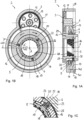
- FIGS. 4A and 4B show an actuator arrangement 2 according to the invention in a second embodiment, which corresponds to the embodiment according to the Figures 1A to 1C corresponds in many respects, so that reference is made to the above description with regard to the similarities. Identical or corresponding details are provided with the same reference numerals.
- a difference of the present embodiment according to the Figures 4A and 4B is that the locking ring 5 is not actuated, i.e. rotated, by the rotationally driven ramp ring 6, but by the axially supported ramp ring 8.
- the locking element 5 is connected to the second ramp ring 8 in a rotationally fixed manner via the connecting elements 18, so that both rotate together about the axis of rotation A.
- the friction surface pairing in the power path is formed between the rotationally drivable first ramp ring 6 and the second ramp ring 8.
- the first ramp ring 6 continues to rotate relative to them.
- the balls roll in the ball grooves 7, 9 in the direction of flatter sections, so that the first ramp ring 6 is pushed axially away from the second ramp ring 6.
- the connecting elements 18 are designed as one piece with the ring section 15, which engage in a form-fitting manner in corresponding recesses 37 of the ramp ring 8, so that both are connected to one another in a rotationally fixed manner.
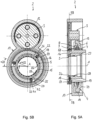
- FIGS 5A and 5B show an actuator arrangement 2 according to the invention in a further embodiment, which largely corresponds to the embodiment according to Figures 1A to 1C.
- FIG. 5B shows an actuator arrangement 2 according to the invention in a further embodiment, which largely corresponds to the embodiment according to Figures 1A to 1C.
- a difference of the present embodiment according to the Figures 5A and 5B is that the actuating ring 59 for rotating the locking ring 5 is not formed on the rotationally driven ramp ring, but is designed in the form of a separate intermediate ring.
- the intermediate ring 59 which can also be referred to as an intermediate gear, engages in the first toothing 12 of the drive gear 3 and is driven in rotation by it.
- the two toothings 12, 13 of the drive gear 3 have a different diameter or a different number of teeth, so that the first gear pair (12, 58) has a different transmission ratio than the second gear pair (13, 14).
- the intermediate gear 59 is mounted with an inner circumferential surface on a bearing seat 58 of the sleeve-shaped housing part 16 so as to be rotatable about the axis of rotation A.
- the intermediate gear 59 is driven in a correspondingly rotating manner, with which the locking ring 5 is in contact via friction surface pairs.
- the friction surface pairing is formed between the contact surfaces of the connecting elements 18 and an inner circumferential surface 19 of the intermediate gear 38.
- the spring preload causes the connecting elements 18 to come into frictional contact with the inner surface 19 of the intermediate wheel 59, so that when the intermediate wheel 59 rotates, they rotate with it until they hit one or the other rotation stop 23, 24, depending on the direction of rotation. After reaching the respective rotation stop, the intermediate wheel 59 continues to rotate, but the locking ring 5 remains in its rotational position and the connecting elements 18 slide along the inner surface 19 of the intermediate wheel.
- the ball ramp arrangement 4 is designed essentially as in the above embodiments. By rotating the first ramp ring 6 relative to the second ramp ring 8, the balls migrate to flatter areas so that the first ramp ring 6 is moved axially away from the second ramp ring 8, for example to actuate a friction clutch.
Landscapes
- Engineering & Computer Science (AREA)
- General Engineering & Computer Science (AREA)
- Mechanical Engineering (AREA)
- Physics & Mathematics (AREA)
- Electromagnetism (AREA)
- Mechanical Operated Clutches (AREA)
- Arrangement And Mounting Of Devices That Control Transmission Of Motive Force (AREA)
Description
- Die Erfindung betrifft eine Aktuatoranordnung für einen Antriebsstrang eines Kraftfahrzeugs. Die Erfindung betrifft ferner eine Kupplungsanordnung mit einer solchen Aktuatoranordnung sowie eine entsprechende Antriebsanordnung zum Antreiben eines Kraftfahrzeugs mit einer solchen Aktuatoranordnung.
- Generell werden Aktuatoren für eine Vielzahl von Funktionseinheiten in Antriebssträngen von Kraftfahrzeugen verwendet. Beispielsweise sind Aktuatoren für Kupplungen bekannt, die in Antriebssträngen von Kraftfahrzeugen eingesetzt werden, um eine Drehmomentübertragung selektiv herzustellen, zu unterbrechen oder auf einen gewünschten Wert einzustellen.
- Es sind mehrachsgetriebene Kraftfahrzeuge mit einem ersten Antriebsstrang zum permanenten Antreiben einer ersten Antriebsachse sowie einem zweiten Antriebsstrang zum optionalen Antreiben einer zweiten Antriebsachse bekannt. Dabei werden unterschiedliche Antriebskonzepte unterschieden, beispielsweise Kraftfahrzeuge mit Frontmotor, bei denen die Vorderachse permanent angetrieben wird und die Hinterachse zuschaltbar ist. Weiter gibt es Kraftfahrzeuge mit Frontmotor, bei denen die Hinterachse permanent angetrieben ist und die Vorderachse zuschaltbar ist. Schließlich sind Kraftfahrzeuge mit Heckmotor bekannt, bei denen die Hinterachse permanent angetrieben ist und die Vorderachse bedarfsweise zugeschaltet wird. Dabei kann die zuschaltbare Antriebsachse beispielsweise von einem Elektromotor antreibbar sein.
- Aus der gattungsbildenden
WO 2015/120909 A1 ist eine Kupplungsanordnung für einen Antriebsstrang eines Kraftfahrzeugs bekannt. Die Kupplungsanordnung umfasst eine Kupplung, welche zwei Wellen antriebsmäßig verbinden oder trennen kann, eine Bremse zum Bremsen der zweiten Welle und eine Betätigungsvorrichtung zum Betätigen der Kupplung und der Bremse. Die Betätigungsvorrichtung weist einen Rampenmechanismus auf, mit einem ersten Ring, der gegenüber dem ortsfesten Bauteil axial abgestützt ist, und einem zweiten Ring, der gegenüber dem ersten Ring axial verschiebbar ist, wenn einer von den Ringen relativ zum anderen verdreht wird. - Aus der
WO 2018/014950 A1 ist eine weitere Aktuatoranordnung mit einer Rampeneinheit zur Betätigung einer Kupplung im Antriebsstrang eines Kraftfahrzeugs bekannt. - Aus der
WO 2017/125135 A1 ist eine Kupplungsanordnung für ein Fahrzeug mit einer Trennkupplung zum Abschalten eines Antriebsstrangs und einer Kugelrampeneinheit zum Öffnen der Trennkupplung bekannt. - Aus der
DE 10 2018 124 681 A1 ist eine Vorrichtung zum Synchronisieren zwischen einer Welle und einem Losrad, mit einer Betätigungseinrichtung bekannt. - Aus der gegenüber diesem Dokument nachveröffentlichten
EP 3 543 554 A1 ist eine Kupplungsvorrichtung mit einer Rolleneinwegkupplung und einer Nockenkupplung bekannt. Die Rolleneinwegkupplung ist so gestaltet, dass die Drehbewegung eines Innenlaufrings der Kupplung in einer Richtung ermöglicht und in der anderen Richtung gesperrt wird. Die Nockenkupplung wirkt als Bremse, welche die Drehbewegung des Innenlaufrings in beiden Richtungen blockieren kann. Hierfür umfasst die Nockenkupplung einen axial bewegbaren Arbeitsring mit axialen Zapfen, die mit entsprechenden Ausnehmungen des Innenlaufrings formschlüssig in Eingriff gebracht werden können. - Aus der
DE 10 2008 063 904 A1 , entsprechendWO2010/078937 A1 , ist eine Antriebsanordnung für ein mehrachsgetriebenes Kraftfahrzeug bekannt. Die Antriebsanordnung umfasst eine Differentialeinheit, eine steuerbare Zuschaltkupplung zum antriebsmäßigen Verbinden mit einer Antriebseinheit sowie eine Sperrkupplung zum Sperren der Ausgleichsbewegung des Differentials. Die beiden Kupplungen sind koaxial zueinander angeordnet und mittels einer Kugelrampenanordnung betätigbar. Nach einer Ausführungsform ist vorgesehen, dass zuerst die Sperrkupplung und dann die Zuschaltkupplung betätigt wird. Nach einer anderen Ausführungsform ist vorgesehen, dass erst die Zuschaltkupplung und dann die Sperrkupplung betätigt wird. - Es sind Aktuatoren für Parksperren bekannt, die in Antriebssträngen von Kraftfahrzeugen eingesetzt werden, um ein Antriebsbauteil im Antriebsstrang optional zu blockieren, so dass das Kraftfahrzeug an einem unbeabsichtigten Wegrollen gehindert wird, wenn die Antriebsquelle kein Drehmoment zur Verfügung stellt.
- Aus der
DE 10 2005 022 926 B3 ist eine Antriebseinheit für ein Kraftfahrzeug bekannt, mit einem elektrischen Motor, einem Wechselgetriebe mit wenigstens zwei Gangstufen und einem Differential. Zur Betätigung der zwei Gangstufen ist eine Aktuatoranordnung vorgesehen, die eine drehend antreibbare Schaltwalze aufweist. Mittels der Schaltwalze wird eine Schaltmuffe betätigt, die eine erste Schaltkupplung oder alternativ eine zweite Schaltkupplung betätigt. Es ist ferner eine Parksperreneinrichtung vorgesehen, die koaxial zur Motorwelle angeordnet ist. Die Parksperreneinrichtung weist eine Sperrmuffe auf, die zwischen einer Freigabeposition und einer Sperrposition axial verschieblich gelagert ist. Die Sperrmuffe ist mittels der gleichen Aktuatoranordnung betätigbar, wie die Schaltkupplungen. - Es ist eine Aufgabe der vorliegenden Erfindung, eine multi-funktionale Aktuatoranordnung vorzuschlagen, die einfach und platzsparend aufgebaut ist. Eine weitere Aufgabe besteht darin, eine Kupplungsanordnung beziehungsweise Antriebsanordnung mit einer solchen Aktuatoranordnung vorzuschlagen.
- Zur Lösung wird eine Aktuatoranordnung für eine Kupplungsanordnung im Antriebsstrang eines Kraftfahrzeugs vorgeschlagen, umfassend: ein drehend antreibbares Antriebsrad; einen Sperrring, der in einem ortsfesten Gehäuse um eine Drehachse drehbar gelagert ist und der mit dem Antriebsrad über einen Leistungspfad antriebsverbunden ist, wobei der Sperrring von dem Antriebrad von einer ersten Drehposition gegen einen Drehanschlag in eine zweite Drehposition drehbar ist; wobei im Leistungspfad zwischen dem Antriebsrad und dem Sperrring zumindest eine Reibflächenpaarung vorgesehen ist, über die ein Drehmoment unter Ausnutzung von Reibkräften auf den Sperrring übertragbar ist; einen von dem Antriebsrad drehend antreibbaren ersten Rampenring und einen zweiten Rampenring, wobei der erste Rampenring und der zweite Rampenring gegeneinander axial abgestützt sind, und ausgestaltet sind, um eine relative Drehbewegung in eine Axialbewegung umzusetzen; wobei der Rampenring, nachdem der Sperrring den Drehanschlag erreicht hat, vom Antriebsrad weiter drehend antreibbar ist.
- Ein Vorteil ist, dass die Aktuatoranordnung zwei Funktionen realisieren kann, nämlich das Betätigen des Sperrrings, beispielsweise für eine Freilaufkupplung, sowie das Betätigen eines weiteren Betätigungsglieds, beispielsweise für eine Reibungskupplung. Damit benötigt die vorgeschlagene Aktuatoranordnung nur eine geringe Anzahl von Bauteilen, was sich günstig auf den erforderlichen Bauraum und die Fertigungs- und Montagekosten auswirkt. Außerdem wird zusätzlich zur mechanischen Integration einer ersten und einer zweiten Betätigungsfunktion entsprechend auch eine elektrische Integration erreicht, was sich aufgrund einer geringeren Anzahl von elektrischen Schnittstellen ebenfalls günstig auf die Zuverlässigkeit und Lebensdauer der Anordnung auswirkt.
- Nach einer Ausführung kann der Sperrring einen Ringabschnitt und zumindest ein hiervon abstehendes Verbindungselement zum Einleiten eines Drehmoments in den Sperrring aufweisen. Mit dem Ringabschnitt kann der Sperrring in dem ortsfesten Gehäuse begrenzt drehbar gelagert sein. Es können ein, zwei, drei oder mehr Verbindungselemente vorgesehen sein, die insbesondere gleichmäßig über den Umfang verteilt sind und von dem Ringabschnitt nach radial außen abstehen können. Es versteht sich, dass sofern vorliegend auf ein oder zumindest ein Verbindungsabschnitt Bezug genommen wird, die beschriebenen Merkmale auch für jeden weiteren Verbindungsabschnitt gelten können.
- Das ortsfeste Gehäuse kann einen hülsenförmigen Abschnitt aufweisen, in dem der Sperrring um die Drehachse drehbar gelagert ist, wobei der hülsenförmige Abschnitt zumindest einen radialen Durchbruch aufweist, in den das zumindest eine Verbindungselement des Sperrrings eingreift. Vorzugsweise ist je Verbindungselement ein Durchbruch vorgesehen.
- Nach einer ersten Ausführungsform des Sperrelements ist das zumindest eine Verbindungselement federnd gegen einen vom Antriebsrad drehend antreibbaren Betätigungsring beaufschlagt und steht mit diesem in Reibkontakt. Der Betätigungsring ist relativ zum Sperrring verdrehbar, wobei durch Drehen des Betätigungsrings der Sperrring aufgrund der Reibwirkung mitgenommen wird, bis der Sperrring gegen einen Drehanschlag zur Anlage kommt. Nach Drehstopp des Sperrrings dreht der Betätigungsring weiter, wobei das zumindest eine Verbindungselement an der Kontaktfläche des Betätigungsrings entlanggleitet. In einer weiteren Konkretisierung kann das zumindest eine Verbindungselement über ein Federelement gegen einen Grundkörper des Sperrrings federnd abgestützt sein. Der Grundkörper des Sperrrings ist insbesondere ringförmig gestaltet und hat über den Umfang verteilt vorzugsweise mehrere radiale Bohrungen, in denen jeweils ein Verbindungselement federnd abgestützt einsitzt. Ein Verbindungselement und zugehöriges Federelement können als separate Elemente ausgebildet sein, wobei es ebenso möglich ist, dass diese fest miteinander verbunden und/oder einteilig gestaltet sind.
- Der Betätigungsring, mit dem der Sperrring über die Verbindungselemente in Reibkontakt ist, kann prinzipiell ein beliebiges Bauteil im Leistungspfad zwischen dem Antriebsrad und dem Sperrring sein. Nach einer ersten Option kann der Betätigungsring drehfest mit dem drehend antreibbaren ersten Rampenring verbunden sein, insbesondere einteilig mit diesem gestaltet sein. Dabei ist die Reibflächenpaarung zum drehenden Antreiben des Sperrrings jeweils zwischen einer Kontaktfläche eines Verbindungselements und einer Anlagefläche des ersten Rampenrings gebildet. Nach einer zweiten Option kann der Betätigungsring in Form eines Zwischenrads gestaltet sein, das von dem Antriebsrad um die Drehachse drehend antreibbar ist. Dabei ist die Reibflächenpaarung jeweils zwischen einer Kontaktfläche eines Verbindungselements und einer Anlagefläche des Zwischenrads gebildet. Bei dieser Ausführung kann das Antriebsrad eine erste Verzahnung zum Antreiben des ersten Rampenrings und eine zweite Verzahnung zum Antreiben des Zwischenrads aufweisen, wobei die beiden Verzahnungen einen unterschiedlichen Durchmesser beziehungsweise eine unterschiedliche Zähnezahl haben.
- Nach einer zweiten Ausführungsform kann das Sperrelement über das zumindest eine Verbindungselement drehfest mit dem zweiten Rampenring verbunden sein, so dass beide gemeinsam drehen. In diesem Fall ist die Reibflächenpaarung im Leistungspfad zwischen dem drehend antreibbaren ersten Rampenring und dem zweiten Rampenring gebildet. Wenn der erste Rampenring vom Antriebsrad verdreht wird, dreht sich der zweite Rampenring und der damit drehfest verbundene Sperrring zunächst mit, bis der Sperring gegen einen Drehanschlag des ortsfesten Gehäuses stößt. Nach diesem Drehstopp des Sperrrings und des damit verbundenen zweiten Rampenrings dreht der erste Rampenring gegenüber diesen weiter, wobei die Drehbewegung des ersten Rampenrings relativ zum zweiten Rampenring zu einer axialen Spreizung der Kugelrampenanordnung führt.
- Für alle oben genannten Ausführungen gilt insbesondere, dass der erste Rampenring und der zweite Rampenring mittelbar über Kugeln gegeneinander axial abgestützt sind, die in entsprechenden Kugelrillen des ersten und zweiten Rampenrings laufen. Die Kugelrillen können so gestaltet sein, dass sie jeweils in Draufsicht auf die Stirnflächen in gleicher Umfangsrichtung eine abnehmende Tiefe haben, wobei in Paaren von einander gegenüberliegenden Kugelrillen jeweils eine Kugel aufgenommen ist, über die sich der erste und der zweite Ring aneinander abstützen. Bei relativer Verdrehung des einen Rampenrings relativ zum anderen Rampenring wandern die Kugeln, je nach Drehrichtung, in tiefere oder flachere Rillenbereiche, so dass sich die beiden Rampenringe entweder axial annähern oder voneinander entfernen. Alternativ zur Ausgestaltung mit Kugelrillen können der erste Rampenring und der zweite Rampenring auch unmittelbar gegeneinander über entsprechende Gleitflächen axial abgestützt sein.
- Nach einer möglichen Ausführungsform ist der zweite Rampenring gegen das ortsfeste Gehäuse axial abgestützt ist, wobei der erste Rampenring durch drehendes Antreiben mittels des Antriebsrads aus einer ersten Axialposition, in welcher der erste Rampenring an den zweiten Rampenring axial angenähert ist, in eine zweite Axialposition, in welcher der erste Rampenring vom zweiten Rampenring axial beabstandet ist, bewegbar ist. Der erste Rampenring kann an seiner vom zweiten Rampenring abgewandten Seite eine Betätigungsfläche zum axialen Beaufschlagen einer Reibungskupplung aufweisen.
- Die Aufgabe wird ferner gelöst durch eine Kupplungsanordnung mit einer Aktuatoranordnung, die nach zumindest einer der oben genannten Ausführungsformen gestaltet ist, umfassend: eine Formschlusskupplung mit einem ersten Kupplungselement und einem hierzu axial bewegbaren zweiten Kupplungselement, wobei das zweite Kupplungselement in einer Schließstellung drehfest mit dem ersten Kupplungselement verbunden ist und in einer Offenstellung vom ersten Kupplungselement entkoppelt ist, um gegenüber diesem frei drehbar zu sein; eine Reibungskupplung zur variablen Drehmomentübertragung zwischen einem ersten Kupplungsteil und einem zweiten Kupplungsteil; wobei der Sperrring der Aktuatoranordnung in der ersten Drehposition eine Axialbewegung des zweiten Kupplungselements der Formschlusskupplung blockiert, wobei die Formschlusskupplung geschlossen ist; wobei der Sperrring, durch Verdrehen in die zweite Drehposition mittels des Antriebsrads, das zweite Kupplungselement der Formschlusskupplung axial freigibt, so dass die Formschlusskupplung geöffnet wird; wobei bei weiterem Verdrehen des Antriebsrads der Sperrring in der zweiten Drehposition verbleibt und die Reibungskupplung von dem drehend antreibbaren ersten Rampenring im Schließsinn beaufschlagt wird.
- Nach einer Ausführungsform kann das erste Kupplungselement der Formschlusskupplung im ortsfesten Gehäuse im Drehsinn abgestützt und axial bewegbar sein. Durch axiales Verstellen des ersten Kupplungselements wird die Blockade des Sperrrings aufgehoben, so dass die beiden Kupplungselemente frei gegeneinander drehen können. Insofern kann das erste Kupplungselement der Formschlusskupplung auch als Stellelement oder Blockierelement, und die Formschlusskupplung auch als Freilaufkupplung bezeichnet werden. Das zweite Kupplungselement der Formschlusskupplung kann drehfest und axial fest mit einer Welle verbunden sein.
- Die Reibungskupplung kann mit dem ersten Reibungs-Kupplungsteil drehfest und axial beweglich verbundene erste Lamellen und mit dem zweiten Reibungs-Kupplungsteil drehfest und axial beweglich verbundene zweite Lamellen aufweisen, wobei die ersten und zweiten Lamellen insbesondere axial abwechselnd angeordnet sind und gemeinsam ein Lamellenpaket bilden. Das Lamellenpaket ist von einer Druckplatte axial beaufschlagbar, die von dem ersten Rampenring betätigbar ist, wobei zwischen dem ersten Rampenring und der Druckplatte ein Axiallager zur Drehentkopplung vorgesehen ist.
- Nach einer Ausführungsform kann ein Umlaufrädergetriebe vorgesehen sein mit einem Getriebeeingangsteil und ein Eingangsrad aufweist, das von der elektrischen Maschine um eine Drehachse (A) drehend antreibbar ist, einem Stützrad, das koaxial zum Eingangsrad drehbar angeordnet ist und das mit dem Stützelement der Formschlusskupplung drehfest verbunden ist, wobei das Stützrad in der Schließstellung der Formschlusskupplung am ortsfesten Bauteil im Drehsinn abgestützt ist, und in einer Offenstellung der Formschlusskupplung frei drehbar ist, einer Mehrzahl von Planetenrädern, die mit dem Eingangsrad und dem Stützrad in Verzahnungseingriff sind, und einem Trägerelement, auf dem die Planetenräder drehbar gelagert sind und das um die Drehachse drehend antreibbar ist, um Drehmoment auf eine nachgelagerte Antriebseinheit zu übertragen, wobei die Reibungskupplung im Leistungspfad zwischen einem der Teile Eingangsrad, Stützrad und Trägerelement und einem anderen der Teile Eingangsrad, Stützrad und Trägerelement angeordnet ist.
- Es ist insbesondere vorgesehen, dass in Schließstellung der Formschlusskupplung und Offenstellung der Reibungskupplung ein erstes Übersetzungsverhältnis zwischen dem Antriebsrad und dem Trägerelement gebildet ist, und, dass in Offenstellung der Formschlusskupplung mittels der Reibungskupplung ein variables Drehmoment zwischen dem Antriebsrad und dem Trägerelement übertragbar ist, wobei bei vollständig geschlossener Reibungskupplung ein zweites Übersetzungsverhältnis zwischen dem Antriebsrad und dem Trägerelement gebildet ist.
- Das Trägerelement des Umlaufrädergetriebes kann mit einer nachgelagerten Leistungsverzweigungseinheit antriebsverbunden sein, die beispielsweise in Form eines Differentialgetriebes gestaltet sein kann. Das Differentialgetriebe teilt die eingeleitete Drehbewegung auf zwei Ausgangsteile zum Antreiben einer jeweiligen Seitenwelle auf. Anstelle eines Differentialgetriebes kann auch eine Doppelkupplungseinheit als Leistungsverzweigungseinheit verwendet werden (Twin-Kupplung).
- Bevorzugte Ausführungsformen werden nachstehend anhand der Zeichnungsfiguren erläutert. Hierin zeigt:
- Figur 1A
- eine erfindungsgemäße Aktuatoranordnung für eine Kupplungsanordnung im Antriebsstrang eines Kraftfahrzeugs in einer ersten Ausführungsform im Längsschnitt;
- Figur 1B
- die Aktuatoranordnung aus
Figur 1A gemäß Schnittlinie 1B-1B; - Figur 1C
- ein Detail der Aktuatoranordnung aus
Figur 1B in vergrößerter Darstellung; - Figur 2A
- eine Kupplungsanordnung mit einer Formschlusskupplung und einer Reibungskupplung sowie mit einer erfindungsgemäßen Aktuatoranordnung gemäß
Figur 1A und 1B im Längsschnitt; - Figur 2B
- die Kupplungsanordnung aus
Figur 2A im Halblängsschnitt mit geschlossener Formschlusskupplung; - Figur 2C
- die Kupplungsanordnung aus
Figur 2A im Halblängsschnitt mit geöffneter Formschlusskupplung; - Figur 3
- schematisch eine Antriebssanordnung mit einer erfindungsgemäßen Aktuatoranordnung gemäß
Figur 1 ; - Figur 4A
- eine erfindungsgemäße Aktuatoranordnung für eine Kupplungsanordnung im Antriebsstrang eines Kraftfahrzeugs in einer zweiten Ausführungsform im Längsschnitt;
- Figur 4B
- die Aktuatoranordnung aus
Figur 4A gemäß Schnittlinie 4B-4B; - Figur 5A
- eine erfindungsgemäße Aktuatoranordnung für eine Kupplungsanordnung im Antriebsstrang eines Kraftfahrzeugs in einer weiteren Ausführungsform im Längsschnitt; und
- Figur 5B
- die Aktuatoranordnung aus
Figur 5A gemäß Schnittlinie 5B-5B. - Die
Figuren 1 bis 3 werden nachstehend gemeinsam beschrieben. Es ist eine erfindungsgemäße Aktuatoranordnung 2 zum Aktuieren von Kupplungen im Antriebsstrang eines Kraftfahrzeugs gezeigt. Die Aktuatoranordnung 2 umfasst ein Antriebsrad 3, das von einer Aktuator-Antriebseinheit (nicht dargestellt) antreibbar ist, eine Rampenringanordnung 4, die ausgestaltet ist, um eine vom Antriebsrad 3 eingeleitete Drehbewegung in eine Axialbewegung umzuwandeln, und einen Sperrring 5, der mit dem Antriebsrad 3 mittelbar antriebsverbunden ist, um von diesem um die Drehachse A verdreht zu werden. - Die Rampenringanordnung 4 ist vorliegend in Form einer Kugelrampeneinheit gestaltet, die einen ersten Rampenring 6 mit mehreren umfangsverteilten ersten Kugelbahnen 7, einen zweiten Rampenring 8 mit mehreren umfangsverteilten zweiten Kugelbahnen 9 und mehrere umfangsverteilten Kugeln, die jeweils zwischen einer ersten Kugelbahn 7 und einer zweiten Kugelbahn 9 angeordnet und in diesen geführt sind. Die Kugeln liegen außerhalb der gezeigten Schnittebene und sind daher nicht dargestellt.
- Das Aktuator-Antriebsrad 3 ist mit dem ersten Rampenring 6 antriebsverbunden, um dieses um die Drehachse A zu verdrehen. Hierfür hat das Antriebsrad 3 eine erste Verzahnung 12 zur Einleitung einer Drehbewegung von einer Antriebsquelle sowie eine zweite Verzahnung 13, die mit einer Gegenverzahnung 14 des ersten Rampenrings 6 in Eingriff ist.
- Der zweite Rampenring 8 ist gegen ein ortsfestes Bauteil 16 axial abgestützt und drehfest gehalten. Das ortsfeste Bauteil 16 ist vorliegend als hülsenförmiger Abschnitt eines Gehäuses 17 gestaltet. Durch eine relative Drehbewegung des ersten Rampenrings 6 gegenüber dem drehfesten zweiten Rampenring 8 laufen die Kugeln in den Kugelrillen 7, 9 in Umfangsrichtung, wobei - wenn die Kugeln in flachere Abschnitte der Kugelrillen 7, 9 laufen - der erste Rampenring 6 vom zweiten Rampenring 8 axial wegbewegt wird.
- Der Sperrring 5 hat mehrere über den Umfang verteilte Verbindungselemente 18, die mit einer Innenumfangsfläche 19 eines Betätigungsrings 59 des ersten Rampenrings 6 in Reibkontakt stehen. Bei der vorliegenden Ausführungsform ist der Betätigungsring 59 mit dem Rampenring 6 gestaltet. Es sind vorliegend genau drei regelmäßig über den Umfang verteilte Verbindungselemente 18 vorgesehen, wobei auch eine hiervon abweichende Anzahl möglich ist. Die Verbindungselemente 18 erstrecken sich nach radial außen durch umfangsverteilte Öffnungen 20 des ortsfesten Bauteils 16 hindurch. Die Öffnungen 20 haben eine Umfangserstreckung α20, die größer ist, als eine Umfangserstreckung α22 der Verbindungselemente 18 beziehungsweise der Stützelemente 22, in denen die Verbindungselemente 18 aufgenommen sind, so dass der Sperrring 5 relativ zum ortsfesten Bauteil 16 begrenzt drehbar ist. Dabei bilden die Seitenwände 23, 24 der Öffnungen 20 Drehanschläge, gegen welche die Stützelemente 22 sich in Umfangsrichtung abstützen können. Es ist insbesondere in der unteren Schnitthälfte von
Figur 1A erkennbar, dass die Öffnungen 20 vorliegend in Form von Schlitzen gestaltet sind, die sich von einem freien Ende 29 des hülsenförmigen Gehäuseteils 16 bis zu einem Axialanschlag 33 erstrecken, gegen den der Sperrring 5 axial abgestützt ist. - Bei der vorliegenden Ausführungsform sind die Verbindungselemente 18 jeweils über ein Federelement 25 gegen das jeweilige Stützelement 22 in radiale Richtung federnd abgestützt. Durch die Federvorspannung werden die Verbindungselemente 18 in Reibkontakt mit der Innenfläche 19 des ersten Rings 6 gebracht, so dass sie bei Drehung des ersten Rings 6 mit diesem mitdrehen, bis sie je nach Drehrichtung gegen den einen oder anderen Drehanschlag 23, 24 in Anlage kommen. Nach Erreichen des Drehanschlags dreht der erste Ring 6 weiter, wobei der Stellring 5 jedoch in seiner Drehposition verbleibt und die Verbindungselemente 18 an der Innenfläche 19 des ersten Rings 6 entlanggleiten.
- Der Sperrring 5 hat ferner einen Ringabschnitt 15 mit einer Innenverzahnung 26. Axial an den Sperrring angrenzend ist ein mit dem hülsenförmigen Gehäuseteil 16 verbundenes zweites hülsenförmiges Gehäuseteil 27 vorgesehen. Das zweite hülsenförmige Gehäuseteil 27 weist eine zweite Innenverzahnung 28 auf, die gleich gestaltet ist, wie die Innenverzahnung 26 des Sperrrings 5.
- Durch Verdrehen des Rampenrings 6 wird der Sperrring 5 über die Verbindungselemente 18 um einen begrenzten Drehweg mitgedreht. Dabei wird der Sperrring 5 aus ersten Drehstellung Pr1, in der dessen Innenverzahnung 26 gegenüber der Innenverzahnung 28 des Gehäuseteils 27 in Umfangsrichtung versetzt ist (Zahn-auf-Lücke-Stellung) in eine zweite Drehstellung Pr2 bewegt, in der die beiden Innenverzahnungen 26, 28 miteinander fluchten (Zahn-auf-Zahn-Stellung). In der ersten Drehstellung Pr1 liegen zumindest einige der Zähne des Sperrrings 5 in Umfangsbereichen von Zahnlücken des Gehäuseteils 27, so dass eine Axialbewegung eines mit dem Gehäuseteil 27 in Verzahnungseingriff befindlichen Bauteils 32 durch den Sperrring 5 blockiert wird. In der zweiten Drehstellung Pr2 bildet die Verzahnung 26 des Sperrrings 5 eine natürliche Fortsetzung der Verzahnung 28 des Gehäuseteils 27, so dass das Bauteil 32, das mit seiner korrespondierenden Außenverzahnung in die Innenverzahnung 28 des Gehäuseteils 27 eingreift, nunmehr axial in die Innenverzahnung 26 des Sperrrings 5 verschoben werden kann.
- Die Kugelrampenanordnung 4 ist insbesondere so gestaltet, dass der Stellring 6 bei relativer Verdrehung gegenüber dem Stützring 8 in Richtung R1 soweit, bis der Sperrring 5 seinen Endanschlag 24 erreicht hat (zweite Drehposition Pr2), seine axiale Position Pa1 beibehält. Erst nachdem der Stellring 5 seine zweite Drehposition Pr2 eingenommen hat und das Bauteil 32 in die Verzahnung 26 des Sperrrings 5 eingreift, wandern die Kugeln der Kugelrampenanordnung 4 in flachere Bereiche, so dass der Stellring 6 axial vom Stützring 8 in Richtung einer zweiten axialen Position Pa2 wegbewegt wird.
- Die Aktuatoranordnung 2 kann auf diese Weise zwei Funktionen realisieren, nämlich das Betätigen des Sperrrings 5, um eine Axialbewegung des Bauteils 32 wahlweise zu blockieren oder freizugeben, sowie das Betätigen eines weiteren Betätigungsglieds 49 mittels des axial bewegbaren Stellrings 6.
- Die
Figuren 2A bis 2C zeigen eine erfindungsgemäße Kupplungsanordnung 11 mit einer erfindungsgemäßen Aktuatoranordnung 2 gemäßFigur 1 . Die Kupplungsanordnung 11 umfasst eine erste Kupplung 30, die in Form einer Formschlusskupplung gestaltet ist, und eine zweite Kupplung 40, die in Form einer Reibungskupplung gestaltet ist. - Die Formschlusskupplung 30 umfasst ein erstes Kupplungsteil 31, das drehfest mit einer Welle 34 verbunden ist, und das Bauteil 32 als zweites Kupplungsteil. Das erste Kupplungsteil ist mit einem Endabschnitt gegen eine Wellenschulter der Welle 34 axial abgestützt. Die Welle 34 mit dem darauf angebrachten ersten Kupplungsteil 31 ist mittels eines Lagers 35 im Gehäuseteil 16 um die Drehachse A drehbar gelagert und axial abgestützt. Ein Lagerinnenring des Lagers 35 ist zwischen einer Schulter des Kupplungsteils 31 und einem Axialsicherungsring axial abgestützt. Der Lageraußenring ist in dem Gehäuseteil 16 aufgenommen und mittels eines weiteren Axialsicherungsring axial abgestützt. Das zweite Kupplungsteil 32 hat eine Außenverzahnung 36, die mit der Innenverzahnung 28 des Gehäuseteils 16 zur Übertragung beziehungsweise Abstützung eines Drehmoments in Verzahnungseingriff ist, wobei das zweite Kupplungsteil 32 gegenüber dem Gehäuseteil 16 axial bewegbar ist.
- Die
Figur 2B zeigt die Formschlusskupplung 30 in geschlossener Stellung, bei der das erste Kupplungsteil 31 und das zweite Kupplungsteil 32 miteinander in formschlüssigem Eingriff sind. In diesem Zustand ist die Welle 34 über das erste Kupplungsteil 31, das hiermit in Eingriff befindliche zweite Kupplungsteil 32 an dem Gehäuseteil 16 im Drehsinn abgestützt. - Zum Öffnen der Kupplung 31 wird, wie oben beschrieben, der Sperrring 5 durch Verdrehen des Rampenrings 6 von der ersten Drehstellung Pr1, in welcher die Sperrring-Innenverzahnung 26 gegenüber der Gehäuse-Innenverzahnung 28 in Drehrichtung versetzt ist, in die zweite Drehstellung Pr2 bewegt, in der die beiden Innenverzahnungen 26, 28 miteinander fluchten. Auf diese Weise wird die axiale Blockierung des Kupplungsteils 32 aufgehoben, welches nunmehr über das axiale Ende der Gehäuse-Innenverzahnung 28 hinaus axial in den Sperrring 5 verschoben werden kann.
- Die Axialkraft zum Bewegen des Kupplungsteils 32 wird dadurch bewirkt, dass die Innenverzahnung 28 des Gehäuseteils 16 und entsprechend die Außenverzahnung 36 als Schrägverzahnungen gestaltet sind. Dabei sind die Schrägverzahnungen so gestaltet, dass ein in die Welle 34 eingeleitetes und entsprechend zwischen dem ersten Kupplungsteil 31 und dem zweiten Kupplungsteil 32 wirksames Drehmoment eine Axialbewegung des zweiten Kupplungsteils 32 im Öffnungssinn bewirkt.
- Durch die Axialverschiebung kommt das Kupplungsteil 32 mit seiner Außenverzahnung 36 in Eingriff mit der Innenverzahnung 26 des Sperrrings 5 ein. Ferner wird das zweite Kupplungsteils 32 außer Eingriff vom ersten Kupplungsteil 31 gebracht, so dass das erste Kupplungsteil 31 und die damit verbundene Welle 34 gegenüber dem zweiten Kupplungsteil 32 beziehungsweise dem Gehäuseteil 16 frei drehen können. Die geöffnete Stellung der Formschlusskupplung 30 ist in
Figur 2C gezeigt, in der erkennbar ist, dass das zweite Kupplungsteil 32 gegenüber dem ersten Kupplungsteil 31 axial verschoben ist und die Formschlussmittel entsprechend außer Eingriff sind. - Die zweite Kupplung 40 ist vorliegend als Reibungskupplung gestaltet, die ein erstes Kupplungsteil 41 und ein hiermit zur variablen Drehmomentübertragung verbindbares zweites Kupplungsteil 42 umfasst. Das erste Kupplungsteil 41 bildet einen ersten Lamellenträger 43, mit dem erste Lamellen 44 drehfest und axial beweglich verbunden sind. Das zweite Kupplungsteil 42 bildet einen zweiten Lamellenträger 45, mit dem zweite Lamellen 46 axial beweglich und drehfest verbunden sind. Die ersten und zweiten Lamellen 44, 46, die auch als Außenlamellen und Innenlamellen bezeichnet werden können, sind axial abwechselnd angeordnet und bilden gemeinsam ein Lamellenpaket 47. Das Lamellenpaket 47 ist in eine erste axiale Richtung über Stützplatte 48 am zweiten Kupplungsteil 42 axial abgestützt. Zum Beaufschlagen des Lamellenpakets 47 ist eine Druckplatte 49 vorgesehen, welche von der Kugelrampenanordnung 4 axial bewegbar ist.
- Hierfür ist zwischen dem ersten Rampenring 6 und der Druckplatte 49 ein Kraftübertragungsmechanismus 50 vorgesehen, welcher eine axiale Bewegung des ersten Rampenrings 6 auf die Druckplatte 49 überträgt, so dass das Lamellenpaket 47 im Schließsinn der Kupplung 40 beaufschlagt wird. Der Kraftübertragungsmechanismus 50 umfasst einen Stützkörper 51, der gegen eine Stirnfläche des Rampenrings 6 axial abgestützt ist, ein Axiallager 52 zur Drehentkopplung einer relativen Drehbewegung des ersten Kupplungsteils 41 gegenüber dem Rampenring 6, ein Zwischenelement 53, das an dem Axiallager 52 axial abgestützt und gegenüber diesem drehbar ist, sowie mehrere über den Umfang verteilte Druckelemente 54, die mit dem Zwischenelement 53 verbunden sind und gemeinsam mit diesem axial bewegt werden. Die Druckelemente 54 erstrecken sich durch umfangsverteilte Öffnungen 55 (gestrichelt dargestellt) in einer Seitenwand 56 des ersten Kupplungsteils 41 in dieses hinein und sind mit der Druckplatte 49 in Kontakt, um diese in Richtung Lamellenpaket 47 zu beaufschlagen. Das erste Kupplungsteil 41 ist mittels eines Lagers 57 in einem Lagerabschnitt 58 des Gehäuseteils 16 um die Drehachse A drehbar gelagert.
- Wie oben beschrieben, ist die Kugelrampenanordnung 4 so gestaltet, dass nachdem der Stellring 6. & seine zweite Drehposition Pc2 eingenommen hat und die Formschlusskupplung 30 geöffnet ist, die Kugeln in flachere Bereiche laufen. Hierdurch wird der Stellring 6 axial vom Stützring 8 weg in Richtung der Reibungskupplung 40 bewegt, um diese zu schließen. Durch entsprechende Steuerung des Aktuator-Antriebs kann die Drehposition des Rampenrings 6 und damit das von der Reibungskupplung 40 zu übertragende Drehmoment nach Bedarf variabel eingestellt werden. Zum erneuten Öffnen der Kupplung 40 bei abgeschaltetem Aktuator können ein oder mehrere Rückstellfedern vorgesehen sein, welche eine Bewegung der Druckplatte 49 in Richtung Kugelrampenanordnung 4 bewirken. Die Rückstellfeder (nicht dargestellt) kann beispielsweise zwischen dem Zwischenelement 52 und der Kupplungswand 56 angeordnet sein.
- Die
Figur 3 zeigt eine erfindungsgemäße Antriebsanordnung 21 mit einer erfindungsgemäßen Kupplungsanordnung 11 gemäß denFiguren 2A bis 2C , beziehungsweise mit einer erfindungsgemäßen Aktuatoranordnung 2 gemäßFigur 1 , in schematischer Darstellung. Aufbau und Funktionsweise der Aktuatoranordnung 2 und der Kupplungsanordnung 11 gemäßFigur 3 entsprechen den Ausführungen gemäß denFiguren 1 und2 , so dass diesbezüglich abkürzend auf die obige Beschreibung Bezug genommen wird. Dabei sind gleiche beziehungsweise einander entsprechende Bauteile mit den gleichen Bezugszeichen versehen, wie bei den obigen Figuren. - Die Antriebsanordnung 21 umfasst eine Getriebeeinheit 60 und eine dieser im Leistungspfad nachgelagerte Leistungsverzweigungseinheit 70.
- Die Getriebeeinheit 60 weist insbesondere zwei Übersetzungsstufen mit unterschiedlichen Übersetzungsverhältnissen auf. Hierfür umfasst die Getriebeeinheit 60 ein Umlaufrädergetriebe mit einem drehend antreibbaren Eingangsteil 62 mit einem Hohlrad 63 als Eingangsrad, einem hierzu koaxial angeordneten Stützrad 64, einer Mehrzahl von Planetenrädern 65, die mit dem Hohlrad 63 und dem Stützrad 64 in Verzahnungseingriff sind, und einem Trägerelement 66, auf dem die Planetenräder 65 drehbar gelagert sind.
- Das Eingangsteil 62 weist eine Außenverzahnung auf, die mit einem Antriebsrad 61 einer Antriebswelle zur Übertragung einer Drehbewegung in Eingriff steht. Die Antriebswelle wird von einer elektrischen Maschine (nicht dargestellt) drehend angetrieben. Das Antriebsrad 61 und das Eingangsteil 62 wirken als Untersetzungsgetriebe zusammen, das eine Drehbewegung vom Schnellen ins Langsame übersetzt. Somit dreht Eingangsteil 62 langsamer als die Antriebswelle. Das Getriebeeingangsteil 62 ist fest mit dem ersten Kupplungsteil 41 verbunden, so dass beide gemeinsam um die Drehachse A rotieren. Der Planetenträger 66 ist fest mit dem zweiten Kupplungsteil 42 verbunden, so dass diese gemeinsam um die Drehachse A rotieren. Durch Betätigung der Reibungskupplung 40 im Schließsinne wird die Drehzahl des Trägerelements 66 an die Drehzahl des Eingangsteils 62 angepasst.
- Das Stützrad 64, das koaxial zum Hohlrad 63 angeordnet ist, ist mit der Welle 34 und damit mit dem ersten Kupplungsteil 31 der Formschlusskupplung 30 drehfest verbunden. Somit ist das Stützrad 64 in der Schließstellung der Formschlusskupplung 30 am ortsfesten Bauteil 16 im Drehsinn abgestützt, und kann in der Offenstellung der Formschlusskupplung 30 frei drehen.
- Die Planetenräder 65 sind an dem Planetenträger 44 drehbar gelagert und kämmen mit dem Hohlrad 63 und mit dem Stützrad 64. Die Verzahnungen der Planetenräder 65 mit dem Hohlrad 63 und mit dem Stützrad 64 sind vorzugsweise als Schrägverzahnungen ausgeführt. Der Planetenträger 66 ist fest mit einem Ausgangsteil 67 des Getriebes 60 verbunden.
- In Schließstellung der Formschlusskupplung 30 und Offenstellung der Reibungskupplung 40 ist ein erstes Übersetzungsverhältnis zwischen dem Eingangsteil 62 und dem Trägerelement 66 gebildet. Dabei ist das Stützrad 64 über die Formschlusskupplung 30 drehfest mit dem Gehäuse 17 verbunden, während die zweite Reibungskupplung 40 das Hohlrad 63 von dem Stützrad 64 trennt. Die Drehbewegung des Hohlrads 63 wird somit über die um das Stützrad 64 umlaufenden Planetenräder 65 auf den Planetenträger 66 übertragen. Das Planetengetriebe 60 wirkt als Untersetzungsgetriebe, das eine Drehbewegung vom Schnellen ins Langsame übersetzt. Somit dreht der Planetenträger 66 langsamer als das Hohlrad 63, wobei ein erstes Übersetzungsverhältnis i1 gegeben ist.
- Für die zweite Übersetzungsstufe trennt die Formschlusskupplung 30 das Stützrad 64 von dem Gehäuse 17, während die Reibungskupplung 40 ein Drehmoment vom Eingangsteil 62 auf das Trägerelement 66 überträgt. Dadurch wird das Planetengetriebe mit steigendem Schließgrad der Kupplung 40 zunehmend blockiert. Mit dem frei drehbaren Stützrad 64 wird so die Drehbewegung des Hohlrads 63 über die Planetenräder 65, die nicht um das Stützrad 64 umlaufen können, auf den Planetenträger 66 übertragen. Bei vollständig geschlossener Reibungskupplung 40 sind die Drehzahlen des Eingangsteils 62 beziehungsweise Hohlrads 63 einerseits und des Planetenträgers 66 beziehungsweise Ausgangsteils 67 identisch. Dabei ist ein zweites Übersetzungsverhältnis gegeben, das sich vom ersten Übersetzungsverhältnis unterscheidet. Dadurch, dass die zweite Kupplung 40 als Reibungskupplung gestaltet ist, können Drehmoment beziehungsweise Drehzahl variabel nach Bedarf eingestellt werden.
- Das Ausgangsteil 67 des Planetengetriebes treibt über ein Antriebsrad 68 ein Eingangsteil 71 der Leistungsverzweigungseinheit 70 an. Die Leistungsverzweigungseinheit 70 ist vorliegend in Form eines Differentialgetriebes gestaltet, das eine eingeleitete Drehbewegung auf zwei Ausgangsteile 72, 73 zum Antreiben einer jeweiligen Seitenwelle 74, 75 aufteilt. Das Eingangsteil 71 ist in Form eines um die Drehachse B drehbaren Differentialkorbs gestaltet, in dem mehrere Differentialräder 76 drehbar gelagert sind, die mit den beiden Ausgangsrädern 72, 73 kämmen.
- Die
Figuren 4A und 4B zeigen eine erfindungsgemäße Aktuatoranordnung 2 in einer zweiten Ausführungsform, die der Ausführungsform gemäß denFiguren 1A bis 1C in weiten Teilen entspricht, so dass hinsichtlich der Gemeinsamkeiten auf die obige Beschreibung Bezug genommen wird. Dabei sind gleiche beziehungsweise einander entsprechende Einzelheiten mit gleichen Bezugszeichen versehen. - Ein Unterschied der vorliegenden Ausführungsform gemäß den
Figuren 4A und 4B ist, dass der Sperrring 5 nicht von dem drehend antreibbaren Rampenring 6, sondern von dem axial abgestützten Rampenring 8 betätigt, das heißt verdreht wird. - Dabei ist vorgesehen, dass das Sperrelement 5 über die Verbindungselemente 18 drehfest mit dem zweiten Rampenring 8 verbunden ist, so dass beide gemeinsam um die Drehachse A drehen. In diesem Fall ist die Reibflächenpaarung im Leistungspfad zwischen dem drehend antreibbaren ersten Rampenring 6 und dem zweiten Rampenring 8 gebildet. Wenn der erste Rampenring 6 vom Antriebsrad 3 verdreht wird, dreht sich der zweite Rampenring 8 und der damit drehfest verbundene Sperrring 5 zunächst mit, bis der Sperrring 5 gegen einen Drehanschlag 23, 24 des ortsfesten Gehäuses 16 stößt. In diese ersten Drehverstellbereich wird der zweite Rampenring 8 mittels Reibkräften, die zwischen dem ersten Rampenring 6 und den Kugeln beziehungsweise den Kugeln und dem zweiten Rampenring 6 wirksam sind, mitgenommen. Nach dem Drehstopp des Sperrrings 5 und des damit verbundenen zweiten Rampenrings 8 dreht der erste Rampenring 6 gegenüber diesen weiter. Dabei rollen die Kugeln in den Kugelrillen 7, 9 in Richtung flacherer Abschnitte ab, so dass der erste Rampenring 6 vom zweiten Rampenring 6 axial weggedrückt wird.
- Bei dieser Ausführungsform sind die Verbindungselemente 18 einteilig mit dem Ringabschnitt 15 ausgeführt, welche formschlüssig in entsprechende Ausnehmungen 37 eingreifen des Rampenrings 8 eingreifen, so dass beide miteinander drehfest verbunden sind.
- Die
Figuren 5A und 5B zeigen eine erfindungsgemäße Aktuatoranordnung 2 in einer weiteren Ausführungsform, die in weiten Teilen der Ausführungsform gemäß den Figuren 1A bis 1C entspricht. Insofern wird hinsichtlich der Gemeinsamkeiten auf die obige Beschreibung Bezug genommen, wobei gleiche beziehungsweise einander entsprechende Einzelheiten mit gleichen Bezugszeichen versehen sind, wie in denFiguren 1A bis 1C . - Ein Unterschied der vorliegenden Ausführungsform gemäß den
Figuren 5A und 5B ist, dass der Betätigungsring 59 zum Verdrehen des Sperrrings 5 nicht an dem drehend antreibbaren Rampenring ausgebildet ist, sondern in Form eines separaten Zwischenrings gestaltet ist. Der Zwischenring 59, der auch als Zwischenrad bezeichnet werden kann, greift in die erste Verzahnung 12 des Antriebsrads 3 ein und wird von diesem drehend angetrieben. Die beiden Verzahnungen 12, 13 des Antriebsrads 3 haben einen unterschiedlichen Durchmesser beziehungsweise eine unterschiedliche Zähnezahl, so dass die der erste Räderpaarung (12, 58) ein anderes Übersetzungsverhältnis hat als die zweite Räderpaarung (13, 14). - Das Zwischenrad 59 ist mit einer Innenumfangsfläche auf einem Lagersitz 58 des hülsenförmigen Gehäuseteils 16 um die Drehachse A drehbar gelagert. Durch Drehen des Antriebsrads 3 wird das Zwischenrad 59 entsprechend drehend abgetrieben, mit dem der Sperrring 5 über Reibflächenpaarungen in Kontakt ist. Dabei ist die Reibflächenpaarung zwischen den Kontaktflächen der Verbindungselemente 18 und einer Innenumfangsfläche 19 des Zwischenrads 38 gebildet.
- Durch die Federvorspannung werden die Verbindungselemente 18 in Reibkontakt mit der Innenfläche 19 des Zwischenrads 59 gebracht, so dass sie bei Drehung des Zwischenrads 59 mit diesem mitdrehen, bis sie je nach Drehrichtung gegen den einen oder anderen Drehanschlag 23, 24 anschlagen. Nach Erreichen des jeweiligen Drehanschlags dreht das Zwischenrad 59 weiter, wobei der Sperrring 5 jedoch in seiner Drehposition verbleibt und die Verbindungselemente 18 an der Innenfläche 19 des Zwischenrads entlanggleiten.
- Wenn der Sperrring 5 in die zweite Drehstellung Pr2 gedreht ist, fluchten die beiden Innenverzahnungen 26, 28 des verzahnten Gehäuseteils 27 und des Sperrrings 5 miteinander, so dass ein mit dem Gehäuseteil 27 in Verzahnungseingriff befindliches Bauteil sich axial in den Sperrring 5 hinein bewegen kann, um beispielsweise eine Formschlusskupplung zu betätigen.
- Die Kugelrampenanordnung 4 ist im Wesentlichen wie bei den obigen Ausführungsformen gestaltet. Durch Drehen des ersten Rampenrings 6 gegenüber dem zweiten Rampenring 8 wandern die Kugeln in flachere Bereiche, so dass der erste Rampenring 6 axial vom zweiten Rampenring 8 wegbewegt wird, um beispielsweise eine Reibungskupplung zu betätigen.
-
- 2
- Aktuatoranordnung
- 3
- Antriebsrad
- 4
- Rampenringanordnung
- 5
- Antriebsrad
- 6
- erster Rampenring
- 7
- erste Kugelbahn
- 8
- zweiter Rampenring
- 9
- zweite Kugelbahn
- 10
- Kugeln
- 11
- Kupplungsanordnung
- 12
- erste Verzahnung
- 13
- zweite Verzahnung
- 14
- Verzahnung (6)
- 15
- Ringabschnitt
- 16
- ortsfestes Bauteil
- 17
- Gehäuse
- 18
- Verbindungselemente
- 19
- Innenumfangsfläche
- 20
- Öffnung
- 21
- Antriebsanordnung
- 22
- Stützelement
- 23
- Drehanschlag
- 24
- Drehanschlag
- 25
- Federelement
- 26
- Innenverzahnung (5)
- 27
- Gehäuseteil
- 28
- Innenverzahnung (27)
- 29
- Ende (16)
- 30
- erste Kupplung
- 31
- erstes Kupplungsteil
- 32
- zweites Kupplungsteil / Bauteil
- 33
- Axialanschlag
- 34
- Welle
- 35
- Lager
- 36
- Außenverzahnung
- 37
- Ausnehmung
- 38
- Zwischenrad
- 39
- Betätigungsfläche
- 40
- zweite Kupplung
- 41
- erstes Kupplungsteil
- 42
- zweites Kupplungsteil
- 43
- erster Lamellenträger
- 44
- erste Lamellen
- 45
- zweiter Lamellenträger
- 46
- zweite Lamellen
- 47
- Lamellenpaket
- 48
- Stützplatte
- 49
- Druckplatte
- 50
- Kraftübertragungsmechanismus
- 51
- Stützkörper
- 52
- Axiallager
- 53
- Zwischenelement
- 54
- Druckelement
- 55
- Öffnung
- 56
- Seitenwand
- 57
- Lager
- 58
- Lagersitz
- 59
- Betätigungsring
- 60
- Getriebe
- 61
- Antriebsrad
- 62
- Eingangsteil
- 63
- Hohlrad
- 64
- Stützrad
- 65
- Planetenrad
- 66
- Planetenträger
- 67
- Ausgangsteil
- 68 69 70
- Leistungsverzweigungseinheit
- 71
- Eingangsteil
- 72
- Ausgangsteil
- 73
- Ausgangsteil
- 74
- Seitenwelle
- 75
- Seitenwelle
- 76
- Differentialrad
- A
- Achse
- α
- Winkel
- Pa
- axiale Position
- Pr
- Drehposition
- R
- Richtung
Claims (15)
- Aktuatoranordnung für eine Kupplungsanordnung im Antriebsstrang eines Kraftfahrzeugs, umfassend:ein drehend antreibbares Antriebsrad (3);einen von dem Antriebsrad (3) drehend antreibbaren ersten Rampenring (6) und einen zweiten Rampenring (8), wobei der erste Rampenring (6) und der zweite Rampenring (8) gegeneinander axial abgestützt sind, und ausgestaltet sind, um eine relative Drehbewegung in eine Axialbewegung umzusetzen;gekennzeichnet durcheinen Sperrring (5), der in einem ortsfesten Gehäuse (17) um eine Drehachse (A) drehbar gelagert ist und der mit dem Antriebsrad (3) über einen Leistungspfad antriebsverbunden ist, wobei der Sperrring (5) von dem Antriebrad (3) von einer ersten Drehposition (Pr1) gegen einen Drehanschlag (23, 24) in eine zweite Drehposition (Pr2) drehbar ist;wobei im Leistungspfad zwischen dem Antriebsrad (3) und dem Sperrring (5) zumindest eine Reibflächenpaarung (28, 19; 7, 9) vorgesehen ist, über die ein Drehmoment unter Ausnutzung von Reibkräften auf den Sperrring (5) übertragbar ist; undwobei der erste Rampenring (6), nachdem der Sperrring (5) den Drehanschlag (23, 24) erreicht hat, vom Antriebsrad (3) weiter drehend-antreibbar ist.
- Aktuatoranordnung nach Anspruch 1,
dadurch gekennzeichnet,
dass der Sperrring (5) einen Ringabschnitt (15) und zumindest ein hiervon abstehendes Verbindungselement (18) zum Einleiten eines Drehmoments in den Sperrring (5) aufweist. - Aktuatoranordnung nach einem der Ansprüche 1 oder 2,
dadurch gekennzeichnet,
dass das ortsfeste Gehäuse (17) einen hülsenförmigen Abschnitt (16) aufweist, in dem der Sperrring (5) begrenzt drehbar gelagert ist, wobei der hülsenförmige Abschnitt (16) zumindest einen radialen Durchbruch (20) aufweist, in den das zumindest eine Verbindungselement (18) des Sperrrings (5) eingreift. - Aktuatoranordnung nach einem der Ansprüche 1 bis 3,
dadurch gekennzeichnet,
dass das zumindest eine Verbindungselement (18) des Sperrrings (5) von einem im Leistungspfad zwischen dem Antriebsrad (3) und dem Sperrring (5) angeordneten Betätigungsring (59) verdrehbar ist. - Aktuatoranordnung nach Anspruch 4,
dadurch gekennzeichnet,
dass der Sperrring (5) zumindest ein Federelement (25) aufweist, um das zumindest eine Verbindungselement (18) federnd vorzuspannen, wobei das zumindest eine Verbindungselement (18) von dem zumindest einen Federelement (25) gegen den Betätigungsring (59) federnd beaufschlagt ist und mit diesem in Reibkontakt steht. - Aktuatoranordnung nach Anspruch 5,
dadurch gekennzeichnet,
dass der Betätigungsring (59) drehfest mit dem drehend antreibbaren ersten Rampenring (6) verbunden ist, insbesondere einteilig mit diesem gestaltet ist, wobei die Reibflächenpaarung zwischen einer Kontaktfläche des Verbindungselements (18) und einer Anlagefläche (19) des Betätigungsrings (59) gebildet ist. - Aktuatoranordnung nach Anspruch 5,
dadurch gekennzeichnet,
dass der Betätigungsring (59) in Form eines Zwischenrads gestaltet ist, das von dem Antriebsrad (3) um die Drehachse (A) drehend antreibbar ist, wobei die Reibflächenpaarung zwischen einer Kontaktfläche des Verbindungselements (18) und einer Anlagefläche (19) des Zwischenrads (38) gebildet ist. - Aktuatoranordnung nach Anspruch 6,
dadurch gekennzeichnet,
dass das Antriebsrad (3) eine erste Verzahnung (12) zum Antreiben des Zwischenrads und eine zweite Verzahnung (13) zum Antreiben des ersten Rampenrings (6) aufweist, wobei die beiden Verzahnungen (12, 13) einen unterschiedlichen Durchmesser aufweisen. - Aktuatoranordnung nach Anspruch 4,
dadurch gekennzeichnet,
dass der Sperrring (5) über das zumindest eine Verbindungselement (18) drehfest mit dem zweiten Rampenring (8) verbunden ist, so dass beide gemeinsam drehen, wobei die Reibflächenpaarung im Leistungspfad zwischen dem drehend antreibbaren ersten Rampenring (6) und dem zweiten Rampenring (8) gebildet ist. - Aktuatoranordnung nach einem der Ansprüche 1 bis 9,
dadurch gekennzeichnet,
dass der erste Rampenring (6) und der zweite Rampenring (8) mittelbar über Kugeln gegeneinander axial abgestützt sind, die in entsprechenden Kugelrillen (7, 9) des ersten und zweiten Rampenrings (6, 8) laufen. - Aktuatoranordnung nach einem der Ansprüche 1 bis 10,
dadurch gekennzeichnet,dass der zweite Rampenring (8) gegen das ortsfeste Gehäuse (17) axial abgestützt ist, wobei der erste Rampenring (6) durch drehendes Antreiben mittels des Antriebsrads (3) aus einer ersten Axialposition (Pa1), in welcher der erste Rampenring (6) an den zweiten Rampenring (8) axial angenähert ist, in eine zweite Axialposition (Pa2), in welcher der erste Rampenring (6) vom zweiten Rampenring (8) axial beabstandet ist, bewegbar ist,wobei der erste Rampenring (6) an seiner vom zweiten Rampenring (8) abgewandten Seite eine Betätigungsfläche (39) zum axialen Beaufschlagen einer Reibungskupplung (40) aufweist. - Antriebsanordnung mit einer Aktuatoranordnung nach einem der Ansprüche 1 bis 11, umfassendeine Formschlusskupplung (30) mit einem ersten Kupplungselement (31) und einem hierzu axial bewegbaren zweiten Kupplungselement (32), wobei das zweite Kupplungselement (32) in einer Schließstellung drehfest mit dem ersten Kupplungselement (31) verbunden ist und in einer Offenstellung vom ersten Kupplungselement (31) entkoppelt ist, um gegenüber diesem frei drehbar zu sein,eine Reibungskupplung (40) zur variablen Drehmomentübertragung zwischen einem ersten Kupplungsteil (41) und einem zweiten Kupplungsteil (42),wobei der Sperrring (5) der Aktuatoranordnung in der ersten Drehposition (Pr1) eine Axialbewegung des zweiten Kupplungselements (32) der Formschlusskupplung (30) blockiert, wobei die Formschlusskupplung geschlossen ist,wobei der Sperrring (5), durch Verdrehen in die zweite Drehposition (Pr2) mittels des Antriebsrads (3), das zweite Kupplungselement (32) der Formschlusskupplung freigibt, so dass die Formschlusskupplung (30) geöffnet wird,wobei bei weiterem Verdrehen des Antriebsrads (3) der Sperrring (5) in der zweiten Drehposition (Pr2) verbleibt und die Reibungskupplung (40) von dem drehend antreibbaren ersten Rampenring (6) im Schließsinn beaufschlagt wird.
- Antriebsanordnung nach Anspruch 12,
dadurch gekennzeichnet,dass die Reibungskupplung (40) ein Lamellenpaket (47) zwischen dem ersten Kupplungsteil (41) und dem zweiten Kupplungsteil (42) aufweist,wobei das Lamellenpaket (47) von einer Druckplatte (49) axial beaufschlagbar ist, die von dem ersten Rampenring (6) betätigbar ist, wobei zwischen dem ersten Rampenring (6) und der Druckplatte (49) ein Axiallager (52) zur Drehentkopplung vorgesehen ist. - Antriebsanordnung nach einem der Ansprüche 12 oder 13,
dadurch gekennzeichnet,dass ein Umlaufrädergetriebe (60) vorgesehen ist miteinem Eingangsrad (63), das von der elektrischen Maschine um eine Drehachse (A) drehend antreibbar ist,einem Stützrad (64), das koaxial zum Eingangsrad (63) drehbar angeordnet ist und das mit dem ersten Kupplungselement (31) der Formschlusskupplung (30) drehfest verbunden ist, wobei das Stützrad (64) in der Schließstellung der Formschlusskupplung (30) am ortsfesten Bauteil (17) im Drehsinn abgestützt ist, und in einer Offenstellung der Formschlusskupplung (30) frei drehbar ist,einer Mehrzahl von Planetenrädern (65), die mit dem Eingangsrad (63) und dem Stützrad (64) in Verzahnungseingriff sind, undeinem Trägerelement (66), auf dem die Planetenräder (65) drehbar gelagert sind und das um die Drehachse (A) drehend antreibbar ist, um Drehmoment auf eine nachgelagerte Antriebseinheit (70) zu übertragen,wobei die Reibungskupplung (40) im Leistungspfad zwischen einem der Teile Eingangsrad (63), Stützrad (64) und Trägerelement (66) und einem anderen der Teile Eingangsrad (63), Stützrad (64) und Trägerelement (66) angeordnet ist, undwobei das Trägerelement (66) des Umlaufrädergetriebes (60) mit einer nachgelagerten Leistungsverzweigungseinheit (70) antriebsverbunden ist, die insbesondere in Form eines Differentialgetriebes gestaltet ist. - Antriebsanordnung nach einem der Ansprüche 12 bis 14,
dadurch gekennzeichnet,dass in Schließstellung der Formschlusskupplung (30) und Offenstellung der Reibungskupplung (40) ein erstes Übersetzungsverhältnis (i1) zwischen dem Eingangsrad (63) und dem Trägerelement (66) gebildet ist, unddass in Offenstellung der Formschlusskupplung (30) mittels der Reibungskupplung (40) ein variables Drehmoment zwischen dem Eingangsrad (63) und dem Trägerelement (66) übertragbar ist, wobei bei vollständig geschlossener Reibungskupplung (40) ein zweites Übersetzungsverhältnis (i2) zwischen dem Eingangsrad (63) und dem Trägerelement (66) gebildet ist.
Applications Claiming Priority (1)
| Application Number | Priority Date | Filing Date | Title |
|---|---|---|---|
| PCT/EP2019/050689 WO2020143921A1 (de) | 2019-01-11 | 2019-01-11 | Aktuatoranordnung für eine kupplungsanordnung für einen antriebsstrang eines kraftfahrzeugs |
Publications (2)
| Publication Number | Publication Date |
|---|---|
| EP3908765A1 EP3908765A1 (de) | 2021-11-17 |
| EP3908765B1 true EP3908765B1 (de) | 2024-10-23 |
Family
ID=65200783
Family Applications (1)
| Application Number | Title | Priority Date | Filing Date |
|---|---|---|---|
| EP19701455.8A Active EP3908765B1 (de) | 2019-01-11 | 2019-01-11 | Aktuatoranordnung für eine kupplungsanordnung für einen antriebsstrang eines kraftfahrzeugs |
Country Status (4)
| Country | Link |
|---|---|
| US (1) | US11454288B2 (de) |
| EP (1) | EP3908765B1 (de) |
| CN (1) | CN113227598B (de) |
| WO (1) | WO2020143921A1 (de) |
Families Citing this family (2)
| Publication number | Priority date | Publication date | Assignee | Title |
|---|---|---|---|---|
| EP4050239A1 (de) | 2021-02-24 | 2022-08-31 | Ningbo Geely Automobile Research & Development Co. Ltd. | Eine differenzialgetriebeeinheit, ein fahrzeug mit der differentialgetriebeeinheit und eine methode zum betreiben der differentialgetriebeeinheit |
| CN118511016A (zh) * | 2022-01-13 | 2024-08-16 | 日本精工株式会社 | 动力传递路径切换装置以及二级变速器 |
Citations (1)
| Publication number | Priority date | Publication date | Assignee | Title |
|---|---|---|---|---|
| EP3543554A1 (de) * | 2018-02-19 | 2019-09-25 | Nsk-Warner K.K. | Kupplungsvorrichtung |
Family Cites Families (16)
| Publication number | Priority date | Publication date | Assignee | Title |
|---|---|---|---|---|
| JP4259705B2 (ja) * | 1999-12-13 | 2009-04-30 | 株式会社ジェイテクト | カム機構とこれを用いたクラッチ装置 |
| DE10151960C2 (de) * | 2001-10-20 | 2003-09-11 | Gkn Automotive Gmbh | Verfahren zur Rückverstellung einer Axialverstellvorrichtung |
| US7021442B2 (en) * | 2004-03-16 | 2006-04-04 | General Motors Corporation | One-way torque transmitter with a friction actuating apparatus |
| DE102005022926B3 (de) | 2005-05-13 | 2007-02-01 | Getrag Innovations Gmbh | Antriebseinheit für ein Kraftfahrzeug |
| DE102008063904B4 (de) | 2008-12-19 | 2012-10-25 | Gkn Driveline International Gmbh | Antriebsanordnung |
| FR2969242B1 (fr) * | 2010-12-16 | 2013-07-05 | Peugeot Citroen Automobiles Sa | Dispositif de transmission de couple, et boite de vitesses le comportant |
| JP6333398B2 (ja) * | 2014-02-14 | 2018-05-30 | ジー・ケー・エヌ オートモーティヴ リミテッドGKN Automotive Limited | 継手アセンブリおよびこのような継手アセンブリを備える動力伝達経路アセンブリ |
| JP2015206423A (ja) * | 2014-04-22 | 2015-11-19 | トヨタ自動車株式会社 | カム機構 |
| JP6576767B2 (ja) * | 2015-09-28 | 2019-09-18 | Ntn株式会社 | 逆入力遮断装置 |
| CN108779821A (zh) * | 2016-01-19 | 2018-11-09 | Gkn汽车有限公司 | 具有离合器坡道单元的离合器组件和控制离合器组件的方法 |
| PL3488117T3 (pl) * | 2016-07-20 | 2020-10-19 | Gkn Automotive Limited | Układ aktuatora i układ sprzęgła |
| DE102016217053B4 (de) * | 2016-09-08 | 2018-08-16 | Schaeffler Technologies AG & Co. KG | Aktuator für eine Keil- und/ oder Lamellenkupplung |
| TWI638102B (zh) * | 2016-09-10 | 2018-10-11 | 本土股份有限公司 | 變速機構 |
| JP6418218B2 (ja) * | 2016-10-06 | 2018-11-07 | トヨタ自動車株式会社 | 車両用差動制限装置 |
| EP3701162A1 (de) * | 2017-10-26 | 2020-09-02 | Schaeffler Technologies AG & Co. KG | Vorrichtung und verfahren zum synchronisieren |
| US10935087B2 (en) * | 2018-08-08 | 2021-03-02 | Team Industries, Inc. | Clutch assembly |
-
2019
- 2019-01-11 US US17/419,875 patent/US11454288B2/en active Active
- 2019-01-11 EP EP19701455.8A patent/EP3908765B1/de active Active
- 2019-01-11 WO PCT/EP2019/050689 patent/WO2020143921A1/de not_active Ceased
- 2019-01-11 CN CN201980088601.3A patent/CN113227598B/zh active Active
Patent Citations (1)
| Publication number | Priority date | Publication date | Assignee | Title |
|---|---|---|---|---|
| EP3543554A1 (de) * | 2018-02-19 | 2019-09-25 | Nsk-Warner K.K. | Kupplungsvorrichtung |
Also Published As
| Publication number | Publication date |
|---|---|
| CN113227598B (zh) | 2023-11-14 |
| CN113227598A (zh) | 2021-08-06 |
| EP3908765A1 (de) | 2021-11-17 |
| WO2020143921A1 (de) | 2020-07-16 |
| US11454288B2 (en) | 2022-09-27 |
| US20220082137A1 (en) | 2022-03-17 |
Similar Documents
| Publication | Publication Date | Title |
|---|---|---|
| EP3354920B1 (de) | Kupplungsanordnung für einen antriebsstrang und getriebeanordnung mit einer solchen kupplungsanordnung | |
| EP3405693B1 (de) | Kupplungsanordnung mit einer kugelrampeneinheit und verfahren zum steuern einer kupplungsanordnung | |
| DE10311427B4 (de) | Differentialgetriebe | |
| DE102008063904B4 (de) | Antriebsanordnung | |
| EP3488117B1 (de) | Aktuatoranordnung und kupplungsanordnung | |
| WO2010017881A1 (de) | Kupplungsanordnung und antriebsstranganordnung für ein mehrachsgetriebenes kraftfahrzeug | |
| DE102018105982A1 (de) | Schaltvorrichtung für ein Kraftfahrzeug sowie Kraftfahrzeuggetriebe | |
| EP0368140B1 (de) | Verfahren zum Verstellen von Reibungskupplungen oder -bremsen | |
| DE102005061267B4 (de) | Differentialanordnung mit zwei gemeinsam betätigten Axialverstellvorrichtungen | |
| AT5363U1 (de) | Verteilergetriebe mit steuerbarer reibungskupplung | |
| DE102017127146B3 (de) | Schaltgetriebe und Elektroantrieb mit einem Schaltgetriebe | |
| WO2017088875A1 (de) | Kupplungsanordnung für ein fahrzeug sowie fahrzeug mit der kupplungsanordnung | |
| AT510922B1 (de) | Getriebeanordnung zur variablen drehmomentverteilung | |
| DE112018005564T5 (de) | Schnittstellenmodul für einen antriebsstrang | |
| EP3908765B1 (de) | Aktuatoranordnung für eine kupplungsanordnung für einen antriebsstrang eines kraftfahrzeugs | |
| WO2015180717A2 (de) | Synchronisiereinrichtung | |
| DE102014214297B4 (de) | Kupplungsanordnung | |
| EP2861445B1 (de) | Übersetzungs- und ausgleichsgetriebe sowie motor- und getriebeeinheit | |
| DE102012223792A1 (de) | Schalteinrichtung für ein Planetengetriebe | |
| DE202005017525U1 (de) | Reibungskupplung | |
| DE102004004931A1 (de) | Lamellenkupplung mit konischen Lamellen | |
| DE102015120818B4 (de) | Getriebe mit schaltbarem Planetensatz sowie Freilaufkupplung für ein elektrisch antreibbares Kraftfahrzeug | |
| DE102015100906B4 (de) | Synchronisiereinrichtung, Kupplungsanordnung und Antriebsanordnung | |
| WO2019052636A1 (de) | Freilaufkupplung mit reibungsinduzierter stellkraft | |
| DE102012022636B4 (de) | Querdifferential mit elektromechanischer Reibkupplung zur Sperrung |
Legal Events
| Date | Code | Title | Description |
|---|---|---|---|
| STAA | Information on the status of an ep patent application or granted ep patent |
Free format text: STATUS: UNKNOWN |
|
| STAA | Information on the status of an ep patent application or granted ep patent |
Free format text: STATUS: THE INTERNATIONAL PUBLICATION HAS BEEN MADE |
|
| PUAI | Public reference made under article 153(3) epc to a published international application that has entered the european phase |
Free format text: ORIGINAL CODE: 0009012 |
|
| STAA | Information on the status of an ep patent application or granted ep patent |
Free format text: STATUS: REQUEST FOR EXAMINATION WAS MADE |
|
| 17P | Request for examination filed |
Effective date: 20210618 |
|
| AK | Designated contracting states |
Kind code of ref document: A1 Designated state(s): AL AT BE BG CH CY CZ DE DK EE ES FI FR GB GR HR HU IE IS IT LI LT LU LV MC MK MT NL NO PL PT RO RS SE SI SK SM TR |
|
| DAV | Request for validation of the european patent (deleted) | ||
| DAX | Request for extension of the european patent (deleted) | ||
| STAA | Information on the status of an ep patent application or granted ep patent |
Free format text: STATUS: EXAMINATION IS IN PROGRESS |
|
| 17Q | First examination report despatched |
Effective date: 20220808 |
|
| GRAP | Despatch of communication of intention to grant a patent |
Free format text: ORIGINAL CODE: EPIDOSNIGR1 |
|
| STAA | Information on the status of an ep patent application or granted ep patent |
Free format text: STATUS: GRANT OF PATENT IS INTENDED |
|
| INTG | Intention to grant announced |
Effective date: 20240516 |
|
| P01 | Opt-out of the competence of the unified patent court (upc) registered |
Free format text: CASE NUMBER: APP_32789/2024 Effective date: 20240531 |
|
| GRAS | Grant fee paid |
Free format text: ORIGINAL CODE: EPIDOSNIGR3 |
|
| GRAA | (expected) grant |
Free format text: ORIGINAL CODE: 0009210 |
|
| STAA | Information on the status of an ep patent application or granted ep patent |
Free format text: STATUS: THE PATENT HAS BEEN GRANTED |
|
| AK | Designated contracting states |
Kind code of ref document: B1 Designated state(s): AL AT BE BG CH CY CZ DE DK EE ES FI FR GB GR HR HU IE IS IT LI LT LU LV MC MK MT NL NO PL PT RO RS SE SI SK SM TR |
|
| REG | Reference to a national code |
Ref country code: GB Ref legal event code: FG4D Free format text: NOT ENGLISH |
|
| REG | Reference to a national code |
Ref country code: CH Ref legal event code: EP |
|
| REG | Reference to a national code |
Ref country code: DE Ref legal event code: R096 Ref document number: 502019012340 Country of ref document: DE |
|
| REG | Reference to a national code |
Ref country code: IE Ref legal event code: FG4D Free format text: LANGUAGE OF EP DOCUMENT: GERMAN |
|
| REG | Reference to a national code |
Ref country code: LT Ref legal event code: MG9D |
|
| REG | Reference to a national code |
Ref country code: NL Ref legal event code: MP Effective date: 20241023 |
|
| PG25 | Lapsed in a contracting state [announced via postgrant information from national office to epo] |
Ref country code: NL Free format text: LAPSE BECAUSE OF FAILURE TO SUBMIT A TRANSLATION OF THE DESCRIPTION OR TO PAY THE FEE WITHIN THE PRESCRIBED TIME-LIMIT Effective date: 20241023 |
|
| PG25 | Lapsed in a contracting state [announced via postgrant information from national office to epo] |
Ref country code: NL Free format text: LAPSE BECAUSE OF FAILURE TO SUBMIT A TRANSLATION OF THE DESCRIPTION OR TO PAY THE FEE WITHIN THE PRESCRIBED TIME-LIMIT Effective date: 20241023 |
|
| PG25 | Lapsed in a contracting state [announced via postgrant information from national office to epo] |
Ref country code: IS Free format text: LAPSE BECAUSE OF FAILURE TO SUBMIT A TRANSLATION OF THE DESCRIPTION OR TO PAY THE FEE WITHIN THE PRESCRIBED TIME-LIMIT Effective date: 20250223 Ref country code: HR Free format text: LAPSE BECAUSE OF FAILURE TO SUBMIT A TRANSLATION OF THE DESCRIPTION OR TO PAY THE FEE WITHIN THE PRESCRIBED TIME-LIMIT Effective date: 20241023 Ref country code: PT Free format text: LAPSE BECAUSE OF FAILURE TO SUBMIT A TRANSLATION OF THE DESCRIPTION OR TO PAY THE FEE WITHIN THE PRESCRIBED TIME-LIMIT Effective date: 20250224 |
|
| PG25 | Lapsed in a contracting state [announced via postgrant information from national office to epo] |
Ref country code: FI Free format text: LAPSE BECAUSE OF FAILURE TO SUBMIT A TRANSLATION OF THE DESCRIPTION OR TO PAY THE FEE WITHIN THE PRESCRIBED TIME-LIMIT Effective date: 20241023 |
|
| PG25 | Lapsed in a contracting state [announced via postgrant information from national office to epo] |
Ref country code: BG Free format text: LAPSE BECAUSE OF FAILURE TO SUBMIT A TRANSLATION OF THE DESCRIPTION OR TO PAY THE FEE WITHIN THE PRESCRIBED TIME-LIMIT Effective date: 20241023 |
|
| PG25 | Lapsed in a contracting state [announced via postgrant information from national office to epo] |
Ref country code: ES Free format text: LAPSE BECAUSE OF FAILURE TO SUBMIT A TRANSLATION OF THE DESCRIPTION OR TO PAY THE FEE WITHIN THE PRESCRIBED TIME-LIMIT Effective date: 20241023 |
|
| PG25 | Lapsed in a contracting state [announced via postgrant information from national office to epo] |
Ref country code: NO Free format text: LAPSE BECAUSE OF FAILURE TO SUBMIT A TRANSLATION OF THE DESCRIPTION OR TO PAY THE FEE WITHIN THE PRESCRIBED TIME-LIMIT Effective date: 20250123 |
|
| PG25 | Lapsed in a contracting state [announced via postgrant information from national office to epo] |
Ref country code: LV Free format text: LAPSE BECAUSE OF FAILURE TO SUBMIT A TRANSLATION OF THE DESCRIPTION OR TO PAY THE FEE WITHIN THE PRESCRIBED TIME-LIMIT Effective date: 20241023 Ref country code: GR Free format text: LAPSE BECAUSE OF FAILURE TO SUBMIT A TRANSLATION OF THE DESCRIPTION OR TO PAY THE FEE WITHIN THE PRESCRIBED TIME-LIMIT Effective date: 20250124 |
|
| PG25 | Lapsed in a contracting state [announced via postgrant information from national office to epo] |
Ref country code: PL Free format text: LAPSE BECAUSE OF FAILURE TO SUBMIT A TRANSLATION OF THE DESCRIPTION OR TO PAY THE FEE WITHIN THE PRESCRIBED TIME-LIMIT Effective date: 20241023 |
|
| PG25 | Lapsed in a contracting state [announced via postgrant information from national office to epo] |
Ref country code: RS Free format text: LAPSE BECAUSE OF FAILURE TO SUBMIT A TRANSLATION OF THE DESCRIPTION OR TO PAY THE FEE WITHIN THE PRESCRIBED TIME-LIMIT Effective date: 20250123 |
|
| PG25 | Lapsed in a contracting state [announced via postgrant information from national office to epo] |
Ref country code: SM Free format text: LAPSE BECAUSE OF FAILURE TO SUBMIT A TRANSLATION OF THE DESCRIPTION OR TO PAY THE FEE WITHIN THE PRESCRIBED TIME-LIMIT Effective date: 20241023 |
|
| PG25 | Lapsed in a contracting state [announced via postgrant information from national office to epo] |
Ref country code: DK Free format text: LAPSE BECAUSE OF FAILURE TO SUBMIT A TRANSLATION OF THE DESCRIPTION OR TO PAY THE FEE WITHIN THE PRESCRIBED TIME-LIMIT Effective date: 20241023 |
|
| PG25 | Lapsed in a contracting state [announced via postgrant information from national office to epo] |
Ref country code: EE Free format text: LAPSE BECAUSE OF FAILURE TO SUBMIT A TRANSLATION OF THE DESCRIPTION OR TO PAY THE FEE WITHIN THE PRESCRIBED TIME-LIMIT Effective date: 20241023 |
|
| PG25 | Lapsed in a contracting state [announced via postgrant information from national office to epo] |
Ref country code: RO Free format text: LAPSE BECAUSE OF FAILURE TO SUBMIT A TRANSLATION OF THE DESCRIPTION OR TO PAY THE FEE WITHIN THE PRESCRIBED TIME-LIMIT Effective date: 20241023 |
|
| REG | Reference to a national code |
Ref country code: DE Ref legal event code: R097 Ref document number: 502019012340 Country of ref document: DE |
|
| PG25 | Lapsed in a contracting state [announced via postgrant information from national office to epo] |
Ref country code: SK Free format text: LAPSE BECAUSE OF FAILURE TO SUBMIT A TRANSLATION OF THE DESCRIPTION OR TO PAY THE FEE WITHIN THE PRESCRIBED TIME-LIMIT Effective date: 20241023 |
|
| PG25 | Lapsed in a contracting state [announced via postgrant information from national office to epo] |
Ref country code: CZ Free format text: LAPSE BECAUSE OF FAILURE TO SUBMIT A TRANSLATION OF THE DESCRIPTION OR TO PAY THE FEE WITHIN THE PRESCRIBED TIME-LIMIT Effective date: 20241023 |
|
| PG25 | Lapsed in a contracting state [announced via postgrant information from national office to epo] |
Ref country code: IT Free format text: LAPSE BECAUSE OF FAILURE TO SUBMIT A TRANSLATION OF THE DESCRIPTION OR TO PAY THE FEE WITHIN THE PRESCRIBED TIME-LIMIT Effective date: 20241023 |
|
| PLBE | No opposition filed within time limit |
Free format text: ORIGINAL CODE: 0009261 |
|
| REG | Reference to a national code |
Ref country code: CH Ref legal event code: PL |
|
| STAA | Information on the status of an ep patent application or granted ep patent |
Free format text: STATUS: NO OPPOSITION FILED WITHIN TIME LIMIT |
|
| PG25 | Lapsed in a contracting state [announced via postgrant information from national office to epo] |
Ref country code: SE Free format text: LAPSE BECAUSE OF FAILURE TO SUBMIT A TRANSLATION OF THE DESCRIPTION OR TO PAY THE FEE WITHIN THE PRESCRIBED TIME-LIMIT Effective date: 20241023 |
|
| PG25 | Lapsed in a contracting state [announced via postgrant information from national office to epo] |
Ref country code: MC Free format text: LAPSE BECAUSE OF FAILURE TO SUBMIT A TRANSLATION OF THE DESCRIPTION OR TO PAY THE FEE WITHIN THE PRESCRIBED TIME-LIMIT Effective date: 20241023 Ref country code: LU Free format text: LAPSE BECAUSE OF NON-PAYMENT OF DUE FEES Effective date: 20250111 |
|
| GBPC | Gb: european patent ceased through non-payment of renewal fee |
Effective date: 20250123 |
|
| 26N | No opposition filed |
Effective date: 20250724 |
|
| PG25 | Lapsed in a contracting state [announced via postgrant information from national office to epo] |
Ref country code: BE Free format text: LAPSE BECAUSE OF NON-PAYMENT OF DUE FEES Effective date: 20250131 Ref country code: GB Free format text: LAPSE BECAUSE OF NON-PAYMENT OF DUE FEES Effective date: 20250123 |
|
| PG25 | Lapsed in a contracting state [announced via postgrant information from national office to epo] |
Ref country code: FR Free format text: LAPSE BECAUSE OF NON-PAYMENT OF DUE FEES Effective date: 20250131 |
|
| PG25 | Lapsed in a contracting state [announced via postgrant information from national office to epo] |
Ref country code: CH Free format text: LAPSE BECAUSE OF NON-PAYMENT OF DUE FEES Effective date: 20250131 |
|
| REG | Reference to a national code |
Ref country code: BE Ref legal event code: MM Effective date: 20250131 |
|
| PG25 | Lapsed in a contracting state [announced via postgrant information from national office to epo] |
Ref country code: IE Free format text: LAPSE BECAUSE OF NON-PAYMENT OF DUE FEES Effective date: 20250111 |
|
| REG | Reference to a national code |
Ref country code: AT Ref legal event code: MM01 Ref document number: 1735060 Country of ref document: AT Kind code of ref document: T Effective date: 20250111 |
|
| PGFP | Annual fee paid to national office [announced via postgrant information from national office to epo] |
Ref country code: DE Payment date: 20260120 Year of fee payment: 8 |
|
| PG25 | Lapsed in a contracting state [announced via postgrant information from national office to epo] |
Ref country code: AT Free format text: LAPSE BECAUSE OF NON-PAYMENT OF DUE FEES Effective date: 20250111 |