EP3906960B1 - Bifunktionaler katheter mit zwei schiebehüllen - Google Patents
Bifunktionaler katheter mit zwei schiebehüllen Download PDFInfo
- Publication number
- EP3906960B1 EP3906960B1 EP21175191.2A EP21175191A EP3906960B1 EP 3906960 B1 EP3906960 B1 EP 3906960B1 EP 21175191 A EP21175191 A EP 21175191A EP 3906960 B1 EP3906960 B1 EP 3906960B1
- Authority
- EP
- European Patent Office
- Prior art keywords
- catheter
- fluid
- inner sheath
- connection
- nozzle
- Prior art date
- Legal status (The legal status is an assumption and is not a legal conclusion. Google has not performed a legal analysis and makes no representation as to the accuracy of the status listed.)
- Active
Links
Images



Classifications
-
- A—HUMAN NECESSITIES
- A61—MEDICAL OR VETERINARY SCIENCE; HYGIENE
- A61B—DIAGNOSIS; SURGERY; IDENTIFICATION
- A61B17/00—Surgical instruments, devices or methods
- A61B17/32—Surgical cutting instruments
- A61B17/3203—Fluid jet cutting instruments
-
- A—HUMAN NECESSITIES
- A61—MEDICAL OR VETERINARY SCIENCE; HYGIENE
- A61B—DIAGNOSIS; SURGERY; IDENTIFICATION
- A61B17/00—Surgical instruments, devices or methods
- A61B17/32—Surgical cutting instruments
- A61B17/3203—Fluid jet cutting instruments
- A61B17/32037—Fluid jet cutting instruments for removing obstructions from inner organs or blood vessels, e.g. for atherectomy
-
- A—HUMAN NECESSITIES
- A61—MEDICAL OR VETERINARY SCIENCE; HYGIENE
- A61B—DIAGNOSIS; SURGERY; IDENTIFICATION
- A61B18/00—Surgical instruments, devices or methods for transferring non-mechanical forms of energy to or from the body
- A61B18/04—Surgical instruments, devices or methods for transferring non-mechanical forms of energy to or from the body by heating
- A61B18/12—Surgical instruments, devices or methods for transferring non-mechanical forms of energy to or from the body by heating by passing a current through the tissue to be heated, e.g. high-frequency current
- A61B18/14—Probes or electrodes therefor
- A61B18/1492—Probes or electrodes therefor having a flexible, catheter-like structure, e.g. for heart ablation
-
- A—HUMAN NECESSITIES
- A61—MEDICAL OR VETERINARY SCIENCE; HYGIENE
- A61M—DEVICES FOR INTRODUCING MEDIA INTO, OR ONTO, THE BODY; DEVICES FOR TRANSDUCING BODY MEDIA OR FOR TAKING MEDIA FROM THE BODY; DEVICES FOR PRODUCING OR ENDING SLEEP OR STUPOR
- A61M25/00—Catheters; Hollow probes
- A61M25/0067—Catheters; Hollow probes characterised by the distal end, e.g. tips
- A61M25/0074—Dynamic characteristics of the catheter tip, e.g. openable, closable, expandable or deformable
-
- A—HUMAN NECESSITIES
- A61—MEDICAL OR VETERINARY SCIENCE; HYGIENE
- A61B—DIAGNOSIS; SURGERY; IDENTIFICATION
- A61B17/00—Surgical instruments, devices or methods
- A61B17/00234—Surgical instruments, devices or methods for minimally invasive surgery
- A61B2017/00238—Type of minimally invasive operation
- A61B2017/00269—Type of minimally invasive operation endoscopic mucosal resection EMR
-
- A—HUMAN NECESSITIES
- A61—MEDICAL OR VETERINARY SCIENCE; HYGIENE
- A61B—DIAGNOSIS; SURGERY; IDENTIFICATION
- A61B18/00—Surgical instruments, devices or methods for transferring non-mechanical forms of energy to or from the body
- A61B2018/00571—Surgical instruments, devices or methods for transferring non-mechanical forms of energy to or from the body for achieving a particular surgical effect
- A61B2018/00601—Cutting
Definitions
- the present invention relates to a catheter, and more particularly to a fluid injection catheter. It also relates to a bi-functional catheter as well as a device comprising at least one fluid injection catheter.
- a fluid injection catheter comprises a sheath with an injection nozzle, further connected to a fluid reservoir allowing, for example, the injection of a fluid under pressure.
- the catheter includes a sheath with a retractable injection tool at its distal end, the injection tool being piercing, cutting, or stabbing.
- the injection of fluid controls the exit of the tool, which, although having the advantage of being able to automatically retract the perforating, cutting, or pricking tool, requires a minimum of fluid pressure in order to be able to exit the tool.
- certain applications may require more precise positioning of the tool before injecting the fluid.
- US2012/035607 A1 describes an endoscopic surgical instrument having an outer sheath sliding over an inner sheath.
- the inner sheath includes a cutting conductive region, a fluid injection nozzle, and an insulating distal sleeve.
- EP1800612 A1 describes a surgical instrument having an injection nozzle and an electrode, the two elements being separate.
- the present invention aims to remedy at least some of the aforementioned drawbacks and to further lead to other advantages.
- the invention is defined by a bi-functional catheter according to independent claim 1. Further aspects are defined in dependent claims 2-14.
- Such a catheter thus allows independence between a fluid injection and a retraction of the nozzle, in a simple and safe manner, in particular if the nozzle is sharp or cutting.
- a nozzle being typically very fine in geometry, it is thus protected during insertion of the catheter to prevent it from being accidentally damaged, or from scratching or catching a tissue or an organ during insertion of the catheter.
- fluid means any liquid, such as water, saline solution or a liquid with significant viscosity, as well as macromolecules or therapeutic molecules.
- the pressurized fluid is, for example, a saline solution or a more viscous solution depending on the application requirements. Injecting a viscous fluid allows for slower resorption in a tissue than if the fluid is very low in viscosity.
- the nozzle of such a catheter then has two positions: a retracted position in which it is covered at least in part by the outer sheath, and an extended, prominent position for precise use.
- the outer sheath, sliding over the inner sheath, is for example shorter than the inner sheath.
- the nozzle, the inner sheath and the connector form a first assembly
- the outer sheath and the sleeve form a second assembly, capable of sliding relative to the first assembly.
- the term “sleeve” refers to any element or part, optionally textured, which facilitates gripping the outer sheath to induce movement, whether pushed or pulled. This could be a textured area in the sheath or a plastic ring, for example.
- the sleeve In the pushed position, the sleeve is, for example, moved away from the connector compared to the pulled position in which it is, for example, brought closer to the connector.
- the nozzle when the catheter is introduced, for example into an organ, the nozzle, retracted at least in part, allows for safer insertion, i.e. with less risk of accidentally perforating, or scratching, a part of the organ or another organ for example.
- the nozzle is removed by pulling the outer sheath, via the sleeve, and it is then possible to adjust its position if necessary.
- an organ means any organ, tissue, vein or artery, or any part of the body for which such a catheter would be necessary for at least one injection of fluid.
- outer sheath is mobile makes it easier to create a watertight connection between the inner sheath, in which a fluid flows, and a fluid reservoir or other elements. This therefore reduces production costs.
- the nozzle then penetrates a superficial layer of the organ, for example a mucosa. It is then possible to lift and separate a polyp or a lesion of a mucosa from an underlying muscle layer, to then remove the polyp or lesion for example.
- the injection of the fluid separates the mucosa from the muscle and lifts the polyp located in the mucosa, which is then possibly cut and dissected by the high-pressure fluid and optionally assisted by an electrode connected to an electrical generator (for example an ESU, for "electrical surgical unit” in English, i.e. an electrosurgery unit, for endoscopic surgery).
- an electrical generator for example an ESU, for "electrical surgical unit” in English, i.e. an electrosurgery unit, for endoscopic surgery.
- the injection nozzle is optionally perforating to facilitate the injection of a fluid under a membrane or mucous membrane covering a muscle layer for example.
- the inner and outer sheaths preferably have flexibility, flexibility, depending on their length, so that they can be easily introduced into a vein, an artery or any organ and into a medical tool such as an endoscope. However, it is preferable to be able to avoid to produce a folding of the sheaths, and to limit irreversible deformations of a section of the sheaths which would obstruct the passage of the fluid (for example a bend, in particular of the inner sheath if it is flexed).
- the sheaths are for example made from biocompatible polymers.
- the inner sheath is made of PESA.
- the outer sheath is made of Teflon.
- Such a catheter makes it possible to limit or even avoid pressure losses and has significant flexibility without allowing easy, naturally irreversible folding (plasticity).
- a fluid injection catheter comprising a conduit, characterized in that it comprises an inner sheath made of PEBA which forms the conduit, and an outer sheath made of Teflon, surrounding the inner sheath.
- the inner sheath is optionally fixed by a proximal end to a connector making it possible to connect the catheter to a fluid reservoir.
- An injection nozzle is also, for example, fixed to a distal end of the inner sheath.
- the catheter comprises a tip ring fixed to a distal end of the outer sheath capable of sliding on at least a portion of the injection nozzle.
- Such a tip ring allows for example a surface continuity with the retracted nozzle at least in part to facilitate the introduction of the catheter. It also facilitates guidance between the inner sheath and the outer sheath when they slide relative to each other. Finally, such a tip ring is for example insulating, it allows the movements of the nozzle to be controlled, and also optionally serves as a seal to prevent fluid from infiltrating between the inner sheath and the outer sheath.
- the tip ring is made of ceramic, because ceramic is an easy material to process (e.g., molding or machining), and is both biocompatible and electrically insulating. Other materials are of course possible, such as polymer.
- the tip ring for example, has a rounded distal head. Such a shape allows for better ergonomics when introducing the catheter while the nozzle is at least partially retracted.
- the injection nozzle further forms an electrode so that the catheter is a bi-functional catheter.
- Such a bi-functional catheter thus makes it possible to lift and detach a polyp or a lesion from a lower muscle layer and to remove the polyp or the lesion with a single tool presenting among other advantages previously mentioned, such as for example a secure insertion of the catheter since the nozzle (also acting as an electrode) is retracted at least in part.
- the perforation of the tissue for the injection of the fluid can then also be carried out by the nozzle, then introduced under the tissue for the injection of the fluid, which can thus dispense with a beveled shape for example. After injection, it is also the nozzle which can then cut the polyp or the lesion to remove them.
- a bi-functional catheter here refers to an electrosurgical injection and dissection catheter, i.e. a catheter for injecting a fluid under pressure under a tissue or mucosa, and for cutting the tissue or mucosa with an electrode in the same tool.
- the electrode considered here is an electrosurgical dissection electrode.
- such a catheter allows a fluid to be injected under pressure through a nozzle present in an electrode.
- the fluid jet passes through the center of the electrode.
- the electrode which is then also the nozzle, has, for example, a central channel, configured to inject fluid.
- a central jet is better suited to injecting fluid to inflate an area (for example, detaching the mucosa from the muscle to more easily cut the mucosa without risk of reaching the muscle), whereas when a jet is on the periphery of an electrode, it is more suitable for washing the area, for example.
- the nozzle and the electrode then grouped into a single element, are thus centered relative to each other.
- the element forming the nozzle and the electrode for example, has axial symmetry.
- the electrode comprises a ring in the form of a perforated circular plate which is attached to a distal end of the electrode.
- the connector comprises a fluid connection and an electrical connection.
- the connector is for example a Y-connector or a T-connector with a fluid connection for the fluid reservoir and a connection electrical, in addition to a connection, called “output”, connecting it to the inner sheath.
- the electrode is connected to the electrical connection by a conductive wire running in the inner sheath.
- the conductive wire is electrically conductive, and is for example a metal wire.
- the bi-functional catheter has a conductive wire arranged in the inner sheath and connected on the one hand to the electrode, i.e. to the nozzle, and on the other hand to the electrical connection.
- the inner sheath connects the connector to the electrode, which acts as a nozzle.
- the fluid to be injected flows from the fluid connection, through the inner sheath, into the electrode, through its channel.
- the conductive wire is then immersed in the fluid to be injected.
- such a catheter has greater flexibility and makes it possible to avoid blockages (by folding the metal tube causing bending), losses of load and pressure or even blockage in translation of the outer sheath relative to the inner sheath.
- the present invention also relates to a device comprising a pulsed jet generator comprising a reservoir and a catheter, characterized in that the catheter is a catheter as defined previously connected on the one hand to the pulsed jet generator by a fluid connection of the connector.
- the device generates, transmits via the catheter and injects through the nozzle, located at one end of the catheter, the pressurized fluid (for example a saline solution) into a soft tissue (such as the mucosa, or a submucosa).
- the pressurized fluid for example a saline solution
- a soft tissue such as the mucosa, or a submucosa
- the device then comprises an injection nozzle and an electrode connected to an electrical generator (an “ESU” for “electro surgical unit”), the electrode and the nozzle then being made of a single element.
- an electrical generator an "ESU” for “electro surgical unit”
- the catheter is then further connected to an electrical generator by an electrical connection of the connector.
- the generator is capable of generating a fluid pulse at a pressure between 2 and 30 bars.
- the fluid pressure is, for example, 10 bars (or approximately 145 psi) for a saline solution ( ⁇ water), and 20 bars (or approximately 290 psi) when the fluid is viscous.
- the generator is capable of generating a fluid pulse with a fluid volume per pulse of between 100 ⁇ L and 10 mL.
- the pulse is controlled by an on-off solenoid valve (often called a "clamp” or “on-off” solenoid valve, which allows pulses to be generated, as opposed to a continuous jet, for example) located in the pressurized enclosure itself, which is itself controlled, for example, by a user interface.
- the solenoid valve forms, for example, at least one hydraulic shutter located upstream of the flexible deformable envelope.
- the term "flexible deformable envelope” is understood to mean that a part of the hydraulic connection deforms according to the variation in pressure prevailing in the enclosure. It is for example achieved by means of a thinned wall part of the hydraulic connection, or by a bulb formed in the hydraulic connection. According to another example, the flexible deformable envelope is also optionally an independent element, the hydraulic connection then comprising an upstream part and a downstream part relative to the flexible deformable envelope.
- Such a device thus makes it possible to limit or even avoid the risk of perforation of the muscle and has a low production cost.
- such a device allows for cutting and dissecting soft tissues in open surgery, as well as by endoscopy and/or laparoscopy.
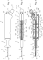
- a fluid injection catheter 1 comprises a conduit 2 connected to a housing 11 comprising a connector 5.
- the inner sheath 3 is for example made of PEBA, and the outer sheath 4 is for example made of Teflon.
- a tip ring 9 is here fixed to a distal end of the outer sheath 4 and is able to slide on at least part of the injection nozzle 7.
- the tip ring 9 is for example made of ceramic. It also has a head 90 of rounded distal shape, as illustrated by Figures 11a and 11b .
- the catheter 1 comprises two assemblies capable of sliding relative to each other.
- a first assembly called here “fixed assembly” comprises the nozzle 7, the inner sheath 3, a tube 17, the connector 5, a plug protector 18 and the electrical plug 14, and the box 11.
- a second assembly here called “mobile assembly” comprises the end ring 9, the outer sheath 4, the sleeve 8, an intermediate element 15, and a ring 16.
- the nozzle 7 is pushed into the inner sheath 3. It is for example glued to the inside of the inner sheath 3 at its distal end.
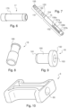
- the nozzle 7 here has a connecting zone 70 promoting an attachment between the nozzle 7 and the inner sheath 3.
- the connecting zone 70 also has grooves 71 and a flat 72.
- the grooves 71 can, for example, serve as a spillway for glue if the assembly is carried out by gluing, in order to prevent glue from overflowing, which also results in a sloppy and unsightly finish.
- the grooves 71 also allow better grip between the nozzle 7 and the inner sheath 3, while the flat 72 serves as a foolproof device for inserting the nozzle 7 into the inner sheath 3 and/or as a reference if it is preferable to insert the nozzle 7 in a certain orientation.
- the flat 72 also makes it easier to insert the nozzle 7 into the inner sheath 3 since it induces a reduction in section. According to another embodiment not shown, however, there could only be one groove 71.
- the nozzle 7 furthermore has here a useful zone 73, outside the inner sheath 3 when they are assembled together.
- the useful zone 73 has a distal end 74a having an outlet orifice 75 through which the fluid is injected into or under a tissue if necessary.
- the distal end 74a is optionally sharp or cutting, or for example beveled (not shown here).
- the useful zone 73 has a narrowed section compared to the connecting zone 70. This makes it possible to create a shoulder 76 acting for example as a stop for the tip ring 9 when the latter is in the pulled position, uncovering the nozzle 7, as shown for example in detail A of the Figure 3 A smaller cross-section also allows a smaller hole to be formed in the tissue when the nozzle penetrates a mucosa to inject fluid, and this also allows the nozzle 7 to be introduced more easily into the tissue.
- the catheter 1 is a bi-functional catheter, i.e. the nozzle 7 also acts as an electrode. Therefore, the nozzle 7 is for example made of a conductive material, for example a metal, and is connected by a conductive wire 10, for example metal, running in a channel 30 of the inner sheath 3, to an electrical plug 14 connected to an electrical connection 51 of the connector 5.
- the conductive wire 10 is preferably welded to a proximal end 74b of the nozzle 7.
- the distal end 74a In the case of a nozzle also acting as an electrode, it is for example useful for the distal end 74a to be provided with a ring 78 (shown Figure 14 ). To ensure better positioning of the ring 78, it is then advantageous for the distal end 74a of the nozzle 7 to have a narrowing 77 (shown here in the embodiment of the figure 13 ), forming another shoulder, intended to receive the ring 78. Such a narrowing 77 could also be formed at the distal end 74a of the nozzle 7 of the Figure 12 . The ring 78 can however be fixed to the distal end 74a of the nozzle 7 without such narrowing, for example by gluing, but this configuration then makes its positioning more delicate.
- the ring 78 here has the shape of a circular plate with holes so as to be adjusted to the section of the distal end 74a (i.e. of the useful zone 73 or of the narrowing 77 if it exists).
- the nozzle 7 comprises a channel 79 for conveying a fluid from the inner sheath 3 to the outlet orifice 75.
- the channel 79 has a section which, on average, narrows towards the outlet orifice 75.
- the channel 79 relatively centered in the nozzle 7, here has a section 79a as wide as possible directly connected to the channel 30 of the inner sheath 3, a funnel-shaped section 79b, an intermediate section 79c which is here slightly wider than the funnel-shaped section 79b, and an injection section 79d.
- These different sections are arranged so as to minimize turbulence in the flow of the fluid while maintaining a fluid pressure at the outlet of the outlet orifice 75 with a minimum of loss. It is noted for example that the sections 79a, 79b and 79c are arranged so as to form a nozzle.
- the inner sheath 3 At the other end of the inner sheath 3, at its proximal end, the inner sheath 3 is fixed to the tube 17, detailed Figure 6 .
- the tube 17 is in turn pushed into an output branch 53 of the connector 5.
- the tube 17, of generally cylindrical shape has a groove 170 extending here over a major part of the length of the tube 17.
- the groove 170 makes it possible, for example, to serve as a spillway for glue if the assembly is carried out by gluing, in order to prevent glue from overflowing, which also provides a sloppy and unattractive finish.
- the groove 170 also makes it possible to promote the gripping of the tube 17 in the connector 5, for example assembled by gluing.
- the connector 5 here has an output branch 53. It also has at least one branch 52 serving for a fluid connection, designated “fluid connection 52”, and in the case of a bi-functional catheter, it further has a branch 51 serving for an electrical connection, designated “electrical connection 51”.
- the connector 5 here is a Y-shaped connector, with a fluid connection 52 for the fluid reservoir 6, an electrical connection 51 and an output connection 53 connecting it to the inner sheath 3.
- the connector 5 has a channel 56 allowing the fluid to be conveyed, which is consequently in direct communication with the channel 30 of the inner sheath 3.
- the outlet branch 53 here has a beveled end 54. It also has an inclined shoulder 55 forming a stop for the tube 17.
- the fluid connection 52 here has a threaded end 52a for a Luer-Lock connection for an inlet of pressurized fluid into the channel 56, a section 56a of which, present at the level of the branch 52, is widened towards the inlet of the fluid, for example to limit turbulence in the flow when it arrives in the catheter 1.
- Branch 51 used for the electrical connection receives the electrical plug 14 connected to the conductive wire 10.
- the electrical plug 14 is here protected by the plug protector 18, which is for example blocked by its foot 180 between the branches 51 and 52 of the connector 5 on the one hand, and the housing 11 on the other hand when the entire catheter 1 is assembled.
- the electrical plug 14 is, for its part, for example blocked in position by a thickening 140 taken between the branch 51 and an internal edge 181 of the plug protector 18.
- the channel 56 of the connector 5, the channel 30 of the inner sheath 3, and the channel 79 of the nozzle 7 make it possible to convey the fluid to be injected from a reservoir, such as for example the reservoir 6 of a pulsed jet generator 101, to the outlet orifice 75 of the nozzle 7.
- the conductive wire 10 runs through the channel 30 of the inner sheath 3 and the channel 56 of the connector 5, branching off into the branch 51.
- the second set is considered mobile relative to this first set.
- the tip ring 9 (detailed Figure 11 ) is fixed in a distal end of the outer sheath 4, as shown in detail A of the Figure 3 .
- the end ring 9 also has a groove 91 here promoting a better grip in the outer sheath 4 and also allowing to serve as a spillway for glue if the assembly is carried out by gluing, in order to prevent glue from overflowing, which also provides a sloppy and unsightly finish.
- the tip ring 9 has a rounded distal shape forming a head 90 of the tip ring 9.
- the head 90 of the tip ring 9 is a little wider so as to form continuity with an external surface of the outer sheath 4 when they are assembled.
- the tip ring 9 finally comprises a channel 93 terminated by an orifice 92 formed at a top of the head 90.
- the channel 93 has for example a diameter substantially equal to a diameter of the useful zone 73 of a nozzle 7 to slide on this useful zone 73 while allowing a seal between the nozzle 7 and the tip ring 9 to prevent fluid or other fluid from infiltrating between the inner sheath 3 and the outer sheath 4.
- the tip ring 9 is for example in abutment against a distal end of the inner sheath 3, or even also of the shoulder 76 if it exists, and in the pushed position (“b”) the tip ring 9 is for example in abutment by its head 90 against the ring 78 if the nozzle 7 is provided with it.
- the outer sheath 4 is fixed in the intermediate element 15 by the ring 16, as shown in detail B of the Figure 3 .
- the intermediate element 15 is here a slender element shown schematically on the Figures 2 and 3 , and detailed Figure 7 .
- the outer sheath 4 here passes inside the intermediate element 15, and around a body 160 of the ring 16. So that the ring 16 can be inserted more easily into the outer sheath 4, it has for example a first beveled end 161.
- the ring 16 also makes it possible to form a stop when the mobile assembly is in the pulled position (“a”) by coming to bear for example on a reinforcement 130 of the housing 11.
- the ring 16 advantageously has a head 162 wider than the body 160.
- the head 162 also serves as a stop for the intermediate element 15 when the ring 16, surrounded by the outer sheath 4, is pushed into it.
- the ring 16 has a channel 163 of diameter substantially equal to a diameter of the inner sheath 3 to be able to slide along the inner sheath 3.
- the intermediate element 15 here has a first zone 151 intended to cooperate with the sleeve 8, and a second zone 152 intended to be positioned inside the housing 11.
- the first zone 151 has a flat 150, for example over its entire length, capable of cooperating with a flat 80 of the sleeve 8 to induce, for example, a mandatory mounting direction of the sleeve 8 on the intermediate element 15. This is for example useful if the sleeve 8 has inscriptions, such as for example arrows illustrating the positions “a” and “b” for extending or retracting the nozzle 7.
- the first zone 151 also has grooves 153 to facilitate gripping with the sleeve 8.
- the grooves 153 also serve as a spillway for glue if the assembly is carried out by gluing, in order to prevent glue from overflowing, which also results in a sloppy and unsightly finish.
- the first zone 151 here has a diameter that is generally smaller than a diameter of the second zone 152 so as to form a shoulder 154 that can serve as a stop for inserting the sleeve 8.
- the first zone 151 finally has a transition zone 155 allowing the diameter of the first zone 151 to be gradually reduced relative to a diameter of the outer sheath.
- a flexible sleeve for example made of elastomer, may be present between the intermediate element 15 and the sleeve 8 so that the sleeve 8 is force-fitted, for example on the flexible sleeve slipped onto the intermediate element 15.
- the flexible sleeve may for example extend on either side beyond the first part 151.
- the sleeve 8 is for example in abutment against the housing 11 when the catheter is in the pulled position (“a”).
- the second zone 152 furthermore has here two pairs of impressions 157a, 157a' and 157b, 157b' capable of cooperating with two pads 120, 120' formed in the housing 11.
- the two impressions of a pair are preferably formed so diametrically opposed so that the two studs 120, 120' also allow the intermediate element 15 to be held and guided in the housing 11.
- other configurations can be envisaged which would, for example, only use one imprint at a time.
- the two pairs of indentations 157a, 157a' and 157b, 157b' allow in particular indexing of the pulled position ("a") or pushed position ("b"). Indeed, in the pulled position, the pair 157a, 157a' cooperates with the studs 120, 120', whereas in the pushed position, it is the pair 157b, 157b' which cooperates with the studs 120, 120'.
- the intermediate element 15 is then slightly compressed between the studs 120, 120' which gives the user a slight feeling of resistance until one of the two pairs of indentations is opposite the studs 120, 120'.
- the positioning of the pairs of prints relative to the pads 120, 120' is secured thanks to the various stops presented previously (such as for example between the end ring 9 and the ring 78 on the one hand or the inner sheath 3 on the other hand, or the ring 16 against the reinforcement 130, or even the sleeve 8 against the housing 11) which prevent a user from pulling or pushing more than necessary, which could for example damage the various bonding or assembly of the parts, or even the parts themselves.
- the intermediate element also comprises here a groove 156.
- the groove 156 has for example a length equal to or slightly greater than a gap between the two pairs of impressions 157a, 157a' and 157b, 157b'.
- the groove 156 cooperates here with a finger 121 of the housing 11.
- the cooperation between the groove 156 and the finger 121 not only makes it possible to secure the movements of the mobile assembly to prevent a user from pulling beyond the pulled position or pushing beyond the pushed position, but also to prevent rotation, or even twisting, of the mobile assembly relative to the fixed assembly.
- the finger 121 then has a diameter substantially equal to a width of the channel 156.
- the channel 156 is positioned between the two pads of the same pair and at equal distances between them.
- the finger 121 is here slightly offset relative to the pads 120, 120' as shown in figures 2 And 5 . So, in pulled position (“a”), the pair of impressions 157a, 157a’ cooperates with the studs 120, 120’ while the finger 121 is close, or even in contact to form a stop, with a bottom 156a of the channel 156. In the pushed position (“b”), not shown in detail here, the pair of impressions 157b, 157b’ would cooperate with the studs 120, 120’ while the finger 121 would be close, or even in contact to form a stop, with a bottom 156b of the channel 156.
- the gap between the pair 157a, 157a', and the pair 157b, 157b' is much greater than the length of a part of the useful zone 73 of the nozzle 7 which can be uncovered or retracted. This is notably due to a structural effect (existence of clearances, elasticity of the assembly), as well as to the elastic properties of the different parts and their constituent materials. It is recalled, for example, that the conduit 2 typically measures more than one meter long for a maximum diameter of approximately 2.5 mm, or even less.
- the housing 11 is formed of a male part 12 (represented Figure 5 ) and a female part 13 (represented Figure 4 ).
- the pads 120, 120' are here formed in the male part 12.
- the pads 120 and 120' have however been represented in dotted lines to illustrate their positioning relative to the pairs of impressions 157a, 157a' and 157b, 157b'.
- the housing 11 can be closed by the male part 12, for example by welding or by gluing.
- the housing 11 is, for example, made of plastic, for example by molding.
- the female part 13 has, for example, a rim 13' and the male part 12 has, for example, a rim 12' capable of being attached to the rim 13' in the female part 13.
- the housing 11 further comprises different pairs of assembly pins 122, 132 (in this case six pairs) comprising a male pin 122 in the male part 12 and a female pin 132 in the female part 13 of the housing 11.
- the housing also comprises reinforcements, such as reinforcement 130, cooperating with a reinforcement 123 of the male part.
- the reinforcements 130 and 123 respectively have a groove 134 and 124 intended to receive the inner sheath 3 to hold it in position.
- the grooves 134 and 124 therefore have a curvature substantially equal to a curvature of a cross-section of the inner sheath 3.
- the male part further has a reinforcement 125 provided with a groove 126
- the female part has a reinforcement 135 complementary to the reinforcement 125, provided with a groove 136.
- the grooves 126 and 136 for their part, have a curvature substantially equal to a curvature of a cross-section of the second zone 152 of the intermediate element 15 to hold it in position while allowing it to slide.
- the housing includes cutouts 127 and 137 for the passage of the second zone 152 of the intermediate element 15 to hold it in position while allowing it to slide, cutouts 128, 138 for the passage of the fluid connection 52 of the connector 5, and cutouts 129, 139 for the passage of the electrical connection 51 of the connector 5 surrounded by the plug protector 18.
- FIG. 17 schematically presents a device 100 according to an embodiment of the present invention.
- the device 100 comprises at least one generator 101 and a catheter 1 according to the invention, for example as described previously with reference to figures 1 to 16 .
- the generator 101 is a high-pressure pulsed jet generator designed to generate pulses of fluid under high pressure from at least one fluid contained in a reservoir formed here by a flexible pocket 6, placed in a sealed enclosure 102, pressurized, for example using a bottle 103 containing pressurized gas.
- the enclosure 102 has at least one fluid outlet 104 and one pressurized gas inlet 105.
- the generator 101 comprises a pressurization device for the enclosure 102 which comprises a source of pressurized gas, for example here the bottle 103 located outside the enclosure 102, which supplies a pressurized gas entering the enclosure 102 through the pressurized gas inlet 105 to increase the internal pressure of the enclosure 102.
- a pressure regulating device 106 makes it possible to regulate the pressure inside the enclosure 102.
- the pressure regulating device 106 is arranged at the pressurized gas inlet 105, just upstream, for example outside the enclosure 102.
- the generator 101 further comprises a fluid circuit which comprises the pocket 6 which has an outlet for the fluid which it contains, a junction connector 107, and a connection conduit 108 itself connected to the pocket 6 by the junction connector 107.
- the junction connector 107, the connection conduit 108 as well as the pocket 6 are arranged in the enclosure 102.
- the fluid circuit further comprises a hydraulic sequencer 109 connected at the inlet to at least the connection conduit 108, and at the outlet to an outlet conduit 110 connected to the fluid outlet 104 of the enclosure 102.
- the outlet conduit 110 is in turn connected to an external connecting conduit 112 with the catheter 1.
- the fluid outlet 104 is preferably provided with a cone fitting 111 for example, a tapered portion of which is preferably directed towards the outside of the enclosure 102 so that the internal pressure of the enclosure 102 tends to push the cone in when the pressure increases.
- the hydraulic sequencer 109 with its associated control means are advantageously included in a replaceable and interchangeable cassette, here placed inside the enclosure 102.
- the generator 101 is capable of generating a pulse of fluid at a pressure of between 2 and 30 bars, and of a volume of fluid per pulse of between 100 ⁇ L and 10 mL. For this, it is then preferable for the flexible deformable envelope to have a corresponding volume.
- the catheter 1 is thus connected on the one hand to the high-pressure jet generator 101 by the fluid connection 52 of the connector 5.
- the device 100 further comprises an electrical generator 200 to which the catheter 1 is then connected on the other hand, for example by a cable 201 connected to the electrical connection 51 of the connector 5.
- the electrical generator 200 is generally designated by the term “ESU”.
Landscapes
- Health & Medical Sciences (AREA)
- Life Sciences & Earth Sciences (AREA)
- Surgery (AREA)
- Engineering & Computer Science (AREA)
- General Health & Medical Sciences (AREA)
- Animal Behavior & Ethology (AREA)
- Public Health (AREA)
- Veterinary Medicine (AREA)
- Biomedical Technology (AREA)
- Heart & Thoracic Surgery (AREA)
- Nuclear Medicine, Radiotherapy & Molecular Imaging (AREA)
- Medical Informatics (AREA)
- Molecular Biology (AREA)
- Otolaryngology (AREA)
- Plasma & Fusion (AREA)
- Physics & Mathematics (AREA)
- Cardiology (AREA)
- Biophysics (AREA)
- Pulmonology (AREA)
- Anesthesiology (AREA)
- Hematology (AREA)
- Vascular Medicine (AREA)
- Media Introduction/Drainage Providing Device (AREA)
- Infusion, Injection, And Reservoir Apparatuses (AREA)
- Surgical Instruments (AREA)
- Materials For Medical Uses (AREA)
Claims (14)
- Bi-funktionaler Katheter (1) mit:• einem Kanal (2)• einem Verbinder (5), der eine Fluidverbindung (52) und eine elektrische Verbindung (51) aufweist,• einer inneren Hülle (3), die den Kanal (2) bildet, der es erlaubt, den Katheter (1) mit einem Fluidspeicher zu verbinden,• einer Einspritzdüse (7), die an einem distalen Ende der inneren Hülle (3) befestigt ist, wobei die Einspritzdüse (7) eine Elektrode bildet,• und einer äußeren Hülle (4), die die innere Hülle (3) umgibt, wobei eine der inneren Hülle (3) und der äußeren Hülle (4) relativ zur anderen der inneren Hülle (3) und der äußeren Hülle (4) beweglich ist,dadurch gekennzeichnet, dass die Elektrode mit der elektrischen Verbindung (51) verbunden ist und ein distales Ende (74a) der Elektrode einen Ring (78) mit einer flachen distalen Fläche aufweist.
- Katheter (1) nach Anspruch 1, dadurch gekennzeichnet, dass die innere Hülle (3) aus PEBA ist.
- Katheter (1) nach einem der Ansprüche 1 oder 2, dadurch gekennzeichnet, dass die äußere Hülle (4) aus Teflon ist.
- Katheter (1) nach einem der Ansprüche 1 bis 3, dadurch gekennzeichnet, dass er einen Spritzenring (9) aufweist, der an einem distalen Ende der äußeren Hülle (4) befestigt ist, die zumindest in einen Teil der Einspritzdüse (7) gleiten kann.
- Katheter (1) nach Anspruch 4, dadurch gekennzeichnet, dass der Spritzenring (9) aus Keramik ist und einen Kopf (90) aufweist, dessen distale Form abgerundet ist.
- Katheter (1) nach einem der Ansprüche 1 bis 5, dadurch gekennzeichnet, dass der Ring (78) eine Form einer kreisförmigen Platte aufweist, die so durchlöchert ist, dass sie an den Abschnitt des distalen Endes (74a) angepasst ist.
- Katheter (1) nach einem der Ansprüche 1 bis 6, dadurch gekennzeichnet, dass das distale Ende (74a) der Düse (7) eine Verengung (77) aufweist, die eine Schulter bildet, die zur Aufnahme des Rings (78) bestimmt ist.
- Katheter (1) nach einem der Ansprüche 1 bis 7, dadurch gekennzeichnet, dass die Düse (7) einen Kanal (79) aufweist, der es erlaubt, ein Fluid von der inneren Hülle (3) zu einer Ausgangsöffnung (75) zu leiten.
- Katheter (1) nach einem der Ansprüche 1 bis 8, dadurch gekennzeichnet, dass die Elektrode (7) mit der elektrischen Verbindung (51) durch einen leitenden Draht (10) verbunden ist, der in der inneren Hülle (3) verläuft.
- Katheter (1) nach einem der Ansprüche 1 bis 9, dadurch gekennzeichnet, dass die äußere Hülle (4) an einer Hülse (8) befestigt ist, wobei die Hülse (8) und die äußere Hülle (4) gegenüber der inneren Hülle (3) gleiten und mindestens eine gedrückte Position ("b"), in der die äußere Hülle (4) zumindest einen Teil der Einspritzdüse (7) bedeckt, und eine gezogene Position ("a"), in der die äußere Hülle (4) den Teil der Einspritzdüse (7) abdeckt, einnehmen.
- Vorrichtung (100) mit einem Generator (101) von gepulsten Jets, die einen Behälter (6) und einen Katheter (1) aufweist, dadurch gekennzeichnet, dass der Katheter (1) ein Katheter (1) nach einem der Ansprüche 1 bis 10 ist, der zum einen mit dem Generator (101) von gepulsten Jets durch eine Fluidverbindung (52) des Verbinders (5) verbunden ist, und dadurch, dass der Katheter (1) weiterhin andererseits mit einem elektrischen Generator (200) durch eine elektrische Verbindung (51) des Verbinders (5) verbunden ist.
- Vorrichtung (100) nach Anspruch 11, dadurch gekennzeichnet, dass der Generator (101) für gepulste Jets ein Generator (101) für gepulste Jets hohen Drucks ist, der zum Erzeugen von Fluidpulsen unter hohem Druck aus mindestens einem Fluid vorgesehen ist, das in einer flexiblen Tasche (6) enthalten ist, die den Behälter bildet, der in einem dichten Gehäuse (102) angeordnet ist, das unter Druck gesetzt ist, wobei das Gehäuse (102) mindestens einen Fluidausgang (104) aufweist, wobei der Generator (101) aufweist:• eine Vorrichtung zum Unter-Druck-Setzen des Gehäuses, die eine Quelle (103) für unter Druck stehendes Gas aufweist, die ein unter Druck stehendes Gas liefert, das in das Gehäuse (102) zum Erhöhen von dessen internen Druck eindringt,• eine Vorrichtung (106) zur Einstellung des Drucks, die den Druck im Inneren des Gehäuses (102) regelt,• zumindest einen Verbinder (107) zum Verbinden einer weichen Tasche (6) mit einem Anschlusskanal (108), wobei der Verbinder (107) und der Anschlusskanal (108) in dem Gehäuse (102) angeordnet sind,• einen hydraulischen Sequenzer (109), der zumindest aufweist:- einen Eingang, in den zumindest der Anschlusskanal (108) gelangt, und einen Ausgang mit dem ein Ausgangskanal (110) verbunden ist, der hydraulisch mit dem Äußeren des Generators zusammenwirkt,- eine flexibel verformbare Hülle in einer hydraulischen Verbindung, wobei all das dem Druck in der Kammer (102) ausgesetzt ist, Ausgangskanal zur Verbindung- mindestens eine hydraulische Absperrung in der hydraulischen Verbindung,- eine Einrichtung zum Betätigen der hydraulischen Absperrung,• und den dichten Ausgangskanal (110) zwischen dem Ausgang des Sequenzers (109) und dem Ausgang (104) des Gehäuses (102), verbunden mit einem äußeren Verbindungskanal (112) mit dem Katheter (1).
- Vorrichtung (100) nach einem der Ansprüche 11 oder 12, dadurch gekennzeichnet, dass der Generator (101) ein Ein-Aus-Magnetventil aufweist, das in dem unter Druck stehenden Gehäuse angeordnet ist, das einen Fluidpuls mit einem Druck zwischen 2 und 30 Bar erzeugt.
- Vorrichtung (100) nach einem der Ansprüche 11 bis 13, dadurch gekennzeichnet, dass die weiche, flexible Hülle ein Fluidvolumen pro Puls zwischen 100 µL und10 mL darstellt.
Priority Applications (1)
| Application Number | Priority Date | Filing Date | Title |
|---|---|---|---|
| EP25163165.1A EP4559419A3 (de) | 2013-04-04 | 2014-04-01 | Bifunktioneller katheter mit zwei schiebeschläuchen |
Applications Claiming Priority (3)
| Application Number | Priority Date | Filing Date | Title |
|---|---|---|---|
| FR1353033A FR3004115B1 (fr) | 2013-04-04 | 2013-04-04 | Catheter d'injection de fluide a deux gaines coulissantes |
| EP14722250.9A EP2981321B1 (de) | 2013-04-04 | 2014-04-01 | Doppelfunktionskatheter mit zwei verschiebbaren schleusen |
| PCT/FR2014/050776 WO2014162093A1 (fr) | 2013-04-04 | 2014-04-01 | Catheter bi-fonctionnel a deux gaines coulissantes |
Related Parent Applications (1)
| Application Number | Title | Priority Date | Filing Date |
|---|---|---|---|
| EP14722250.9A Division EP2981321B1 (de) | 2013-04-04 | 2014-04-01 | Doppelfunktionskatheter mit zwei verschiebbaren schleusen |
Related Child Applications (2)
| Application Number | Title | Priority Date | Filing Date |
|---|---|---|---|
| EP25163165.1A Division-Into EP4559419A3 (de) | 2013-04-04 | 2014-04-01 | Bifunktioneller katheter mit zwei schiebeschläuchen |
| EP25163165.1A Division EP4559419A3 (de) | 2013-04-04 | 2014-04-01 | Bifunktioneller katheter mit zwei schiebeschläuchen |
Publications (2)
| Publication Number | Publication Date |
|---|---|
| EP3906960A1 EP3906960A1 (de) | 2021-11-10 |
| EP3906960B1 true EP3906960B1 (de) | 2025-05-28 |
Family
ID=48795689
Family Applications (3)
| Application Number | Title | Priority Date | Filing Date |
|---|---|---|---|
| EP14722250.9A Active EP2981321B1 (de) | 2013-04-04 | 2014-04-01 | Doppelfunktionskatheter mit zwei verschiebbaren schleusen |
| EP21175191.2A Active EP3906960B1 (de) | 2013-04-04 | 2014-04-01 | Bifunktionaler katheter mit zwei schiebehüllen |
| EP25163165.1A Pending EP4559419A3 (de) | 2013-04-04 | 2014-04-01 | Bifunktioneller katheter mit zwei schiebeschläuchen |
Family Applications Before (1)
| Application Number | Title | Priority Date | Filing Date |
|---|---|---|---|
| EP14722250.9A Active EP2981321B1 (de) | 2013-04-04 | 2014-04-01 | Doppelfunktionskatheter mit zwei verschiebbaren schleusen |
Family Applications After (1)
| Application Number | Title | Priority Date | Filing Date |
|---|---|---|---|
| EP25163165.1A Pending EP4559419A3 (de) | 2013-04-04 | 2014-04-01 | Bifunktioneller katheter mit zwei schiebeschläuchen |
Country Status (9)
| Country | Link |
|---|---|
| EP (3) | EP2981321B1 (de) |
| JP (5) | JP6567497B2 (de) |
| CN (2) | CN110403693B (de) |
| AU (1) | AU2014246931B2 (de) |
| CA (1) | CA2908251C (de) |
| ES (1) | ES2876425T3 (de) |
| FR (1) | FR3004115B1 (de) |
| PL (1) | PL2981321T3 (de) |
| WO (1) | WO2014162093A1 (de) |
Families Citing this family (7)
| Publication number | Priority date | Publication date | Assignee | Title |
|---|---|---|---|---|
| CN106583848A (zh) * | 2016-12-16 | 2017-04-26 | 青岛海之源智能技术有限公司 | 一种应用电流变效应的固态水刀切割装置 |
| US11039850B2 (en) | 2018-02-28 | 2021-06-22 | Gi Supply | Endoscopic tool with suction for facilitating injection of a fluid into a submucosal layer of tissue |
| BR112022009156A2 (pt) * | 2019-11-13 | 2022-07-26 | Haldor Topsoe As | Sistema de lavagem para remoção de haletos a partir de uma corrente de hidrocarbonetos |
| EP4117745A4 (de) * | 2020-03-11 | 2024-01-24 | Medality Medical LLC | Vorrichtungen zur entfernung von viszeralfett sowie zugehörige systeme und verfahren |
| EP4260827A4 (de) | 2021-03-12 | 2024-11-20 | Hoya Corporation | Endoskopisches behandlungsgerät |
| CN113577504A (zh) * | 2021-07-13 | 2021-11-02 | 宁波迪创医疗科技有限公司 | 一种心衰治疗系统 |
| CN117379169A (zh) * | 2023-12-04 | 2024-01-12 | 南京亿高医疗科技股份有限公司 | 氩气消融导管及氩气直喷侧喷的切换方法 |
Family Cites Families (25)
| Publication number | Priority date | Publication date | Assignee | Title |
|---|---|---|---|---|
| JP3115902B2 (ja) * | 1991-03-22 | 2000-12-11 | オリンパス光学工業株式会社 | 外科手術用ハンドピ−ス |
| US6156029A (en) * | 1997-11-25 | 2000-12-05 | Eclipse Surgical Technologies, Inc. | Selective treatment of endocardial/myocardial boundary |
| US6344027B1 (en) * | 1999-12-08 | 2002-02-05 | Scimed Life Systems, Inc. | Needle-less injection apparatus and method |
| FR2830455B1 (fr) * | 2001-10-09 | 2004-06-25 | Saphir Medical | Catheter a outil d'extremite perforant ou piquant retractable |
| US7285116B2 (en) * | 2004-05-15 | 2007-10-23 | Irvine Biomedical Inc. | Non-contact tissue ablation device and methods thereof |
| EP1458437B1 (de) * | 2001-12-26 | 2010-03-03 | Yale University | Gefäss-shuntvorrichtung |
| AU2004206911B2 (en) * | 2003-01-15 | 2009-07-16 | Adagio Medical, Inc. | Cryotherapy probe and system |
| JP4698128B2 (ja) * | 2003-03-28 | 2011-06-08 | テルモ株式会社 | 穿刺センサを有するカテーテル |
| US7678077B2 (en) * | 2004-02-20 | 2010-03-16 | Boston Scientific Scimed, Inc. | Variable depth injection device and method |
| JP4373890B2 (ja) * | 2004-10-20 | 2009-11-25 | Hoya株式会社 | 内視鏡用高周波処置具 |
| GB0526151D0 (en) * | 2005-12-22 | 2006-02-01 | Eschmann Holdings Ltd | Improvements in or relating to surgical instruments |
| US9232959B2 (en) * | 2007-01-02 | 2016-01-12 | Aquabeam, Llc | Multi fluid tissue resection methods and devices |
| JP5111931B2 (ja) * | 2007-05-07 | 2013-01-09 | オリンパスメディカルシステムズ株式会社 | 内視鏡用処置具 |
| EP2219536B1 (de) * | 2007-10-23 | 2012-12-19 | Boston Scientific Scimed, Inc. | Gerät zur behandlung von gewebe |
| DE102008025233A1 (de) * | 2008-05-27 | 2009-12-03 | Erbe Elektromedizin Gmbh | Wasserstrahlchirurgieinstrument |
| AU2009235053B2 (en) * | 2008-04-08 | 2014-05-08 | Jetprep Ltd. | Body passage cleansing device |
| US9333287B2 (en) * | 2008-04-08 | 2016-05-10 | Jet Prep Ltd. | Body passage cleansing device |
| JP5415727B2 (ja) * | 2008-08-13 | 2014-02-12 | オリンパスメディカルシステムズ株式会社 | 内視鏡用処置具 |
| DE202009018056U1 (de) * | 2009-04-16 | 2010-12-30 | Erbe Elektromedizin Gmbh | Endoskopisches Chirurgieinstrument |
| WO2010150697A1 (ja) * | 2009-06-23 | 2010-12-29 | オリンパスメディカルシステムズ株式会社 | 医療システム |
| CN102548495B (zh) * | 2009-08-14 | 2015-08-05 | 波士顿科学西美德公司 | 用于制造和使用具有带有改善的锚定能力的标测导管的医学消融系统的系统和方法 |
| FR2960415B1 (fr) * | 2010-05-27 | 2012-12-28 | Nestis | Generateur de jets pulses haute pression d'un liquide en vue d'applications medicales et chirugicales |
| FR2971414A1 (fr) * | 2011-02-10 | 2012-08-17 | Chru Lille | Dispositif d'irradiation lumineuse pour l'application d'un faisceau lumineux sur ou dans un corps, notamment un corps humain |
| US9439707B2 (en) * | 2011-03-25 | 2016-09-13 | Medtronic Cryocath Lp | Spray nozzle design for a catheter |
| US10743932B2 (en) * | 2011-07-28 | 2020-08-18 | Biosense Webster (Israel) Ltd. | Integrated ablation system using catheter with multiple irrigation lumens |
-
2013
- 2013-04-04 FR FR1353033A patent/FR3004115B1/fr not_active Expired - Fee Related
-
2014
- 2014-04-01 WO PCT/FR2014/050776 patent/WO2014162093A1/fr not_active Ceased
- 2014-04-01 EP EP14722250.9A patent/EP2981321B1/de active Active
- 2014-04-01 PL PL14722250T patent/PL2981321T3/pl unknown
- 2014-04-01 JP JP2016505878A patent/JP6567497B2/ja active Active
- 2014-04-01 ES ES14722250T patent/ES2876425T3/es active Active
- 2014-04-01 CA CA2908251A patent/CA2908251C/en active Active
- 2014-04-01 EP EP21175191.2A patent/EP3906960B1/de active Active
- 2014-04-01 CN CN201910682728.XA patent/CN110403693B/zh active Active
- 2014-04-01 EP EP25163165.1A patent/EP4559419A3/de active Pending
- 2014-04-01 AU AU2014246931A patent/AU2014246931B2/en not_active Ceased
- 2014-04-01 CN CN201480026718.6A patent/CN105358205B/zh active Active
-
2019
- 2019-07-31 JP JP2019140806A patent/JP7277307B2/ja active Active
-
2022
- 2022-01-26 JP JP2022010029A patent/JP7427696B6/ja active Active
-
2023
- 2023-10-17 JP JP2023179018A patent/JP7622181B2/ja active Active
-
2025
- 2025-01-15 JP JP2025005231A patent/JP2025061293A/ja active Pending
Also Published As
| Publication number | Publication date |
|---|---|
| JP2019213883A (ja) | 2019-12-19 |
| JP2016514560A (ja) | 2016-05-23 |
| JP2025061293A (ja) | 2025-04-10 |
| JP7277307B2 (ja) | 2023-05-18 |
| FR3004115B1 (fr) | 2016-05-06 |
| FR3004115A1 (fr) | 2014-10-10 |
| JP2022058757A (ja) | 2022-04-12 |
| JP7622181B2 (ja) | 2025-01-27 |
| JP7427696B6 (ja) | 2024-03-18 |
| EP2981321A1 (de) | 2016-02-10 |
| CN110403693A (zh) | 2019-11-05 |
| WO2014162093A1 (fr) | 2014-10-09 |
| ES2876425T3 (es) | 2021-11-12 |
| PL2981321T3 (pl) | 2021-10-04 |
| EP4559419A3 (de) | 2025-08-20 |
| CA2908251A1 (en) | 2014-10-09 |
| AU2014246931B2 (en) | 2019-02-14 |
| EP3906960A1 (de) | 2021-11-10 |
| JP6567497B2 (ja) | 2019-08-28 |
| CN105358205B (zh) | 2019-08-20 |
| CA2908251C (en) | 2024-01-23 |
| CN105358205A (zh) | 2016-02-24 |
| JP7427696B2 (ja) | 2024-02-05 |
| JP2023179723A (ja) | 2023-12-19 |
| AU2014246931A1 (en) | 2015-11-12 |
| EP4559419A2 (de) | 2025-05-28 |
| CN110403693B (zh) | 2022-09-09 |
| EP2981321B1 (de) | 2021-05-26 |
Similar Documents
| Publication | Publication Date | Title |
|---|---|---|
| EP3906960B1 (de) | Bifunktionaler katheter mit zwei schiebehüllen | |
| EP1027091B1 (de) | Universalkatheter | |
| EP2170448B1 (de) | Vorrichtung zur einführung eines katheterführungsdrahts in ein gefäss | |
| EP0091895B1 (de) | Durch die Harnröhre einzuführende Vorrichtung zur Drainage der Harnblase durch die Bauchdecke | |
| WO2009090333A1 (fr) | Dispositif de gonflage d'un implant chirurgical | |
| WO1993019790A1 (fr) | Canule | |
| EP0852153B1 (de) | Vorrichtung zum Wechseln eines Beatmungstubus in der Trachea eines Patienten | |
| EP2421486A1 (de) | Chirurgisches band mit fertiger konstruktion | |
| CA3097085A1 (fr) | Catheter, ballon gonflable pour cathether | |
| EP2032200A1 (de) | Adapter für ein einführungsventil in einem menschlichen oder tierischen körper | |
| EP3630252A1 (de) | Orientierbarer katheter, vorrichtung und verfahren für chirurgischen eingriff | |
| EP0360717B1 (de) | Katheter, der beim Anschluss drehbar ist | |
| EP3787727A1 (de) | Katheter, medizinische vorrichtung zum einführen einer behandlungslösung | |
| FR3018183A1 (fr) | Dispositif pour realiser une derivation sur un vaisseau sanguin | |
| CA2116696A1 (fr) | Sonde endotracheale |
Legal Events
| Date | Code | Title | Description |
|---|---|---|---|
| PUAI | Public reference made under article 153(3) epc to a published international application that has entered the european phase |
Free format text: ORIGINAL CODE: 0009012 |
|
| STAA | Information on the status of an ep patent application or granted ep patent |
Free format text: STATUS: REQUEST FOR EXAMINATION WAS MADE |
|
| 17P | Request for examination filed |
Effective date: 20210613 |
|
| AC | Divisional application: reference to earlier application |
Ref document number: 2981321 Country of ref document: EP Kind code of ref document: P |
|
| AK | Designated contracting states |
Kind code of ref document: A1 Designated state(s): AL AT BE BG CH CY CZ DE DK EE ES FI FR GB GR HR HU IE IS IT LI LT LU LV MC MK MT NL NO PL PT RO RS SE SI SK SM TR |
|
| B565 | Issuance of search results under rule 164(2) epc |
Effective date: 20211008 |
|
| RAP1 | Party data changed (applicant data changed or rights of an application transferred) |
Owner name: BOSTON SCIENTIFIC MEDICAL DEVICE LIMITED |
|
| GRAP | Despatch of communication of intention to grant a patent |
Free format text: ORIGINAL CODE: EPIDOSNIGR1 |
|
| STAA | Information on the status of an ep patent application or granted ep patent |
Free format text: STATUS: GRANT OF PATENT IS INTENDED |
|
| RIC1 | Information provided on ipc code assigned before grant |
Ipc: A61B 17/00 20060101ALN20241203BHEP Ipc: A61B 18/00 20060101ALN20241203BHEP Ipc: A61B 18/14 20060101ALI20241203BHEP Ipc: A61B 17/3203 20060101ALI20241203BHEP Ipc: A61M 25/00 20060101AFI20241203BHEP |
|
| INTG | Intention to grant announced |
Effective date: 20241216 |
|
| GRAS | Grant fee paid |
Free format text: ORIGINAL CODE: EPIDOSNIGR3 |
|
| GRAA | (expected) grant |
Free format text: ORIGINAL CODE: 0009210 |
|
| STAA | Information on the status of an ep patent application or granted ep patent |
Free format text: STATUS: THE PATENT HAS BEEN GRANTED |
|
| AC | Divisional application: reference to earlier application |
Ref document number: 2981321 Country of ref document: EP Kind code of ref document: P |
|
| AK | Designated contracting states |
Kind code of ref document: B1 Designated state(s): AL AT BE BG CH CY CZ DE DK EE ES FI FR GB GR HR HU IE IS IT LI LT LU LV MC MK MT NL NO PL PT RO RS SE SI SK SM TR |
|
| REG | Reference to a national code |
Ref country code: GB Ref legal event code: FG4D Free format text: NOT ENGLISH |
|
| REG | Reference to a national code |
Ref country code: CH Ref legal event code: EP |
|
| REG | Reference to a national code |
Ref country code: IE Ref legal event code: FG4D Free format text: LANGUAGE OF EP DOCUMENT: FRENCH Ref country code: DE Ref legal event code: R096 Ref document number: 602014091995 Country of ref document: DE |
|
| REG | Reference to a national code |
Ref country code: NL Ref legal event code: FP |
|
| PG25 | Lapsed in a contracting state [announced via postgrant information from national office to epo] |
Ref country code: FI Free format text: LAPSE BECAUSE OF FAILURE TO SUBMIT A TRANSLATION OF THE DESCRIPTION OR TO PAY THE FEE WITHIN THE PRESCRIBED TIME-LIMIT Effective date: 20250528 Ref country code: ES Free format text: LAPSE BECAUSE OF FAILURE TO SUBMIT A TRANSLATION OF THE DESCRIPTION OR TO PAY THE FEE WITHIN THE PRESCRIBED TIME-LIMIT Effective date: 20250528 |
|
| REG | Reference to a national code |
Ref country code: LT Ref legal event code: MG9D |
|
| PG25 | Lapsed in a contracting state [announced via postgrant information from national office to epo] |
Ref country code: NO Free format text: LAPSE BECAUSE OF FAILURE TO SUBMIT A TRANSLATION OF THE DESCRIPTION OR TO PAY THE FEE WITHIN THE PRESCRIBED TIME-LIMIT Effective date: 20250828 Ref country code: GR Free format text: LAPSE BECAUSE OF FAILURE TO SUBMIT A TRANSLATION OF THE DESCRIPTION OR TO PAY THE FEE WITHIN THE PRESCRIBED TIME-LIMIT Effective date: 20250829 |
|
| PG25 | Lapsed in a contracting state [announced via postgrant information from national office to epo] |
Ref country code: PL Free format text: LAPSE BECAUSE OF FAILURE TO SUBMIT A TRANSLATION OF THE DESCRIPTION OR TO PAY THE FEE WITHIN THE PRESCRIBED TIME-LIMIT Effective date: 20250528 |
|
| PG25 | Lapsed in a contracting state [announced via postgrant information from national office to epo] |
Ref country code: BG Free format text: LAPSE BECAUSE OF FAILURE TO SUBMIT A TRANSLATION OF THE DESCRIPTION OR TO PAY THE FEE WITHIN THE PRESCRIBED TIME-LIMIT Effective date: 20250528 |
|
| PG25 | Lapsed in a contracting state [announced via postgrant information from national office to epo] |
Ref country code: HR Free format text: LAPSE BECAUSE OF FAILURE TO SUBMIT A TRANSLATION OF THE DESCRIPTION OR TO PAY THE FEE WITHIN THE PRESCRIBED TIME-LIMIT Effective date: 20250528 |
|
| PG25 | Lapsed in a contracting state [announced via postgrant information from national office to epo] |
Ref country code: RS Free format text: LAPSE BECAUSE OF FAILURE TO SUBMIT A TRANSLATION OF THE DESCRIPTION OR TO PAY THE FEE WITHIN THE PRESCRIBED TIME-LIMIT Effective date: 20250828 |
|
| PG25 | Lapsed in a contracting state [announced via postgrant information from national office to epo] |
Ref country code: IS Free format text: LAPSE BECAUSE OF FAILURE TO SUBMIT A TRANSLATION OF THE DESCRIPTION OR TO PAY THE FEE WITHIN THE PRESCRIBED TIME-LIMIT Effective date: 20250928 |
|
| PG25 | Lapsed in a contracting state [announced via postgrant information from national office to epo] |
Ref country code: LV Free format text: LAPSE BECAUSE OF FAILURE TO SUBMIT A TRANSLATION OF THE DESCRIPTION OR TO PAY THE FEE WITHIN THE PRESCRIBED TIME-LIMIT Effective date: 20250528 |
|
| REG | Reference to a national code |
Ref country code: AT Ref legal event code: MK05 Ref document number: 1798289 Country of ref document: AT Kind code of ref document: T Effective date: 20250528 |
|
| PG25 | Lapsed in a contracting state [announced via postgrant information from national office to epo] |
Ref country code: SM Free format text: LAPSE BECAUSE OF FAILURE TO SUBMIT A TRANSLATION OF THE DESCRIPTION OR TO PAY THE FEE WITHIN THE PRESCRIBED TIME-LIMIT Effective date: 20250528 Ref country code: AT Free format text: LAPSE BECAUSE OF FAILURE TO SUBMIT A TRANSLATION OF THE DESCRIPTION OR TO PAY THE FEE WITHIN THE PRESCRIBED TIME-LIMIT Effective date: 20250528 Ref country code: DK Free format text: LAPSE BECAUSE OF FAILURE TO SUBMIT A TRANSLATION OF THE DESCRIPTION OR TO PAY THE FEE WITHIN THE PRESCRIBED TIME-LIMIT Effective date: 20250528 |
|
| PG25 | Lapsed in a contracting state [announced via postgrant information from national office to epo] |
Ref country code: CZ Free format text: LAPSE BECAUSE OF FAILURE TO SUBMIT A TRANSLATION OF THE DESCRIPTION OR TO PAY THE FEE WITHIN THE PRESCRIBED TIME-LIMIT Effective date: 20250528 |
|
| PG25 | Lapsed in a contracting state [announced via postgrant information from national office to epo] |
Ref country code: EE Free format text: LAPSE BECAUSE OF FAILURE TO SUBMIT A TRANSLATION OF THE DESCRIPTION OR TO PAY THE FEE WITHIN THE PRESCRIBED TIME-LIMIT Effective date: 20250528 |
|
| PG25 | Lapsed in a contracting state [announced via postgrant information from national office to epo] |
Ref country code: SK Free format text: LAPSE BECAUSE OF FAILURE TO SUBMIT A TRANSLATION OF THE DESCRIPTION OR TO PAY THE FEE WITHIN THE PRESCRIBED TIME-LIMIT Effective date: 20250528 |
|
| PG25 | Lapsed in a contracting state [announced via postgrant information from national office to epo] |
Ref country code: IT Free format text: LAPSE BECAUSE OF FAILURE TO SUBMIT A TRANSLATION OF THE DESCRIPTION OR TO PAY THE FEE WITHIN THE PRESCRIBED TIME-LIMIT Effective date: 20250528 |
|
| REG | Reference to a national code |
Ref country code: DE Ref legal event code: R097 Ref document number: 602014091995 Country of ref document: DE |
|
| PLBE | No opposition filed within time limit |
Free format text: ORIGINAL CODE: 0009261 |
|
| STAA | Information on the status of an ep patent application or granted ep patent |
Free format text: STATUS: NO OPPOSITION FILED WITHIN TIME LIMIT |
|
| PGFP | Annual fee paid to national office [announced via postgrant information from national office to epo] |
Ref country code: GB Payment date: 20260319 Year of fee payment: 13 |
|
| REG | Reference to a national code |
Ref country code: CH Ref legal event code: L10 Free format text: ST27 STATUS EVENT CODE: U-0-0-L10-L00 (AS PROVIDED BY THE NATIONAL OFFICE) Effective date: 20260409 |
|
| PGFP | Annual fee paid to national office [announced via postgrant information from national office to epo] |
Ref country code: IE Payment date: 20260320 Year of fee payment: 13 |
|
| PGFP | Annual fee paid to national office [announced via postgrant information from national office to epo] |
Ref country code: NL Payment date: 20260319 Year of fee payment: 13 |