EP3905367B1 - Battery box and battery module - Google Patents
Battery box and battery module Download PDFInfo
- Publication number
- EP3905367B1 EP3905367B1 EP19902042.1A EP19902042A EP3905367B1 EP 3905367 B1 EP3905367 B1 EP 3905367B1 EP 19902042 A EP19902042 A EP 19902042A EP 3905367 B1 EP3905367 B1 EP 3905367B1
- Authority
- EP
- European Patent Office
- Prior art keywords
- battery
- welding
- end plate
- battery box
- side plate
- Prior art date
- Legal status (The legal status is an assumption and is not a legal conclusion. Google has not performed a legal analysis and makes no representation as to the accuracy of the status listed.)
- Active
Links
Images

Classifications
-
- H—ELECTRICITY
- H01—ELECTRIC ELEMENTS
- H01M—PROCESSES OR MEANS, e.g. BATTERIES, FOR THE DIRECT CONVERSION OF CHEMICAL ENERGY INTO ELECTRICAL ENERGY
- H01M50/00—Constructional details or processes of manufacture of the non-active parts of electrochemical cells other than fuel cells, e.g. hybrid cells
- H01M50/20—Mountings; Secondary casings or frames; Racks, modules or packs; Suspension devices; Shock absorbers; Transport or carrying devices; Holders
- H01M50/244—Secondary casings; Racks; Suspension devices; Carrying devices; Holders characterised by their mounting method
-
- H—ELECTRICITY
- H01—ELECTRIC ELEMENTS
- H01M—PROCESSES OR MEANS, e.g. BATTERIES, FOR THE DIRECT CONVERSION OF CHEMICAL ENERGY INTO ELECTRICAL ENERGY
- H01M50/00—Constructional details or processes of manufacture of the non-active parts of electrochemical cells other than fuel cells, e.g. hybrid cells
- H01M50/20—Mountings; Secondary casings or frames; Racks, modules or packs; Suspension devices; Shock absorbers; Transport or carrying devices; Holders
- H01M50/204—Racks, modules or packs for multiple batteries or multiple cells
-
- H—ELECTRICITY
- H01—ELECTRIC ELEMENTS
- H01M—PROCESSES OR MEANS, e.g. BATTERIES, FOR THE DIRECT CONVERSION OF CHEMICAL ENERGY INTO ELECTRICAL ENERGY
- H01M50/00—Constructional details or processes of manufacture of the non-active parts of electrochemical cells other than fuel cells, e.g. hybrid cells
- H01M50/20—Mountings; Secondary casings or frames; Racks, modules or packs; Suspension devices; Shock absorbers; Transport or carrying devices; Holders
- H01M50/262—Mountings; Secondary casings or frames; Racks, modules or packs; Suspension devices; Shock absorbers; Transport or carrying devices; Holders with fastening means, e.g. locks
-
- Y—GENERAL TAGGING OF NEW TECHNOLOGICAL DEVELOPMENTS; GENERAL TAGGING OF CROSS-SECTIONAL TECHNOLOGIES SPANNING OVER SEVERAL SECTIONS OF THE IPC; TECHNICAL SUBJECTS COVERED BY FORMER USPC CROSS-REFERENCE ART COLLECTIONS [XRACs] AND DIGESTS
- Y02—TECHNOLOGIES OR APPLICATIONS FOR MITIGATION OR ADAPTATION AGAINST CLIMATE CHANGE
- Y02E—REDUCTION OF GREENHOUSE GAS [GHG] EMISSIONS, RELATED TO ENERGY GENERATION, TRANSMISSION OR DISTRIBUTION
- Y02E60/00—Enabling technologies; Technologies with a potential or indirect contribution to GHG emissions mitigation
- Y02E60/10—Energy storage using batteries
Definitions
- the present application relates to the field of battery technologies, and in particular, relates to a battery box and a battery module.
- a power battery pack is a rechargeable battery that is the power source for the new energy vehicles and is widely used in the field of new energy vehicles.
- the structural strength of a box of a battery module located inside the battery pack is also particularly important.
- end plates and side plates of the box of the battery module are usually welded together by butt-welding to enclose and form an accommodating cavity of the box of the battery module, to ensure that battery cells are stably installed in the box of the battery module.
- the structural strength of the box of the battery module is improved by increasing the thickness of a board.
- the box of the battery module in the prior art can increase the strength of the connection between the end plates and the side plates to a certain extent, it has the following problems respectively.
- the strength of the butt-welding is low, where the vibration occurred during the driving of the vehicle can easily cause the connection between the end plate and the side plate to be disconnected; and the method of butt-welding is easy to leak a laser, and the laser passes through the box will cause damage to the battery cell.
- the overall structural strength of the box of the battery module may be ensure by increasing the thickness of the board, but the weight of the entire battery pack is greatly increased, thereby increasing the energy consumption of the vehicle.
- CN109037527A discloses a battery module which comprises an end plate, a side plate and cells, the plurality of the cells are arranged in order to form a cell group, the two end plates are respectively arranged at two ends of the cell group, the two side plates are respectively arranged at two sides of the cell group, and the side plates cooperate with the end plates to form an enclosure frame structure for fixing the cell group.
- CN206076313U discloses a power battery wraps box including under casing, curb plate and registration arm, the under casing is the open cuboid box structure in upper end, is enclosed to keep off by on the bottom plate edge four of bottom plate and vertical connection and constitutes, the curb plate is four, and highly the same, and top and bottom all have the flange of outside extension, four the curb plate respectively fixed connection in enclose the outside of fender, the lower surface of curb plate with the lower surface parallel and level of under casing.
- CN208189678U discloses a battery module including the end plate of electric core, upper cover, middle end plate, two relative settings and the curb plate of two relative settings, and two end plates weld and form open casing about in the of with two curb plates respectively, and middle end plate welds respectively and become two at least installation cavities on two curb plates and with the inside space separation of casing, all installs a plurality of electric cores in every installation cavity, and the upper cover is installed in the casing upper end.
- GB2227223A discloses a canister or drum formed from sheet metal and having a press-in cover, wherein the cylindrical rim area of the body is preferably bent over from the outside to the inside at least once, in order thereby to ensure the tyre-like reinforcement, while the cylindrical rim of the cover can consist of a single sheet-metal layer.
- US4758704A discloses a folded edge between the body and base and/or upper base of a container made out of fine and/or extra-fine sheet metal, whereby at least two layers of the fold are bonded together at least at various points along the at least almost finish-folded edge by means of fusion welding.
- the purpose of the present application is to provide a battery box and a battery module, to alleviate the technical problem of low connection strength between an end plate and a side plate of the battery box in the prior art.
- the present application is provided with a battery box, including:
- end portion of the side plate and/or the end plate for enclosure is bent twice to form two welding members, and the two welding members are attached to each other.
- welding members are located outside of the cavity of the battery box.
- end portion of the end plate for enclosure is bent in a direction away from the cavity of the battery box to form a first welding member, and the end portion of the end plate for enclosure continues to be bent in the direction deviating from the adjacent side plate to form a second welding member.
- a bottom portion of the end plate is bent for at least once to form a first stiffening arm, the first stiffening arm is vertical to the side plate, the first stiffening arm is located outside of the cavity of the battery box; and a connecting member of the battery box is connected to a case of a battery pack though the first stiffening arm.
- a top portion of the end plate is bent for at least once to form a second stiffening arm, the second stiffening arm is vertical to the side plate, and the second stiffening arm is located outside of the cavity of the battery box.
- the side plate is bent for multiple times to form a connecting arm, the connecting arm and the end plate are vertically provided, the connecting arm is located outside of the cavity of the battery box; and a connecting member of the battery box is connected to a case of a battery pack though the connecting arm.
- the connecting arm includes:
- end plate and the side plate are connected by penetration welding, and a penetration welding area is connected to the welding member and the end plate or the side plate; where a welding seam is located at one side of the side plate away from the welding member.
- the present application is provided with a battery box, and the battery box includes at least two end plates and at least two side plates; where one of the end plates is provided between the adjacent side plates, and the end plates and the side plates enclose and form a cavity of the battery box.
- a plurality of welding members are formed by bending an end portion of the side plate and/or the end plate for enclosure for multiple times, and each of the welding members is welded to a corresponding end plate or side plate.
- each welding member is welded to a corresponding end plate or the side plate to improve the connection strength between the end plate and the side plate adjacent to each other.
- each welding member is formed by bending the end portion of the side plate and/or the end plate for enclosure for multiple times. That is, the end plate and/or the side plate and the welding member are integrally formed. Therefore, the robustness of the connecting position between the end plate and the side plate are further improved, and the occurrence of open welding at the connecting positions of the end plate and the side plate is reduced or even avoided.
- the present application is provided with a battery module, which includes a plurality of battery cells stacked together and the foregoing battery box.
- the beneficial effect of the present application is: the battery module provided by the present application having the same advantages as the foregoing battery box, and it will not be repeated here.
- orientations or positional relationships indicated by terms such as “inside” and “outside” are orientations or positional relationships shown based on the figures, and the terms are merely for convenience of describing the present utility model and for simplifying the description, but for indicating or implying that an indicated apparatus or element must have a specific orientation, and must be constructed and operated in a specific orientation, which thus may not be understood as limiting the present utility model.
- the terms “mounting”, “connecting” and “connection” should be understood in a broad sense, for example, they may be a fixed connection, a detachable connection, an integrated connection, may be a mechanical connection, or may be an electrical connection; may be a direct connection and may also be an indirect connection via an intermediate medium, or may be communication between the interiors of two elements.
- mounting may be a fixed connection, a detachable connection, an integrated connection, may be a mechanical connection, or may be an electrical connection; may be a direct connection and may also be an indirect connection via an intermediate medium, or may be communication between the interiors of two elements.
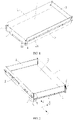
- a battery module includes a battery box and a plurality of battery cells located in the battery box.
- the battery box includes at least two end plates 1 and at least two side plates 2, where an end plate 1 is provided between the adjacent side plates 2, and a cavity 3 of the battery box is enclosed and formed by the end plates 1 and the side plates 2.
- a plurality of battery cells stacked together are provided in the cavity 3, where a large surface of the battery cell faces the end plate 1.
- a plurality of welding members 4 are formed by bending an end portion of the end plate 1 for enclosure for multiple times; and each of the welding members 4 is welded to a corresponding side plate 2.
- each welding member 4 is welded to the corresponding end plate 1 and the side plate 2 to improve the connection strength between the end plate 1 and the side plate 2 adjacent to each other.
- each welding member 4 is formed by bending the end portion of the end plate 1 for enclosure for multiple times. That is, the end plate 1 and the welding member 4 are integrally formed. Therefore, the robustness of the connecting positions the end plate 1 and the side plate 2 are further improved, and the occurrence of open welding at the connecting positions of the end plate 1 and the side plate 2 is reduced or even avoided.
- the battery box can be made of aluminum material, steel material, etc.
- the battery box is preferably made of a steel material in the present embodiment.
- the end portion of the end plate 1 for enclosure is bent twice to form two welding members 4.
- the end portion of the end plate 1 for enclosure is preferably bent twice to form two welding members 4 in the present embodiment. Further, a certain gap may be provided between the two welding members 4. To further improve the robustness of the connection between the welding member 4 and the corresponding side plate 2, and reduce the occurrence of open welding, the two welding members 4 are attached to each other.
- the end portion of the end plate 1 for enclosure is preferably bent twice to form two welding members 4.
- an end surface of the end plate 1 for enclosure is bent in the direction away from the cavity 3 of the battery box, and then continue to be bent in the direction toward its adjacent side plate 2 to form two welding members 4.
- the end portion of the end plate 1 for enclosure is preferably bent in the direction away from the cavity 3 of the battery box to form a first welding member 4.
- the end portion of the end plate 1 for enclosure continues to be bent in the direction away from its adjacent side plate 2 to form a second welding member 4.
- the method of welding may be penetration hot-melt welding.
- the end plate 1 and the side plate 2 are connected by penetration welding.
- a penetration welding area is connected to the welding member 4 and the end plate 1 or the side plate 2.
- a welding seam 5 is located at one side of the side plate 2 away from the welding member 4.
- the welding member 4 may be located inside of the cavity 3 of the battery box. In the present embodiment, in order to improve the energy density, and prevent the welding member 4 from occupying the space in the battery box, the welding member 4 is preferably located outside of the cavity 3 of the battery box.
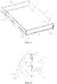
- the end plate 1 in order to further improve the structural strength of the end plate 1 so that the overall structural strength of the battery box is further improved, the end plate 1 is bent to form at least one first stiffening arm 11.
- the first stiffening arm 11 may be provided along a widthwise direction (Y-axis) of the battery box, or along a height direction (Z-axis) of the battery box.
- the bottom portion of the end plate 1 is preferably bent for at least once to form the first stiffening arm 11, and the first stiffening arm 11 is vertical to the side plate 2.
- the connecting member can be connected to a case of a battery pack through the first stiffening arm 11, to fix the battery box and the case of the battery pack, and the connection fixing point of the battery box is provided, where the connecting member may be a bolt.
- the first stiffening arm 11 may be located outside of the cavity structure of the battery box, may also be located inside of the cavity structure of the battery box.
- the first stiffening arm 11 is preferably located outside of the cavity of the battery box.
- the top portion of the end plate 1 is bent at for at least once to form a second stiffening arm 12.
- the second stiffening arm 12 is located outside of the cavity 3 of the battery box, where the second stiffening arm 12 has the same function as the first stiffening arm 11.
- the function of the first stiffening arm 11 has been clearly described above, and will not be repeated here.
- the side plate 2 is bent for multiple times to form a connecting arm 21, and the connecting arm 21 and the end plate 1 are vertically provided.
- the connecting member of the battery box is connected to the case of the battery pack through the connecting arm 21.
- the connecting arm 21 may be located inside of the cavity of the battery box.
- the connecting arm 21 in order to improve the energy density and prevent the connecting arm 21 from occupying the space in the battery box, the connecting arm 21 is located outside of the cavity of the battery box bod.
- the connecting arm 21 may be located at the bottom portion, middle portion or top portion of the side plate 2, to improve the stability of the connection between the connecting arm 21 and the case of the battery pack through the connecting member.
- the connecting arm 21 is located in the middle portion of the side plate 2, where the connecting member may be a bolt.
- the side plate 2 may be bent for one or more times to form the connecting arm 21.
- the connecting arm 21 is formed by bending the side plate 2 twice.
- the connecting arm 21 includes two oppositely provided bending portions 211, where the two bending portions 211 are provided with a plurality of connecting holes 212 corresponding to each other.
- the connecting arm 21 is connected to the case of the battery pack by the connecting members through the plurality of connecting holes 212.
Landscapes
- Chemical & Material Sciences (AREA)
- Chemical Kinetics & Catalysis (AREA)
- Electrochemistry (AREA)
- General Chemical & Material Sciences (AREA)
- Battery Mounting, Suspending (AREA)
- Connection Of Batteries Or Terminals (AREA)
Applications Claiming Priority (2)
| Application Number | Priority Date | Filing Date | Title |
|---|---|---|---|
| CN201822254225.6U CN209016165U (zh) | 2018-12-29 | 2018-12-29 | 电池箱体及电池模组 |
| PCT/CN2019/075822 WO2020133658A1 (zh) | 2018-12-29 | 2019-02-22 | 电池箱体及电池模组 |
Publications (3)
| Publication Number | Publication Date |
|---|---|
| EP3905367A1 EP3905367A1 (en) | 2021-11-03 |
| EP3905367A4 EP3905367A4 (en) | 2022-04-06 |
| EP3905367B1 true EP3905367B1 (en) | 2022-11-23 |
Family
ID=66844290
Family Applications (1)
| Application Number | Title | Priority Date | Filing Date |
|---|---|---|---|
| EP19902042.1A Active EP3905367B1 (en) | 2018-12-29 | 2019-02-22 | Battery box and battery module |
Country Status (6)
| Country | Link |
|---|---|
| US (3) | US11581609B2 (pl) |
| EP (1) | EP3905367B1 (pl) |
| CN (1) | CN209016165U (pl) |
| HU (1) | HUE060824T2 (pl) |
| PL (1) | PL3905367T3 (pl) |
| WO (1) | WO2020133658A1 (pl) |
Cited By (1)
| Publication number | Priority date | Publication date | Assignee | Title |
|---|---|---|---|---|
| PL445741A1 (pl) * | 2023-08-02 | 2025-02-03 | Macro-System Spółka Z Ograniczoną Odpowiedzialnością | Szuflada akumulatorowa bezzałogowego pojazdu kołowego |
Families Citing this family (4)
| Publication number | Priority date | Publication date | Assignee | Title |
|---|---|---|---|---|
| CN112151708A (zh) * | 2019-06-26 | 2020-12-29 | 北京新能源汽车股份有限公司 | 一种电池模组及汽车 |
| CN112310524B (zh) * | 2019-08-08 | 2021-10-12 | 宁德时代新能源科技股份有限公司 | 电池包 |
| CN112563633A (zh) * | 2020-12-10 | 2021-03-26 | 安徽原上草节能环保科技有限公司 | 一种方便更换的新能源电池及其更换方法 |
| KR102911965B1 (ko) * | 2021-08-30 | 2026-01-13 | 주식회사 포스코 | 사이드 프레임 및 배터리 케이스 |
Family Cites Families (9)
| Publication number | Priority date | Publication date | Assignee | Title |
|---|---|---|---|---|
| EP0199279A3 (de) * | 1985-04-22 | 1987-09-23 | Karl Huber Verpackungswerke GmbH + Co. | Verfahren zum Herstellen eines Falzrandes |
| DE3842452A1 (de) * | 1988-12-16 | 1990-06-21 | Schmalbach Lubeca | Aus blech bestehender behaelter |
| US8573683B2 (en) * | 2011-01-07 | 2013-11-05 | Tesla Motors, Inc. | Front rail reinforcement system |
| CN105742539B (zh) * | 2016-04-21 | 2019-04-05 | 宁德时代新能源科技股份有限公司 | 一种电芯模组 |
| WO2018033880A2 (en) * | 2016-08-17 | 2018-02-22 | Shape Corp. | Battery support and protection structure for a vehicle |
| CN206076313U (zh) * | 2016-08-29 | 2017-04-05 | 北京普莱德新能源电池科技有限公司 | 一种新型动力电池包箱体 |
| CN207818670U (zh) * | 2017-12-21 | 2018-09-04 | 宁德时代新能源科技股份有限公司 | 电池模组 |
| CN208189678U (zh) * | 2018-05-03 | 2018-12-04 | 常州普莱德新能源电池科技有限公司 | 一种电动汽车动力电池模组及电动汽车 |
| CN109037527B (zh) * | 2018-07-25 | 2024-03-19 | 江苏正力新能电池技术有限公司 | 一种电池模组 |
-
2018
- 2018-12-29 CN CN201822254225.6U patent/CN209016165U/zh active Active
-
2019
- 2019-02-22 WO PCT/CN2019/075822 patent/WO2020133658A1/zh not_active Ceased
- 2019-02-22 HU HUE19902042A patent/HUE060824T2/hu unknown
- 2019-02-22 PL PL19902042.1T patent/PL3905367T3/pl unknown
- 2019-02-22 EP EP19902042.1A patent/EP3905367B1/en active Active
-
2021
- 2021-06-28 US US17/359,878 patent/US11581609B2/en active Active
-
2023
- 2023-01-04 US US18/149,818 patent/US11749861B2/en active Active
- 2023-07-21 US US18/356,986 patent/US12015166B2/en active Active
Cited By (1)
| Publication number | Priority date | Publication date | Assignee | Title |
|---|---|---|---|---|
| PL445741A1 (pl) * | 2023-08-02 | 2025-02-03 | Macro-System Spółka Z Ograniczoną Odpowiedzialnością | Szuflada akumulatorowa bezzałogowego pojazdu kołowego |
Also Published As
| Publication number | Publication date |
|---|---|
| US11749861B2 (en) | 2023-09-05 |
| US20210328300A1 (en) | 2021-10-21 |
| EP3905367A4 (en) | 2022-04-06 |
| US20240021942A1 (en) | 2024-01-18 |
| PL3905367T3 (pl) | 2023-02-20 |
| US20230145945A1 (en) | 2023-05-11 |
| CN209016165U (zh) | 2019-06-21 |
| HUE060824T2 (hu) | 2023-04-28 |
| US12015166B2 (en) | 2024-06-18 |
| WO2020133658A1 (zh) | 2020-07-02 |
| EP3905367A1 (en) | 2021-11-03 |
| US11581609B2 (en) | 2023-02-14 |
Similar Documents
| Publication | Publication Date | Title |
|---|---|---|
| EP3905367B1 (en) | Battery box and battery module | |
| JP5547805B2 (ja) | 電池スペーサー、電気コア用の保護アセンブリ、およびパワーバッテリー | |
| CN209786120U (zh) | 二次电池和电池模组 | |
| CN102742044A (zh) | 车辆用蓄电池壳体 | |
| CN211017199U (zh) | 电池模块、电池组及装置 | |
| CN108198989A (zh) | 连接构件和充电电池 | |
| KR101412323B1 (ko) | 전지 | |
| CN114024082B (zh) | 电池、电池模组以及电池包 | |
| WO2025195127A1 (zh) | 电池箱体、电池及用电装置 | |
| EP4539243A1 (en) | Battery cell, battery, and electric device | |
| CN222953278U (zh) | 电池装置和用电设备 | |
| CN217562717U (zh) | 箱体及电池插箱 | |
| CN223023455U (zh) | 电池包及电动车辆 | |
| CN216597892U (zh) | 电芯模组的连接结构、电芯模组及电池 | |
| CN117044012A (zh) | 电池单体及其制造方法和制造系统、电池以及用电装置 | |
| JP2013222598A (ja) | 電池 | |
| CN223079259U (zh) | 电池包及电动车辆 | |
| CN115732824A (zh) | 电池包、电池模组和车辆 | |
| CN220895591U (zh) | 锂电池用卷芯组结构及锂电池 | |
| CN221947319U (zh) | 电池及用电装置 | |
| CN217009284U (zh) | 一种极芯内置加强隔板的锂离子电池 | |
| CN215869574U (zh) | 电芯及二次电池 | |
| CN221861467U (zh) | 一种车载电容器铝壳 | |
| EP4717399A1 (en) | Laser welding jig, laser welding system, and welding method using same | |
| CN214505674U (zh) | 一种电池箱体结构 |
Legal Events
| Date | Code | Title | Description |
|---|---|---|---|
| STAA | Information on the status of an ep patent application or granted ep patent |
Free format text: STATUS: THE INTERNATIONAL PUBLICATION HAS BEEN MADE |
|
| PUAI | Public reference made under article 153(3) epc to a published international application that has entered the european phase |
Free format text: ORIGINAL CODE: 0009012 |
|
| STAA | Information on the status of an ep patent application or granted ep patent |
Free format text: STATUS: REQUEST FOR EXAMINATION WAS MADE |
|
| 17P | Request for examination filed |
Effective date: 20210628 |
|
| AK | Designated contracting states |
Kind code of ref document: A1 Designated state(s): AL AT BE BG CH CY CZ DE DK EE ES FI FR GB GR HR HU IE IS IT LI LT LU LV MC MK MT NL NO PL PT RO RS SE SI SK SM TR |
|
| A4 | Supplementary search report drawn up and despatched |
Effective date: 20220310 |
|
| DAV | Request for validation of the european patent (deleted) | ||
| DAX | Request for extension of the european patent (deleted) | ||
| RIC1 | Information provided on ipc code assigned before grant |
Ipc: H01M 50/204 20210101ALI20220303BHEP Ipc: H01M 50/262 20210101ALI20220303BHEP Ipc: H01M 50/244 20210101AFI20220303BHEP |
|
| REG | Reference to a national code |
Ref country code: DE Ref legal event code: R079 Ref document number: 602019022381 Country of ref document: DE Free format text: PREVIOUS MAIN CLASS: H01M0002100000 Ipc: H01M0050244000 |
|
| GRAP | Despatch of communication of intention to grant a patent |
Free format text: ORIGINAL CODE: EPIDOSNIGR1 |
|
| STAA | Information on the status of an ep patent application or granted ep patent |
Free format text: STATUS: GRANT OF PATENT IS INTENDED |
|
| RIC1 | Information provided on ipc code assigned before grant |
Ipc: H01M 50/204 20210101ALI20220830BHEP Ipc: H01M 50/262 20210101ALI20220830BHEP Ipc: H01M 50/244 20210101AFI20220830BHEP |
|
| INTG | Intention to grant announced |
Effective date: 20220915 |
|
| GRAS | Grant fee paid |
Free format text: ORIGINAL CODE: EPIDOSNIGR3 |
|
| GRAA | (expected) grant |
Free format text: ORIGINAL CODE: 0009210 |
|
| STAA | Information on the status of an ep patent application or granted ep patent |
Free format text: STATUS: THE PATENT HAS BEEN GRANTED |
|
| AK | Designated contracting states |
Kind code of ref document: B1 Designated state(s): AL AT BE BG CH CY CZ DE DK EE ES FI FR GB GR HR HU IE IS IT LI LT LU LV MC MK MT NL NO PL PT RO RS SE SI SK SM TR |
|
| REG | Reference to a national code |
Ref country code: GB Ref legal event code: FG4D |
|
| REG | Reference to a national code |
Ref country code: CH Ref legal event code: EP |
|
| REG | Reference to a national code |
Ref country code: DE Ref legal event code: R096 Ref document number: 602019022381 Country of ref document: DE |
|
| REG | Reference to a national code |
Ref country code: AT Ref legal event code: REF Ref document number: 1533708 Country of ref document: AT Kind code of ref document: T Effective date: 20221215 |
|
| REG | Reference to a national code |
Ref country code: IE Ref legal event code: FG4D |
|
| REG | Reference to a national code |
Ref country code: LT Ref legal event code: MG9D |
|
| REG | Reference to a national code |
Ref country code: NL Ref legal event code: MP Effective date: 20221123 |
|
| REG | Reference to a national code |
Ref country code: AT Ref legal event code: MK05 Ref document number: 1533708 Country of ref document: AT Kind code of ref document: T Effective date: 20221123 |
|
| PG25 | Lapsed in a contracting state [announced via postgrant information from national office to epo] |
Ref country code: SE Free format text: LAPSE BECAUSE OF FAILURE TO SUBMIT A TRANSLATION OF THE DESCRIPTION OR TO PAY THE FEE WITHIN THE PRESCRIBED TIME-LIMIT Effective date: 20221123 Ref country code: PT Free format text: LAPSE BECAUSE OF FAILURE TO SUBMIT A TRANSLATION OF THE DESCRIPTION OR TO PAY THE FEE WITHIN THE PRESCRIBED TIME-LIMIT Effective date: 20230323 Ref country code: NO Free format text: LAPSE BECAUSE OF FAILURE TO SUBMIT A TRANSLATION OF THE DESCRIPTION OR TO PAY THE FEE WITHIN THE PRESCRIBED TIME-LIMIT Effective date: 20230223 Ref country code: LT Free format text: LAPSE BECAUSE OF FAILURE TO SUBMIT A TRANSLATION OF THE DESCRIPTION OR TO PAY THE FEE WITHIN THE PRESCRIBED TIME-LIMIT Effective date: 20221123 Ref country code: FI Free format text: LAPSE BECAUSE OF FAILURE TO SUBMIT A TRANSLATION OF THE DESCRIPTION OR TO PAY THE FEE WITHIN THE PRESCRIBED TIME-LIMIT Effective date: 20221123 Ref country code: ES Free format text: LAPSE BECAUSE OF FAILURE TO SUBMIT A TRANSLATION OF THE DESCRIPTION OR TO PAY THE FEE WITHIN THE PRESCRIBED TIME-LIMIT Effective date: 20221123 Ref country code: AT Free format text: LAPSE BECAUSE OF FAILURE TO SUBMIT A TRANSLATION OF THE DESCRIPTION OR TO PAY THE FEE WITHIN THE PRESCRIBED TIME-LIMIT Effective date: 20221123 |
|
| REG | Reference to a national code |
Ref country code: HU Ref legal event code: AG4A Ref document number: E060824 Country of ref document: HU |
|
| PG25 | Lapsed in a contracting state [announced via postgrant information from national office to epo] |
Ref country code: RS Free format text: LAPSE BECAUSE OF FAILURE TO SUBMIT A TRANSLATION OF THE DESCRIPTION OR TO PAY THE FEE WITHIN THE PRESCRIBED TIME-LIMIT Effective date: 20221123 Ref country code: LV Free format text: LAPSE BECAUSE OF FAILURE TO SUBMIT A TRANSLATION OF THE DESCRIPTION OR TO PAY THE FEE WITHIN THE PRESCRIBED TIME-LIMIT Effective date: 20221123 Ref country code: IS Free format text: LAPSE BECAUSE OF FAILURE TO SUBMIT A TRANSLATION OF THE DESCRIPTION OR TO PAY THE FEE WITHIN THE PRESCRIBED TIME-LIMIT Effective date: 20230323 Ref country code: HR Free format text: LAPSE BECAUSE OF FAILURE TO SUBMIT A TRANSLATION OF THE DESCRIPTION OR TO PAY THE FEE WITHIN THE PRESCRIBED TIME-LIMIT Effective date: 20221123 Ref country code: GR Free format text: LAPSE BECAUSE OF FAILURE TO SUBMIT A TRANSLATION OF THE DESCRIPTION OR TO PAY THE FEE WITHIN THE PRESCRIBED TIME-LIMIT Effective date: 20230224 |
|
| P01 | Opt-out of the competence of the unified patent court (upc) registered |
Effective date: 20230516 |
|
| PG25 | Lapsed in a contracting state [announced via postgrant information from national office to epo] |
Ref country code: NL Free format text: LAPSE BECAUSE OF FAILURE TO SUBMIT A TRANSLATION OF THE DESCRIPTION OR TO PAY THE FEE WITHIN THE PRESCRIBED TIME-LIMIT Effective date: 20221123 |
|
| PG25 | Lapsed in a contracting state [announced via postgrant information from national office to epo] |
Ref country code: SM Free format text: LAPSE BECAUSE OF FAILURE TO SUBMIT A TRANSLATION OF THE DESCRIPTION OR TO PAY THE FEE WITHIN THE PRESCRIBED TIME-LIMIT Effective date: 20221123 Ref country code: RO Free format text: LAPSE BECAUSE OF FAILURE TO SUBMIT A TRANSLATION OF THE DESCRIPTION OR TO PAY THE FEE WITHIN THE PRESCRIBED TIME-LIMIT Effective date: 20221123 Ref country code: EE Free format text: LAPSE BECAUSE OF FAILURE TO SUBMIT A TRANSLATION OF THE DESCRIPTION OR TO PAY THE FEE WITHIN THE PRESCRIBED TIME-LIMIT Effective date: 20221123 Ref country code: DK Free format text: LAPSE BECAUSE OF FAILURE TO SUBMIT A TRANSLATION OF THE DESCRIPTION OR TO PAY THE FEE WITHIN THE PRESCRIBED TIME-LIMIT Effective date: 20221123 Ref country code: CZ Free format text: LAPSE BECAUSE OF FAILURE TO SUBMIT A TRANSLATION OF THE DESCRIPTION OR TO PAY THE FEE WITHIN THE PRESCRIBED TIME-LIMIT Effective date: 20221123 |
|
| REG | Reference to a national code |
Ref country code: DE Ref legal event code: R097 Ref document number: 602019022381 Country of ref document: DE |
|
| PG25 | Lapsed in a contracting state [announced via postgrant information from national office to epo] |
Ref country code: SK Free format text: LAPSE BECAUSE OF FAILURE TO SUBMIT A TRANSLATION OF THE DESCRIPTION OR TO PAY THE FEE WITHIN THE PRESCRIBED TIME-LIMIT Effective date: 20221123 Ref country code: AL Free format text: LAPSE BECAUSE OF FAILURE TO SUBMIT A TRANSLATION OF THE DESCRIPTION OR TO PAY THE FEE WITHIN THE PRESCRIBED TIME-LIMIT Effective date: 20221123 |
|
| PG25 | Lapsed in a contracting state [announced via postgrant information from national office to epo] |
Ref country code: MC Free format text: LAPSE BECAUSE OF FAILURE TO SUBMIT A TRANSLATION OF THE DESCRIPTION OR TO PAY THE FEE WITHIN THE PRESCRIBED TIME-LIMIT Effective date: 20221123 |
|
| PLBE | No opposition filed within time limit |
Free format text: ORIGINAL CODE: 0009261 |
|
| REG | Reference to a national code |
Ref country code: CH Ref legal event code: PL |
|
| STAA | Information on the status of an ep patent application or granted ep patent |
Free format text: STATUS: NO OPPOSITION FILED WITHIN TIME LIMIT |
|
| REG | Reference to a national code |
Ref country code: BE Ref legal event code: MM Effective date: 20230228 |
|
| PG25 | Lapsed in a contracting state [announced via postgrant information from national office to epo] |
Ref country code: LU Free format text: LAPSE BECAUSE OF NON-PAYMENT OF DUE FEES Effective date: 20230222 Ref country code: LI Free format text: LAPSE BECAUSE OF NON-PAYMENT OF DUE FEES Effective date: 20230228 Ref country code: CH Free format text: LAPSE BECAUSE OF NON-PAYMENT OF DUE FEES Effective date: 20230228 |
|
| 26N | No opposition filed |
Effective date: 20230824 |
|
| PG25 | Lapsed in a contracting state [announced via postgrant information from national office to epo] |
Ref country code: SI Free format text: LAPSE BECAUSE OF FAILURE TO SUBMIT A TRANSLATION OF THE DESCRIPTION OR TO PAY THE FEE WITHIN THE PRESCRIBED TIME-LIMIT Effective date: 20221123 |
|
| REG | Reference to a national code |
Ref country code: IE Ref legal event code: MM4A |
|
| PG25 | Lapsed in a contracting state [announced via postgrant information from national office to epo] |
Ref country code: IE Free format text: LAPSE BECAUSE OF NON-PAYMENT OF DUE FEES Effective date: 20230222 |
|
| PG25 | Lapsed in a contracting state [announced via postgrant information from national office to epo] |
Ref country code: BE Free format text: LAPSE BECAUSE OF NON-PAYMENT OF DUE FEES Effective date: 20230228 |
|
| PG25 | Lapsed in a contracting state [announced via postgrant information from national office to epo] |
Ref country code: IT Free format text: LAPSE BECAUSE OF FAILURE TO SUBMIT A TRANSLATION OF THE DESCRIPTION OR TO PAY THE FEE WITHIN THE PRESCRIBED TIME-LIMIT Effective date: 20221123 |
|
| REG | Reference to a national code |
Ref country code: DE Ref legal event code: R081 Ref document number: 602019022381 Country of ref document: DE Owner name: CONTEMPORARY AMPEREX TECHNOLOGY (HONG KONG) LI, HK Free format text: FORMER OWNER: CONTEMPORARY AMPEREX TECHNOLOGY CO., LIMITED, NINGDE, FUJIAN, CN |
|
| REG | Reference to a national code |
Ref country code: GB Ref legal event code: 732E Free format text: REGISTERED BETWEEN 20240822 AND 20240828 |
|
| REG | Reference to a national code |
Ref country code: HU Ref legal event code: GB9C Owner name: CONTEMPORARY AMPEREX TECHNOLOGY (HONG KONG) LIMITED, HK Free format text: FORMER OWNER(S): CONTEMPORARY AMPEREX TECHNOLOGY CO., LIMITED, CN Ref country code: HU Ref legal event code: FH1C Free format text: FORMER REPRESENTATIVE(S): SBGK SZABADALMI UEGYVIVOEI IRODA, HU Representative=s name: DANUBIA SZABADALMI ES JOGI IRODA KFT., HU |
|
| PG25 | Lapsed in a contracting state [announced via postgrant information from national office to epo] |
Ref country code: BG Free format text: LAPSE BECAUSE OF FAILURE TO SUBMIT A TRANSLATION OF THE DESCRIPTION OR TO PAY THE FEE WITHIN THE PRESCRIBED TIME-LIMIT Effective date: 20221123 |
|
| PG25 | Lapsed in a contracting state [announced via postgrant information from national office to epo] |
Ref country code: BG Free format text: LAPSE BECAUSE OF FAILURE TO SUBMIT A TRANSLATION OF THE DESCRIPTION OR TO PAY THE FEE WITHIN THE PRESCRIBED TIME-LIMIT Effective date: 20221123 |
|
| PGFP | Annual fee paid to national office [announced via postgrant information from national office to epo] |
Ref country code: DE Payment date: 20241231 Year of fee payment: 7 |
|
| PGFP | Annual fee paid to national office [announced via postgrant information from national office to epo] |
Ref country code: GB Payment date: 20250102 Year of fee payment: 7 |
|
| PG25 | Lapsed in a contracting state [announced via postgrant information from national office to epo] |
Ref country code: CY Free format text: LAPSE BECAUSE OF FAILURE TO SUBMIT A TRANSLATION OF THE DESCRIPTION OR TO PAY THE FEE WITHIN THE PRESCRIBED TIME-LIMIT; INVALID AB INITIO Effective date: 20190222 |
|
| PG25 | Lapsed in a contracting state [announced via postgrant information from national office to epo] |
Ref country code: TR Free format text: LAPSE BECAUSE OF FAILURE TO SUBMIT A TRANSLATION OF THE DESCRIPTION OR TO PAY THE FEE WITHIN THE PRESCRIBED TIME-LIMIT Effective date: 20221123 |
|
| PGFP | Annual fee paid to national office [announced via postgrant information from national office to epo] |
Ref country code: FR Payment date: 20251231 Year of fee payment: 8 |
|
| PGFP | Annual fee paid to national office [announced via postgrant information from national office to epo] |
Ref country code: PL Payment date: 20251128 Year of fee payment: 8 |
|
| PGFP | Annual fee paid to national office [announced via postgrant information from national office to epo] |
Ref country code: HU Payment date: 20260130 Year of fee payment: 8 |