EP3904539B1 - Verfahren zur kreislaufführung metallurgischer schlacken und verwendung einer schlacke hierfür - Google Patents
Verfahren zur kreislaufführung metallurgischer schlacken und verwendung einer schlacke hierfür Download PDFInfo
- Publication number
- EP3904539B1 EP3904539B1 EP21170615.5A EP21170615A EP3904539B1 EP 3904539 B1 EP3904539 B1 EP 3904539B1 EP 21170615 A EP21170615 A EP 21170615A EP 3904539 B1 EP3904539 B1 EP 3904539B1
- Authority
- EP
- European Patent Office
- Prior art keywords
- slag
- metallurgical
- metallurgical slag
- energy source
- reductant
- Prior art date
- Legal status (The legal status is an assumption and is not a legal conclusion. Google has not performed a legal analysis and makes no representation as to the accuracy of the status listed.)
- Active
Links
Images


Classifications
-
- C—CHEMISTRY; METALLURGY
- C21—METALLURGY OF IRON
- C21B—MANUFACTURE OF IRON OR STEEL
- C21B3/00—General features in the manufacture of pig-iron
- C21B3/04—Recovery of by-products, e.g. slag
-
- C—CHEMISTRY; METALLURGY
- C21—METALLURGY OF IRON
- C21C—PROCESSING OF PIG-IRON, e.g. REFINING, MANUFACTURE OF WROUGHT-IRON OR STEEL; TREATMENT IN MOLTEN STATE OF FERROUS ALLOYS
- C21C5/00—Manufacture of carbon-steel, e.g. plain mild steel, medium carbon steel or cast steel or stainless steel
- C21C5/28—Manufacture of steel in the converter
- C21C5/42—Constructional features of converters
- C21C5/46—Details or accessories
- C21C5/466—Charging device for converters
-
- C—CHEMISTRY; METALLURGY
- C21—METALLURGY OF IRON
- C21C—PROCESSING OF PIG-IRON, e.g. REFINING, MANUFACTURE OF WROUGHT-IRON OR STEEL; TREATMENT IN MOLTEN STATE OF FERROUS ALLOYS
- C21C5/00—Manufacture of carbon-steel, e.g. plain mild steel, medium carbon steel or cast steel or stainless steel
- C21C5/52—Manufacture of steel in electric furnaces
- C21C5/527—Charging of the electric furnace
-
- C—CHEMISTRY; METALLURGY
- C21—METALLURGY OF IRON
- C21C—PROCESSING OF PIG-IRON, e.g. REFINING, MANUFACTURE OF WROUGHT-IRON OR STEEL; TREATMENT IN MOLTEN STATE OF FERROUS ALLOYS
- C21C7/00—Treating molten ferrous alloys, e.g. steel, not covered by groups C21C1/00 - C21C5/00
- C21C7/04—Removing impurities by adding a treating agent
- C21C7/076—Use of slags or fluxes as treating agents
-
- C—CHEMISTRY; METALLURGY
- C22—METALLURGY; FERROUS OR NON-FERROUS ALLOYS; TREATMENT OF ALLOYS OR NON-FERROUS METALS
- C22B—PRODUCTION AND REFINING OF METALS; PRETREATMENT OF RAW MATERIALS
- C22B7/00—Working up raw materials other than ores, e.g. scrap, to produce non-ferrous metals and compounds thereof; Methods of a general interest or applied to the winning of more than two metals
- C22B7/04—Working-up slag
-
- C—CHEMISTRY; METALLURGY
- C21—METALLURGY OF IRON
- C21B—MANUFACTURE OF IRON OR STEEL
- C21B2400/00—Treatment of slags originating from iron or steel processes
- C21B2400/04—Specific shape of slag after cooling
-
- C—CHEMISTRY; METALLURGY
- C21—METALLURGY OF IRON
- C21C—PROCESSING OF PIG-IRON, e.g. REFINING, MANUFACTURE OF WROUGHT-IRON OR STEEL; TREATMENT IN MOLTEN STATE OF FERROUS ALLOYS
- C21C5/00—Manufacture of carbon-steel, e.g. plain mild steel, medium carbon steel or cast steel or stainless steel
- C21C5/28—Manufacture of steel in the converter
- C21C5/42—Constructional features of converters
- C21C5/46—Details or accessories
- C21C5/466—Charging device for converters
- C21C2005/4666—Charging device for converters for charging with organic contaminated scrap
-
- C—CHEMISTRY; METALLURGY
- C21—METALLURGY OF IRON
- C21C—PROCESSING OF PIG-IRON, e.g. REFINING, MANUFACTURE OF WROUGHT-IRON OR STEEL; TREATMENT IN MOLTEN STATE OF FERROUS ALLOYS
- C21C5/00—Manufacture of carbon-steel, e.g. plain mild steel, medium carbon steel or cast steel or stainless steel
- C21C5/52—Manufacture of steel in electric furnaces
- C21C5/527—Charging of the electric furnace
- C21C2005/5282—Charging of the electric furnace with organic contaminated scrap
-
- Y—GENERAL TAGGING OF NEW TECHNOLOGICAL DEVELOPMENTS; GENERAL TAGGING OF CROSS-SECTIONAL TECHNOLOGIES SPANNING OVER SEVERAL SECTIONS OF THE IPC; TECHNICAL SUBJECTS COVERED BY FORMER USPC CROSS-REFERENCE ART COLLECTIONS [XRACs] AND DIGESTS
- Y02—TECHNOLOGIES OR APPLICATIONS FOR MITIGATION OR ADAPTATION AGAINST CLIMATE CHANGE
- Y02P—CLIMATE CHANGE MITIGATION TECHNOLOGIES IN THE PRODUCTION OR PROCESSING OF GOODS
- Y02P10/00—Technologies related to metal processing
- Y02P10/20—Recycling
-
- Y—GENERAL TAGGING OF NEW TECHNOLOGICAL DEVELOPMENTS; GENERAL TAGGING OF CROSS-SECTIONAL TECHNOLOGIES SPANNING OVER SEVERAL SECTIONS OF THE IPC; TECHNICAL SUBJECTS COVERED BY FORMER USPC CROSS-REFERENCE ART COLLECTIONS [XRACs] AND DIGESTS
- Y02—TECHNOLOGIES OR APPLICATIONS FOR MITIGATION OR ADAPTATION AGAINST CLIMATE CHANGE
- Y02W—CLIMATE CHANGE MITIGATION TECHNOLOGIES RELATED TO WASTEWATER TREATMENT OR WASTE MANAGEMENT
- Y02W30/00—Technologies for solid waste management
- Y02W30/50—Reuse, recycling or recovery technologies
Definitions
- the invention relates to a method for circulating metallurgical slag according to the preamble of claim 1.
- the invention also relates to the use in said method according to the preamble of claim 15.
- a metallurgical slag is a molten rock that essentially consists of non-metallic components of the input materials, e.g. a metal ore used (gangue). It can consist of various accompanying minerals or contain several mineral phases, such as sulphides (magnetic gravel, alabandine, zinc blende, wurtzite), oxides (spinel, magnetite), silicates (fayalite, merwinite).
- the composition depends strongly on whether the slag was produced in a ferrous or non-ferrous metallurgical process.
- slag with a defined composition that is used as an aid in the processing of molten metal.
- Metallurgical slags can fulfill different functions. Some slags are used in the metal extraction process to cover the metal against possible oxidation. Other slags serve to absorb the accompanying elements, namely the elements that are not excreted via the gas phase. Metallurgical slags are used in an electric arc furnace in order to reduce thermal radiation losses.
- Metallurgical slags can occur in almost all metallurgical manufacturing and processing processes. Based on their production method, they are divided into steel mill, metallurgical and blast furnace slag.
- Iron ores are naturally occurring chemical iron compounds.
- the economically important iron ores are mostly iron oxides or iron carbonates.
- the most important iron ore minerals are magnetite (Fe 3 O 4 , up to 72% iron content), hematite (Fe 2 O 3 , up to 70% iron content) and siderite (FeCO 3 , up to 48% iron content).
- Coke, pulverized coal and other substances are used as reducing agents in the blast furnace process.
- Coke is a compound with a high carbon content that is produced from hard coal via pyrolysis.
- coke also serves as a supporting framework for the process.
- Alternative reducing agents such as pulverized coal, waste plastics, etc. can be used as reducing agents via the tuyeres.
- the additives added serve to bind the impurities contained in the iron ore. At the end of the blast furnace process, these surcharges and former impurities in the iron ore accumulate as blast furnace slag, which is finally separated from the pig iron.
- the uppermost zone is the so-called preheating zone, which has a temperature of approx. 200°C.
- the iron ore or reducing agent is dried and preheated.
- the next zone is the so-called reduction zone at temperatures of 400°C to 800°C. At these temperatures, the iron ore is still in the solid state. In the lower (hot) area of the reduction zone, from a temperature of approx. 700°C, the iron ore reacts with carbon monoxide, which rises from the conversion zone and reduces the iron oxides present to iron. In this redox reaction, the carbon monoxide reacts with iron oxides to form iron and carbon dioxide.
- the next (lower) zone is the so-called direct reduction zone (reaction zone) at temperatures from 1000°C to 1600°C.
- reaction zone the so-called direct reduction zone (reaction zone) at temperatures from 1000°C to 1600°C.
- the not yet fully reduced iron oxide reacts with solid carbon to form pure metallic iron and, on the other hand, the reducing agent reacts with the oxygen blown in, which is blown in in the melting zone, to form carbon dioxide.
- Carbon dioxide reacts with carbon to form carbon monoxide.
- a temperature of at least 1000 °C is required for the reaction. Higher temperatures shift the equilibrium to the product side due to the endothermic reaction, while lower temperatures favor the formation of carbon dioxide and carbon.
- the iron produced is in the form of pig iron, which is subjected to further metallurgical processing.
- plastic waste is also used as a reducing agent in a blast furnace process. This has the advantage that the plastic waste does not have to be landfilled and, in contrast to coke, is sulphur-free. In addition, the use of plastic waste in the blast furnace process reduces CO2 and SO2 emissions.
- blast furnace slag is also used as a plastic filler for the purpose of functionalization.
- ⁇ -wollastonite As a plastic filler.
- the ⁇ -wollastonite is added to a plastic to modify the properties of the end product at will.
- a finely crystalline, synthetically produced ⁇ -wollastonite with a BET surface area of 1-100 m 2 /g and a high proportion of white is used.
- the brightness is about 93% compared to the standard white of magnesium oxide.
- the filler is therefore particularly suitable as a white pigment for paints and coatings.
- plastic properties can also be modified in a controlled manner by adding fillers.
- a plastic composite which consists of 60-98% polypropylene and 1-30% blast furnace slag.
- a silane coupling agent (1-10%) is added to better connect the two components.
- the blast furnace slag used has a material density of 950-970 kg/m 3 and contains particles in the size range of 1-10 ⁇ m.
- the ignition time is extended by more than 25%.
- the yield strength of the composite is increased by more than 20%.
- a plastic composite modified in this way is used to manufacture everyday objects, plastic pipes, but also in the automotive industry.
- thermoplastics such as polypropylene and polystyrene
- blast furnace slag A finely ground blast furnace slag with a particle size of 1-100 ⁇ m is added to the plastic.
- the degree of filling is at most 30% by weight.
- the resulting plastic composite has increased shear viscosity and elasticity. The strength is reduced by the addition of the filler.
- blast furnace slag increases the crystallization temperature and inhibits the crystallization process of the polypropylene.
- patent documents U.S. 2005/257644 A1 and U.S. 6,174,347 B1 also disclose a method for circulating metallurgical slags, in which a slag produced in a metallurgical process is mixed with an energy source and/or reducing agent and a composite material is produced in the process.
- the object of the invention is to create a method for recycling metallurgical slag.
- a further object of the invention is to create a use in said method.
- the invention provides that the metallurgical slag is mixed with an energy source or reducing agent. The mixture is then put to secondary use. At the end of life, it is returned to the metallurgical process and both the slag and the energy carrier and/or the reducing agent are used in the metallurgical process.
- the slags are exactly the specific fed to the circuit from which they originate, eg the blast furnace slag is added to the blast furnace.
- a targeted return of a slag is operated, so that not just any filler enters the metallurgical cycle, but the slag that is also present again at the end of the metallurgical process.
- the filler used in this way is in no way harmful to the metallurgical process. Rather, a recirculated slag is useful from a number of aspects. Any metallurgical process in which slag is used relies on a large amount of slag. For example, when starting up blast furnaces, even lumpy slag is added in order to have enough slag available.
- the slag acts as a flux if it is returned as a filler and it is easier to melt it since the slag is a solidified melt.
- the slag is able to absorb substances such as sulfur or alkalis, since it is not yet saturated with the substances even after repeated passage or recycling.
- All slags that are produced in metallurgical processes are suitable for this process. It may be blast furnace slag that is produced during the production of pig iron through thermal reduction processes in the blast furnace. It can consist of the non-metallic components of the iron ore, components of the reducing agent or coal. It can also contain aggregates such as limestone or dolomite.
- Steelworks slags such as converter slag or LD slag, electric furnace slag, stainless steel slag or the secondary metallurgical slag that is produced in the after-treatment of crude steel, can also be used.
- metallurgical slag which includes slags from the surcharges of smelting copper, zinc, lead and chromium ores with iron as a replacement metal, can be used.
- Carbon-containing compounds that have a dual function are referred to here as energy carriers and/or reducing agents. On the one hand they serve to reduce the iron ore, on the other hand their combustion releases energy that is used in the blast furnace process.
- Organic or inorganic energy carriers can be used as additional fillers, e.g. coke flour, carbon flour, wood flour or the like.
- the mixture can be a composite material.
- the composite material is put to secondary use.
- Secondary use includes the usual processing steps, such as casting, molding and the like, which lead to the production of a shaped body.
- the shaped body produced in this way is then either further processed industrially, for example in the electronics, mobility or packaging industry, or it will reach the end user as a commodity.
- the shaped body produced from the mixture mentioned is returned to the blast furnace and thermally split into its components.
- the slag and the energy source and/or the reducing agent are fed to the iron extraction and/or processing process.
- the energy source and/or the reducing agent is used and consumed in the blast furnace to reduce the iron ore.
- the slag is regenerated and fed into a new energy cycle as a mineral filler.
- the regenerated slag can also be used in other metallurgical processes, for example in electric arc furnaces or in secondary metallurgy.
- the advantage here is that the resources are used sparingly and are fed back into the energy cycle at the end. In this way, the production of new substances is avoided and the disposal of used plastic waste is prevented.
- the addition of degraded mineral substances such as calcium carbonate and talc as a filler can be replaced by a filler that is kept in circulation. This conserves resources and the energy used in processing can be saved.
- the energy carrier used and/or the reducing agent can be a polymeric compound, in particular a carbon-based plastic.
- a plastic can be, for example, a thermoplastic, duroplastic and/or an elastomer.
- thermoplastics examples include polypropylene, polystyrene, polyvinyl chloride, polyethylene, polyethylene terephthalate, polyether ether ketone.
- duroplastics are, for example, bakelite, polyamide, vinyl ester, epoxy resin.
- elastomers are, for example, polybutadiene, chloroprene, neoprene, nitrile, ethylene vinyl acetate.
- Metallurgical slag is a mixture of substances of mineral origin. It mainly consists of oxidic components. The oxides contained therein can be acidic, basic or amphoteric. Acidic oxides are mostly non-metallic oxides such as SiO2. Metal oxides are usually referred to as basic oxides, such as MgO, CaO, NazO, K 2 O. Amphoteric oxides are oxides that can show partly acidic partly basic behavior depending on the reactant, such as Al 2 O 3 .
- the slag according to the invention can, for example, have the following chemical composition: SiO2 28.0 - 45.0% Al2O3 6.0 - 17.0% CaO 26.0 - 45.0% MgO 7-12% Mn 0.5 - 3.0% FeO ⁇ 1.0% Fe tot. ⁇ 1% TiO2 ⁇ 1.8% Na2O ⁇ 0.6% K2O ⁇ 2.0% S total ⁇ 1.5%
- Such a slag can be a blast-furnace slag or any other metallurgical slag that is optionally adjusted or optimized to this composition.
- the slag can be finely ground using a ball milling and/or jet milling process.
- the resulting particles have a grain size of less than 20 ⁇ m (d98 ⁇ 20 ⁇ m).
- the slag can be subjected to a sifting process. This minimizes the abrasive properties.
- the abrasiveness can particularly preferably have a value of less than 20 mg according to the Einlehner 1000 test. This value can be measured in an abrasion test device such as DE2033592 be measured.
- the slag produced in this way has a maximum BET surface area of 10 m2/g.
- the filler produced in this way can be processed directly by the plastics manufacturer into finished compound materials or master batches.
- plastic is labeled with regard to its filler in order to enable it to be sorted according to type and returned to the specific metallurgical process.
- the invention thus relates in particular to a method for recycling metallurgical slags, in which a slag produced in a metallurgical process is mixed with an energy source and/or reducing agent and a composite material is produced in the process, the composite material being used for secondary purposes and at the end of its life in the appropriate metallurgical process, the composite material on the one hand providing slag and on the other hand energy and/or having a reducing effect, with the energy carrier and/or the reducing agent being consumed in the metallurgical process and the metallurgical slag being separated off at the end of the process and fed into a new cycle.
- the metallurgical slag is mixed with the energy source and/or reducing agent, the metallurgical slag being a blast furnace slag. It is also advantageous if the metallurgical slag is mixed with the energy carrier and/or reducing agent, the metallurgical slag being a steel works slag, in particular an LD slag.
- the metallurgical slag is mixed with the energy carrier and/or reducing agent, the metallurgical slag being a metallurgical slag.
- the metallurgical slag is ground and/or classified in order to set a desired particle size range and/or a desired particle size distribution.
- the metallurgical slag is finely ground. After fine grinding, the metallurgical slag is advantageously subjected to a classification process in order to set a defined grain size range.
- An advantageous embodiment provides that a metallurgical slag is used which has a particle size of less than 20 ⁇ m.
- a metallurgical slag which has a BET surface area of less than or equal to 10 m 2 /g, as disclosed in the appended set of claims.
- a further advantageous embodiment provides that a metallurgical slag is used which has the following chemical composition: SiO2 28.0 - 45.0% Al2O3 6.0 - 17.0% CaO 26.0 - 45.0% MgO 7-12% Mn 0.5 - 3.0% FeO ⁇ 1.0% Fe tot. ⁇ 1% TiO2 ⁇ 1.8% Na2O ⁇ 0.6% K2O ⁇ 2.0% S total ⁇ 1.5%
- a metallurgical slag which has a silane-free and/or coupler-free, in particular silane coupler-free, composition.
- the metallurgical slag is mixed with the energy carrier and/or reducing agent, the energy carrier and/or reducing agent being a carbon-based polymeric compound, e.g., a thermoplastic, a thermoset and/or an elastomer.
- the energy carrier and/or reducing agent being a carbon-based polymeric compound, e.g., a thermoplastic, a thermoset and/or an elastomer.
- the metallurgical slag is mixed with the energy carrier and/or reducing agent, with the energy carrier and/or the reducing agent having a shaping effect.
- the metallurgical slag is compounded with an energy carrier plastic as a functional filler.
- One embodiment provides that the composite material produced is processed into a shaped body.
- a further embodiment provides that the composite material produced is identified with regard to the slag used.
- a particularly advantageous embodiment provides a mineral filler for use in a circulation process, the filler being a metallurgical slag, the metallurgical slag being silane-free and/or coupler-free, in particular silane coupler-free, and having the following chemical composition: SiO2 28.0 - 45.0% Al2O3 6.0 - 17.0% CaO 26.0 - 45.0% MgO 7-12% Mn 0.5 - 3.0% FeO ⁇ 1.0% Fe tot. ⁇ 1% TiO2 ⁇ 1.8% Na2O ⁇ 0.6% K2O ⁇ 2.0% S total ⁇ 1.5%
- the metallurgical slag is a blast furnace slag.
- the metallurgical slag is a steelworks slag, in particular an LD slag.
- the metallurgical slag is a metallurgical slag.
- the metallurgical slag is finely ground and/or classified and has a particle size of less than 20 ⁇ m.
- the metallurgical slag has a BET surface area of less than or equal to 10 m 2 /g.
- the metallurgical slag has a low abrasiveness of less than 20 mg according to the Einlehner 1000 test.
- Another non-claimed embodiment provides for the use of a non-silanized slag as a plastic filler.
- the slag according to the invention is fed into a circular economy by being added to a plastic as a filler ( figure 1 ).
- the plastic containing the slag is used in the manufacture of various plastic products. This can be, for example, household products, packaging, industrial components, plastic items for the automotive industry or the like.
- the addition of the slag improves the mechanical properties of the respective plastic products and/or the service life. This can be an improvement in hardness, strength, workability or the like.
- the plastic products containing slag are put to use.
- the plastic products reach the waste phase, where they are processed for recycling. They are then fed into a steel production circuit.
- the plastic and the slag are thermally separated from each other.
- the plastic is added to the steel production process as an energy carrier and/or reducing agent.
- the slag is regenerated and can be fed into a new cycle.
- the slag Before being used as a mineral filler, the slag can be processed, for example, by grinding ( figure 2 ). It is then fed into a plastic cycle as a mineral filler ( figure 3 ). A plastic raw material, e.g. B. a plastic granulate, mixed with the slag. This process is called compounding.
- a plastic raw material e.g. B. a plastic granulate
- the plastic granules compounded in this way are subjected to one or more processing steps which lead to a finished plastic product. This can involve processes such as injection molding, extrusion or blow molding.
- Plastics processing can include such processes as single screw, extrusion, filtration or degassing. The aim of such processing is to produce plastic granules that can be subjected to renewed compounding and processing.
- a so-called masterbatch is produced during compounding, for this purpose a mass flow proportion of 80 of a filler and a mass flow proportion of 20 of a plastic are combined as a masterbatch with a mass flow proportion of 100 ( figure 4 ).
- the masterbatch produced in this way is used as the basis for the manufacture of the later plastic products.
- plastic e.g. B. in the amount of 150 parts by mass
- the finished end product can thus contain 250 parts by weight. Accordingly, at the end of its service life, a mass flow fraction of 250 is fed into a blast furnace process. In the blast furnace process, a mass flow rate of 170% is discharged in the form of plastic that is thermally recycled. A solid mass flow fraction of 80% remains in the form of blast furnace slag from the compound material. This solids mass flow fraction is fed back into the cycle, where it is processed into a masterbatch with a plastic fraction of 20%.
- the slag according to the invention is a blast furnace slag which has the following chemical composition: SiOz 36.7% Al2O3 _ 12.9% CaO 34.9% Mg0 10.5% Mn 0.8% Fe0 0.4% Fe tot. 0.4% TiOz 1.1% NazO 0.3% K2O 1.2% S total . 0.8%
- Fe tot refers to the total proportion of elemental iron in any form (with the exception of oxidic iron, which is separately identified as FeO).
- S tot denotes the total proportion of elemental sulfur.
- the blast furnace slag is separated from the metal in the molten state and cooled in the liquid state: either with water or by decanting. According to the cooled Finely ground slag using a ball milling and/or jet milling process. 98% of the particles have a grain size below 20 ⁇ m. The abrasiveness is clearly minimized here.
- the blast furnace slag produced according to the invention is used as a mineral filler in the next step. To do this, it is mixed with an energy source that is solid at room temperature and/or a reducing agent that is in powder form.
- an energy source that is solid at room temperature and/or a reducing agent that is in powder form.
- thermoplastics it is preferably dispersed into a polymer melt on a twin-screw compounding plant and then granulated to form conventional plastic granules (approx. 3-5 mm in diameter) on the hot strand or via underwater granulation.
- duromers they can be mixed in and dispersed directly into resins at room temperature and using stirring devices as are customary in the coatings industry.
- the resulting composite material is subjected to other processing steps that lead to a shaped body. As a rule, this involves discontinuous injection molding or continuous extrusion.
- the finished shaped body is introduced into the utilization cycle, collected at the end of its life and finally fed into the blast furnace process.
- the composite material is thermally split into the blast furnace slag and the energy carrier and/or the reducing agent.
- the energy carrier and/or the reducing agent is consumed in the production of the metal.
- the blast furnace slag is separated at the end and fed into a new cycle.
Landscapes
- Chemical & Material Sciences (AREA)
- Engineering & Computer Science (AREA)
- Materials Engineering (AREA)
- Metallurgy (AREA)
- Organic Chemistry (AREA)
- Manufacturing & Machinery (AREA)
- Life Sciences & Earth Sciences (AREA)
- Environmental & Geological Engineering (AREA)
- General Life Sciences & Earth Sciences (AREA)
- Geology (AREA)
- Mechanical Engineering (AREA)
- Processing Of Solid Wastes (AREA)
- Separation, Recovery Or Treatment Of Waste Materials Containing Plastics (AREA)
- Curing Cements, Concrete, And Artificial Stone (AREA)
- Furnace Details (AREA)
Description
- Die Erfindung betrifft ein Verfahren zur Kreislaufführung metallurgischer Schlacken nach dem Oberbegriff des Anspruchs 1.
- Die Erfindung betrifft ebenfalls die Verwendung im genannten Verfahren nach dem Oberbegriff des Anspruchs 15.
- Metallurgische Schlacken sind bekannt. Eine metallurgische Schlacke ist eine Gesteinsschmelze, die im Wesentlichen aus nichtmetallischen Komponenten der Einsatzstoffe z.B. eines eingesetzten Metallerzes (Gangart) besteht. Sie kann aus verschiedenen Begleitmineralen bestehen bzw. mehrere Mineralphasen enthalten, wie zum Beispiel Sulfide (Magnetkies, Alabandin, Zinkblende, Wurtzit), Oxide (Spinell, Magnetit), Silikate (Fayalith, Merwinit). Die Zusammensetzung hängt stark davon ab, ob die Schlacke in einem eisenmetallurgischen oder nichteisenmetallurgischen Prozess erzeugt worden ist. Zudem gibt es Schlacken mit einer definierten Zusammensetzung, die als Hilfsmittel in der Verarbeitung von Metallschmelzen eingesetzt werden.
- Metallurgische Schlacken können verschiedene Funktionen erfüllen. Einige Schlacken werden im Metallgewinnungsprozess verwendet, um das Metall gegen mögliche Oxidation abzudecken. Andere Schlacken dienen dazu, die Begleitelemente aufzunehmen und zwar die Elemente, die über die Gasphase nicht ausgehschieden werden. In einem Elektrolichtbogenofen werden metallurgische Schlacken eingesetzt, um die thermische Verluststrahlung zu reduzieren.
- Metallurgische Schlacken können bei fast allen metallurgischen Herstellungs- und Verarbeitungsprozessen entstehen. Anhand ihrer Herstellungsmethode werden sie in Stahlwerks-, Metallhütten- und Hochofenschlacke unterteilt.
- Es ist bekannt, Eisen im Hochofenprozess zu erzeugen. Dabei werden Eisenerze in einem kontinuierlichem Reduktions- und Schmelzprozess bei hohen Temperaturen zu Roheisen reduziert. Der Hochofen wird mit Eisenerz Reduktionsmitteln und Zuschlägen befüllt. Das Eisenerz durchläuft den Ofen von oben nach unten, wobei die Temperatur im Hochofen von oben nach unten zunimmt (von 200 °C bis zu 2000 °C). Das für den Prozess notwendige Reduktionsgas durchströmt die Schüttung (Möller) des Hochofens von unten nach oben.
- Als Eisenerze werden natürlich vorkommende chemische Eisenverbindungen bezeichnet. Die wirtschaftlich bedeutenden Eisenerze sind meist Eisenoxide oder Eisencarbonate. Die wichtigsten Eisenerzminerale sind Magnetit (Fe3O4, bis 72 % Eisengehalt), Hämatit (Fe2O3, bis 70 % Eisengehalt) und Siderit (FeCO3, bis 48 % Eisengehalt).
- Als Reduktionsmittel werden im Hochofenprozess Koks, pulverisierte Kohle und andere Stoffe eingesetzt. Als Koks wird eine stark kohlenstoffhaltige Verbindung bezeichnet, die aus Steinkohle via Pyrolyse erzeugt wird. Neben der Funktion als Reduktionsmittel dient Koks auch als Stützgerüst für den Prozess. Alternative Reduktionsmittel wie pulverisierte Kohle, Altkunststoffe, etc. können über die Windformen als Reduktionsmittel eingesetzt werden.
- Die zugesetzten Zuschläge dienen dazu, die im Eisenerz enthaltenen Verunreinigungen zu binden. Diese Zuschläge und ehemalige Verunreinigungen im Eisenerz fallen am Ende des Hochofenprozesses als Hochofenschlacke an, die zum Schluss vom Roheisen abgetrennt wird.
- Im Hochofen können vier verschiedene Temperatur- bzw. Prozesszonen unterschieden werden. Die oberste Zone ist die sogenannte Vorwärmezone, die eine Temperatur von ca. 200°C aufweist. Dabei wird das Eisenerz bzw. Reduktionsmittel getrocknet und vorgewärmt.
- Die nächste Zone ist die sogenannte Reduktionszone bei Temperaturen von 400°C bis 800°C. Bei diesen Temperaturen liegt das Eisenerz noch im festen Zustand vor. Im unteren (heißen) Bereich der Reduktionszone, ab einer Temperatur von ca. 700°C, regiert das Eisenerz mit Kohlenstoffmonoxid, das aus der Umsetzungszone aufsteigt und reduziert die vorliegenden Eisenoxide zu Eisen. Bei dieser Redoxreaktion reagiert das Kohlenstoffmonoxid mit Eisenoxiden zu Eisen und Kohlenstoffdioxid.
- Die nächste (untere) Zone ist die sogenannte Zone der direkten Reduktion (Umsetzungszone) bei Temperaturen von 1000°C bis 1600°C. In dieser Zone reagiert einerseits das noch nicht vollständig reduzierte Eisenoxid mit festem Kohlenstoff zu reinem metallischem Eisen und andererseits das Reduktionsmittel mit dem eingeblasenen Sauerstoff, der in der Schmelzzone eingeblasen wird, zu Kohlenstoffdioxid.
- Für die Vorgänge im Hochofen ist das Boudouard-Gleichgewicht zwischen Kohlenstoff, Kohlenstoffmonoxid und Kohlenstoffdioxid entscheidend:
COz + C ↔ CO
- Dabei reagiert Kohlenstoffdioxid mit Kohlenstoff zu Kohlenstoffmonoxid. Für die Reaktion ist allerdings eine Temperatur von mindestens 1000 °C erforderlich. Höhere Temperaturen verschieben das Gleichgewicht auf Grund der endothermen Reaktion auf die Produktseite, während tiefere Temperaturen die Bildung von Kohlenstoffdioxid und Kohlenstoff begünstigen. Diese Vorgänge beruhen auf dem Prinzip von Le Chatelier.
- Nach dem Durchlaufen des Hochofenprozesses liegt das erzeugte Eisen als Roheisen vor, das einer weiteren metallurgischen Verarbeitung unterzogen wird.
- Heute werden als Reduktionsmittel in einem Hochofenprozess auch Kunststoffabfälle verwendet. Dies hat den Vorteil, dass die Kunststoffabfälle einerseits nicht deponiert werden müssen und anderseits, im Gegensatz zu Koks, schwefelfrei sind. Außerdem verringert die Verwendung von Kunststoffabfällen im Hochofenprozess die COz und SOz Emissionen.
- Es ist außerdem seit langem bekannt, die am Ende des Hochofenprozesses anfallende Schlacke als Kunststofffüllmittel zum Zwecke der Entsorgung zu verwenden.
- Aus der
DE 38 11 392 A1 ist es bekannt, toxische Stoffe in Kunststoff einzubetten, um sie auf diese Weise deponieren zu können. Aus dem gefüllten Kunststoff sind die toxischen Stoffe nicht oder nur in zulässig geringen Mengen auswaschbar oder ausschwemmbar. Der Anteil des Füllmittels kann dabei 80 Gew.-% erreichen, ohne die Stabilität des Komposits zu beeinträchtigen. Ein derartiges Kunststoffkomposit ist nicht mehr toxisch und kann sogar zur Herstellung gebräuchlicher Gegenstände, einschließlich Essgeschirr, verwendet werden. Die hohe Stabilität des Endprodukts wird durch eine chemische Reaktion erreicht. Hierfür wird das toxische Substanzen enthaltende Füllmittel mit einer N-Gruppen tragenden Kunststoffkomponente vermengt und gemeinsam mit einer anderen Kunststoffkomponente, die OH-Gruppen aufweist, in den Handel gebracht. Nach Vermischung der beiden Bestandteile wird die gewünschte chemische Reaktion und Aushärtung ausgelöst. Dies führt zu einem stabilen Kunststoffkomposit, das letztendlich einer Deponierung des toxischen Füllmittels dient. - Dabei ist es von Nachteil, dass Kunststoffe nicht langzeitstabil sind. Somit ist eine Langzeitstabilisierung toxischer Verbindungen mit Kunststoffen nicht möglich.
- In
DE 38 11 392 A1 wird auch die Einbettung von Hochofenschlacke in Kunststoff erwähnt. Bei dieser Schlacke handelt es sich jedoch um ein Produkt des Hochofenprozesses und nicht um toxisches Material. - Heute wird die Hochofenschlacke auch als Kunststofffüllmittel zum Zwecke der Funktionalisierung verwendet.
- Aus der
AT 313 589 - Auch andere Kunststoffeigenschaften können mittels Zusatz von Füllmitteln kontrolliert modifiziert werden. Aus der
CN 109370044 A ist ein Kunststoffkomposit bekannt, das zu 60-98 % aus Polypropylen und zu 1-30 % aus Hochofenschlacke besteht. Um die beiden Komponenten miteinander besser verbinden zu können, wird ein Silankopplungsreagenz (1-10%) zugesetzt. Die verwendete Hochofenschlacke weist eine Materialdichte von 950-970 kg/m3 und enthält Partikel in der Größenordnung von 1-10 µm. Durch den Zusatz von Hochofenschlacke wird der Flammpunkt des Polypropylens gezielt runtergesetzt. Die Zündzeit wird um mehr als 25 % verlängert. Dabei wird die Dehngrenze des Komposits um mehr als 20 % erhöht. Ein derart modifiziertes Kunststoffkomposit wird zur Herstellung alltäglicher Gebrauchsgegenstände, Kunststoffrohre, aber auch in der Automobilindustrie eingesetzt. - Aus A. Mostafa et al., Blast furnace slag as functional fillers on rheological, thermal, and mechanical behaviourofthermoplastics(J. Appl. Polym. Sci. 2016, p. 43021) ist es bekannt, Thermoplaste, wie Polypropylen und Polystyrol, mit Hochofenschlacke zu funktionalisieren. Hierbei wird eine fein gemahlene Hochofenschlacke mit Partikelgröße von 1-100 µm dem Kunststoff zugesetzt. Der Füllgrad beträgt dabei maximal 30 Gew.-%. Das daraus resultierende Kunststoffkomposit weist eine erhöhte Scherviskosität bzw. Elastizität auf. Die Festigkeit wird durch den Zusatz des Füllmittels verringert. Außerdem erhöht der Zusatz der Hochofenschlacke die Kristallisationstemperatur und hemmt den Kristallisationsprozess des Polypropylens.
- Es ist bekannt, dass die meisten Kunststoffe mit mineralischen Füllstoffen chemisch inkompatibel sind. Um beide Substanzen miteinander zu verbinden, werden üblicherweise Silankopplungsreagenzien eingesetzt. In A. Mostafa et al., Influence of filler treatments on the behaviour ofblast furnace slag filled polypropylene compounds (J. Appl. Polym. Sci., 2018, p. 46535) wird der Einfluss der Silanisierung auf die mechanischen Eigenschaften des Kunststoffkomposits untersucht. Dabei wird die Hochofenschlacke mit Vinylethoxysilan bzw. Methacryloxypropyltrimethoxysilan funktionalisiert und anschließend als Füllstoff für ein Polypropylenkomposit verwendet. Dabei hat es sich gezeigt, dass die vorhergehende Silanisierung einen großen Einfluss auf die Scherviskosität, Wärmeleitfähigkeit und Kristallinität des Komposits hat.
- Aus der
WO90/14130 - Aus der
DE 10 2015 014 234 A1 ist es bekannt, Reduktionsgase im Hochofenprozess zurückzuführen. - Aus Voestalpine (Herausg.): Ersatzreduktionsmittel, Internetpublikation, 2018, ist es bekannt, dass seit dem Jahr 2007 können bis zu 220.000 jato Kunststoff in den Hochofen als alternatives Reduktionsmittel eingeblasen werden. Unter Erfüllung von verschiedenen Qualitätsanforderungen werden Altkunststoffe in Form von Pellets, Agglomeraten oder Granulaten eingesetzt.
- Patentdokumente
US 2005/257644 A1 undUS 6 174 347 B1 offenbaren auch ein Verfahren zur Kreislaufführung metallurgischer Schlacken, wobei eine in einem metallurgischen Prozess erzeugte Schlacke mit einem Energieträger und/oder Reduktionsmittel vermischt wird und dabei ein Verbundwerkstoff erzeugt wird. - Aus den bisherigen Verfahren ergeben sich Probleme. Die dem Stand der Technik bekannten Prozesse sind ressourcenintensiv und verbrauchen viel Energie. Bisher werden natürliche nicht nachwachsende Ressourcen (wie Calciumcarbonate, Talk) als Einsatzstoff für Kunststofffüllstoffe verwendet. Dadurch ist keine Kreislaufökonomie möglich. Dies führt zur Abfallproduktion und Steigerung der Emissionen.
- Außerdem sind die Anforderungen an Kunststofffüllstoffe sehr hoch, da der Füllstoff sehr fein und homogen vorliegen muss. Dafür ist eine aufwendige Aufarbeitung des Füllstoffs notwendig.
- Aufgabe der Erfindung ist es, ein Verfahren zur Kreislaufführung metallurgischer Schlacke zu schaffen.
- Die Aufgabe wird mit dem Verfahren mit den Merkmalen des Anspruchs 1 gelöst.
- Vorteilhafte Weiterbildungen sind in den hiervon abhängigen Unteransprüchen gekennzeichnet.
- Eine weitere Aufgabe der Erfindung ist es, eine Verwendung im genannten Verfahren zu schaffen.
- Die Aufgabe wird mit der Verwendung mit den Merkmalen des Anspruchs 15 gelöst.
- Vorteilhafte Weiterbildungen sind in den hiervon abhängigen Unteransprüchen gekennzeichnet.
- Die Erfindung sieht vor, dass die metallurgische Schlacke mit einem Energieträger bzw. Reduktionsmittel vermischt wird. Das Gemisch wird anschließend einer sekundären Nutzung zugeführt. Am Lebensende findet eine Rückführung in den metallurgischen Prozess statt und sowohl die Schlacke als auch der Energieträger und/oder das Reduktionsmittel werden im metallurgischen Prozess genutzt. Vorzugsweise werden die Schlacken genau dem spezifischen Kreislauf zugeführt, dem sie entstammen, z.B. wird die Hochofenschlacke dem Hochofen zugesetzt.
- Somit wird erstmal eine gezielte Rückführung einer Schlacke betrieben, so dass nicht irgendein Füllstoff in den metallurgischen Kreislauf gelangt, sondern die Schlacke, die auch am Ende des metallurgischen Prozesses wieder vorliegt.
- Der so eingesetzte Füllstoff ist also für den metallurgischen Prozess auf keinen Fall schädlich. Viel mehr ist eine rückgeführte Schlacke aus mehreren Aspekten gesehen nützlich. Jeder metallurgische Prozess in dem Schlacken zum Einsatz kommen ist auf eine Menge an Schlacke angewiesen. So wird beispielsweise beim Anfahren von Hochöfen sogar stückige Schlacke zugegeben um ausreichend Schlacke zur Verfügung zu haben. Zudem wirkt die Schlacke, wenn sie als Füllstoff rückgeführt wird als Flussmittel und das Aufschmelzen derselben findet einfacher statt, da die Schlacke ja erstarrte Schmelze ist. Zudem ist die Schlacke in der Lage Stoffe wie Schwefel oder Alkalien aufzunehmen, da sie auch bei mehrmaligem Durchgang bzw. Rückführungen an den Stoffen noch nicht gesättigt ist.
- Für diesen Vorgang sind alle Schlacken geeignet, die in metallurgischen Prozessen entstehen. Es kann sich um eine Hochofenschlacke handeln, die bei der Erzeugung des Roheisens durch thermische Reduktionsprozesse im Hochofen entsteht. Sie kann aus den nichtmetallischen Komponenten des Eisenerzes, Bestandteilen des Reduktionsmittels bzw. Kohle bestehen. Außerdem kann sie Zuschläge, wie beispielsweise Kalkstein oder Dolomit enthalten.
- Es können auch Stahlwerkschlacken, wie zum Beispiel Konverterschlacke bzw. LD-Schlacke, Elektroofenschlacke, Edelstahlschlacke oder die sekundärmetallurgische Schlacke, die bei der Nachbehandlung von Rohstahl entsteht, verwendet werden.
- Darüber hinaus kann Metallhüttenschlacke, die Schlacken aus den Zuschlägen der Verhüttung von Kupfer-, Zink-, Blei- und Chromerz mit Eisen als Austauschmetall umfasst, eingesetzt werden.
- Als Energieträger und/oder Reduktionsmittel werden hier kohlenstoffhaltige Verbindungen bezeichnet, die eine Doppelfunktion haben. Einerseits dienen sie der Reduktion des Eisenerzes, andererseits wird durch ihre Verbrennung Energie freigesetzt, die im Hochofenprozess verwendet wird.
- Dabei kann es sich um organische Verbindungen handeln, wie beispielsweise Polymere, Oligomere oder molekulare Stoffe. Als zusätzliche Füllstoffe können organische oder anorganische Energieträger verwendet werden, z.B. Koksmehl, Kohlenstoffmehl, Holzmehl oder Ähnliches.
- Nach dem Vermischen der Schlacke mit dem Energieträger und/oder Reduktionsmittel, wird ein Gemisch erzeugt. Bei dem Gemisch kann es sich um einen Verbundwerkstoff handeln. Der Verbundwerkstoff wird einer Sekundärnutzung zugeführt.
- Die sekundäre Nutzung umfasst übliche Verarbeitungsschritte, wie Gießen, Formen u.ä., die zur Herstellung eines Formkörpers führen. Anschließend wird der derart hergestellte Formkörper entweder industriell weiter verarbeitet, beispielsweise in der Elektro-, Mobilitäts- oder Verpackungsindustrie, oder er wird den Endnutzer als ein Gebrauchsgegenstand erreichen.
- Am Lebensende wird der aus dem genannten Gemisch hergestellte Formkörper in den Hochofen zurückgeführt und thermisch in seine Bestandteile gespalten. Die Schlacke und der Energieträger und/oder das Reduktionsmittel werden dem Eisengewinnungs- und/oder Verarbeitungsprozess zugeführt.
- Der Energieträger und/oder das Reduktionsmittel wird im Hochofen zur Reduktion des Eisenerzes verwendet und verbraucht. Die Schlacke wird regeneriert und einem neuen Energiekreislauf als mineralisches Füllmittel zugeführt.
- Die regenerierte Schlacke kann eine Anwendung auch in anderen metallurgischen Prozessen finden, beispielsweise im Lichtbogenofen oder in der Sekundärmetallurgie.
- Dabei ist von Vorteil, dass die Ressourcen schonend verwendet werden und am Ende dem Energiekreislauf wieder zugeführt werden. Derart wird die Herstellung neuer Stoffe vermieden und das Deponieren verbrauchter Kunststoffabfälle verhindert. Zudem kann der Zusatz abgebauter mineralischer Stoffe wie Calciumcarbonate, Talk als Füllstoff durch einen immer wieder im Kreislauf geführten Füllstoff ersetzt werden. Dies schont Ressourcen und die bei der Verarbeitung aufgewendete Energie kann eingespart werden.
- Der verwendete Energieträger und/oder das Reduktionsmittel kann eine polymere Verbindung sein, insbesondere ein Kunststoff auf Kohlenstoffbasis. Ein derartiger Kunststoff kann beispielsweise ein Thermoplast, Duroplast und/oder ein Elastomer sein.
- Häufig verwendete Thermoplaste sind beispielsweise Polypropylen, Polystyrol, Polyvinylchlorid, Polyethylen, Polyethylenterephtalat, Polyetheretherketon.
- Häufig verwendete Duroplaste sind beispielsweise Bakelit, Polyamid, Vinylester, Epoxidharz.
- Häufig verwendete Elastomere sind beispielsweise Polybutadien, Chloropren, Neopren, Nitril, Ethylenvinylacetat.
- Bei der metallurgischen Schlacke handelt es sich um ein Stoffgemisch mineralischen Ursprungs. Es besteht zum größten Teil aus oxidischen Bestandteilen. Die darin enthaltenen Oxide können sauer, basisch oder amphoter sein. Saure Oxide sind meistens Nichtmetalloxide, beispielsweise SiOz. Als basische Oxide werden meistens Metalloxide bezeichnet, wie zum Beispiel MgO, CaO, NazO, K2O. Amphotere Oxide sind Oxide, die abhängig von Reaktionspartner teils saures teils basisches Verhalten zeigen können, wie zum Beispiel Al2O3.
- Die erfindungsgemäße Schlacke kann beispielsweise die folgende chemische Zusammensetzung aufweisen:
SiO2 28,0 - 45,0% Al2O3 6,0 - 17,0 % CaO 26,0 - 45,0 % MgO 7 - 12 % Mn 0,5 - 3,0 % FeO < 1,0 % Feges. < 1 % TiO2 < 1,8 % Na2O ≤ 0,6 % K2O ≤ 2,0 % Sges. < 1,5 % - Eine solche Schlacke kann eine Hochofenschlacke sein oder jede andere metallurgische Schlacke, die gegebenenfalls auf diese Zusammensetzung hin eingestellt oder optimiert wird.
- Die Schlacke kann mittels eines Kugelmühl- und/oder Jetmühl-Prozesses feingemahlen werden. Die daraus resultierenden Partikel weisen eine Korngröße von unter 20 µm auf (d98 < 20 µm). Nach der Feinmahlung kann die Schlacke einem Sichtungsprozess unterzogen werden. Hierdurch werden die abrasiven Eigenschaften minimiert. Am Ende sind keine Grobpartikel in der Schlacke vorhanden. Die Abrasivität kann besonders bevorzugt einen Wert von weniger als 20 mg gemäß Einlehner 1000 - Test aufweisen. Dieser Wert kann in einem Abrasionstestgerät wie zb.
DE2033592 gemessen werden. - Die derart erzeugte Schlacke aufweist eine BET-Oberfläche von maximal 10 m2/g.
- Der derart hergestellte Füllstoff kann direkt beim Kunststoff-Hersteller zu fertigen Compound-Werkstoffen oder Masterbaches verarbeitet werden.
- Es ist vorteilhaft, wenn der Kunstsoff bezüglich seines Füllstoffs gekennzeichnet wird, um eine sortenreine Trennung und eine Rückführung in den spezifischen metallurgischen Prozess zu ermöglichen.
- Somit betrifft die Erfindung insbesondere ein Verfahren zur Kreislaufführung metallurgischer Schlacken, wobei eine in einem metallurgischen Prozess erzeugte Schlacke mit einem Energieträger und/oder Reduktionsmittel vermischt wird und dabei ein Verbundwerkstoff erzeugt wird, wobei der Verbundwerkstoff einer sekundären Nutzung zugeführt wird und am Lebensende in den entsprechenden metallurgischen Prozess zurückgeführt wird, wobei der Verbundwerkstoff einerseits Schlacke und andererseits Energie liefert und/oder reduzierend wirkt, wobei der Energieträger und/oder das Reduktionsmittel im metallurgischen Prozess verbraucht wird und die metallurgische Schlacke am Ende des Prozesses abgetrennt und einem neuen Kreislauf zugeführt wird.
- Es ist vorteilhaft, wenn die metallurgische Schlacke mit dem Energieträger und/oder Reduktionsmittel gemischt wird, wobei die metallurgische Schlacke eine Hochofenschlacke ist. Weiterhin vorteilhaft ist es, wenn die metallurgische Schlacke mit dem Energieträger und/oder Reduktionsmittel gemischt wird, wobei die metallurgische Schlacke eine Stahlwerkschlacke, insbesondere eine LD-Schlacke ist.
- Vorteilhafterweise wird die metallurgische Schlacke mit dem Energieträger und/oder Reduktionsmittel gemischt, wobei die metallurgische Schlacke eine Metallhüttenschlacke ist.
- In einer vorteilhaften Ausführungsform wird die metallurgische Schlacke gemahlen und/oder klassiert, um ein gewünschtes Kornband und/oder eine gewünschte Kornverteilung einzustellen.
- In einer weiteren Ausführungsform wird die metallurgische Schlacke fein gemahlen wird. Vorteilhafterweise wird die metallurgische Schlacke nach der Feinmahlung einem Sichtungsprozess unterzogen, um ein definiertes Kornband einzustellen.
- Eine vorteilhafte Ausführungsform sieht vor, dass eine metallurgische Schlacke verwendet wird, die eine Partikelgröße von unter 20 µm aufweist.
- Zudem ist es vorteilhaft, wenn eine metallurgische Schlacke verwendet wird, die eine BET-Oberfläche von kleiner gleich 10 m2/g aufweist, wie in dem beigefügten Anspruchssatz offenbart.
- Eine weitere vorteilhafte Ausführungsform sieht vor, dass eine metallurgische Schlacke verwendet wird, die die folgende chemische Zusammensetzung aufweist:
SiO2 28,0 - 45,0% Al2O3 6,0 - 17,0 % CaO 26,0 - 45,0 % MgO 7 - 12 % Mn 0,5 - 3,0 % FeO < 1,0 % Feges. < 1 % TiO2 < 1,8 % Na2O ≤ 0,6 % K2O ≤ 2,0 % Sges. < 1,5 % - In einer weiteren Ausführungsform wird eine metallurgische Schlacke verwendet, die eine silanfreie und/oder kopplerfreie, insbesondere silankopplerfreie, Zusammensetzung hat.
- Vorteilhafterweise wird die metallurgische Schlacke mit dem Energieträger und/oder Reduktionsmittel gemischt wird, wobei der Energieträger und/oder das Reduktionsmittel eine polymere Verbindung auf Kohlenstoffbasis ist, z.B. ein Thermoplast, ein Duroplast und/oder ein Elastomer.
- Zudem ist es vorteilhaft, wenn die metallurgische Schlacke mit dem Energieträger und/oder Reduktionsmittel gemischt wird, wobei der Energieträger und/oder das Reduktionsmittel formgebend ist.
- Weiterhin vorteilhaft ist es, wenn die metallurgische Schlacke als funktioneller Füllstoff mit einem Energieträger-Kunststoff compoundiert wird.
- Eine Ausführungsform sieht vor, dass der erzeugte Verbundwerkstoff zu einem Formkörper verarbeitet wird.
- Eine weitere Ausführungsform sieht vor, dass der erzeugte Verbundwerkstoff bezüglich der verwendeten Schlacke gekennzeichnet wird.
- Eine besonders vorteilhafte Ausführungsform sieht einen mineralischen Füllstoff zur Verwendung in einem Kreislaufverfahren vor, wobei der Füllstoff eine metallurgische Schlacke ist, wobei die metallurgische Schlacke silanfrei und/oder kopplerfrei, insbesondere silankopplerfrei, ist und die folgende chemische Zusammensetzung hat:
SiO2 28,0 - 45,0% Al2O3 6,0 - 17,0 % CaO 26,0 - 45,0 % MgO 7 - 12 % Mn 0,5 - 3,0 % FeO < 1,0 % Feges. < 1 % TiO2 < 1,8 % Na2O ≤ 0,6 % K2O ≤ 2,0 % Sges. < 1,5 % - Es ist vorteilhaft, wenn die metallurgische Schlacke eine Hochofenschlacke ist.
- Zudem ist es vorteilhaft, wenn die metallurgische Schlacke eine Stahlwerkschlacke, insbesondere eine LD-Schlacke ist.
- Vorteilhafterweise ist die metallurgische Schlacke eine Metallhüttenschlacke.
- In einer vorteilhaften Ausführungsform ist die metallurgische Schlacke fein gemahlen und/oder klassiert und weist eine Partikelgröße von unter 20 µm auf.
- In einer weiterhin vorteilhaften Ausführungsform weist die metallurgische Schlacke eine BET-Oberfläche von kleiner gleich 10 m2/g auf.
- Es ist besonders vorteilhaft, wenn die metallurgische Schlacke eine geringe Abrasivität von weniger als 20 mg gemäß Einlehner 1000 - Test aufweist.
- Eine weitere nicht beanspruchten Ausführungsform sieht eine Verwendung einer unsilanisierten Schlacke als Kunststofffüllstoff vor.
- Die Erfindung wird anhand einer Zeichnung beispielhaft erläutert. Es zeigen dabei:
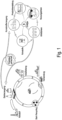
- Fig. 1:
- Nutzung der erfindungsgemäßen Schlacke in einer Kreislaufwirtschaft;
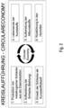
- Fig. 2:
- Einzelne Etappen einer Kreislaufwirtschaft;
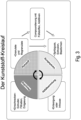
- Fig. 3:
- Kunststoffkreislauf;
- Fig. 4:
- Massenflussdiagramm;
- Fig. 5:
- Chemische Zusammensetzung der erfindungsgemäßen Hochofenschlacke.
- Die erfindungsgemäße Schlacke wird einer Kreislauwirtschaft zugeführt, indem sie als Füllstoff einem Kunststoff zugesetzt wird (
Figur 1 ). Der die Schlacke enthaltende Kunststoff wird für die Herstellung diverser Kunststofferzeugnisse verwendet. Dabei kann es sich beispielsweise um Haushaltsprodukte, Verpackungen, industrielle Bauteile, Kunststoffartikel für die Automobilindustrie o.ä. handeln. Durch den Zusatz der Schlacke werden die mechanischen Eigenschaften der jeweiligen Kunststofferzeugnisse und/oder die Lebensdauer verbessert. Hierbei kann es sich um eine Verbesserung der Härte, Festigkeit, Verarbeitbarkeit o.ä. handeln. - Nach der Herstellungsphase werden die Schlacke enthaltenden Kunststofferzeugnisse einer Nutzung zugeführt. Am Ende der Nutzungsphase erreichen die Kunststofferzeugnisse die Abfallphase, in der sie für eine Wiederverwertung aufbereitet werden. Anschließend werden sie einem Stahlherstellungskreislauf zugeführt.
- Im Hochofen werden der Kunststoff und die Schlacke thermisch voneinander getrennt. Der Kunststoff wird dem Stahlherstellungsprozess als Energieträger und/oder Reduktionsmittel zugeführt. Die Schlacke wird regeneriert und kann einem neuen Kreislauf zugeführt werden.
- Vor der Verwendung als mineralischer Füllstoff kann die Schlacke beispielsweise durch Mahlung aufbereitet werden (
Figur 2 ). Anschließend wird sie einem Kunststoffkreislauf als mineralischer Füllstoff zugeführt (Figur 3 ). Dabei wird ein Kunststoff-Rohstoff, z. B. ein Kunststoffgranulat, mit der Schlacke versetzt. Dieser Prozess wird als Compoundierung bezeichnet. - Die derart compoundierten Kunststoffgranulate werden einem oder mehreren Verarbeitungsschritten unterzogen, die zu einem fertiggestellten Kunststofferzeugnis führen. Dabei kann es sich um Prozesse, wie beispielsweise Spritzguss, Extrusion oder Blassformen handeln.
- Am Lebensende werden die Kunststofferzeugnisse entweder direkt entsorgt oder durch Recycling aufbereitet. Die Kunststoffaufbereitung kann solche Prozesse wie Einschnecken, Extrusion, Filtration oder Entgasung umfassen. Das Ziel einer derartigen Aufbereitung ist die Herstellung eines Kunststoffgranulats, das einer erneuten Compoundierung und Verarbeitung unterzogen werden kann.
- Nachfolgend wird auf die Massenströme während des gesamten Zyklusses näher eingegangen. Zunächst wird bei der Compoundierung ein s. g. Masterbatch erzeugt, hierzu werden ein Massenstromanteil von 80 eines Füllstoffes und ein Massenstromanteil von 20 eines Kunststoffes als Masterbatch mit dem Massenstromanteil 100 zusammengeführt (
Figur 4 ). - Der derart erzeugte Masterbatch wird als Basis für die Herstellung der späteren Kunststofferzeugnisse verwendet. Während der Herstellung kann noch zusätzlich Kunststoff, z. B. in der Höhe von 150 Massenanteilen, zugegeben werden. Das fertiggestellte Endprodukt kann somit 250 Massenanteile enthalten. Am Ende der Lebensdauer wird dementsprechend ein Massenstromanteil von 250 einem Hochofenprozess zugeführt. Im Hochofenprozess wird ein Massenstromanteil von 170 ausgeschleust in Form von dem Kunststoffanteil der thermisch verwertet wird. Es verbleibt ein Feststoffmassenstromanteil von 80 in Form von Hochofenschlacke aus dem Compound-Material. Dieser Feststoffmassenstromanteil wird in den Kreislauf zurückgeführt, in dem er wiederum mit einem Kunststoffanteil von 20 zu einem Masterbatch verarbeitet wird.
- Die Erfindung wird anhand eines Beispiels beispielhaft erläutert.
- Bei der erfindungsgemäßen Schlacke handelt es sich um eine Hochofenschlacke, die die folgende chemische Zusammensetzung aufweist:
SiOz 36,7% Al2O3 12,9% CaO 34,9% Mg0 10,5% Mn 0,8% Fe0 0,4% Feges. 0,4% TiOz 1,1% NazO 0,3% K2O 1,2% Sges.. 0,8% - Feges bezeichnet den gesamten Anteil an elementaren Eisen in jeglicher Form (mit Ausnahme von oxdischem Eisen, welches als FeO separat gekennzeichnet ist).
- Sges bezeichnet den gesamten Anteil an elementaren Schwefel.
- Die Hochofenschlacke wird im Schmelzfluss vom Metall abgetrennt und in flüssigem Zustand abgekühlt: entweder mit Wasser oder durch Abgießen. Erfindungsgemäß wird die abgekühlte Schlacke mittels eines Kugelmühl- und/oder Jetmühlprozesses fein gemahlen. 98 % der Partikel haben eine Korngröße unter 20 µm. Die Abrasivität ist hier deutlich minimiert.
- Die erfindungsgemäß hergestellte Hochofenschlacke wird im nächsten Schritt als mineralischer Füllstoff verwendet. Dafür wird sie mit einem bei Raumtemperatur festen Energieträger und/oder Reduktionsmittel, das in Pulverform vorliegt, vermengt. Dabei wird sie im Fall von Thermoplasten bevorzugt auf einer Doppelschnecken-Compoundinganlage in eine Polymerschmelze eindispergiert und abschließend zu einem üblichen Kunststoff-Granulat (ca. 3-5 mm Durchmesser) am Heißstrang oder über eine Unterwassergranulierung granuliert. Im Fall von Duromeren ist die direkte Einmischung und Dispergierung in Harze bei Raumtemperatur und unter Verwendung von Rührvorrichtungen, wie sie in der Lackindustrie üblich sind, möglich.
- Der dabei entstandene Verbundwerkstoff wird anderen Verarbeitungsschritten, die zu einem Formkörper führen, unterzogen. Im Regelfall handelt es sich hierbei um diskontinuierlichen Spritzguss oder eine kontinuierliche Extrusion. Der fertig geformte Formkörper wird in den Nutzungskreislauf eingeführt, am Lebensende eingesammelt und zum Schluss dem Hochofenprozess zugeführt. Im Hochofen wird der Verbundwerkstoff thermisch in die Hochofenschlacke und den Energieträger und/oder das Reduktionsmittel gespalten. Der Energieträger und/oder das Reduktionsmittel wird bei der Metallerzeugung verbraucht. Die Hochofenschlacke wird am Ende abgetrennt und einem neuen Kreislauf zugeführt.
Claims (20)
- Verfahren zur Kreislaufführung metallurgischer Schlacken, wobei eine in einem metallurgischen Prozess erzeugte Schlacke mit einem Energieträger und/oder Reduktionsmittel vermischt wird und dabei ein Verbundwerkstoff erzeugt wird, wobei der Verbundwerkstoff einer sekundären Nutzung zugeführt wird und am Lebensende in den entsprechenden metallurgischen Prozess zurückgeführt wird, wobei der Verbundwerkstoff einerseits Schlacke und andererseits Energie liefert und/oder reduzierend wirkt, wobei der Energieträger und/oder das Reduktionsmittel im metallurgischen Prozess verbraucht wird und die metallurgische Schlacke am Ende des Prozesses abgetrennt und einem neuen Kreislauf zugeführt wird, wobei der Energieträger und/oder das Reduktionsmittel eine polymere Verbindung auf Kohlenstoffbasis ist, z.B. ein Thermoplast, ein Duroplast und/oder ein Elastomer, wobei eine metallurgische Schlacke verwendet wird, die eine BET-Oberfläche von kleiner gleich 10 m2/g aufweist.
- Verfahren nach Anspruch 1, dadurch gekennzeichnet, dass die metallurgische Schlacke mit dem Energieträger und/oder Reduktionsmittel gemischt wird, wobei die metallurgische Schlacke eine Hochofenschlacke ist.
- Verfahren nach Anspruch 1, dadurch gekennzeichnet, dass die metallurgische Schlacke mit dem Energieträger und/oder Reduktionsmittel gemischt wird, wobei die metallurgische Schlacke eine Stahlwerkschlacke, insbesondere eine LD-Schlacke ist.
- Verfahren nach Anspruch 1, dadurch gekennzeichnet, dass die metallurgische Schlacke mit dem Energieträger und/oder Reduktionsmittel gemischt wird, wobei die metallurgische Schlacke eine Metallhüttenschlacke ist.
- Verfahren nach einem der vorhergehenden Ansprüche, dadurch gekennzeichnet, dass die metallurgische Schlacke gemahlen und/oder klassiert wird, um ein gewünschtes Kornband und/oder eine gewünschte Kornverteilung einzustellen.
- Verfahren nach Anspruch 5, dadurch gekennzeichnet, dass die metallurgische Schlacke gemahlen wird.
- Verfahren nach einem der vorhergehenden Ansprüche, dadurch gekennzeichnet, dass die metallurgische Schlacke nach der Feinmahlung einem Sichtungsprozess unterzogen wird, um ein definiertes Kornband einzustellen.
- Verfahren nach einem der vorhergehenden Ansprüche, dadurch gekennzeichnet, dass eine metallurgische Schlacke verwendet wird, die eine Partikelgröße von unter 20 µm aufweist.
- Verfahren nach einem der vorhergehenden Ansprüche, dadurch gekennzeichnet, dass eine metallurgische Schlacke verwendet wird, die die folgende chemische Zusammensetzung aufweist:
SiO2 28,0 - 45,0% Al2O3 6,0 - 17,0 % CaO 26,0 - 45,0 % MgO 7 - 12 % Mn 0,5 - 3,0 % FeO < 1,0 % Feges. < 1 % TiO2 < 1,8 % Na2O ≤ 0,6 % K2O ≤ 2,0 % Sges. < 1,5 % - Verfahren nach einem der vorhergehenden Ansprüche, dadurch gekennzeichnet, dass eine metallurgische Schlacke verwendet wird, die eine silanfreie und/oder kopplerfreie, insbesondere silankopplerfreie, Zusammensetzung hat.
- Verfahren nach Anspruch 10, dadurch gekennzeichnet, dass die metallurgische Schlacke mit dem Energieträger und/oder Reduktionsmittel gemischt wird, wobei der Energieträger und/oder das Reduktionsmittel formgebend ist.
- Verfahren nach Anspruch 11, dadurch gekennzeichnet, dass die metallurgische Schlacke als funktioneller Füllstoff mit einem Energieträger-Kunststoff compoundiert wird.
- Verfahren nach Anspruch 1, dadurch gekennzeichnet, dass der erzeugte Verbundwerkstoff zu einem Formkörper verarbeitet wird.
- Verfahren nach Anspruch 1, dadurch gekennzeichnet, dass der erzeugte Verbundwerkstoff bezüglich der verwendeten Schlacke gekennzeichnet wird.
- Verwendung eines mineralischen Füllstoffes in einem Verfahren nach einem der vorhergehenden Ansprüche, dadurch gekennzeichnet, dass
der Füllstoff eine metallurgische Schlacke ist, wobei die metallurgische Schlacke silanfrei und/oder kopplerfrei, insbesondere silankopplerfrei, ist und die folgende chemische Zusammensetzung hat:SiO2 28,0 - 45,0% Al2O3 6,0 - 17,0 % CaO 26,0 - 45,0 % MgO 7 - 12 % Mn 0,5 - 3,0 % FeO < 1,0 % Feges. < 1 % TiO2 < 1,8 % Na2O ≤ 0,6 % K2O ≤ 2,0 % Sges. < 1,5 % - Verwendung nach Anspruch 15, dadurch gekennzeichnet, dass die metallurgische Schlacke eine Hochofenschlacke ist.
- Verwendung nach Anspruch 15, dadurch gekennzeichnet, dass die metallurgische Schlacke eine Stahlwerkschlacke, insbesondere eine LD-Schlacke ist.
- Verwendung nach Anspruch 15, dadurch gekennzeichnet, dass die metallurgische Schlacke eine Metallhüttenschlacke ist.
- Verwendung nach Ansprüchen 15 bis 18, dadurch gekennzeichnet, dass die metallurgische Schlacke fein gemahlen und/oder klassiert ist und eine Partikelgröße von unter 20 µm aufweist.
- Verwendung nach einem der Ansprüche 15 bis 18, dadurch gekennzeichnet, dass die metallurgische Schlacke eine geringe Abrasivität von weniger als 20 mg gemäß Einlehner 1000 - Test aufweist.
Applications Claiming Priority (1)
| Application Number | Priority Date | Filing Date | Title |
|---|---|---|---|
| DE102020111459.1A DE102020111459A1 (de) | 2020-04-27 | 2020-04-27 | Verfahren zur Kreislaufführung metallurgischer Schlacken |
Publications (3)
| Publication Number | Publication Date |
|---|---|
| EP3904539A1 EP3904539A1 (de) | 2021-11-03 |
| EP3904539C0 EP3904539C0 (de) | 2023-07-19 |
| EP3904539B1 true EP3904539B1 (de) | 2023-07-19 |
Family
ID=75690168
Family Applications (1)
| Application Number | Title | Priority Date | Filing Date |
|---|---|---|---|
| EP21170615.5A Active EP3904539B1 (de) | 2020-04-27 | 2021-04-27 | Verfahren zur kreislaufführung metallurgischer schlacken und verwendung einer schlacke hierfür |
Country Status (4)
| Country | Link |
|---|---|
| EP (1) | EP3904539B1 (de) |
| DE (1) | DE102020111459A1 (de) |
| ES (1) | ES2952215T3 (de) |
| PL (1) | PL3904539T3 (de) |
Family Cites Families (10)
| Publication number | Priority date | Publication date | Assignee | Title |
|---|---|---|---|---|
| DE1912354B2 (de) | 1969-03-12 | 1972-04-13 | Reimbold & Strick, 5000 Köln-Kalk | Synthetisches kristallines calciumsilikat und verfahren zu seiner herstellung |
| DE2033592C3 (de) | 1970-07-07 | 1979-01-04 | Anton 8901 Anhausen Breunig | Abrasionstestgerät |
| DE3811392A1 (de) | 1988-04-05 | 1989-10-19 | Juergen Mennes | Mit fuellmittel gefuellter kunststoff |
| DE4104252C2 (de) | 1991-02-13 | 1998-07-02 | Schingnitz Manfred | Entsorgungsverfahren für schadstoffbelastete, kohlenstoffhaltige Abfallstoffe |
| US6179895B1 (en) * | 1996-12-11 | 2001-01-30 | Performix Technologies, Ltd. | Basic tundish flux composition for steelmaking processes |
| US20050257644A1 (en) * | 2000-09-14 | 2005-11-24 | Nkk Corporation | Refining agent and refining method |
| BRPI0611831A2 (pt) * | 2005-06-17 | 2010-09-28 | Ferrinov Inc | pigmentos anticorrosão derivados da poeira de um forno de arco voltaico e contendo cálcio sacrificial |
| DE102015014234A1 (de) | 2015-11-04 | 2017-05-04 | Helmut Aaslepp | Umweltfreundliches Hochofenverfahren zur Roheisenerzeugung mit Nutzung erneuerbarer Energien |
| BE1023884B1 (fr) * | 2016-07-08 | 2017-09-04 | Lhoist Rech Et Developpement Sa | Procédé de fabricatrion de briquettes contenant de l'oxyde de fer actif, et briquettes ainsi obtenues |
| CN109370044A (zh) | 2018-09-11 | 2019-02-22 | 上海宝田新型建材有限公司 | 一种矿渣微粉改性聚丙烯复合材料及其制备方法 |
-
2020
- 2020-04-27 DE DE102020111459.1A patent/DE102020111459A1/de active Pending
-
2021
- 2021-04-27 ES ES21170615T patent/ES2952215T3/es active Active
- 2021-04-27 EP EP21170615.5A patent/EP3904539B1/de active Active
- 2021-04-27 PL PL21170615.5T patent/PL3904539T3/pl unknown
Also Published As
| Publication number | Publication date |
|---|---|
| DE102020111459A1 (de) | 2021-10-28 |
| PL3904539T3 (pl) | 2023-10-02 |
| EP3904539C0 (de) | 2023-07-19 |
| EP3904539A1 (de) | 2021-11-03 |
| ES2952215T3 (es) | 2023-10-30 |
Similar Documents
| Publication | Publication Date | Title |
|---|---|---|
| EP2321437B1 (de) | Verfahren zur herstellung von agglomeraten aus feinkörnigen eisenträgern | |
| AT404735B (de) | Verfahren und anlage zur herstellung von flüssigem roheisen oder flüssigen stahlvorprodukten | |
| DE60129558T2 (de) | Herstellungsverfahren eines metallisierten briketts | |
| AT403055B (de) | Verfahren zur verwertung von eisenhältigen abfall- oder reststoffen | |
| EP2281071A1 (de) | Verfahren und vorrichtung zur herstellung von roheisen oder flüssigen stahlvorprodukten | |
| EP0302047B1 (de) | Verfahren und Anlage zur Gewinnung von flüssigem Roheisen oder Stahlvorprodukten aus stückigen, eisenoxidhältigen Einsatzstoffen | |
| AT516369A2 (de) | Flussmittel, Verfahren zu seiner Herstellung, Agglomerationsgemisch und Verwendung von Schlacke aus der Sekundärmetallurgie | |
| EP1721677A2 (de) | Verfahren zur Aufbereitung von Shredder-Rückständen und Verwendung einer erzeugten Sand-Fraktion | |
| DE102017212583A1 (de) | Pellet als Zuschlagstoff für metallurgische Prozesse und Verfahren zu dessen Herstellung und Verwendung | |
| AT405054B (de) | Verfahren und anlage zum herstellen einer eisenschmelze unter einsatz von eisenhältigen hüttenwerksreststoffen | |
| DE3223203C1 (de) | Verfahren und Anlage zur Herstellung bindemittelloser Heissbriketts | |
| EP0611740B1 (de) | Titanhaltiger Zuschlagstoff und dessen Verwendung zur Erhöhung der Haltbarkeit der feuerfesten Ausmauerung eines Ofens | |
| EP0622465B1 (de) | Verfahren zur Erzeugung von Metall aus Metallerzen | |
| DE102015011067B4 (de) | Verfahren zur Brikettierung pulverförmiger Legierungszuschläge der Stahl-, Gießerei- und NE-Metallurgie mit Hilfe faserhaltiger Strukturbildner und ein Brikett | |
| AT406272B (de) | Verfahren zur herstellung von direkt reduziertem eisen, flüssigem roheisen und stahl sowie anlage zur durchführung des verfahrens | |
| CN113981215B (zh) | 一种以城市污泥和冶金尘泥为原料制备烧结矿的方法 | |
| EP3904539A1 (de) | Verfahren zur kreislaufführung metallurgischer schlacken und verwendung einer schlacke hierfür | |
| DE69801157T2 (de) | Verfahren zum wiederverwerten von abfallstoffen der messinggiessereien | |
| DE19830102C1 (de) | Verwendung eines bei der Herstellung von Titandioxid anfallenden feinkörnigen Produkts | |
| AT407054B (de) | Verfahren zum herstellen von flüssigem roheisen | |
| DE2316883A1 (de) | Verfahren zur herstellung von metallischem eisen aus einem eisenoxid und ein ne-metalloxid enthaltenden material | |
| EP2662457A1 (de) | Verfahren und Vorrichtung zur Herstellung von Agglomeraten und Verwendung der Agglomerate in einem FINEX®-Verfahren | |
| WO1997033004A1 (de) | Verfahren zur herstellung von flüssigem roheisen oder flüssigen stahlvorprodukten und metallschwamm | |
| DE19520651A1 (de) | Verfahren zur Verwertung und Entsorgung von Klär- bzw. Wasserwerksschlämmen | |
| DE102012005454B4 (de) | Verfahren und Vorrichtung zur Herstellung von gehärteten Granalien aus eisenhaltigen Partikeln |
Legal Events
| Date | Code | Title | Description |
|---|---|---|---|
| PUAI | Public reference made under article 153(3) epc to a published international application that has entered the european phase |
Free format text: ORIGINAL CODE: 0009012 |
|
| STAA | Information on the status of an ep patent application or granted ep patent |
Free format text: STATUS: THE APPLICATION HAS BEEN PUBLISHED |
|
| AK | Designated contracting states |
Kind code of ref document: A1 Designated state(s): AL AT BE BG CH CY CZ DE DK EE ES FI FR GB GR HR HU IE IS IT LI LT LU LV MC MK MT NL NO PL PT RO RS SE SI SK SM TR |
|
| B565 | Issuance of search results under rule 164(2) epc |
Effective date: 20210726 |
|
| STAA | Information on the status of an ep patent application or granted ep patent |
Free format text: STATUS: REQUEST FOR EXAMINATION WAS MADE |
|
| 17P | Request for examination filed |
Effective date: 20220124 |
|
| RBV | Designated contracting states (corrected) |
Designated state(s): AL AT BE BG CH CY CZ DE DK EE ES FI FR GB GR HR HU IE IS IT LI LT LU LV MC MK MT NL NO PL PT RO RS SE SI SK SM TR |
|
| STAA | Information on the status of an ep patent application or granted ep patent |
Free format text: STATUS: EXAMINATION IS IN PROGRESS |
|
| 17Q | First examination report despatched |
Effective date: 20220401 |
|
| GRAP | Despatch of communication of intention to grant a patent |
Free format text: ORIGINAL CODE: EPIDOSNIGR1 |
|
| STAA | Information on the status of an ep patent application or granted ep patent |
Free format text: STATUS: GRANT OF PATENT IS INTENDED |
|
| INTG | Intention to grant announced |
Effective date: 20230213 |
|
| GRAS | Grant fee paid |
Free format text: ORIGINAL CODE: EPIDOSNIGR3 |
|
| GRAA | (expected) grant |
Free format text: ORIGINAL CODE: 0009210 |
|
| STAA | Information on the status of an ep patent application or granted ep patent |
Free format text: STATUS: THE PATENT HAS BEEN GRANTED |
|
| P01 | Opt-out of the competence of the unified patent court (upc) registered |
Effective date: 20230515 |
|
| AK | Designated contracting states |
Kind code of ref document: B1 Designated state(s): AL AT BE BG CH CY CZ DE DK EE ES FI FR GB GR HR HU IE IS IT LI LT LU LV MC MK MT NL NO PL PT RO RS SE SI SK SM TR |
|
| REG | Reference to a national code |
Ref country code: GB Ref legal event code: FG4D Free format text: NOT ENGLISH |
|
| REG | Reference to a national code |
Ref country code: CH Ref legal event code: EP |
|
| REG | Reference to a national code |
Ref country code: DE Ref legal event code: R096 Ref document number: 502021001026 Country of ref document: DE |
|
| REG | Reference to a national code |
Ref country code: IE Ref legal event code: FG4D Free format text: LANGUAGE OF EP DOCUMENT: GERMAN |
|
| P04 | Withdrawal of opt-out of the competence of the unified patent court (upc) registered |
Effective date: 20230801 |
|
| U01 | Request for unitary effect filed |
Effective date: 20230728 |
|
| U07 | Unitary effect registered |
Designated state(s): AT BE BG DE DK EE FI FR IT LT LU LV MT NL PT SE SI Effective date: 20230803 |
|
| REG | Reference to a national code |
Ref country code: ES Ref legal event code: FG2A Ref document number: 2952215 Country of ref document: ES Kind code of ref document: T3 Effective date: 20231030 |
|
| REG | Reference to a national code |
Ref country code: LT Ref legal event code: MG9D |
|
| PG25 | Lapsed in a contracting state [announced via postgrant information from national office to epo] |
Ref country code: GR Free format text: LAPSE BECAUSE OF FAILURE TO SUBMIT A TRANSLATION OF THE DESCRIPTION OR TO PAY THE FEE WITHIN THE PRESCRIBED TIME-LIMIT Effective date: 20231020 |
|
| PG25 | Lapsed in a contracting state [announced via postgrant information from national office to epo] |
Ref country code: IS Free format text: LAPSE BECAUSE OF FAILURE TO SUBMIT A TRANSLATION OF THE DESCRIPTION OR TO PAY THE FEE WITHIN THE PRESCRIBED TIME-LIMIT Effective date: 20231119 |
|
| PG25 | Lapsed in a contracting state [announced via postgrant information from national office to epo] |
Ref country code: RS Free format text: LAPSE BECAUSE OF FAILURE TO SUBMIT A TRANSLATION OF THE DESCRIPTION OR TO PAY THE FEE WITHIN THE PRESCRIBED TIME-LIMIT Effective date: 20230719 Ref country code: NO Free format text: LAPSE BECAUSE OF FAILURE TO SUBMIT A TRANSLATION OF THE DESCRIPTION OR TO PAY THE FEE WITHIN THE PRESCRIBED TIME-LIMIT Effective date: 20231019 Ref country code: IS Free format text: LAPSE BECAUSE OF FAILURE TO SUBMIT A TRANSLATION OF THE DESCRIPTION OR TO PAY THE FEE WITHIN THE PRESCRIBED TIME-LIMIT Effective date: 20231119 Ref country code: HR Free format text: LAPSE BECAUSE OF FAILURE TO SUBMIT A TRANSLATION OF THE DESCRIPTION OR TO PAY THE FEE WITHIN THE PRESCRIBED TIME-LIMIT Effective date: 20230719 Ref country code: GR Free format text: LAPSE BECAUSE OF FAILURE TO SUBMIT A TRANSLATION OF THE DESCRIPTION OR TO PAY THE FEE WITHIN THE PRESCRIBED TIME-LIMIT Effective date: 20231020 |
|
| REG | Reference to a national code |
Ref country code: DE Ref legal event code: R097 Ref document number: 502021001026 Country of ref document: DE |
|
| PG25 | Lapsed in a contracting state [announced via postgrant information from national office to epo] |
Ref country code: SM Free format text: LAPSE BECAUSE OF FAILURE TO SUBMIT A TRANSLATION OF THE DESCRIPTION OR TO PAY THE FEE WITHIN THE PRESCRIBED TIME-LIMIT Effective date: 20230719 Ref country code: RO Free format text: LAPSE BECAUSE OF FAILURE TO SUBMIT A TRANSLATION OF THE DESCRIPTION OR TO PAY THE FEE WITHIN THE PRESCRIBED TIME-LIMIT Effective date: 20230719 Ref country code: SK Free format text: LAPSE BECAUSE OF FAILURE TO SUBMIT A TRANSLATION OF THE DESCRIPTION OR TO PAY THE FEE WITHIN THE PRESCRIBED TIME-LIMIT Effective date: 20230719 |
|
| PLBE | No opposition filed within time limit |
Free format text: ORIGINAL CODE: 0009261 |
|
| STAA | Information on the status of an ep patent application or granted ep patent |
Free format text: STATUS: NO OPPOSITION FILED WITHIN TIME LIMIT |
|
| U20 | Renewal fee for the european patent with unitary effect paid |
Year of fee payment: 4 Effective date: 20240429 |
|
| 26N | No opposition filed |
Effective date: 20240422 |
|
| U1N | Appointed representative for the unitary patent procedure changed after the registration of the unitary effect |
Representative=s name: WSL PATENTANWAELTE PARTNERSCHAFT MBB; DE |
|
| PG25 | Lapsed in a contracting state [announced via postgrant information from national office to epo] |
Ref country code: MC Free format text: LAPSE BECAUSE OF FAILURE TO SUBMIT A TRANSLATION OF THE DESCRIPTION OR TO PAY THE FEE WITHIN THE PRESCRIBED TIME-LIMIT Effective date: 20230719 |
|
| PG25 | Lapsed in a contracting state [announced via postgrant information from national office to epo] |
Ref country code: MC Free format text: LAPSE BECAUSE OF FAILURE TO SUBMIT A TRANSLATION OF THE DESCRIPTION OR TO PAY THE FEE WITHIN THE PRESCRIBED TIME-LIMIT Effective date: 20230719 |
|
| REG | Reference to a national code |
Ref country code: CH Ref legal event code: PL |
|
| P05 | Withdrawal of opt-out of the competence of the unified patent court (upc) changed |
Free format text: CASE NUMBER: APP_557721/2023 Effective date: 20230803 |
|
| PG25 | Lapsed in a contracting state [announced via postgrant information from national office to epo] |
Ref country code: CH Free format text: LAPSE BECAUSE OF NON-PAYMENT OF DUE FEES Effective date: 20240430 |
|
| PG25 | Lapsed in a contracting state [announced via postgrant information from national office to epo] |
Ref country code: IE Free format text: LAPSE BECAUSE OF NON-PAYMENT OF DUE FEES Effective date: 20240427 |
|
| U20 | Renewal fee for the european patent with unitary effect paid |
Year of fee payment: 5 Effective date: 20250428 |
|
| PGFP | Annual fee paid to national office [announced via postgrant information from national office to epo] |
Ref country code: PL Payment date: 20250408 Year of fee payment: 5 |
|
| PGFP | Annual fee paid to national office [announced via postgrant information from national office to epo] |
Ref country code: GB Payment date: 20250428 Year of fee payment: 5 Ref country code: ES Payment date: 20250505 Year of fee payment: 5 |
|
| PGFP | Annual fee paid to national office [announced via postgrant information from national office to epo] |
Ref country code: CZ Payment date: 20250408 Year of fee payment: 5 |
|
| PG25 | Lapsed in a contracting state [announced via postgrant information from national office to epo] |
Ref country code: CY Free format text: LAPSE BECAUSE OF FAILURE TO SUBMIT A TRANSLATION OF THE DESCRIPTION OR TO PAY THE FEE WITHIN THE PRESCRIBED TIME-LIMIT; INVALID AB INITIO Effective date: 20210427 |
|
| PG25 | Lapsed in a contracting state [announced via postgrant information from national office to epo] |
Ref country code: HU Free format text: LAPSE BECAUSE OF FAILURE TO SUBMIT A TRANSLATION OF THE DESCRIPTION OR TO PAY THE FEE WITHIN THE PRESCRIBED TIME-LIMIT; INVALID AB INITIO Effective date: 20210427 |