EP3904009A1 - Agrafeuse électrique, dispositif de post-traitement, et système de formation d'images - Google Patents
Agrafeuse électrique, dispositif de post-traitement, et système de formation d'images Download PDFInfo
- Publication number
- EP3904009A1 EP3904009A1 EP21170706.2A EP21170706A EP3904009A1 EP 3904009 A1 EP3904009 A1 EP 3904009A1 EP 21170706 A EP21170706 A EP 21170706A EP 3904009 A1 EP3904009 A1 EP 3904009A1
- Authority
- EP
- European Patent Office
- Prior art keywords
- motor
- electric stapler
- rotation amount
- paper bundle
- stop target
- Prior art date
- Legal status (The legal status is an assumption and is not a legal conclusion. Google has not performed a legal analysis and makes no representation as to the accuracy of the status listed.)
- Pending
Links
Images


Classifications
-
- B—PERFORMING OPERATIONS; TRANSPORTING
- B25—HAND TOOLS; PORTABLE POWER-DRIVEN TOOLS; MANIPULATORS
- B25C—HAND-HELD NAILING OR STAPLING TOOLS; MANUALLY OPERATED PORTABLE STAPLING TOOLS
- B25C5/00—Manually operated portable stapling tools; Hand-held power-operated stapling tools; Staple feeding devices therefor
- B25C5/10—Driving means
- B25C5/15—Driving means operated by electric power
-
- B—PERFORMING OPERATIONS; TRANSPORTING
- B27—WORKING OR PRESERVING WOOD OR SIMILAR MATERIAL; NAILING OR STAPLING MACHINES IN GENERAL
- B27F—DOVETAILED WORK; TENONS; SLOTTING MACHINES FOR WOOD OR SIMILAR MATERIAL; NAILING OR STAPLING MACHINES
- B27F7/00—Nailing or stapling; Nailed or stapled work
- B27F7/17—Stapling machines
- B27F7/30—Driving means
- B27F7/36—Driving means operated by electric power
-
- B—PERFORMING OPERATIONS; TRANSPORTING
- B27—WORKING OR PRESERVING WOOD OR SIMILAR MATERIAL; NAILING OR STAPLING MACHINES IN GENERAL
- B27F—DOVETAILED WORK; TENONS; SLOTTING MACHINES FOR WOOD OR SIMILAR MATERIAL; NAILING OR STAPLING MACHINES
- B27F7/00—Nailing or stapling; Nailed or stapled work
- B27F7/17—Stapling machines
- B27F7/19—Stapling machines with provision for bending the ends of the staples on to the work
Definitions
- the present invention relates to an electric stapler that binds a paper bundle with a staple, a post-processing device on which the electric stapler is mounted, and an image forming system including the post-processing device.
- the post-processing device may be equipped with an electric stapler that binds a paper bundle with a staple.
- striking capability varies depending on a rotation start position of a motor at the start of binding processing. For example, when the rotation start position of the motor at the start of the binding processing passes a desired rotation start position, a driver that drives a staple may be close to the paper bundle and the motor may not be accelerated until the staple reaches the paper bundle.
- a rotational position of the motor is acquired by detecting a rotational position of a gear driven by the motor with a home position sensor, and when it is detected that the motor or the gear reaches a predetermined rotational position, braking is started, and the motor and the gear are controlled to stop at a desired rotational position.
- a position at which the motor is actually stopped is not constant due to disturbance caused by variation in a power supply voltage, a motor characteristic, the number of sheets of paper, paper quality, an external environment such as temperature and humidity, and variation in a mechanical load or the like.
- Patent Literature 1 discloses a technique in which a motor (gear) is decelerated from a state in which a rotational position of the motor is before a detection position of a home position sensor, and the motor is stopped after being decelerated, so that the motor is stopped at a desired rotation stop position.
- Patent Literature 1 Japanese Patent No. 5428515
- an electric stapler including a clamp part that clamps a paper bundle, a penetration part that causes a staple to penetrate the paper bundle, a clinch part that bends the staple penetrating the paper bundle to bind the paper bundle, and a motor that drives the clamp part, the penetration part, and the clinch part, and performing binding processing accompanying rotation of the motor by sequentially performing a clamping process of clamping the paper bundle with the clinch part, a penetrating process of causing the staple to penetrate the paper bundle with the penetration part, and a clinching process of bending the staple penetrating the paper bundle with the clinch part, includes: a first position detection unit that detects that a rotational position of the motor passes a first position; a braking unit that applies braking to the motor after it is detected that the motor passes the first position; a difference calculation unit that calculates a difference between a position at which the motor is stopped by the braking unit and a predetermined stop target position of the motor;
- a difference between a position at which the motor is stopped and a predetermined stop target position of the motor is calculated, and the motor is rotated forward or in reverse by the calculated difference, whereby the stop position of the motor is adjusted to the stop target position.
- An electric stapler including a clamp part that clamps a paper bundle, a penetration part that causes a staple to penetrate the paper bundle, a clinch part that bends the staple penetrating the paper bundle to bind the paper bundle, and a motor that drives the clamp part, the penetration part, and the clinch part, and performing binding processing accompanying rotation of the motor by sequentially performing a clamping process of clamping the paper bundle with the clinch part, a penetrating process of causing the staple to penetrate the paper bundle with the penetration part, and a clinching process of bending the staple penetrating the paper bundle with the clinch part, includes: a first position detection unit that detects that a rotational position of the motor passes a first position; a deceleration unit that reduces a rotational speed of the motor after it is detected that the motor passes the first position; a rotation amount detection unit that detects a rotation amount of the motor since a start of deceleration of the motor; and a braking unit that applies braking to
- Fig. 1 is a side sectional view illustrating an example of an electric stapler according to an embodiment.
- An electric stapler 1A includes a clamp part 2 that clamps a paper bundle P, a penetration part 3 that causes a staple 10 to penetrate the paper bundle P, and a clinch part 4 that bends the staple 10 penetrating the paper bundle P to bind the paper bundle P.
- the electric stapler 1A includes a motor 5 that drives the clamp part 2, the penetration part 3, and the clinch part 4.
- the electric stapler 1A includes a striking unit 30 in which the penetration part 3 is provided, and a binding unit 40 in which the clinch part 4 is provided.
- the clamp part 2 includes a first wall portion 21 and a second wall portion 22 that face each other with a predetermined gap therebetween.
- the first wall portion 21 is formed at a portion facing the striking unit 30 of the binding unit 40.
- the second wall portion 22 is formed at a portion facing the binding unit 40 of the striking unit 30.
- the binding unit 40 moves in directions of approaching and separating from the striking unit 30 by a rotating operation with a shaft 31 serving as a fulcrum.
- the first wall portion 21 moves in directions of approaching and separating from the second wall portion 22.
- the clamp part 2 sandwiches the paper bundle P between the first wall portion 21 and the second wall portion 22 when the first wall portion 21 is moved in a direction of approaching the second wall portion 22.
- the paper bundle P sandwiched between the first wall portion 21 and the second wall portion 22 is released.
- a cartridge 100 in which the staples 10 are accommodated in a connected state, is detachably attached to the striking unit 30.
- the penetration part 3 separates one leading staple of the staples 10 accommodated in the cartridge 100, and strikes the staple 10 toward the paper bundle P sandwiched between the first wall portion 21 and the second wall portion 22 to penetrate the paper bundle P.
- the penetration part 3 may include a movable part movable between a first position and a second position. The second position is apart from the first position in the direction orthogonal to a surface of the paper bundle.
- the striking unit 30 includes a mechanism that feeds the staple 10 accommodated in the cartridge 100 to a position where the staple 10 can be struck by the penetration part 3.
- the striking unit 30 includes a mechanism that forms the staple 10 into a U shape, with the staples in a form of being connected in a sheet shape and accommodated in the cartridge 100 for supply.
- the clinch part 4 bends the staple 10 penetrating the paper bundle P sandwiched between the first wall portion 21 and the second wall portion 22 in a predetermined direction.
- the binding unit 40 may include a mechanism that cuts legs of the staple 10 penetrating the paper bundle P.
- the clinch part 4 may include a contact surface which comes into contact with the staple 10 to bend the staple 10.
- Fig. 2 is a side sectional view illustrating an example of a driving unit.
- the electric stapler 1A includes a driving unit 50 that transmits rotation of the motor 5 to the clamp part 2, the penetration part 3, and the clinch part 4.
- the driving unit 50 includes a driven gear 51 that transmits the rotation of the motor 5 to the clamp part 2, the penetration part 3, and the clinch part 4, and an intermediate gear 52 that transmits the rotation of the motor 5 to the driven gear 51.
- the driving unit 50 rotation of a motor shaft 5a of the motor 5 is transmitted to the driven gear 51 via the intermediate gear 52, and the driven gear 51 rotates.
- the driving unit 50 moves the binding unit 40 in directions of approaching and separating from the striking unit 30, and opens and closes the clamp part 2.
- the driving unit 50 drives the penetration part 3 and the clinch part 4 by transmitting the rotation of the driven gear 51 to a cam or the like (not illustrated).
- the binding unit 40 moves in a direction of approaching the striking unit 30, and the paper bundle P is clamped by the clamp part 2.
- the staples 10 accommodated in the cartridge 100 are fed out, and one leading staple 10 of the fed-out staples 10 is struck by the penetration part 3 toward the paper bundle P clamped by the clamp part 2 to penetrate the paper bundle P.
- the staple 10 penetrating the paper bundle P is bent by the clinch part 4.
- the binding unit 40 moves in a direction of separating from the striking unit 30, and clamping of the paper bundle P by the clamp part 2 is released.
- the electric stapler 1A performs a clamping process of clamping the paper bundle P with the clamp part 2, a penetrating process of striking the staple 10 into the paper bundle P with the penetration part 3, a clinching process of bending the staple 10 with the clinch part 4, and a returning process of releasing the paper bundle P clamped by the clamp part 2.
- a position along a rotation direction of the motor shaft 5a of the motor 5 is referred to as a rotational position of the motor 5.
- a position along a rotation direction of the driven gear 51 is referred to as a rotational position of the driven gear 51.
- the driven gear 51 meshes with the intermediate gear 52 and the intermediate gear 52 meshes with a gear (not illustrated) of the motor shaft 5a, and thus a rotational speed of the driven gear 51 is a value obtained by reducing a rotational speed of the motor 5 at a predetermined reduction ratio. Accordingly, a rotational position and a rotation amount of the driven gear 51 are proportional to a rotational position and a rotation amount of the motor 5.
- a home position sensor 101 (first position detection unit / first position detector) that detects a predetermined rotational position of the driven gear 51 is provided for the rotational positions of the motor 5 and the driven gear 51.
- the rotation amount of the motor 5 is detected based on an output of a magnetic sensor 102 (rotation amount detection unit) used for detecting a position of a rotor (not illustrated) of the motor 5 that is configured with a brushless motor.
- the home position sensor 101 detects the rotational position of the driven gear 51 in order to cause the clamp part 2, the penetration part 3, and the clinch part 4 to standby at a predetermined home position.
- a stop target range SE is set to a predetermined range in a circumferential direction of the driven gear 51 in order to stop the rotational position of the driven gear 51 at a predetermined position when stopping driving of the motor 5.
- the electric stapler 1A is configured such that an output of the home position sensor 101 changes from 0 (OFF) to 1 (ON), for example, when a stop target range start-point position PS (first position), which is a start-point of the stop target range SE, reaches a detection position P101 of the home position sensor 101 with respect to rotation of the driven gear 51 in a forward direction indicated by an arrow F.
- the electric stapler 1A is configured such that the output of the home position sensor 101 changes from 1 (ON) to 0 (OFF), for example, when a stop target range end-point position PE, which is an end-point of the stop target range SE, reaches the detection position P101 of the home position sensor 101 with respect to the rotation of the driven gear 51 in the forward direction indicated by the arrow F.
- the electric stapler 1A is configured such that the home position sensor 101 can detect the stop target range SE of the driven gear 51.
- a stop target position P1 of the driven gear 51 is set within the stop target range SE, and in this example, the stop target position P1 is almost set at a central position of the stop target range SE as illustrated in Fig. 2 .
- the stop target position P1 of the driven gear 51 is located at the detection position P101 of the home position sensor 101, the clamp part 2, the penetration part 3, and the clinch part 4 are located at respective home positions.
- the stop target range end-point position PE reaches the detection position P101 of the home position sensor 101.
- a predetermined range from the stop target range end-point position PE is set as a clamp range CL in which clamping of the paper bundle P by the clamp part 2 is performed in the clamping process.
- a penetration range TH is set in which the staple 10 is struck into the paper bundle P by the penetration part 3 in the penetrating process.
- a clinch range of the clinching process is set, and following the clinch range, a clamp release range of the returning process is set, met by the stop target range start-point position PS.
- Fig. 3 is a block diagram illustrating an example of control functions of the stapler.
- the electric stapler 1A includes a control unit (controller) 110 that controls the motor 5 and a motor driving unit (motor driving circuit) 111 that drives the motor 5.
- control unit controller 110 that controls the motor 5
- motor driving unit motor driving circuit
- the control unit 110 (implementing a braking unit, a difference calculation unit, a motor control unit, and a deceleration unit) includes a CPU 110a, and executes a program stored in a storage unit 110b to perform the binding processing of the electric stapler 1A.
- the motor driving unit 111 drives the motor 5 by known PWM control based on position information of a rotor (not illustrated) output from the magnetic sensor 102.
- the control unit 110 controls the stop position of the motor 5 based on the rotational position of the driven gear 51 detected by the home position sensor (HP sensor) 101 and based on the rotation amount of the motor 5 detected by the magnetic sensor 102, that is, the rotation amount of the driven gear 51.
- FIG. 4 is a configuration diagram illustrating an overview of an image forming system according to the present embodiment.
- An image forming system 500A of the present embodiment includes an image forming device 501A and a post-processing device 502A that is capable of performing at least one type of processing.
- the image forming device 501A forms and outputs an image on a sheet of paper fed from a paper feeding portion (not illustrated) inside or outside the device.
- the image forming device 501A forms an image on a sheet of paper by forming an electrostatic latent image by scanning exposure, developing the electrostatic latent image with toner, transferring the toner to the sheet of paper, and fixing the toner.
- the post-processing device 502A includes the above-described electric stapler 1A in a binding part 503A.
- the CPU 110a of the control unit 110 illustrated in Fig. 3 is connected to a control unit (not illustrated) of the post-processing device 502A and a control unit (not illustrated) of the image forming device 501A.
- Fig. 5A is a time chart illustrating a first operation example of the electric stapler according to the present embodiment
- Fig. 5B is a flowchart illustrating the first operation example of the electric stapler according to the present embodiment.
- the control unit 110 performs a clamping process of clamping the paper bundle P by the clamp part 2, a penetrating process of striking the staple 10 into the paper bundle P by the penetration part 3, a clinching process of bending the staple 10 by the clinch part 4, and a returning process of releasing the paper bundle P clamped by the clamp part 2.
- the control unit 110 When HP sensor ON is detected at (1) in Fig. 5A , that is, when the home position sensor 101 detects the stop target range start-point position PS of the driven gear 51 in step SA1 in Fig. 5B , the control unit 110 performs braking control of stopping the driving of the motor 5 in step SA2 in Fig. 5B .
- This braking control is also referred to as braking or applying a brake.
- the rotational position and the rotation amount of the driven gear 51 are proportional to the rotational position and the rotation amount of the motor 5.
- the home position sensor 101 detecting the stop target range start-point position PS of the driven gear 51 is equivalent to detecting that the rotational position of the motor 5 passes the first position.
- the control unit 110 acquires rotation amount information D1 based on position information output from the magnetic sensor 102 in step SA3 in Fig. 5B .
- the rotation amount information D1 is the number of pulses.
- the rotation amount of the motor 5 from when the home position sensor 101 detects the stop target range start-point position PS of the driven gear 51 to when the stop target position P1 of the driven gear 51 reaches the detection position P101 of the home position sensor 101 is determined. Then, the stop target position P1 is set at a position separated from the stop target range start-point position PS by a first distance (corresponding to 3 pulses in this example (illustrated example)).
- the rotation amount of the motor 5 from the detection of the stop target range start-point position PS of the driven gear 51 to the arrival of the stop target position P1 of the driven gear 51 at the detection position P101 of the home position sensor 101 is referred to as a stop rotation amount D2.
- the control unit 110 compares the rotation amount information D1 (6 pulses in the illustrated example), which is counted in the count section of the magnetic sensor pulse during the braking (2) of Fig. 5A since the detection of the HP sensor ON at (1) in Fig. 5A , with the stop rotation amount D2 (3 pulses), and calculates a difference (3 pulses) between D1 and D2.
- the control unit 110 determines in step SA6 of Fig. 5B that the stop target position P1 of the driven gear 51 passes the detection position P101 of the home position sensor 101 (exceeding 3 pulses in the illustrated example).
- the calculation of the difference by comparing the rotation amount information D1 counted in the count section of the magnetic sensor pulse during the braking with the stop rotation amount D2 since the detection of the HP sensor ON is equivalent to calculation of a difference between a position at which the motor 5 is stopped and a predetermined stop target position of the motor 5.
- the stop target position P1 of the driven gear 51 passing the detection position P101 of the home position sensor 101 is equivalent to the stop positions of the driven gear 51 and the motor 5 being located downstream of the stop target position.
- the control unit 110 causes the motor 5 to rotate in reverse at a predetermined low speed in step SA7 of Fig. 5B .
- the motor 5 is rotated in reverse by 3 pulses.
- the low speed refers to a low speed with respect to the forward rotation of the motor 5 at the time of performing the clamping process, the penetrating process, and the clinching process.
- the control unit 110 acquires rotation amount information D3 based on the position information output from the magnetic sensor 102 in a count section of the magnetic sensor pulse during the reverse rotation of the motor 5 in (5) of Fig. 5A from the start of the low-speed reverse rotation of the motor 5 at (4) of Fig. 5A .
- the control unit 110 stops the low-speed reverse rotation of the motor 5 as illustrated at (6) in Fig. 5A .
- the stop target position P1 of the driven gear 51 is located at the detection position P101 of the home position sensor 101, and the rotation of the motor 5 is stopped.
- step SA8 of Fig. 5B When it is determined in step SA8 of Fig. 5B that the stop target position P1 of the driven gear 51 doses not reach the detection position P101 of the home position sensor 101, the control unit 110 causes the motor 5 to rotate forward at a predetermined low speed in step SA9 of Fig. 5B .
- the control unit 110 stops the low-speed forward rotation of the motor 5.
- the stop target position P1 of the driven gear 51 not reaching the detection position P101 of the home position sensor 101 is equivalent to the stop positions of the driven gear 51 and the motor 5 being located upstream of the stop target position.
- step SA10 of Fig. 5B when the stop target position P1 of the driven gear 51 is at the detection position P101 of the home position sensor 101, that is, when the rotational position (stop position) of the motor 5 is at the stop target position, the low-speed forward rotation or the low-speed reverse rotation of the motor 5 is not performed, and a stopped state is maintained.
- the driven gear 51 when the stop target position P1 of the driven gear 51 goes beyond (passes) the detection position P101 of the home position sensor 101 and stops, the driven gear 51 is moved backward (rotated in reverse) by an amount corresponding to an excess, and when the stop target position P1 is short of (does not reach) the detection position P101 and stops, the driven gear 51 is moved forward (rotated forward) by an amount corresponding to a shortfall, so that the stop target position P1 can be located at the detection position P101 that is a desired stop position. As described, the braking is applied to the motor 5 before reaching the detection position P101 (stop target range start-point position (first position) PS).
- Fig. 6A is a time chart illustrating a second operation example of the electric stapler according to the present embodiment
- Fig. 6B is a flowchart illustrating the second operation example of the electric stapler according to the present embodiment.
- the control unit 110 performs a clamping process, a penetrating process, a clinching process and the like.
- the control unit 110 performs braking control of stopping driving of the motor 5 in step SB2 of Fig. 6B . That is, after the stop target range start-point position PS of the driven gear 51 is detected and the home position sensor 101 is turned ON, the control unit 110 applies braking to the motor 5 during an ON-OFF section of the home position sensor 101.
- step SB3 of Fig. 6B the control unit 110 acquires the rotation amount information D1 based on position information output from the magnetic sensor 102, in a count section of a magnetic sensor pulse during braking of (2) of Fig. 6A after a period from the detection of the HP sensor ON at (0) of Fig. 6A to the detection of the HP sensor OFF at (1) of Fig. 6A .
- the control unit 110 determines that the motor 5 is stopped in step SB4 of Fig. 6B in stop determination time (3) of Fig. 6A , the control unit 110 compares the rotation amount information D1 counted in the count section of the magnetic sensor pulse during the braking of (2) of Fig. 6A with the stop rotation amount D2 since the detection of the HP sensor ON at (0) of Fig. 6A , and calculates a difference between D1 and D2 in step SB5 of Fig. 6B .
- the rotation amount information D1 is 9 pulses (6 pulses + 3 pulses) and exceeds the stop rotation amount D2 (3 pulses), and the stop target position P1 of the driven gear 51 goes beyond the detection position P101 of the home position sensor 101.
- the calculation of the difference by comparing the rotation amount information D1 counted in the count section of the magnetic sensor pulse during the braking with the stop rotation amount D2 since the detection of the HP sensor ON, is equivalent to calculation of a difference between a position at which the motor 5 is stopped and a predetermined stop target position of the motor 5.
- the stop target position P1 of the driven gear 51 going beyond the detection position P101 of the home position sensor 101 is equivalent to the stop positions of the driven gear 51 and the motor 5 being located downstream of the stop target position.
- the calculation of the difference between the position at which the motor 5 is stopped and the predetermined stop target position of the motor 5 is equivalent to calculation of a difference between a rotation amount of the motor 5 and a first distance.
- the control unit 110 When it is determined that the stop target position P1 of the driven gear 51 goes beyond the detection position P101 of the home position sensor 101, the control unit 110 causes the motor 5 to rotate in reverse at a predetermined low speed in step SB6 of Fig. 6B .
- the control unit 110 acquires rotation amount information D3 based on the position information output from the magnetic sensor 102 in a count section of the magnetic sensor pulse during the reverse rotation of the motor 5 in (5) of Fig. 6A from the start of the low-speed reverse rotation of the motor 5 at (4) of Fig. 6A .
- the control unit 110 stops the low-speed reverse rotation of the motor 5 correspondingly to the stop (6) of Fig. 6A .
- the rotation amount information D3 is 6 pulses
- the rotation amount information D3 matches the difference (6 pulses) between the rotation amount information D1 (9 pulses) and the stop rotation amount D2 (3 pulses), and thus the motor 5 is stopped after being rotated in reverse at the low speed by 6 pulses.
- the stop target position P1 of the driven gear 51 is located at the detection position P101 of the home position sensor 101, and the rotation of the motor 5 is stopped. Stopping the low-speed reverse rotation of the motor 5 when the rotation amount information D3 counted in the count section of the magnetic sensor pulse during the reverse rotation of the motor 5 matches the difference between the rotation amount information D1 and the stop rotation amount D2, is equivalent to moving the rotational position of the motor 5 to the stop target position by rotating the motor 5 in reverse by the calculated difference.
- Fig. 7A is a time chart illustrating a third operation example of the electric stapler according to the present embodiment
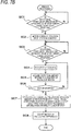
- Fig. 7B is a flowchart illustrating the third operation example of the electric stapler according to the present embodiment.
- the control unit 110 performs a clamping process, a penetrating process, a clinching process and the like.
- the control unit 110 causes the motor 5 to decelerate from the predetermined high-speed rotation in step SC2 of Fig. 7B , and causes the motor 5 to rotate forward over a predetermined time (time from ON of the home position sensor to OFF thereof), for a predetermined distance (distance covered during the time from ON of the home position sensor to OFF thereof) at a predetermined low speed.
- the low speed refers to a low speed with respect to the forward rotation of the motor 5 at the time of performing the clamping process, the penetrating process, and the clinching process.
- the control unit 110 performs braking control of stopping the driving of the motor 5 in step SC4 of Fig. 7B .
- the control unit 110 acquires the rotation amount information D1 based on position information output from the magnetic sensor 102 in step SC5 of Fig. 7B .
- the control unit 110 compares the rotation amount information D1 counted in the count section of the magnetic sensor pulse during the braking of (3) in Fig. 7A with the stop rotation amount D2 from the detection of the HP sensor ON at (1) of Fig. 7A , and calculates a difference between D1 and D2 in step SC5 of Fig. 7B .
- the rotation amount information D1 (8 pulses (6 pulses + 2 pulses)) exceeds the stop rotation amount D2 (3 pulses), and the stop target position P1 of the driven gear 51 goes beyond the detection position P101 of the home position sensor 101.
- the control unit 110 When it is determined that the stop target position P1 of the driven gear 51 goes beyond the detection position P101 of the home position sensor 101, the control unit 110 causes the motor 5 to rotate in reverse at a predetermined low speed in step SC8 of Fig. 7B .
- the control unit 110 acquires the rotation amount information D3 based on the position information output from the magnetic sensor 102 in a count section of the magnetic sensor pulse during the reverse rotation of the motor 5 in (6) of Fig. 7A from the start of the low-speed reverse rotation of the motor 5 at (5) of Fig. 7A .
- the control unit 110 stops the low-speed reverse rotation of the motor 5 corresponding to stop at (7) of Fig. 7A .
- the rotation amount information D3 is 5 pulses
- the rotation amount information D3 matches the difference (5 pulses) between the rotation amount information D1 (8 pulses) and the stop rotation amount D2 (3 pulses), and thus the low-speed reverse rotation of the motor 5 is stopped.
- the stop target position P1 of the driven gear 51 is located at the detection position P101 of the home position sensor 101, and the rotation of the motor 5 is stopped.
- the stop target range start-point position PS of the driven gear 51 is detected, a difference (5 pulses) between a distance (8 pulses) covering from the start of deceleration of the motor 5 to the stop of the motor 5 and a distance (the first distance, being 3 pulses in this example) from the stop target range start-point position PS to the stop target position P1 is calculated, and then the motor 5 is rotated in reverse by a distance corresponding to the difference.
- the stop target position P1 of the driven gear 51 is located at the detection position P101 of the home position sensor 101.
- Fig. 8 is a side sectional view illustrating an example of a driving unit according to another embodiment of the electric stapler.
- the stop target position P1 of the driven gear 51 is set on a front side with respect to rotation of the driven gear 51 in a forward direction indicated by the arrow F, from an intermediate position between the stop target range start-point position PS and the stop target range end-point position PE in the stop target range SE.
- a predetermined range from the stop target range end-point position PE is set as an idle feeding range EC, and following the idle feeding range EC are the clamp range CL and the penetration range TH.
- Fig. 9A is a time chart illustrating an operation example of the stapler according to the other embodiment
- Fig. 9B is a flowchart illustrating the operation example of the electric stapler according to the other embodiment.
- the control unit 110 performs a clamping process, a penetrating process, a clinching process and the like.
- the control unit 110 decelerates the motor 5 from the predetermined high-speed rotation to rotate forward at a predetermined low speed in step SD2 of Fig. 9B .
- Rotating the motor 5 forward at a low speed when the stop target range start-point position PS of the driven gear 51 is detected is equivalent to reducing a rotational speed of the motor 5 after it is detected that a rotational position of the motor 5 passes a first position.
- a rotation amount of the motor 5 from when the home position sensor 101 detects the stop target range start-point position PS of the driven gear 51 to when the stop target position P1 of the driven gear 51 reaches the detection position P101 of the home position sensor 101 is referred to as a stop rotation amount D5.
- the control unit 110 acquires the rotation amount information D1 based on position information output from the magnetic sensor 102 in step SD3 in Fig. 9B .
- Stopping the low-speed forward rotation of the motor 5 when the rotation amount information D1 counted during the low-speed forward rotation of the motor 5 from the detection of the HP sensor ON reaches the stop rotation amount D5, is equivalent to applying braking to the motor 5 when it is detected that the rotation amount of the motor 5 from the start of deceleration of the motor 5 reaches a predetermined value.
- the stop target position P1 of the driven gear 51 is located at the detection position P101 of the home position sensor 101, and the rotation of the motor 5 is stopped.
- 1A electric stapler 2 clamp part; 21 first wall portion; 22 second wall portion; 3 penetration part; 4 clinch part; 5 motor; 51 driven gear; 101 home position sensor (first position detection unit); 102 magnetic sensor (rotation amount detection unit); 110 control unit (braking unit, difference calculation unit, motor control unit, deceleration unit); SE stop target range; PS stop target range start-point position (first position); PE stop target range end-point position; P1 stop target position
Landscapes
- Engineering & Computer Science (AREA)
- Mechanical Engineering (AREA)
- Life Sciences & Earth Sciences (AREA)
- Forests & Forestry (AREA)
- Portable Nailing Machines And Staplers (AREA)
- Paper Feeding For Electrophotography (AREA)
- Dovetailed Work, And Nailing Machines And Stapling Machines For Wood (AREA)
- Folding Of Thin Sheet-Like Materials, Special Discharging Devices, And Others (AREA)
Applications Claiming Priority (1)
| Application Number | Priority Date | Filing Date | Title |
|---|---|---|---|
| JP2020080670A JP7476654B2 (ja) | 2020-04-30 | 2020-04-30 | 電動ステープラ、後処理装置及び画像形成システム |
Publications (1)
| Publication Number | Publication Date |
|---|---|
| EP3904009A1 true EP3904009A1 (fr) | 2021-11-03 |
Family
ID=75728572
Family Applications (1)
| Application Number | Title | Priority Date | Filing Date |
|---|---|---|---|
| EP21170706.2A Pending EP3904009A1 (fr) | 2020-04-30 | 2021-04-27 | Agrafeuse électrique, dispositif de post-traitement, et système de formation d'images |
Country Status (3)
| Country | Link |
|---|---|
| US (1) | US11745382B2 (fr) |
| EP (1) | EP3904009A1 (fr) |
| JP (1) | JP7476654B2 (fr) |
Families Citing this family (1)
| Publication number | Priority date | Publication date | Assignee | Title |
|---|---|---|---|---|
| JP2022164104A (ja) * | 2021-04-15 | 2022-10-27 | マックス株式会社 | 電動ステープラ及び用紙処理装置 |
Citations (4)
| Publication number | Priority date | Publication date | Assignee | Title |
|---|---|---|---|---|
| JPS5428515B2 (fr) | 1976-04-15 | 1979-09-17 | ||
| US20040245309A1 (en) * | 2000-12-28 | 2004-12-09 | Naoto Mochizuki | Stapler apparatus |
| US20100288814A1 (en) * | 2009-05-15 | 2010-11-18 | Max Co., Ltd. | Electric stapler and operation method of electric stapler |
| US9610795B2 (en) * | 2014-07-09 | 2017-04-04 | Fuji Xerox Co., Ltd. | Binding device and image forming apparatus for binding sheet bundle |
Family Cites Families (10)
| Publication number | Priority date | Publication date | Assignee | Title |
|---|---|---|---|---|
| US5230457A (en) * | 1987-11-16 | 1993-07-27 | Canon Kabushiki Kaisha | Sheet stapler |
| SE523684C2 (sv) * | 2001-10-04 | 2004-05-11 | Isaberg Rapid Ab | Styranordning för en drivmotor i en häftapparat |
| JP4078924B2 (ja) * | 2002-08-30 | 2008-04-23 | マックス株式会社 | 電動ステープラー |
| JP2007152608A (ja) * | 2005-12-01 | 2007-06-21 | Funai Electric Co Ltd | 画像形成装置 |
| US20090057997A1 (en) * | 2007-08-31 | 2009-03-05 | Seiko Epson Corporation | Printer, drive control method, and motor control program for printer |
| JP2009065737A (ja) * | 2007-09-04 | 2009-03-26 | Kyocera Mita Corp | モータ駆動制御装置及び画像形成装置 |
| US8146908B2 (en) * | 2009-08-04 | 2012-04-03 | Kabushiki Kaisha Toshiba | Stapling unit, sheet finishing apparatus, and stapling method |
| US9351726B2 (en) * | 2013-03-14 | 2016-05-31 | Ethicon Endo-Surgery, Llc | Articulation control system for articulatable surgical instruments |
| JP6082683B2 (ja) * | 2013-10-08 | 2017-02-15 | ミネベアミツミ株式会社 | モータ駆動制御装置及びモータ駆動制御装置の制御方法 |
| JP2021069198A (ja) * | 2019-10-24 | 2021-04-30 | ファナック株式会社 | モータの制御装置 |
-
2020
- 2020-04-30 JP JP2020080670A patent/JP7476654B2/ja active Active
-
2021
- 2021-04-27 EP EP21170706.2A patent/EP3904009A1/fr active Pending
- 2021-04-28 US US17/242,794 patent/US11745382B2/en active Active
Patent Citations (4)
| Publication number | Priority date | Publication date | Assignee | Title |
|---|---|---|---|---|
| JPS5428515B2 (fr) | 1976-04-15 | 1979-09-17 | ||
| US20040245309A1 (en) * | 2000-12-28 | 2004-12-09 | Naoto Mochizuki | Stapler apparatus |
| US20100288814A1 (en) * | 2009-05-15 | 2010-11-18 | Max Co., Ltd. | Electric stapler and operation method of electric stapler |
| US9610795B2 (en) * | 2014-07-09 | 2017-04-04 | Fuji Xerox Co., Ltd. | Binding device and image forming apparatus for binding sheet bundle |
Also Published As
| Publication number | Publication date |
|---|---|
| JP7476654B2 (ja) | 2024-05-01 |
| JP2021172068A (ja) | 2021-11-01 |
| US11745382B2 (en) | 2023-09-05 |
| US20210339422A1 (en) | 2021-11-04 |
Similar Documents
| Publication | Publication Date | Title |
|---|---|---|
| EP1724222B1 (fr) | Appareil de formation d'image avec des moyens pour transporter des feuilles de papier et procédé correspondant | |
| US7077393B2 (en) | Sheet measurer and folder | |
| CN104150268B (zh) | 纸张处理设备和成像系统 | |
| US7699300B2 (en) | Sheet post-processing apparatus | |
| EP3904009A1 (fr) | Agrafeuse électrique, dispositif de post-traitement, et système de formation d'images | |
| EP1676802B1 (fr) | Procédé et dispositif pour le pliage de feuilles de papier | |
| JP5065191B2 (ja) | 用紙処理装置 | |
| CA2203209C (fr) | Systeme d'alignement et d'agrafage de paquets de feuilles a positionnement variable | |
| EP3904026A1 (fr) | Agrafeuse électrique, dispositif de post-traitement, et système de formation d'images | |
| US20120304840A1 (en) | Sheet perforation device and its control method | |
| US9162838B2 (en) | Sheet conveying apparatus and image forming system | |
| EP1922274B1 (fr) | Procede et dispositif de transport pour feuilles | |
| JP4973117B2 (ja) | 用紙穿孔装置及びその制御方法 | |
| JP2007045605A (ja) | 用紙穿孔装置及び用紙処理装置 | |
| CN112455114A (zh) | 电动订书机 | |
| US5969274A (en) | Alternate method of sensing paper entry | |
| JP2007031067A (ja) | 用紙処理装置 | |
| JP3919114B2 (ja) | 丁合機に搭載される給紙装置とその制御装置 | |
| JP2007320688A (ja) | 中折り冊子の搬送装置 | |
| JP2006075954A (ja) | 穿孔装置、用紙処理装置および画像形成システム | |
| JP2019000944A (ja) | 穿孔システム、その制御方法、シート処理装置及び画像形成システム | |
| JP2006193233A (ja) | 用紙処理装置および画像形成装置 | |
| EP2090534A3 (fr) | Dispositif et procédé pour déplacer des feuilles de papier imprégnées et/ou recouvertes de résine polymérique, en particulier pour le revêtement de sol ou le recouvrement de meubles, murs, etc. | |
| JP2003062629A (ja) | 材料供給方法とその装置 | |
| JPH07106556B2 (ja) | 数値制御ロータリカッタ |
Legal Events
| Date | Code | Title | Description |
|---|---|---|---|
| PUAI | Public reference made under article 153(3) epc to a published international application that has entered the european phase |
Free format text: ORIGINAL CODE: 0009012 |
|
| STAA | Information on the status of an ep patent application or granted ep patent |
Free format text: STATUS: THE APPLICATION HAS BEEN PUBLISHED |
|
| AK | Designated contracting states |
Kind code of ref document: A1 Designated state(s): AL AT BE BG CH CY CZ DE DK EE ES FI FR GB GR HR HU IE IS IT LI LT LU LV MC MK MT NL NO PL PT RO RS SE SI SK SM TR |
|
| B565 | Issuance of search results under rule 164(2) epc |
Effective date: 20211001 |
|
| STAA | Information on the status of an ep patent application or granted ep patent |
Free format text: STATUS: REQUEST FOR EXAMINATION WAS MADE |
|
| 17P | Request for examination filed |
Effective date: 20220503 |
|
| RBV | Designated contracting states (corrected) |
Designated state(s): AL AT BE BG CH CY CZ DE DK EE ES FI FR GB GR HR HU IE IS IT LI LT LU LV MC MK MT NL NO PL PT RO RS SE SI SK SM TR |